Article

Investigation of Layered Structure Formation in MgB2 Wires Produced by the Internal Mg Coating Process under Low and High Isostatic Pressures

1
Institute of Low Temperature and Structure Research, Polish Academy of Sciences (PAS), Okólna 2, 50-422 Wroclaw, Poland
2
Quatum Metrology Laboratory, National Metrology İnstitute TÜBİTAK, 41470 Kocaeli, Turkey
3
Mehmet Tanrikulu Vocational School of Health Services, Bolu Abant Izzet Baysal University, 14030 Bolu, Turkey
4
Department of Physics, Bolu Abant Izzet Baysal University, 14280 Bolu, Turkey
5
Institute of Materials Science and Engineering, Military University of Technology, Kaliskiego 2, 00-908 Warsaw, Poland
*
Authors to whom correspondence should be addressed.
Materials 2024, 17(6), 1362; https://doi.org/10.3390/ma17061362
Submission received: 23 February 2024 / Revised: 7 March 2024 / Accepted: 14 March 2024 / Published: 16 March 2024

Abstract

:
Currently, MgB2 wires made by the powder-in-tube (PIT) method are most often used in the construction and design of superconducting devices. In this work, we investigated the impact of heat treatment under both low and high isostatic pressures on the formation of a layered structure in PIT MgB2 wires manufactured using the Mg coating method. The microstructure, chemical composition, and density of the obtained superconductive wires were investigated using scanning electron microscopy (SEM) with an energy-dispersive X-ray spectroscopy (EDS) analyzer and optical microscopy with Kameram CMOS software (version 2.11.5.6). Transport measurements of critical parameters were made by using the Physical Property Measurement System (PPMS) for 100 mA and 19 Hz in a perpendicular magnetic field. We observed that the Mg coating method can significantly reduce the reactions of B with the Fe sheath. Moreover, the shape, uniformity, and continuity of the layered structure (cracks, gaps) depend on the homogeneity of the B layer before the synthesis reaction. Additionally, the formation of a layered structure depends on the annealing temperature (for Mg in the liquid or solid-state), isostatic pressure, type of boron, and density of layer B before the synthesis reaction.

1. Introduction

Currently, MgB2 wires made by the powder-in-tube (PIT) method are most often used in the construction and design of superconducting magnets for magnetic energy storage (SMES), wind turbines, magnetic resonance imaging (MRI), cables and electric motors [1,2,3]. This is due to the low anisotropy, inexpensive components, high critical temperature, high upper magnetic field, and low mass density of these materials [4,5,6,7]. These advantages are more important when the production of monocore or multi-filament PIT MgB2 wires with lengths longer than 1 km is desired.
However, PIT MgB2 wires have several disadvantages, such as a large number of voids, poor connections between grains, low density of pinning centers, low irreversible magnetic field, and large grains [8,9,10,11,12,13,14]. Current research has shown that doping allows for increasing the density of pinning centers [15,16,17,18,19,20,21]. Heating under pressure increases the number of connections between grains, reduces the amount of voids, and creates pinning centers [22,23,24]. Kim et al. [25] have shown that the synthesis reaction depends on the type of boron (e.g., crystalline or amorphous), purity, and size of the boron grains. Further research has shown that a higher density of unreacted Mg + 2B material also enhanced the number of grain connections, reduced the size and number of voids, and accelerated the synthesis reactions [26,27].
Previous studies have shown that the layered (fiber) structure has a significant impact on the critical transport parameters, especially the critical current density [28,29,30,31]. Uchiyama et al. [28] have indicated that a fiber (layer) structure was formed as a result of annealing MgB2 in the solid Mg-state. They noted that finer fibers allowed for a higher transport-critical current density in MgB2 wires. Additionally, heat treatment in the liquid state of Mg was shown to cause damage to MgB2 fibers [28]. Susner et al. [29] have shown that cold drawing (CD) leads to elongation and a decrease in the thickness of Mg grains and textures the morphology of MgB2 material after heat treatment. They suggested that elongated Mg grains affect the orientation and shape of the boron layer. Moreover, Susner et al. [29] have indicated that MgB2 fibers were separated by voids created by the diffusion of Mg into the B layer. Mroczek et al. [30] have shown that annealing at 630 °C and 650 °C caused the formation of an island structure with a small number of connections in PIT MgB2 wires [30]. Furthermore, they showed that annealing at 700 °C resulted in the formation of layered structures in PIT MgB2 wires [30]. Other results have indicated that thermal treatment at 700 °C under isostatic pressures of 0.3 GPa and 1.1 GPa also caused the formation of a layered structure. On the other hand, Mroczek et al. [30] have also shown that an isostatic pressure of 0.8 GPa and an annealing temperature of 700 °C did not result in the formation of a layered structure [30]. This difference may be considered a result of the transition of Mg from the solid to the liquid state. The layered structure after the HIP process allowed for a very high transport-critical current density at 4.2 K and 20 K [30]. The latest results obtained for PIT MgB2 wires with isotope B (11B) show that annealing at 700 °C and 740 °C for 40 min formed small grains and weak connections between grains and did not form a layered structure, but that annealing at 800 °C gave rise to the formation of a layered structure in the PIT Mg11B2 wires [31]. These results show that a dense layer structure allowed for a high transport current density to be achieved in PIT Mg11B2 wires [31], which is important for future fusion reactors. It was also shown that the multilayer thin films allow for the obtaining of a very high critical current density of 1000 A/mm2 at 12 T at 4.2 K [32].
In this work, we investigated the impact of heat treatment under both low and high isostatic pressures on the formation of a layered structure in PIT MgB2 wires manufactured using the Mg coating method. Moreover, our results unveiled the factors that influence the shape, length, uniformity, and density of the layered structure. Additionally, we demonstrated the influence of heating under high isostatic pressure on crucial parameters, such as the critical temperature, irreversible magnetic field, and upper critical field.

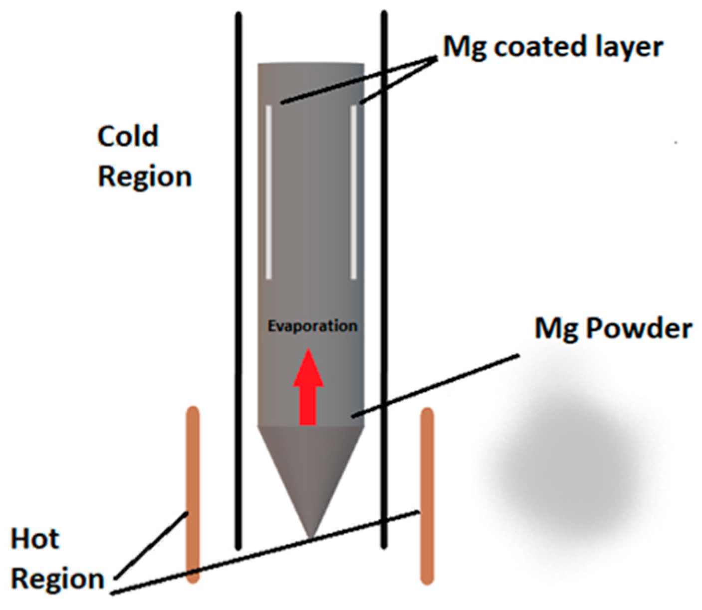
2. Materials and Methods

The MgB2 wires were made by using the powder-in-tube (PIT) and Mg coating methods [33]. In this study, the inner surface of an iron tube (outer/inner diameter: 12/9 mm) was coated with magnesium. A schematic representation of the Mg coating process is shown in Figure 1.
A small amount of Mg powder (PVZ, 99%, 325 mesh) was added to an iron tube (lit = 250 mm). The tube was placed inside a long steel tube (lst = 1800 mm) with a valve to heat the tube in a vertical furnace. The temperature of the furnace was increased to 600 °C under vacuum at a rate of 5 °C/min, and then the steel tube was kept at 600 °C for 15 min to complete the Mg coating process [33]. The stoichiometric Mg + 2B powder was ball milled and mixed for 3 h using a Retsch PM 100 (Retsch GmbH, Haan, Germany) planetary ball mill (rotation speed 200 rpm, ball to powder ratio 4), and then the mixture was filled into an internally Mg-coated iron tube using the PIT method. The boron powder mixture consisted of two distinct types of powders differing in terms of purity and particle size: semicrystalline boron (PVZ-B, 95–97% purity, and particle sizes <1 µm) and amorphous nanoboron (PVZ-B, 98.5% purity, and particle sizes <250 nm). These powders were used in equal masses [26]. The Fe/MgB2 wire was produced with a 0.81 mm diameter by using a cold drawing process (filling factor of superconducting material—40%).
The tubes prepared in this way were annealed at a temperature of 700 °C for 40 min under varying argon pressures of 0.1 MPa and 1.1 GPa (Table 1).
Following heat treatment, the wires were cut into short pieces, which were subsequently polished to examine the structural morphology in both longitudinal and cross sections. Analyses of the microstructure and composition were performed by using scanning electron microscopy SEM; FEI Nova Nano SEM 230 (Hillsboro, OR, USA) and a Quanta 3D FEG (Quanta, Hillsboro, OR, USA).
Additionally, cross-sections were taken by using an optical microscope (Olympus GX41, Olympus Corporation, Tokyo, Japan). The porosity (density-color map) analysis of the samples was carried out by using software (Kameram CMOS, version 2.11.5.6). The colors were assigned based on the intensity of the reflected light, with denser structures reflecting significantly more light than weaker structures.
Transport measurements of critical parameters were made by using the Physical Property Measurement System (PPMS) for 100 mA and 19 Hz in a perpendicular magnetic field. The critical parameters were determined based on the criteria of 10% for Birr, 50% for Tc, and 90% for Bc2.

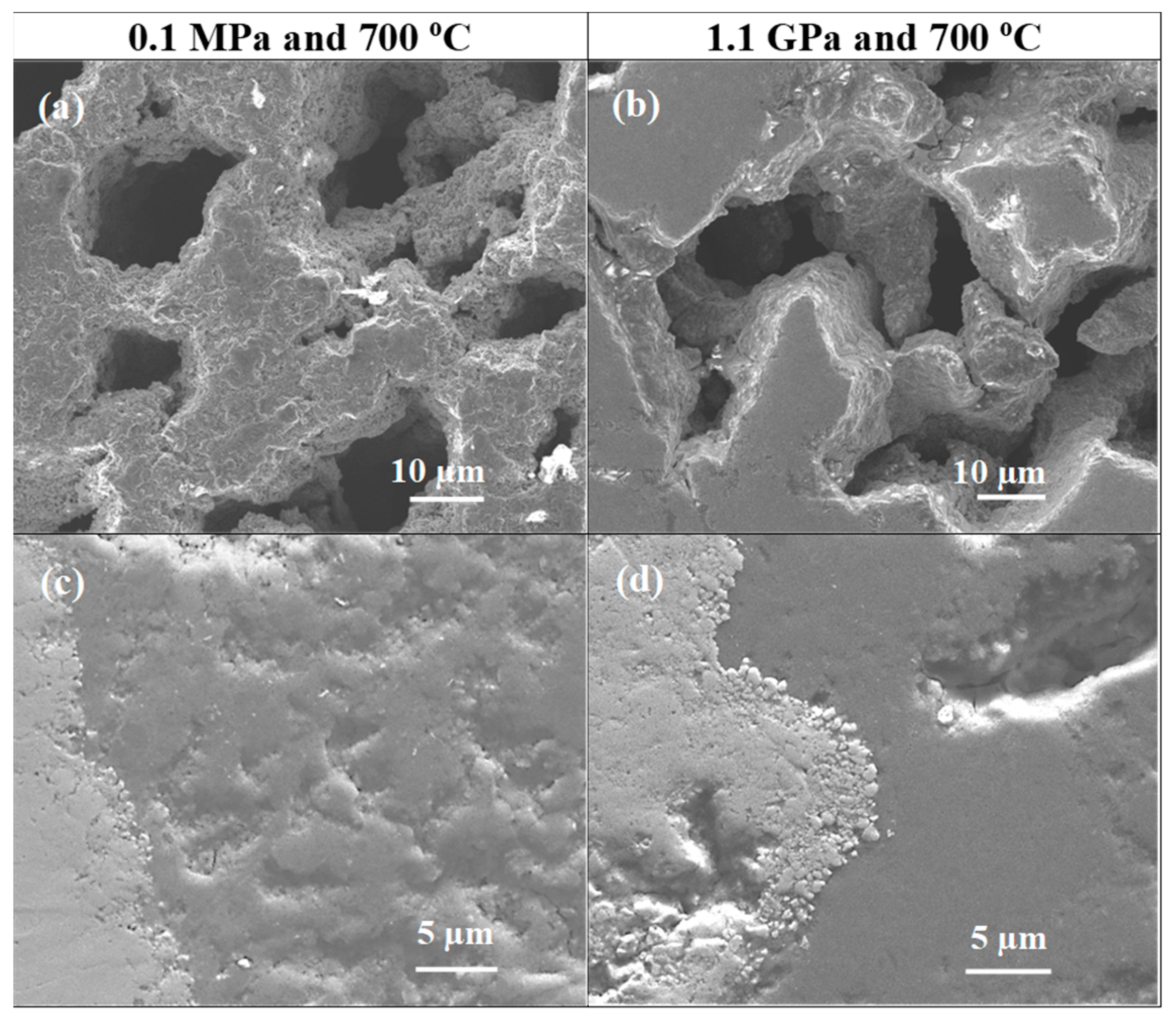
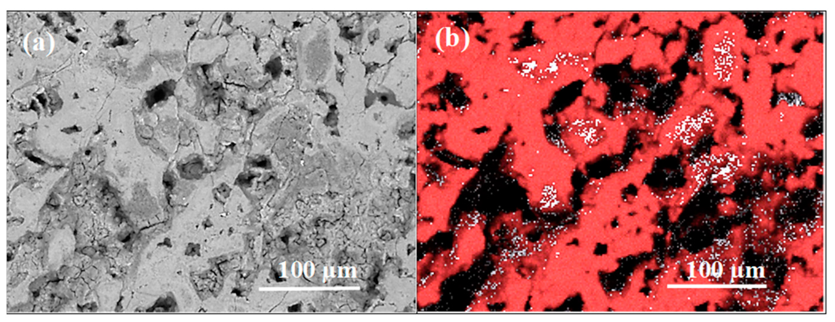
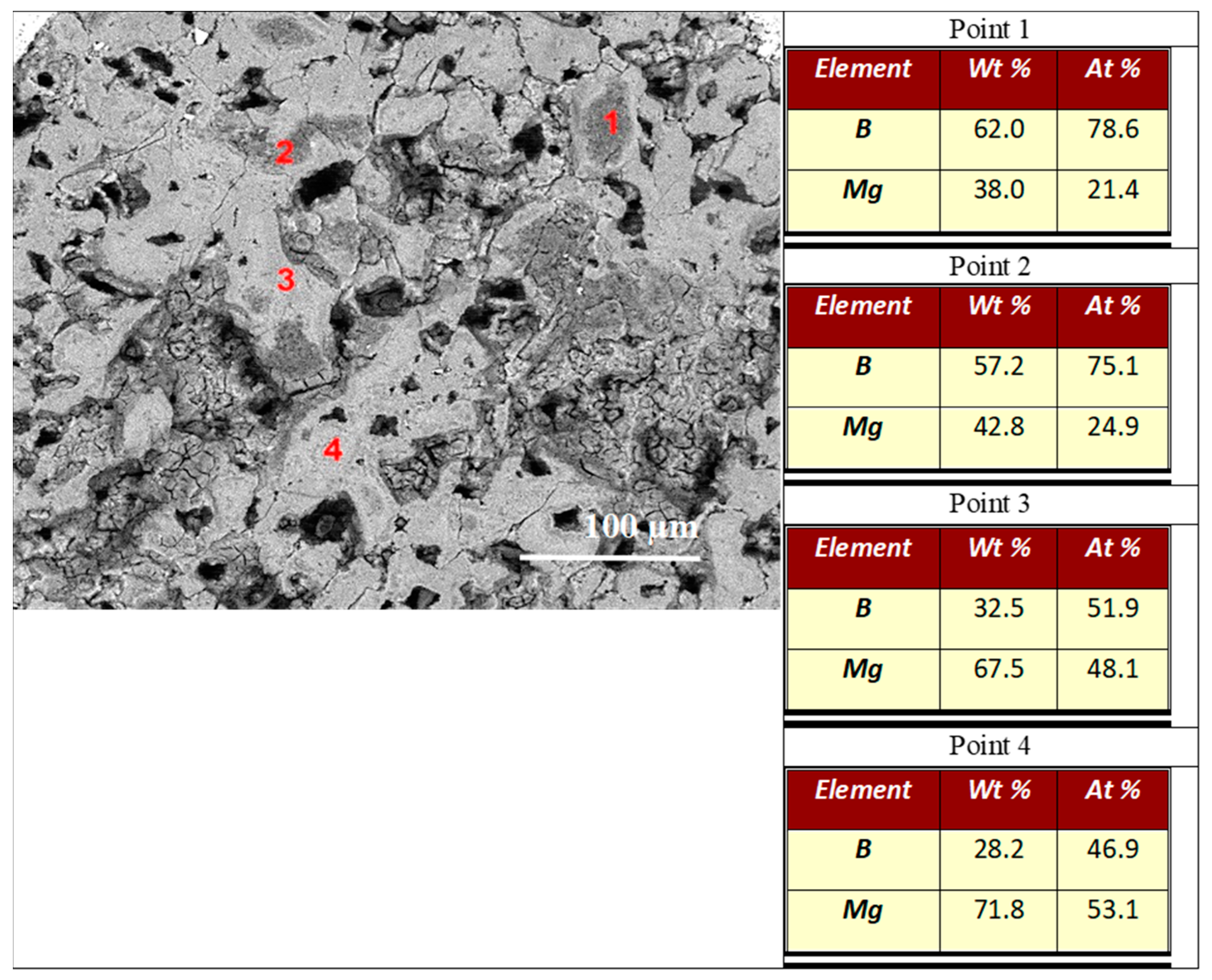
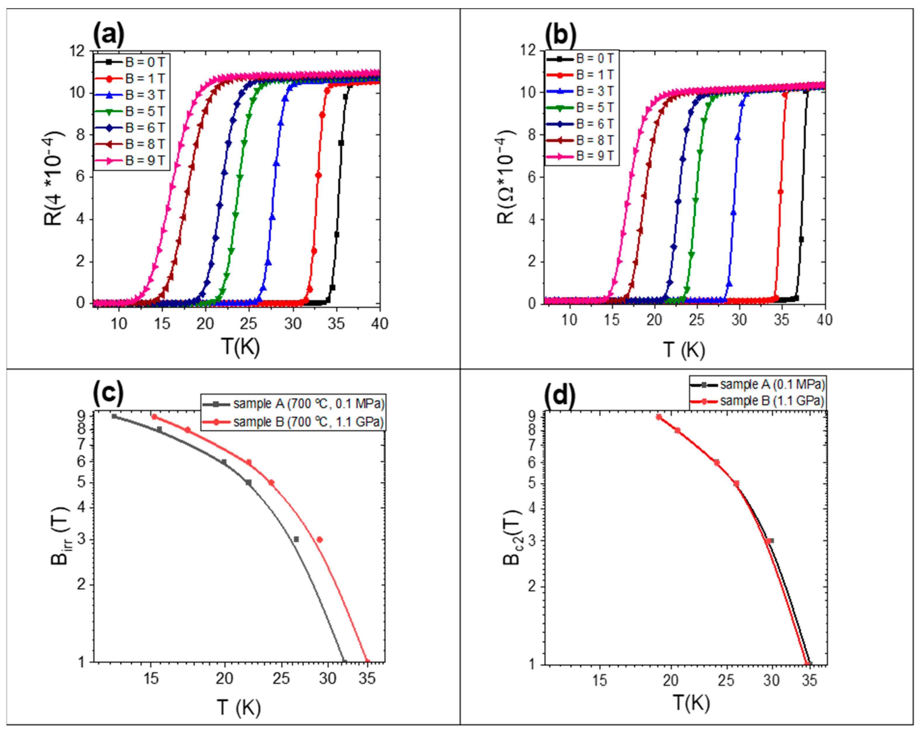
3. Results and Discussion

In this paper, for the first time, the impact of thermal treatment under high isostatic pressure on the morphology and critical parameters of PIT MgB2 wires made by using the Mg coating process is presented. We demonstrate that the Mg coating process significantly reduced the formation of intermetallic phases between the superconducting MgB2 material and the iron shield, e.g., iron borides. These phases were also observed in Fe-sheathed MgB2 wires [27]. These phases are unfavorable because they reduce the amount of the superconducting phase, lengthen the path of current penetration into the superconducting material, and change the mechanical properties of the PIT MgB2 wires in a negative manner. Additionally, our results indicate that the Mg coating process may replace diffusion barriers (e.g., Nb and ex situ MgB2) in the future [34,35]. This approach will reduce the price of PIT MgB2 wires and simplify their production. Moreover, Mg coating will allow for homogeneous structures of MgB2 material to be obtained in wires longer than 1 km, which is necessary for superconducting coils [1,3].

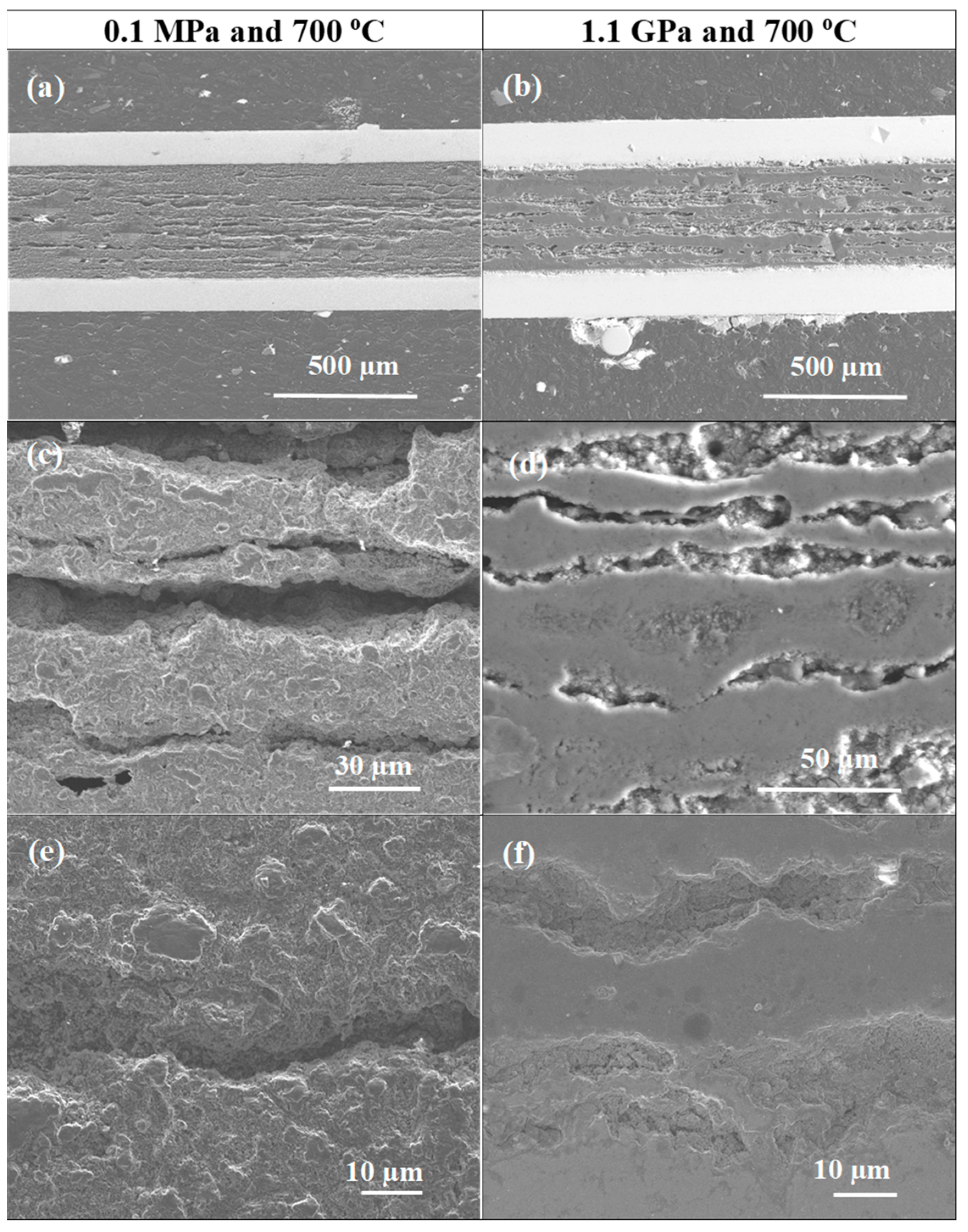
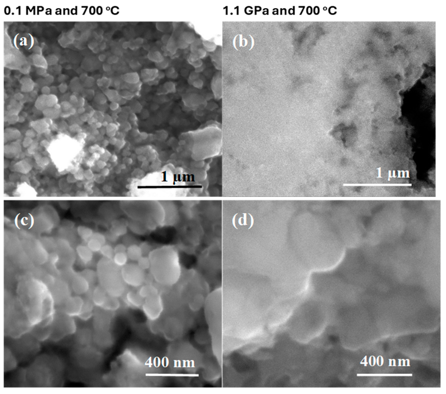
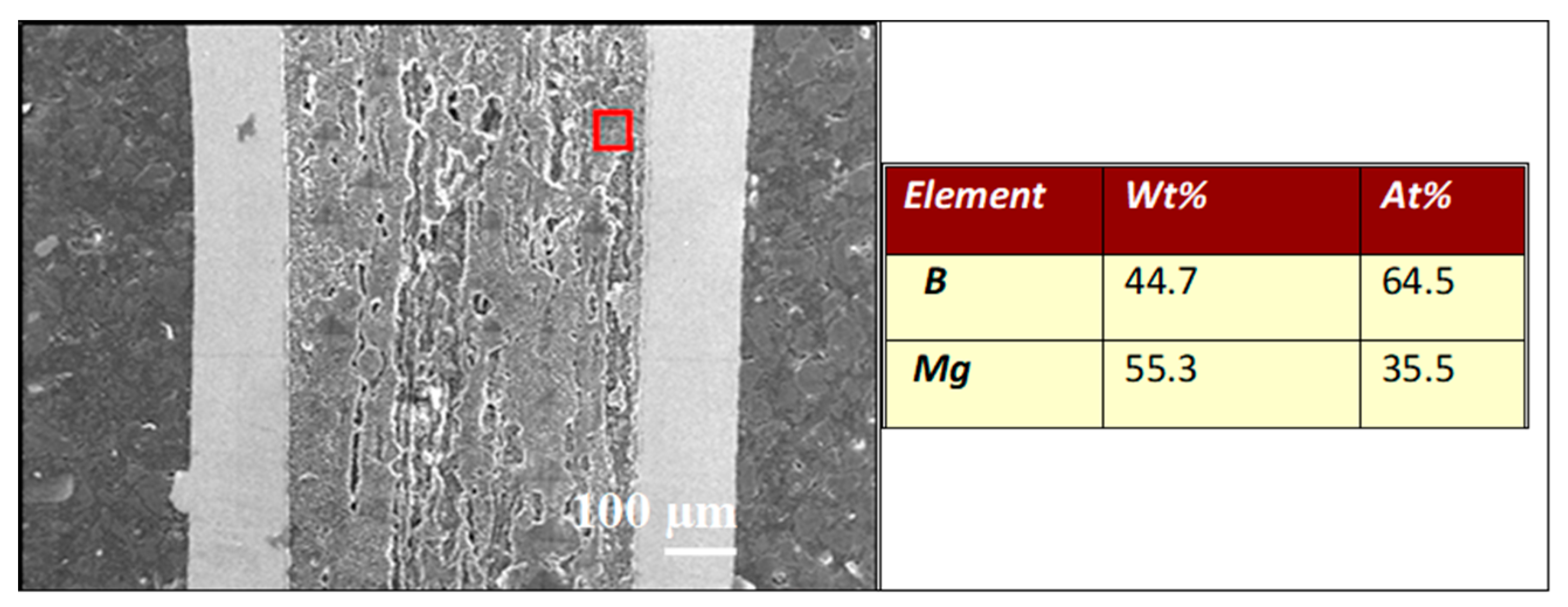
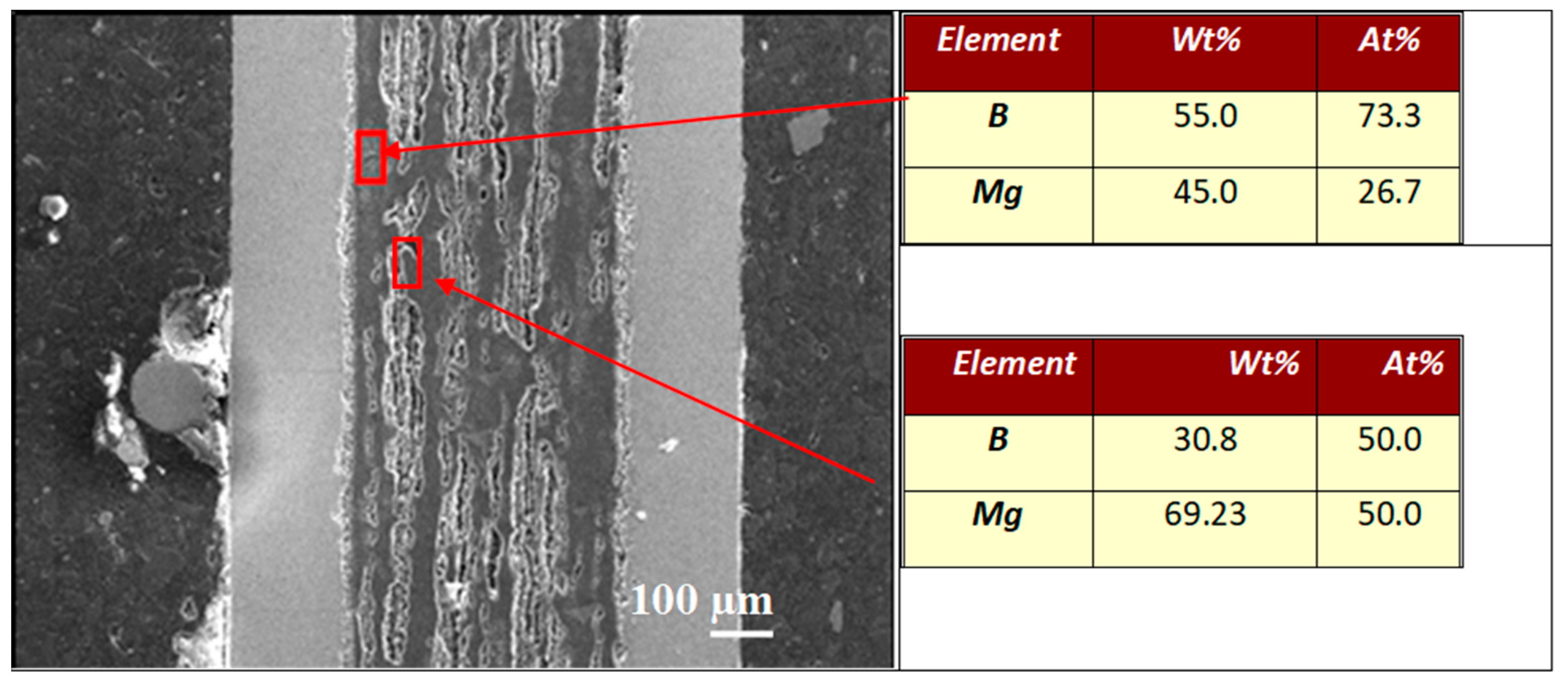
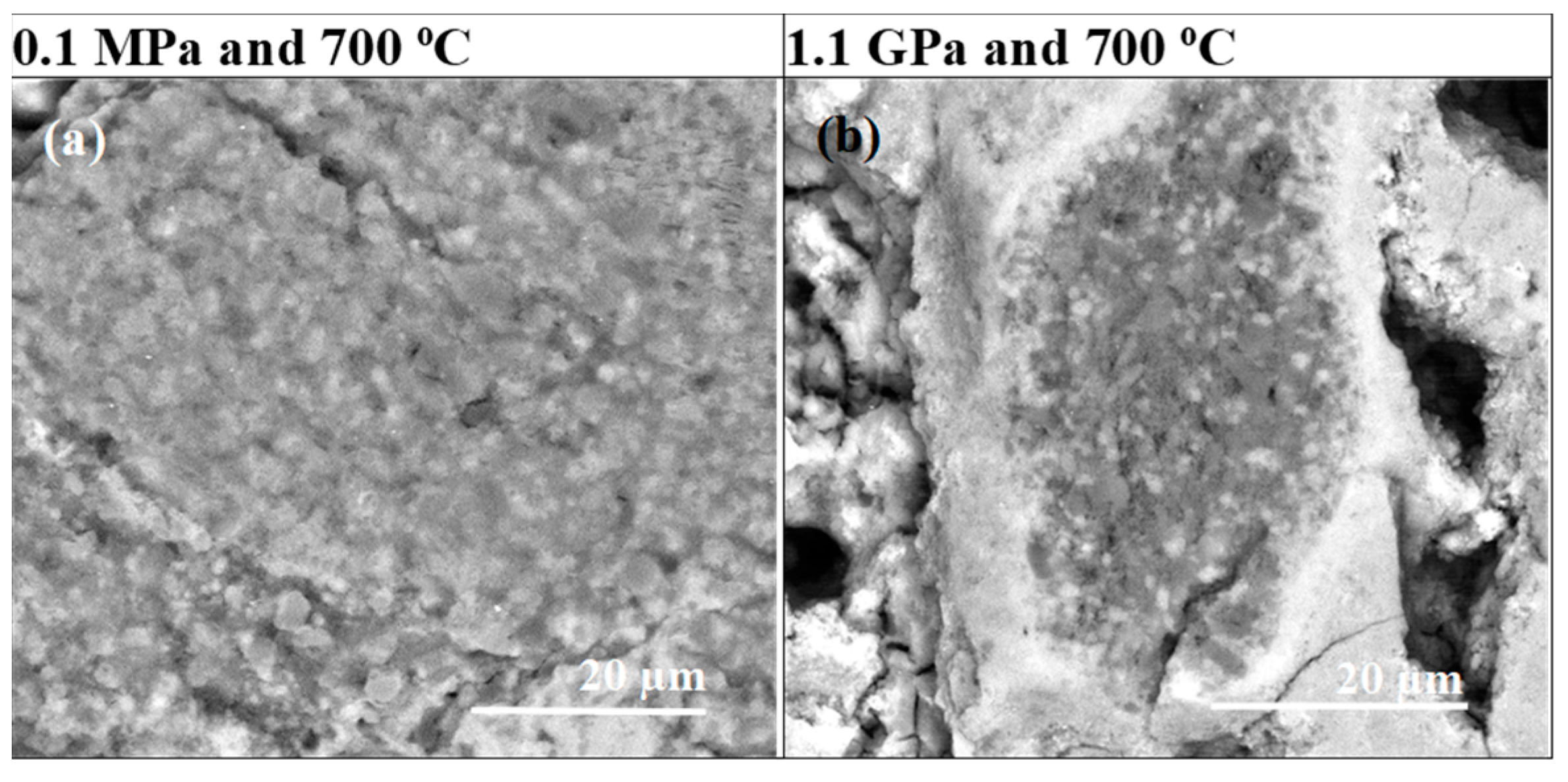
3.1. Structural Analysis of MgB2 Wires

Figure 2 and Figure 3 show the morphologies of samples A and B, which were heated and treated under low and high isostatic pressures. The longitudinal section results show that samples heat treated under low and high isostatic pressures have different layered structures.
Sample A (0.1 MPa) has a layered structure composed of small grains, high porosity, short connections between grains, and low density. However, sample B was (Figure 2) heat treated under high isostatic pressure and has a layered structure consisting of two regions. One has a high density, and the other has a low density (Figure 2d). Moreover, in Figure 2a–d, we see large voids that were created as a result of the diffusion of Mg into layer B. This indicated that the superconducting phase MgB2 was formed. Jung et al. [36] have indicated that Mg + 2B material could shrink by 25% during the formation of the superconducting MgB2 phase.
The pictures taken at high magnification in Figure 3 show that sample A has a grain size of up to 200 nm and a void size of up to 400 nm. However, sample B has a uniform and homogeneous structure without any voids (Figure 3b,d).
The analyses given in Figure 4 indicate that the low-density region in sample B is formed by unreacted B, with a grain size of up to 250 nm.
The backscattered electron (BSE) analysis showed that sample A had a uniform MgB2 phase distribution and did not contain unreacted Mg or B (Figure 5a,c).
Furthermore, the BSE results (Figure 4b,d) show that sample B has a large amount of unreacted B and Mg. Figure 4 shows that unreacted B can appear in both layered and island structures. This result is very important because it reveals the morphology and distribution of the layers of unreacted B. Susner et al. [29] have shown that Mg diffused into the B layer and created a superconducting MgB2 phase and voids. Based on these results, it can be concluded that the unreacted B layers have the greatest influence on the shape, thickness, and distribution of the layered structure. This also indicates that interruptions in the layered structure and weak connections between layered structures result from the nonuniform distribution of B before the synthesis reaction. Our results indicate that further research should be devoted to obtaining a more uniform distribution of B layers and increasing the density of the unreacted B layer in PIT MgB2 wires. This approach ensures a more uniform layer structure, a greater number of connections between layers, and a higher critical current density.
The results in Figure 6a show that sample A has uniformly distributed B and Mg. This indicates that the superconducting MgB2 phase has a uniform structure in sample A. However, the results in Figure 6b–d show that sample B has regions with high B contents that are distributed nonuniformly in the wire. This also reveals a nonuniform distribution of the superconducting MgB2 phase and pure (unreacted) Mg.
The EDS analysis in Figure 7 shows that sample A has a homogeneous distribution of Mg (35.5 at %) and B (64.5 at %), facilitating the homogenous formation of the MgB2 phase. The results in Figure 8 show that sample B has regions with excess B (73 at %—B, 27 at %—Mg) and others with equal amounts of Mg and B (50 at %—Mg and B). Sample B has three different regions: pure (unreacted) Mg, pure (unreacted) B, and the superconducting MgB2 phase.
The results obtained from the longitudinal section indicate that the layered structure of sample A, created under low isostatic pressure and in the liquid state of Mg, consists mainly of high-porosity MgB2. The results obtained for sample B show that the layered structure consists of three regions: pure Mg, pure B, and the superconducting MgB2 phase. The pure Mg and the superconducting MgB2 phase form high-density regions. However, low-density regions are formed due to the presence of pure B. Since an isostatic pressure of 1.1 GPa increases the melting point of Mg to 730 °C, Mg is in the solid state; therefore, unreacted Mg and B remain in the structure [6,37]. The process of Mg diffusion into the B layers slows down when Mg is in the solid-state phase. The second reason may be the use of crystalline boron with a grain size of 1 μm in sample A. Kim et al. [25] have indicated that crystalline boron with large grains reacted more slowly than nano amorphous boron (especially during reactions in the solid Mg state). Another factor influencing Mg diffusion is the density of the B layer. Li et al. have shown that the high density of the B layer significantly slowed the Mg diffusion process [38]. The results presented in [27] show that the solid-state Mg synthesis reaction at low isostatic pressure (630 °C, 0.1 MPa, 40 min) does not create any voids; large Mg particles and pure B remain. This indicates that the diffusion of Mg in the solid-state in the PIT MgB2 wires is very slow. On the other hand, based on our results, heat treatment under high isostatic pressure in the solid-state significantly accelerates the process of Mg diffusion into the B layers in PIT MgB2 wires. This is due to the large number of voids formed in sample B as a result of the diffusion of Mg to the B layer and the formation of the superconducting MgB2 phase. This also indicates that the synthesis reaction and Mg diffusion during the HIP process are more dependent on the pressure than the annealing temperature during the reaction in the solid-state phase of Mg.
The cross-sectional images in Figure 9 show that sample A has a different morphology than sample B. Sample A has a granular structure with large and small voids. However, sample B has large voids and dense surfaces without voids.
The backscattered electron (BSE) analysis of the cross section shows that sample A had a homogeneous material distribution and no pure B (Figure 10a). However, the BSE (Figure 10) and EDS (Figure 11) results show that sample B has a large amount of unreacted B. The EDS analysis of sample A shows that it has a homogeneous composition. However, sample B has two regions, one with an excess of B and one with an equal amount of Mg and B. The results for sample B in Figure 10b, Figure 11 and Figure 12 show that the regions with excess B have different shapes and surfaces. These results are very important because a layered structure consists of layers with different shapes (e.g., thickness and width). The cross-sectional examination revealed that sample A was a homogeneous superconducting material with a granular structure and a large number of pores (voids). However, the cross-section of sample B consists of three phases: the MgB2 superconducting phase, pure (unreacted) B, and pure (unreacted) Mg. The high-density regions have a large amount of Mg. However, the low-density regions are mainly composed of B. The apparent feature results shown in Figure 2 and Figure 12 reveal that samples A and B have similar longitudinal and cross-sectional compositions and morphologies. This indicates high uniformity in terms of the morphology of samples A and B.
The images in Figure 13a,c were taken using an optical microscope. Sample B has a large number of small regions of high density; in contrast, sample A has large voids and large regions of low density. The EDS analysis shows that these regions were composed largely of pure Mg (Figure 5a, Figure 6, Figure 7, Figure 10a and Figure 12). Moreover, the results in Figure 13a show that sample A has a very uniform structure (similar porosity) of superconducting MgB2 material in the layers. Figure 13b,d shows the color maps for the porosity of the samples. The colors were defined according to the intensity of the reflected light. The dense structure exhibited a significantly greater light reflection (navy blue, pink and brown) than the weak structure (green, red) did. The EDS analyses of the cross-section and longitudinal section revealed that sample A mainly has the superconducting MgB2 phase without pure Mg or B. The navy blue and red colors in Figure 13b represent the MgB2 superconducting phase. The color mapping allows for the porosity analysis (density) of the layered structure and the connections between the layered structures. Figure 13b shows that the layered structure in sample A consists of dense regions (lower porosity) inside and low-density regions outside (higher porosity). Furthermore, the connections between the layers result in a significantly high porosity (low density). This indicates that there are fewer connections between individual superconducting MgB2 layers. The lack of proper connections at the junctions between superconducting layers reduces the transport critical current density in PIT MgB2 wires. These results indicate that the porosity of the interlayer connections should be reduced to achieve a higher transport critical current density in PIT MgB2 wires. These results show, for the first time, the importance of the morphology of the regions connecting the layered structures with each other for higher critical currents.
The results in Figure 13d show that sample B has a very heterogeneous morphology (low- and high-porosity regions). Figure 13d shows that sample B has a small number of navy blue regions and a large number of red regions. Dark blue regions are formed at the outer parts of dense regions (excess Mg–Figure 12). Based on the results given in Figure 4, Figure 5b, Figure 6b,c, Figure 8, Figure 10b, Figure 11 and Figure 12, it can be concluded that the HIP process allows us to obtain superconducting MgB2 material (in the dark blue regions) with a high density on the outer surface with excess Mg. This may suggest that the high isostatic pressure applied during the solid-state Mg synthesis reaction influences the formation and porosity of the MgB2 material, but the heating temperature does not.

3.2. Irreversible Magnetic Field Analysis for MgB2 Wires

The results presented in Figure 14a,b show that after the HIP process the sample has a lower resistance in the normal state by 6% than the sample heated under low isostatic pressure. This suggests that the HIP process creates more connections. Moreover, the R–T curves after the HIP process have a sharper transition to the resistive state than the R–T curves after heating under low isostatic pressure. This indicates that the MgB2 superconducting phase is more homogeneous after the HIP process.
Transport measurements indicated that both samples have similar critical temperatures of approximately 36 K. Sample B has a higher Birr than sample A in the temperature range from 10 K to 35 K (Figure 14a). Previous research [39] has suggested that Birr values depend on the pinning centers. Our study supports this, as we observed an increase in pinning center density after the HIP process, leading to improved Birr performance due to the increased density of pinning centers. It was observed that Bc2 is similar for the samples heated at low and high isostatic pressures (Figure 14b). Bc2 is dependent on the mean free path and superconducting coherence length [40]; therefore, the HIP process does not affect these parameters.

4. Conclusions

Our study showed that the Mg coating method can significantly reduce the reactions of B with the Fe sheath. The shape, uniformity, and continuity of the layered structure (cracks, gaps) depend on the homogeneity of the B layer before the synthesis reaction. Additionally, studies show that the formation of a layered structure depends on the annealing temperature (in the liquid or solid-state), isostatic pressure, type of boron, and density of layer B before the synthesis reaction. On the basis of tests performed by using an optical microscope and software (Kameram CMOS), we observe that the inner parts of the layered structure possess minimal porosity, while greater porosity is present externally. Moreover, these tests indicate that high porosity occurred at the interlayer connection region and was accompanied by a small number of intergrain connections. Moreover, studies have shown that the layered structure of a sample heat treated under low isostatic pressure has large voids, a heterogeneous layered structure, and high porosity. However, the layered structure of the sample heat treated under high isostatic pressure has superconducting MgB2 material, pure B, pure Mg, and high-density layers with excess Mg. Additionally, the HIP process leads to the formation of high-field pinning centers in PIT MgB2 wires made using the Mg coating technique.

Author Contributions

Conceptualization, D.G.; methodology, D.G. and H.Y.; formal analysis, D.G., A.Z., I.B. and T.C.; investigation, D.G., M.B., A.Z., D.A., F.K. and H.Y.; resources, M.B., D.A., F.K., H.Y., I.B. and T.C.; writing—original draft preparation, D.G.; writing—review and editing, D.G.; visualization, T.C.; funding acquisition, T.C. All authors have read and agreed to the published version of the manuscript.

Funding

This research was funded by the statutory sources of the Institute of Low Temperature and Structure Research, PAS, and the Department of Materials Technology, Military University of Technology (Grant No. UGB-22-727).

Institutional Review Board Statement

Not applicable.

Informed Consent Statement

Not applicable.

Data Availability Statement

Data are contained within the article.

Acknowledgments

Andrzej Morawski heat treated the samples under high isostatic pressure at the Institute of High Pressure Physics PAS, Sokolowska 29/37, 01-142 Warsaw, Poland.

Conflicts of Interest

The authors declare no conflicts of interest.

References

  1. Yagaia, T.; Mizunoa, S.; Okuboa, T.; Mizuochia, S.; Kamibayashia, M.; Jimboa, M.; Takaoa, T.; Hiranob, N.; Makidac, Y.; Shintomic, T.; et al. Development of design for large scale conductors and coils using MgB2 for superconducting magnetic energy storage device. Cryogenics 2018, 96, 75–82. [Google Scholar] [CrossRef]
  2. Ballarino, A.; Flükiger, R. Status of MgB2 wire and cable applications in Europe. J. Phys. Conf. Ser. 2017, 871, 012098–0120105. [Google Scholar] [CrossRef]
  3. Parizh, M.; Lvovsky, Y.; Sumption, M. Conductors for commercial MRI magnets beyond NbTi: Requirements and challenges. Supercond. Sci. Technol. 2017, 30, 014007. [Google Scholar] [CrossRef] [PubMed]
  4. Buzea, C.; Yamashita, T. Review of superconducting properties of MgB2. Supercond. Sci. Technol. 2001, 14, R115–R146. [Google Scholar] [CrossRef]
  5. Huang, X.; Mickelson, W.; Regan, B.C.; Zettl, A. Enhancement of the upper critical field of MgB2 by carbon-doping. Solid State Commun. 2005, 136, 278–282. [Google Scholar] [CrossRef]
  6. Avedesian, M.M.; Baker, H. Magnesium and Magnesium Alloys; ASM International: Materials Park, OH, USA, 1999; pp. 7–11. [Google Scholar]
  7. Muralidhar, M.; Shadab, M.; Sai Srikanth, A.; Jirsa, M.; Noudem, J. Review on high-performance bulk MgB2 superconductors. J. Phys. D Appl. Phys. 2024, 57, 053001. [Google Scholar] [CrossRef]
  8. Flükiger, R.; Suo, H.L.; Musolino, N.; Beneduce, C.; Toulemonde, P.; Lezza, P. Superconducting properties of MgB2 tapes and wires. Phys. C Supercond. 2003, 385, 286–305. [Google Scholar] [CrossRef]
  9. Mackinnon, I.; Shabazi, M.; Alarco, J.; Talbot, P.C. Low temperature decomposition of metal borohydride drives autogenous synthesis of MgB2. Supercond. Sci. Technol. 2017, 30, 055004. [Google Scholar] [CrossRef]
  10. Rogalla, H.; Kes, P.H. 100 Years of Superconductivity; Chapman and Hall: London, UK, 2011; pp. 713–826. [Google Scholar]
  11. Zhang, P.; Zhang, Y.; Li, C.; Zhang, Y.; Shen, S.; Ruan, G.; Zhang, J.; Noudem, J.G. The influence of preparation temperature on the different facets of bulk MgB2 superconductors. Micromachines 2023, 14, 988. [Google Scholar] [CrossRef]
  12. Gao, Z.; Grovenor, C.R.; Speller, S.C. Correlation between microstructure and superconducting properties of MgB2 bulk samples with Mg addition and Mg/hBN co-additions. Supercond. Sci. Technol. 2023, 36, 094001. [Google Scholar] [CrossRef]
  13. Dadiel, J.L.; Sugiyama, J.; Sakai, N.; Takemura, K.; Oka, T.; Ogino, H.; Muralidhar, M.; Murakami, M. Improved connectivity of MgB2 bulk superconductor via in situ-ex situ co-synthesis. J. Supercond. Nov. Magn. 2023, 36, 1097–1102. [Google Scholar] [CrossRef]
  14. Matthews, G.A.B.; Mousavi, T.; Santra, S.; Grovenor, C.R.M.; Grant, P.S.; Speller, S. Improving the connectivity of MgB2 bulk superconductors by a novel liquid phase sintering process. Supercond. Sci. Technol. 2022, 35, 065005. [Google Scholar] [CrossRef]
  15. Shahabuddin, M.; Madhar, N.A.; Alzayed, N.S.; Asif, M. Uniform dispersion and exfoliation of multi-walled carbon nanotubes in CNT-MgB2 superconductor composites using surfactants. Materials 2019, 12, 3044. [Google Scholar] [CrossRef]
  16. Yeoh, W.K.; Cui, X.Y.; Gault, B.; De Silva, K.S.B.; Xu, X.; Liu, H.W.; Yen, H.-W.; Wong, D.; Bao, P.; Larson, D.J.; et al. On the roles of graphene oxide doping for enhanced supercurrent in MgB2 based superconductors. Nanoscale 2014, 6, 6166. [Google Scholar] [CrossRef]
  17. Xiang, F.X.; Wang, X.L.; Xun, X.; De Silva, K.S.; Wang, Y.X.; Dou, S.X. Evidence for transformation from δTc to δl pinning in MgB2 by graphene oxide doping with improved low and high field Jc and pinning potential. Appl. Phys. Lett. 2013, 102, 152601–152606. [Google Scholar] [CrossRef]
  18. Da Silva, L.B.S.; Serquis, A.; Hellstrom, E.E.; Rodrigues, D., Jr. The effect of AlB2 addition on MgB2 superconducting bulks. Supercond. Sci. Technol. 2023, 36, 045013. [Google Scholar] [CrossRef]
  19. Erdem, Ö. Comparison of superconducting properties of bulk MgB2 samples with pyrene additive produced by B powder and C encapsulated B powder. J. Low Temp. Phys. 2024, 214, 53–67. [Google Scholar] [CrossRef]
  20. Zhao, Q.; Chen, Y.; Qin, B.; Hu, C.; Xia, G.; Hao, L.; Ping, X. Synthesis of three-dimensional carbon nanosheets and its flux pinning mechanisms in C-doped MgB2 superconductors. Materials 2022, 15, 7530. [Google Scholar] [CrossRef] [PubMed]
  21. Hendrik, H.; Herbirowo, S.; Aryanto, D.; Nugraha, H.; Darsono, N.; Utomo, E.P.; Pramono, A.W.; Imaduddin, A. The effect of Ni doping in powder-in-tube-MgB2 material. AIP Conf. Proc. 2021, 2382, 020002. [Google Scholar]
  22. Serquis, A.; Civale, L.; Hammon, D.L.; Liao, X.Z.; Coulter, J.Y.; Zhu, Y.T.; Jaime, M.; Peterson, D.E.; Mueller, F.M.; Nesterenko, V.F.; et al. Hot isostatic pressing of powder in tube MgB2 wires. Appl. Phys. Lett. 2003, 82, 2847. [Google Scholar] [CrossRef]
  23. Serquis, A.; Civale, L.; Coulter, J.Y.; Hammon, D.L.; Liao, X.Z.; Zhu, Y.T.; Peterson, D.E.; Mueller, F.M.; Nesterenko, V.F.; Indrakanti, S.S. Large field generation with a hot isostatically pressed powder-in-tube MgB2 coil at 25 K. Supercond. Sci. Technol. 2004, 17, L35–L37. [Google Scholar] [CrossRef]
  24. Wan, F.; Sumption, M.D.; Rindfeisch, M.A.; Colling, E.W. Pressure-induced property improvement of magnesium diboride wire. IOP Conf. Ser. Mater. Sci. Eng. 2017, 279, 012024–012031. [Google Scholar] [CrossRef]
  25. Kim, J.H.; Heo, Y.U.; Matsumoto, A.; Kumakura, H.; Rindfeisch, M.; Tomsic, M.; Dou, S.X. Comparative study of mono-and multi-filament MgB2 wires with different boron powders and malic acid addition. Supercond. Sci. Technol. 2010, 23, 075014. [Google Scholar] [CrossRef]
  26. Akdoğan, M.; Yetiş, H.; Gajda, D.; Karaboğa, F.; Ülgen, A.T.; Demirtürk, E.; Belenli, I. Effect of the initial filling density on the critical current of in-situ Fe/MgB2 wires. J. Alloys Compd. 2015, 649, 1007–1010. [Google Scholar] [CrossRef]
  27. Gajda, D.; Zaleski, A.J.; Morawski, A.; Czujko, T.; Avci, D.; Karaboga, F.; Akdogan, M.; Yetis, H.; Cetner, T.; Belenli, I. The significant influence of packing density of unreacted Mg+ 2B mixture and heat treatment conditions on some of critical parameters for MgB2/Fe wires. J. Alloys Compd. 2021, 889, 161665. [Google Scholar] [CrossRef]
  28. Uchiyama, D.; Mizuno, K.; Akao, T.; Maeda, M.; Kawakami, T.; Kobayashi, H.; Kubota, Y.; Yasohama, K. Fibrous structure and critical current density of MgB2 superconducting wire. Cryogenics 2007, 47, 282–286. [Google Scholar] [CrossRef]
  29. Susner, M.A.; Daniels, T.W.; Sumption, M.D.; Rindfleisch, M.A.; Thong, C.J.; Collings, E.W. Drawing induced texture and the evolution of superconductive properties with heat treatment time in powder-in-tube in situ processed MgB2 strands. Supercond. Sci. Technol. 2012, 25, 065002. [Google Scholar] [CrossRef]
  30. Mroczek, Z.; Morawski, A.; Czujko, T.; Karaboğa, F.; Akdoğan, M.; Zaleski, A.J.; Małecka, M.; Cetner, T.; Yetiş, H.; Gajda, D.; et al. Influence of the lamella structure and high isostatic pressure on the critical current density in in situ MgB2 wires without a barrier. J. Alloys Compd. 2019, 776, 636–645. [Google Scholar] [CrossRef]
  31. Gajda, D.; Zaleski, A.J.; Morawski, A.J.; Babij, M.; Szymański, D.; Gajda, G.; Rindfleisch, M.A.; Shahbazi, M.; Hossain, M.S.A. Superior engineering critical current density obtained via hot isostatic pressing of MgB2 wires manufactured using nano-amorphous isotopic boron. J. Alloys Compd. 2021, 871, 159579. [Google Scholar] [CrossRef]
  32. Takahashi, K.; Kitaguchi, H.; Doi, T. The effect of MgB2 layer thickness on superconducting properties of MgB2/Ni multilayer thin films. Supercond. Sci. Technol. 2009, 22, 025008. [Google Scholar] [CrossRef]
  33. Karaboğa, F.; Avcı, D.; Yetiş, H.; Akdoğan, M.; Gajda, D.; Belenli, I. Improvement of in-situ Fe/MgB2 monofilamentary wires by internal Mg-coating process. J. Alloys Compd. 2017, 727, 20–26. [Google Scholar] [CrossRef]
  34. Tomsic, M.; Rindflesich, M.; Yue, J.; McFadden, K.; Phillip, J.; Sumption, M.D.; Bhatia, M.; Bohnenstiehl, S.; Collings, E.W. Overview of MgB2 Superconductor Applications. Int. J. Appl. Ceram. Technol. 2007, 4, 250–259. [Google Scholar] [CrossRef]
  35. Gajda, D.; Morawski, A.; Zaleski, A.; Yamamoto, A.; Cetner, T. A defect detection method for MgB2 superconducting and iron-based Ba (Fe, Co)2As2 wires. Appl. Phys. Lett. 2016, 108, 152601. [Google Scholar] [CrossRef]
  36. Jung, A.; Schlachter, S.I.; Runtsch, B.; Ringsdorf, B.; Fillinger, H.; Orschulko, H.; Drechsler, A.; Goldacker, W. Influence of Ni and Cu contamination on the superconducting properties of MgB2 filaments. Supercond. Sci. Technol. 2010, 23, 095006. [Google Scholar] [CrossRef]
  37. Pelissier, J.L. Determination of the phase diagram of magnesium: A model-potential approach in the sub-megabar range. Phys. Scr. 1986, 34, 838–842. [Google Scholar] [CrossRef]
  38. Li, G.Z.; Sumption, M.D.; Collings, E.W. Kinetic analysis of MgB2 layer formation in advanced internal magnesium infiltration (AIMI) processed MgB2 wires. Acta Mater. 2015, 96, 66–71. [Google Scholar] [CrossRef]
  39. Ghorbani, S.R.; Wang, X.L.; Hossain, M.S.A.; Dou, S.X.; Lee, S.-I. Coexistence of the δl and δTc flux pinning mechanisms in nano–Si–doped MgB2. Supercond. Sci. Technol. 2010, 23, 025019. [Google Scholar] [CrossRef]
  40. Kazakov, S.M.; Puzniak, R.; Rogacki, K.; Mironov, A.V.; Zhigadlo, N.D.; Jun, J.; Soltmann, C.; Batlogg, G.; Karpinski, J. Carbon substitution in MgB2 single crystals: Structural and superconducting properties. Phys. Rev. B 2005, 71, 024533. [Google Scholar] [CrossRef]
Figure 1. A schematic representation of the Mg coating process.
Materials 17 01362 g001
Figure 2. SEM images and longitudinal sections of single-core undoped MgB2 wires (a,c,e) sample heat treated under low isostatic pressure (0.1 MPa) and (b,d,f) sample annealed under high isostatic pressure (1.1 GPa).
Materials 17 01362 g002
Figure 3. High-magnification longitudinal sections of single-core undoped MgB2 wires (a,c) annealed under low isostatic pressure (0.1 MPa) and (b,d) annealed under high isostatic pressure (1.1 GPa).
Materials 17 01362 g003
Figure 4. Longitudinal section of single-core undoped MgB2 heated under high isostatic pressure (1.1 GPa): (ac) secondary electron (SE) and (d) energy-dispersive X-ray spectroscopy (EDS) analysis; red indicates Mg, and white indicates B.
Materials 17 01362 g004
Figure 5. Longitudinal section-backscattered electron (BSE) analysis of (a,c) sample A (0.1 MPa) and (b,d) sample B (1.1 GPa). Dark regions indicate B. Light regions indicate Mg.
Materials 17 01362 g005
Figure 6. Linear analysis of the sample composition for longitudinal sections of (a) sample A (0.1 MPa) and (bd) sample B (1.1 GPa). The red line denotes B, the green line shows Mg, and the blue line indicates the iron sheath (Fe).
Materials 17 01362 g006
Figure 7. EDS analysis of the longitudinal section of sample A (0.1 MPa).
Materials 17 01362 g007
Figure 8. EDS analysis of the longitudinal section of sample B (1.1 GPa). The red square indicates the place for the EDS analysis was performed.
Materials 17 01362 g008
Figure 9. The SEM photo cross-sections of single-core undoped MgB2 wires (a,c) annealed under low isostatic pressure (0.1 MPa), (b,d) annealed under high isostatic pressure (1.1 GPa).
Materials 17 01362 g009
Figure 10. The cross-sections of MgB2 wires-backscattered electron (BSE) analysis (a,b) sample A (0.1 MPa) and sample B (1.1 GPa). Dark regions indicate B. Light regions indicate Mg.
Materials 17 01362 g010
Figure 11. The cross-sections of sample B (1.1 GPa): (a) secondary electron (SE) and (b) energy dispersive X-ray spectroscopy (EDS) analysis. The red color indicates Mg, and the white color indicates B.
Materials 17 01362 g011
Figure 12. EDS analysis of cross-sections of sample B (1.1 GPa).
Materials 17 01362 g012
Figure 13. Morphological analysis via optical microscopy (a,b) cross-sections of sample A (0.1 MPa) and (c,d) cross-sections of sample B (1.1 GPa). The colors indicate the density of the MgB2 material. The low-density areas are yellow and green. Blue and pink indicate high density.
Materials 17 01362 g013
Figure 14. (a) Dependence of resistance on temperature for a sample heated under low isostatic pressure. (b) Dependence of resistance on temperature for a sample heated under high isostatic pressure. (c) Dependence of the irreversible magnetic field (Birr) on temperature. (d) Dependence of the upper magnetic field (Bc2) on temperature.
Materials 17 01362 g014
Table 1. Heat treatment processing parameters of undoped MgB2 wires.
Sample No.Pressure
[MPa]
Annealing Temperature
[°C]
Annealing Time
[min]
A0.170040
B110070040
Disclaimer/Publisher’s Note: The statements, opinions and data contained in all publications are solely those of the individual author(s) and contributor(s) and not of MDPI and/or the editor(s). MDPI and/or the editor(s) disclaim responsibility for any injury to people or property resulting from any ideas, methods, instructions or products referred to in the content.

