
Study on the High-Temperature Interaction between Coke and Iron Ores with Different Layer Thicknesses
1
Institute Research of Iron & Steel of Sha-Steel, Zhangjiagang 215625, China
2
School of Materials Science and Engineering, Chongqing University, Chongqing 400044, China
*
Author to whom correspondence should be addressed.
Materials 2024, 17(6), 1358; https://doi.org/10.3390/ma17061358
Submission received: 6 February 2024
/
Revised: 11 March 2024
/
Accepted: 14 March 2024
/
Published: 15 March 2024
(This article belongs to the Special Issue Metallurgical Process Simulation and Optimization—2nd Volume)
Abstract
:Coke plays a key role as the skeleton of the charge column in BF. The gas path formed by the coke layer in the BF has a decisive influence on gas permeability. At high temperatures, the interface between coke and ore undergoes a melting reaction of coke and a reduction reaction of ore. The better the reducibility of the ore, the more conducive it is to the coupling reaction of ore and coke. The melting loss reaction of coke becomes more intense, and the corresponding strength of coke will decrease, which will affect the permeability of the blast furnace and is not conducive to the smooth operation of the blast furnace. Especially with a deterioration in iron ore quality, BF operation faces severe challenges, which makes it necessary to find an effective way to strengthen BF operation. In this study, a melting-dropping furnace was used to develop and clarify the high-temperature interaction between coke and iron ores with different layer thicknesses. The influencing factors were studied by establishing a gas permeability mathematical model and observing the metallographic microscope images of samples after the coke solution loss reaction. The relationships between coke layer thickness, distribution of gas flow, and pressure drop were obtained. The results showed that, under certain conditions, the gas permeability property of a furnace burden has been improved after the coke layer thickness increased. Upon observing the size of coke particles at the interface reaction site, the degree of melting loss reaction can be determined. A smaller particle size indicates more melting loss reaction. A dripping eigenvalue for molten metal was introduced to evaluate the dynamic changes in the comprehensive dripping properties of molten metal of furnace burden, which showed that the dripping eigenvalue for the molten metal could deteriorate because of the unruly thickness and the coke layer thickness should be limited through considering the operational indicators of the blast furnace.
1. Introduction
Blast furnace technology is still the main ironmaking route, with a current global share of 70% [1]. Coke is the main material in blast furnaces, and it plays an important role in blast furnace operation. Coke functions not only as a reducing agent but also as a skeleton in the blast furnace [2]. The blast furnace is filled with furnace burden, molten slag, iron, and coke, which account for 1/3–1/2 of the furnace burden and determines the gas permeability [3,4].
The dissected blast furnace [5] showed that the coke solution loss reaction influenced the gas permeability of the upper part of BF [6,7,8], and there are many references available in this field [9,10]. In addition, the thickness of the coke layer is also an important factor affecting the distribution of gas flow. Unsuitable coke layer thickness may cause an unstable gas flow distribution as well as a central gas flow block, which threatens BF operation.
The coke layer thickness is a restrictive factor for normal BF production and raising the ratio of coal. It will affect the size of the coke window, the amount of CO produced, the permeability of the material layer, and the utilization rates of gas and heat energy. As the thickness of the coke layer increases, the degree of ore–coke mixing decreases, and the resistance generated by interface reactions decreases. At the same time, as the area of a single coke window increases, the stability and uniformity of gas permeability are improved, and the pressure is reduced. So, it is necessary to find the suitable coke layer thickness to optimize the BF index and its significant meanings and practical application value to ensure the stability of actual production.
In the past, most of the research on coke mainly focused on the type of coke, the ratio of mixed coke and the size of coke in the ore layer, and the influence of coke thickness on permeability is also discussed. However, due to the limitation of equipment, there are few literature studies about the influence of coke layer thickness on the drop performance of blast furnace burden. In fact, there were complicated interactions among the furnace burden, which could improve molten-metal dripping properties distinctly if effectively used [11,12]. Increasing the coke layer thickness could improve the permeability of BF, which resulted in an improvement in the dripping properties of molten metal. The Shougang Jingtang 2# blast furnace achieved long-term stable smelting of a large ore batch with a large coke ratio (thick coke layer) by using AB ore in the form of a small material volume [13]. However, the coke layer thickness cannot be increased indefinitely. Too thick a coke layer could generate huge resistance to the process of molten iron dripping, which is one of the important causes that lead to irregular furnace operation. The studies [14,15] show that an increase in the thickness of the coke layer means an increase in the thickness of the material layer, an increase in the “gas window” area of each layer of the soft melt zone, and an improvement in the permeability of the blast furnace. However, as the thickness of the blast furnace ore and coke layer increases, the pressure difference in the soft melt zone increases, and the total pressure difference slightly decreases to a certain point and then increases again.
In this paper, research on the interaction between coke and iron ores was based on the melting-drop furnace. The experiment of solution loss reaction of coke was carried out, and a mathematical model of gas permeability was established. To clarify the mechanism of the interaction, the dynamic changes in the influences of coke layers with different thicknesses on the permeability were investigated through the combination of experimental results and mathematical models, and then the influence of the thickness on the melt-dropping property of the burden was studied.
2. Materials and Experiment
2.1. Raw Iron Ores and Coke
The raw materials were iron ores and coke for field production, including sinter (S-1), pellets (P-1), and 2 lumps (O-1, O-2). The chemical compositions are listed in Table 1, and the quality of the coke is listed in Table 2. Quantitative analysis of the chemical composition of iron ore analyzed in accordance with GB/T 6730.87-2023 [16] Iron ores—determination of total iron and other multi-element content—wavelength dispersive X-ray fluorescence spectrometry (cobalt internal standard method), and the analysis of FeO is analyzed in accordance with GB/T 6730.8-2016 [17] determination of ferrous content in iron ores—potassium dichromate titration method. The composition analysis of coke shall be determined in accordance with GB/T 2001-2013 [18] coke industrial analysis method, M40 shall be determined in accordance with GB/T 2006-2008 [19] coke mechanical strength determination method, coke CSR shall be determined in accordance with GB/T 4000-2017 [20] coke reactivity and post reaction strength test method, and coke Ms shall be determined in accordance with ISO 728-2021 [21] size analysis by sieving. Because different chemical compositions of ores can lead to differences in the internal structure of minerals, affecting their reducibility, for eliminating the influence of different ore structures on the interfacial reaction between ore and coke, O-1 and O-2 with similar compositions but different origins, and different structures were selected to test the contrast.
In Table 2, M40 is the crushing strength of coke. CSR is coke strength after the reaction. Ms is the average particle size of coke. A is coke ash content. S is coke sulfur content. C is the fixed carbon content of coke.
2.2. Development of Melting-Drop Furnace
The working principle in a melting-drop furnace is shown in Figure 1. There are two parts of the equipment, which are the gas control part and the reacting part. The gas used in the experiment was mixed by the gas flow controller and injected from the side of the furnace body. After contacting the material layer, the gas passes through the material layer vertically. The pressure was measured by a pressure gauge, the temperature measured by a thermocouple, and the shrinkage rate of the sample bed was gathered by a control box for calculation and drawing curves. The sample bed, which consists of alternately packed ore and coke layers, was arranged in the reacting parts, as shown in Figure 2.
So, for each test, iron ore and coke with a layer thickness were placed in a graphite crucible (Figure 2), the inner diameter of which was 120 mm; there was a graphite gasket of the same size at the bottom on which samples could be placed; and 5-mm holes were evenly distributed on the graphite gasket, from which the drops will drop at high temperature. The maximum load of 0.35 MPa was applied to the sample bed from the top by the rod. The generated molten iron was collected in the sample mouth. The devices mentioned above were cleverly designed so that the gas could only pass through the packed bed without leakage. Then, the research on the influence of coke layers with different thicknesses on the high-temperature interaction between coke and iron ore could be carried out on this set of equipment.
In the experiment, the particle size range of the sample, the temperature, and the gas composition shall be executed in accordance with the national standard GB/T 34211-2017 [22]. The diameters of coke and ore in this experiment are 10–12.5 mm. Because the particle size ranges of ore and coke are unified, it can effectively avoid the impact of original particle size segregation on experimental results. In addition, the amount of coke and ore samples is determined based on the size of the crucible in the equipment.
3. High-Temperature Interaction between Coke and Iron Ores
3.1. Experimental Conditions
The experimental conditions of material charging are shown in Table 3.
In each experimental condition, the total amount of iron ore and coke is kept at 500 g and 80 g, respectively. The thickness of iron ore and coke is 160 mm, and the thickness of the coke layer was changed to 20 mm, 30 mm, and 40 mm. Moreover, 80 g coke can guarantee the amount when the thickness of the coke layer changes from 20 mm to 40 mm.
Figure 3 shows the experimental conditions for the temperature and gas composition. In order to simulate the melting behavior of iron ore in BF, the burden was heated to 900 °C in an N2 atmosphere, then the heating rate was slowed, and the gas composition was changed to simulate the environments of both.
3.2. Experimental Results
3.2.1. Dripping Properties of Molten Metal
In this study, it was impossible to observe the packed bed behavior during the high-temperature part; therefore, to evaluate the interaction between the coke and iron ores, the measured parameters were quantified. T10 and T40 were the temperatures when the packed bed shrinkage was 10% and 40%, respectively. Ts was the temperature when the pressure increased steeply, and Pmax was the highest value of the pressure. The S value was the integral of the pressure drop value over the cohesive zone, which reflected the permeability of the cohesive zone. The equation of S value is shown as Equation (1).
The testing results of dripping properties are listed in Table 4, and in order to maintain the reproducibility of the experimental results, each group of experiments was repeated twice. As the results show, the properties of furnace burden have been distinctly changed due to the change in coke layer thickness, embodied in softening temperature, softening interval, melting temperature, pressure drop, and S value.
3.2.2. Pressure Drop in Layer Thickness Condition
Figure 4 reflects the relationship between the pressure drop and the temperature in different conditions of coke layer thickness. The value of Ts increased in different degrees when the coke layer thickness increased, and that of five kinds of furnace burden increased to 1295.9 °C, 1289 °C, and 1300 °C, respectively. Increasing coke layer thickness contributed to raising the melting temperature and meeting the demand for a higher melting temperature during BF operation.
In the soft melt droplet layer, as the thickness of the coke layer increases, the skeleton effect of the coke strengthens, the permeability of the soft melt droplet layer improves, and the maximum pressure drop decreases. At the same time, as the thickness of the coke layer increases, with an increase in the ore layer thickness, the homogeneity of the ore coke weakens relative to the soft melting zone, the interaction between the ore coke weakens, and the softening and dripping temperatures both increase [23].
In addition, the coke layer is too thin, and due to the viscosity of the molten metal, it is easy to cause a decrease in permeability after infiltration into the coke layer, leading to fluctuations in gas flow. So, increasing the thickness of the coke layer can improve air permeability.
In Case 2 and Case 3, the pressure drop decreased distinctly due to the change in the coke layer. Pmax decreased from 9322 Pa to 6558.7 Pa and 4970 Pa. Compared with Case 4 and Case 5, the pressure peak value decreased by 2206 Pa.
3.2.3. Shrinkage Rate in Layer Thickness Condition
The relationship between shrinkage rate and temperature in different conditions of layer thickness is shown in Figure 5. Under the same charging condition, with an increase in the thickness of the coke layer from 20 mm to 30 mm and 40 mm, T10 decreased obviously, while T40 did not change greatly. The initial softening temperatures decreased by about 22 °C and 28 °C, respectively.
3.2.4. Effect of Coke Solution Loss
Figure 6 presents the dissected graphite crucible in conditions of different thicknesses, and the metallography images of the observed section are shown in Figure 7.
As shown in Figure 7, at the cross-sectional area of the surface of the coke layer and pig iron, there were many coke particles embedded in the pig iron. These particle sizes were inhomogeneous, ranging from 30 μm to 300 μm. The amount of coke particles was larger when the coke layer thickness was 20 mm than when it was 30 mm or 40 mm. Moreover, the particle sizes were far smaller at 40 mm than at 20 mm and 30 mm. That may illustrate the mechanical strength of the coke layer, which was damaged seriously due to smaller thickness and the wrecked coke particles mixed with molten iron.
4. Discussion
4.1. Solution Loss Reaction of Coke
The solution loss reaction of coke was affected by changing the thickness of the coke layer, which could wreck the coke in the cohesive zone and dropping zone. Since the downward movement of the modified coke is not conducive to gas–liquid infiltration of the lower part of the blast furnace, the solution loss reaction might reduce the utilization of chemical and thermal energy of BF gas, which is expressed by Equation (2).
The reduction reaction of iron oxide is presented by Equation (3), where the iron oxide was expressed by FeOx to facilitate analysis.
Through Equations (2) and (3), Equation (4) is obtained, which presents the coupling reaction between the solution loss reaction of coke and the reduction reaction of iron oxide.
Equation (4) could be a cycle on the utilization of CO and CO2. It can be seen from the equation that increasing the thickness of the coke layer could promote the reaction and generate more CO, which facilitates the reduction reaction.
In addition, the reaction that Equation (4) presents has a great influence on the mechanical strength of the coke layer. The research has shown [24] that at 1100 °C the reaction mode of coke is mainly based on permeation reaction, and with an increase in melting loss rate, the damage to the internal structure of coke increases, leading to a sharp decrease in CSR; for every 1% increase in melt loss rate, CSR decreases by about 1.38%. However, when the temperature exceeds 1350 °C, the melting loss reaction mainly concentrates on the outer surface of the coke, causing less damage to its internal structure. As the melting loss rate increases, the CSR does not change much; for every 1% increase in melt loss rate, CSR decreases by about 0.63%. The skeleton function of the coke layer would be seriously wrecked due to the thinner coke layer thickness, which would result in the blockage of the gas flow path and the destruction of the permeability of BF. The thickening of the coke carbon layer reduces the number of interfaces between the ore and coke, the pressure loss of the gas through the mixed layer, especially the block zone, decreases, the interface effect between the material surface decreases, the ‘coke window’ is more stable, the upper air flow distribution of the blast furnace is more reasonable, and the gas flow is more uniform in the circumferential distribution of the throat, which is conducive to the stable and smooth operation of the blast furnace.
4.2. Coke Layer Function in Cohesive Zone
The cohesive zone is the transition part between the lumpish zone and the dropping zone. The weak permeability of the cohesive zone may block the upward movement of gas flow at the center and develop edge gas, resulting in better permeability of the periphery than at the center of the cohesive zone. The pressure drop of BF is the sum of the pressure drop of the lump charging zone, cohesive zone, and dripping zone, as expressed by Equation (5).
As Figure 8 shows, the coke layer formed dendritic coke windows in the BF interior, and the gas flow distribution secondly turned center distribution into edge distribution. The pressure drop in the cohesive zone is calculated by Equation (6).
The coke windows would be destroyed when the coke layer was too thick, and the immediate increase in ΔPcz and ΔPc would lead to the disorder of gas flow distribution. In addition, the mechanical strength of coke was wrecked due to the solution loss reaction of coke, which further deteriorated the permeability.
In addition, the desolvation reaction of coke destroys the mechanical strength of coke and further deteriorates the permeability. Increasing the thickness of the coke layer is conducive to protecting the thickness of the ‘coke window,’ narrowing the height of the soft melt zone, improving the permeability of the overall material column, and better playing the role of the coke skeleton.
4.3. Mathematical Model of Permeability
The critical factor determining the normal operation of BF is ΔP/H. In order to quantify the permeability of the furnace charge, the permeability of burden was calculated by the Ergun equation [25], which is shown by Equation (7), where dp, u, ε, ρ, μ, φ were defined as particle diameter, gas velocity, void fraction, density, viscosity, and the shape factor, respectively. Furthermore, the coke average diameter was 10 mm, the void fraction was 0.418, and the shape factor was 0.785, as is shown in the research of Yamada [26].
Most of the gas flow in the cohesive zone may occur as lateral flow due to the great resistance in the cohesive zone, which is because of the small porosity resulting from the molten iron. Therefore, the ΔP/H could be analyzed by Equation (8).
where K, ρ, ω, L, n, hc, and ε were defined as a constant coefficient, gas flow density, velocity of gas flow in an uncharged furnace, cohesive interval, amount of coke layers, coke layer thickness, and void fraction of coke, respectively.
In this paper, as reported by Yamada [19], the density of gas flow is considered as 1.25 kg·m3, and the velocity of gas flow is 1.02 m·s−1. Furthermore, the void fraction is 0.418. As is shown in Equation (8), all of the influencing factors in the equation are the greatest influence due to power exponents. After the quantification of influencing factors, the resistance on gas flow in the cohesive was calculated. It is shown that the thickness of the coke layer, as well as the amount of the coke layer, are the determining factors of ΔP/H.
To confirm this conclusion, the calculation results of Equation (7) and the measurement results are compared, and the contrast results are shown in Figure 9. It can be seen that the results of the calculation show good agreement with the measurement result, which indicated that a higher thickness of the coke layer is beneficial to improve the permeability of the cohesive zone. That is because an increase in the thickness of the coke layer could lead to the diversion of the gas flow and make coke play a better role as “shutters”.
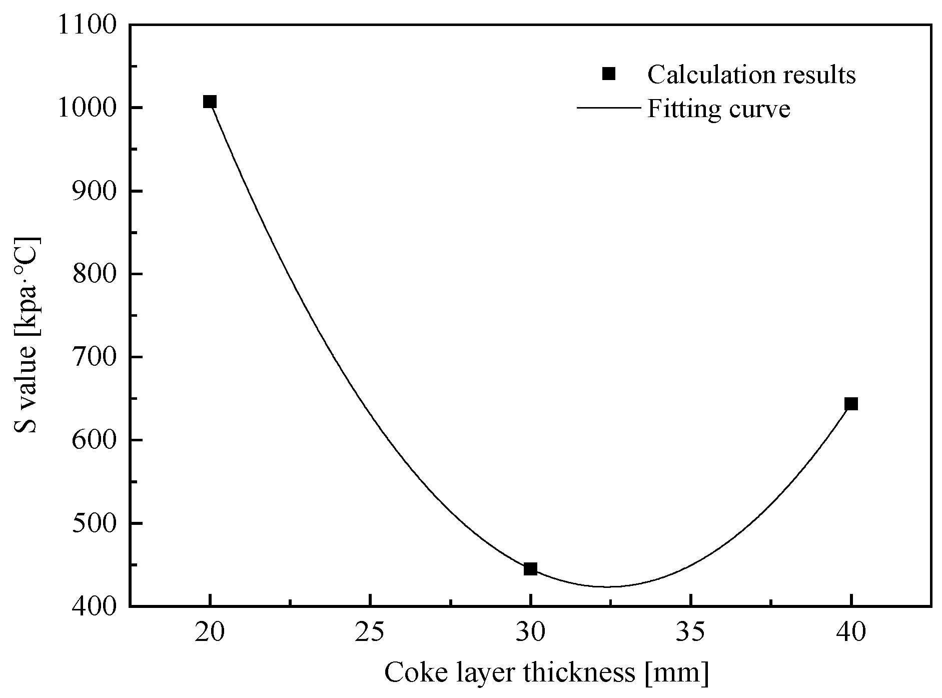
However, the BF is a synthesis reactor that is affected by temperature, pressure drop, BF burden, etc. It is not always possible to optimize the operation of a blast furnace by increasing the thickness of the coke layer. According to Table 4, the S value of the coke layer in thickness of 30 mm is the best of all the schemes, and it indicates that the coke layer thickness can not increase indefinitely. The relationship between the S value and the thickness of the coke layer was simulated using a mathematical model, and the fitting curve is listed in Figure 10.
It can be seen from Figure 10 that the relationship between the S value and the thickness of the coke layer is a quadratic function. When the layer thickness is higher than 30 mm, the influence of an increase in the coke layer thickness on the S value is completely opposite to that before. This is because the thickness of the coke layer increases too much so that the path inside the coke can be extended. In the dropping process of molten iron, the permeability of the coke layer decreases due to the excessive infiltration of molten iron. As a result, the permeability of the burden began to decline, which has a great resistance to the gas flow, thus hindering the dropping process of molten iron. Related studies have shown [27] that measures to improve the permeability of the soft melt zone can be taken by expanding the ore and coke batches to increase the thickness of the coke layer inside the soft melt zone, improve reducibility, and suppress interaction to reduce the radial width of the soft melt zone while improving the permeability of the soft melt layer. Therefore, expanding the thickness of the coke layer must have a ‘degree.’ When increasing the thickness of the coke layer, effective measures should be taken to open the center to prevent the deterioration of the permeability of the material column.
Shorten the time difference between iron phase melting and slag phase melting so that a large amount of slag phase melts and infiltrates the coke layer during iron phase melting, resulting in the phenomenon of melting and dripping of the furnace material. This state should be the focus of future research on blast furnace material structure, loading system, lower blast system, and oxygen enrichment, with the expectation of obtaining reasonable process parameters to achieve the above state.
5. Conclusions
In this study, the melting-drop furnace was developed, and the experimental methods according to national standards were used to explore the high-temperature interaction between coke and iron ores with different layer thicknesses. The mathematical model of permeability and coke solution loss reaction was introduced for analysis. The following conclusions were made when coke ratio is constant:
- The solution loss reaction of coke and reduction reaction of iron oxide could be a recycling of CO and CO2. Raising the thickness of the coke layer could promote this coupling reaction and increase the CO concentration, which is beneficial for indirect reduction. The mechanical strength of the coke layer was seriously damaged when the thickness of the coke layer became thinner. However, further quantitative research is still needed.
- Coke layers with higher thickness are propitious to the development of the dripping properties of molten iron. In this study, the layer thickness of coke was adjusted from 20 mm to 30 mm and 40 mm, where the permeability of the cohesive was improved to some extent, but the best is 30 mm.
- The excessively higher coke layer extended the dropping distance of iron as well as the contact time between molten iron and coke, resulting in huge resistance for the dripping process of molten iron. Then, the dripping properties of molten metal could be wrecked. Therefore, it is necessary to choose the appropriate coke layer thickness based on the volume of the blast furnace and the requirements for production.
- Increasing the thickness of the coke layer is one of the main measures to strengthen smelting, reduce the coke ratio, and stabilize the upper gas flow. A reasonable thickness of the coke layer plays a crucial role in the rational distribution of the furnace charge and upper gas flow, as well as in improving the utilization of gas heat energy, improving the permeability of the blocky zone, and ensuring the smooth descent of the furnace charge, uniform, and active operation of the furnace charge column, and the reasonable distribution of initial gas flow.
Author Contributions
Methodology, J.D.; Software, M.-H.Z.; Formal analysis, J.D. and B.X.; Investigation, P.D.; Writing—original draft, Y.-H.W.; Writing—review & editing, Y.-H.W.; Visualization, M.-H.Z.; Supervision, P.D.; Project administration, B.X. All authors have read and agreed to the published version of the manuscript.
Funding
This study received no external funding.
Institutional Review Board Statement
This study did not require ethical approval.
Informed Consent Statement
This study did not involve humans.
Data Availability Statement
Data are contained within the article.
Acknowledgments
The authors would like to thank the anonymous reviewers and editors for the improvement of this work and Ma Han, president of the Institute Research of Iron & Steel of Jiangsu Sha-Steel, for correcting the language.
Conflicts of Interest
The authors declare no conflict of interest.
References
- Rahmatmand, B.; Tahmasebi, A.; Lomas, H.; Honeyands, T.; Koshy, P.; Hockings, K.; Jayasekara, A. A technical review on coke rate and quality in low-carbon blast furnace ironmaking. Fuel 2023, 336, 127077. [Google Scholar] [CrossRef]
- Diez, M.A.; Centeno, T.A.; Amado-Fierro, Á. 15—Coal use for iron and steel production in low-carbon transition scenarios. In Towards Cleaner Coal Utilization; Woodhead Publishing: Sawston, UK, 2023; pp. 493–546. [Google Scholar] [CrossRef]
- Roeplal, R.; Pang, Y.; Adema, A.; van der Stel, J.; Schott, D. Modelling of phenomena affecting blast furnace burden permeability using the Discrete Element Method (DEM)—A review. Powder Technol. 2023, 415, 118161. [Google Scholar] [CrossRef]
- Natsui, S.; Hirai, A.; Terui, K.; Kashihara, Y.; Murao, A.; Miki, Y.; Nogami, H. Method for simulating gas permeability of a coke bed including fines based on 3D imaging on the coke particle morphology. ISIJ Int. 2021, 61, 1814–1825. [Google Scholar] [CrossRef]
- Lundgren, M.; Ökvist, L.S.; Björkman, B. Coke Reactivity under Blast Furnace Conditions and in the CSR/CRI Test. Steel Res. Int. 2009, 80, 396–401. [Google Scholar] [CrossRef]
- Liu, Q.-H.; Yang, S.-P.; Wang, C.; Ji, Y.-L. Effect of carbon solution-loss reaction on properties of coke in blast furnace. J. Iron Steel Res. Int. 2020, 27, 489–499. [Google Scholar] [CrossRef]
- Kumar, D.; Saxena, V.K.; Tiwari, H.P.; Nandi, B.K.; Verma, A.; Tiwary, V.K. Variability in Metallurgical Coke Reactivity Index (CRI) and Coke Strength after Reaction (CSR): An Experimental Study. ACS Omega 2022, 7, 1703–1711. [Google Scholar] [CrossRef] [PubMed]
- Numazawa, Y.; Matsukawa, Y.; Hara, Y.; Matsushita, Y.; Aoki, H. Large-scale simulation of CO2 gasification reaction with mass transfer for metallurgical coke: Comparison with lab-scale experiment at 1373 K in early stage. Results Eng. 2023, 19, 101212. [Google Scholar] [CrossRef]
- Ono, Y.; Fukuda, Y.; Sumitani, Y.; Matsukawa, Y.; Saito, Y.; Matsushita, Y.; Aoki, H.; Shishido, T.; Okuyama, N. Experimental and numerical study on degradation behavior of coke with CO2 or H2O gasification reaction at high temperature. Fuel 2022, 309, 122061. [Google Scholar] [CrossRef]
- Rodero, J.I.; Sancho-Gorostiaga, J.; Ordiales, M.; Fernández-González, D.; Mochón, J.; Ruiz-Bustinza, I.; Fuentes, A.; Verdeja, L.F. Blast furnace and metallurgical coke’s reactivity and its determination by thermal gravimetric analysis. Ironmak. Steelmak. 2015, 42, 618–625. [Google Scholar] [CrossRef]
- Nogueira, P.F.; Fruehan, R.J. Blast furnace burden softening and melting phenomena: Part I. Pellet bulk interaction observation. Met. Mater. Trans. B 2004, 35, 829–838. [Google Scholar] [CrossRef]
- Hoque, M.M.; Doostmohammadi, H.; Mitra, S.; O’dea, D.; Liu, X.; Honeyands, T. High Temperature Softening and Melting Interactions Between Newman Blend Lump and Sinter. ISIJ Int. 2021, 61, 2944–2952. [Google Scholar] [CrossRef]
- Zhang, H.; Chen, Y. Large scale production practice of Shougang Jingtang No.2 blast furnace. Ironmaking 2012, 31, 6–9. [Google Scholar]
- Du, H.; Du, G. Study on the suitable thickness of ore and coke layer for blast furnaces. Iron Steel 1981, 16, 34–42. [Google Scholar]
- Ichikawa, K.; Kashihara, Y.; Oyama, N.; Hirosawa, T.; Ishii, J.; Sato, M.; Matsuno, H. Evaluating effect of coke layer thickness on permeability by pressure drop estimation model. ISIJ Int. 2017, 57, 254–261. [Google Scholar] [CrossRef]
- GB/T 6730.87-2023; Iron Ores—Determination of Total Iron and Other Multi-Element Content—Wavelength Dispersive X-ray Fluorescence Spectrometry (Cobalt Internal Standard Method). Standardization Administration of China: Beijing, China, 2023.
- GB/T 6730.8-2016; Iron ores—Determination of Iron(II) Content—Potassium Dichromate Titrimetric Method. Standardization Administration of China: Beijing, China, 2016.
- GB/T 2001-2013; Coke-Determination of Proximate Analysis. Standardization Administration of China: Beijing, China, 2013.
- GB/T 2006-2008; Coke for Metallurgy—Determination of Mechanical Strength. Standardization Administration of China: Beijing, China, 2008.
- GB/T 4000-2017; Determination of Coke Reactivity Index (CRI) and Coke Strength after Reaction (CSR). Standardization Administration of China: Beijing. China, 2017.
- ISO 728-2021; Coke—Size Analysis by Sieving. International Organization for Standardization: Geneva, Switzerland, 2021.
- GB/T 34211-2017; Iron Ores—Method for Determination of Iron Reduction Softening Drippinger Performance under Load. Standardization Administration of China: Beijing, China, 2017.
- Chakrabarty, A.; Ohri, R.; Chaudhari, U.; Sahoo, T.; Nag, S.; Gupta, I.P. Influence of above burden probes in blast furnace on centre coke charging and subsequent operational stability. J. Sustain. Met. 2023, 9, 1790–1802. [Google Scholar] [CrossRef]
- Ren, Y.; Wang, Y.; Bao, J.; Chen, H. Study on high-temperature thermal properties of coke. Fuel Chem. Process 2023, 54, 11–15. [Google Scholar]
- Ergun, S. Fluid flow through packed columns. Chem. Eng. Prog. 1952, 48, 89–94. [Google Scholar]
- Yamada, T.; Sato, M.; Miyazaki, N.; Shimamura, H.; Taguchi, S. Distribution of burden materials and gas permeability in a large volume blast furnace. Kawasaki Steel Giho 1974, 6, 16–37. [Google Scholar]
- Pan, Y.; Zuo, H.; Wang, J.; Xue, Q.G.; Wang, G.; She, X.F. Review on improving gas permeability of blast furnace. J. Iron Steel Res. Int. 2020, 27, 121–131. [Google Scholar] [CrossRef]
Figure 1.
Schematic drawing of large capacity melting-drop furnace.
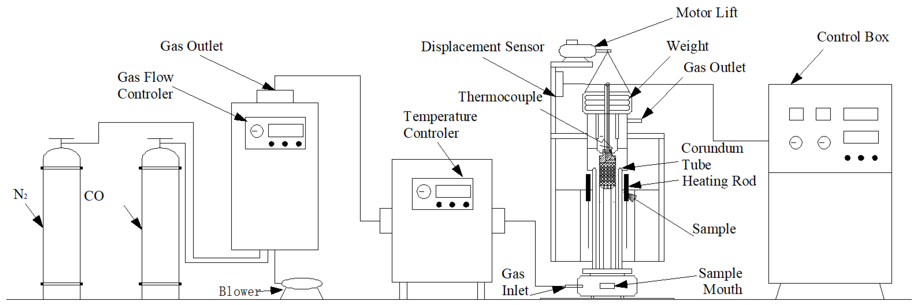
Figure 2.
Diagram of raw materials charging.
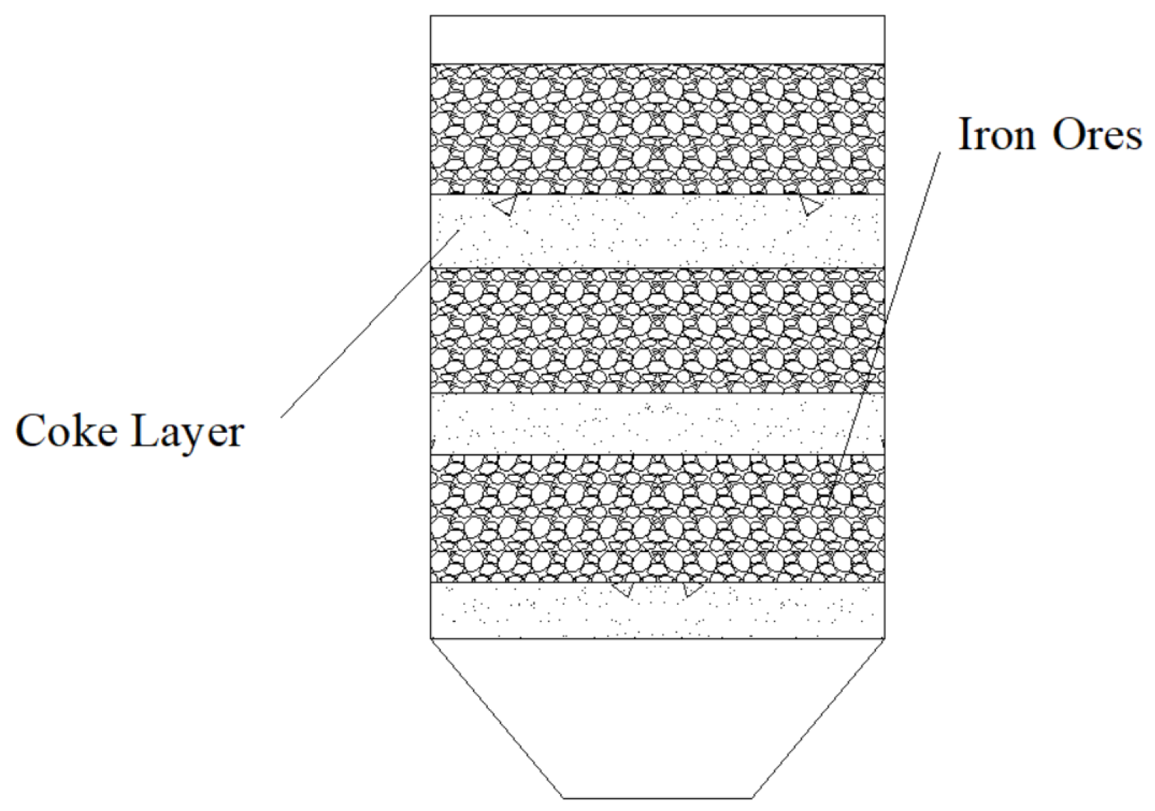
Figure 3.
Experimental conditions of the temperature and gas composition.
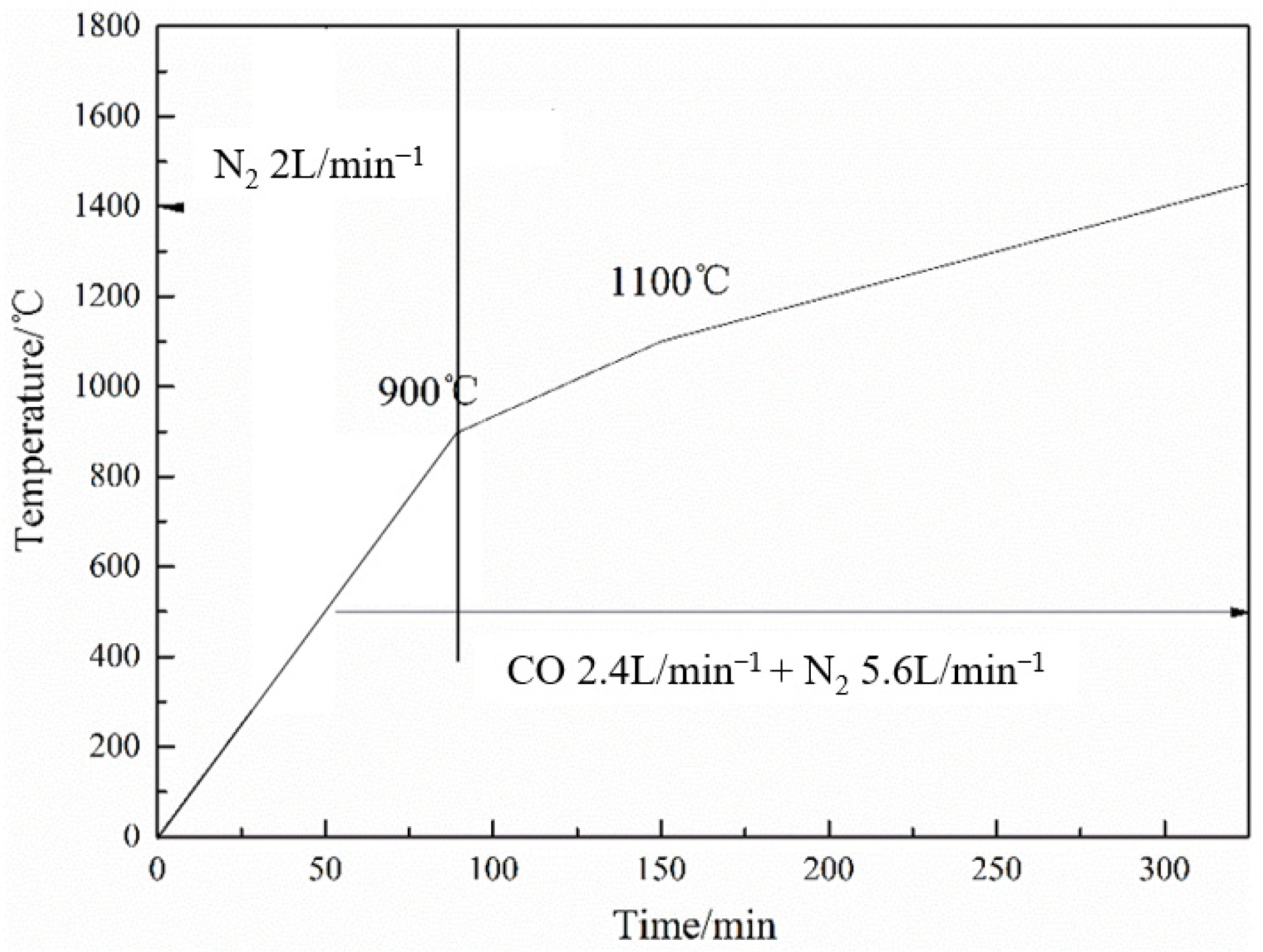
Figure 4.
Relationship between pressure drop and temperature.
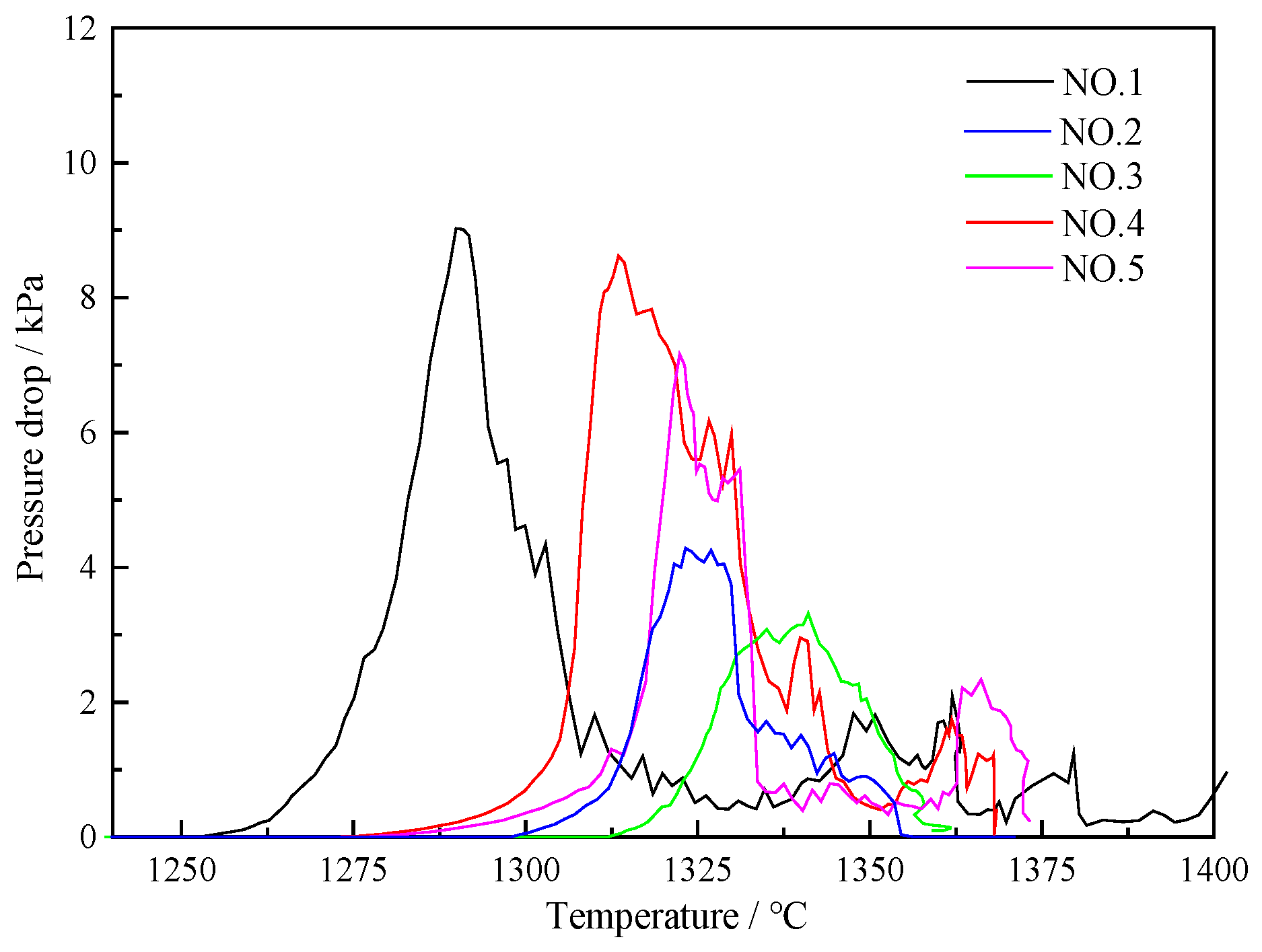
Figure 5.
Relationship between shrinkage rate and temperature.

Figure 6.
Photo of dissected graphite crucible.
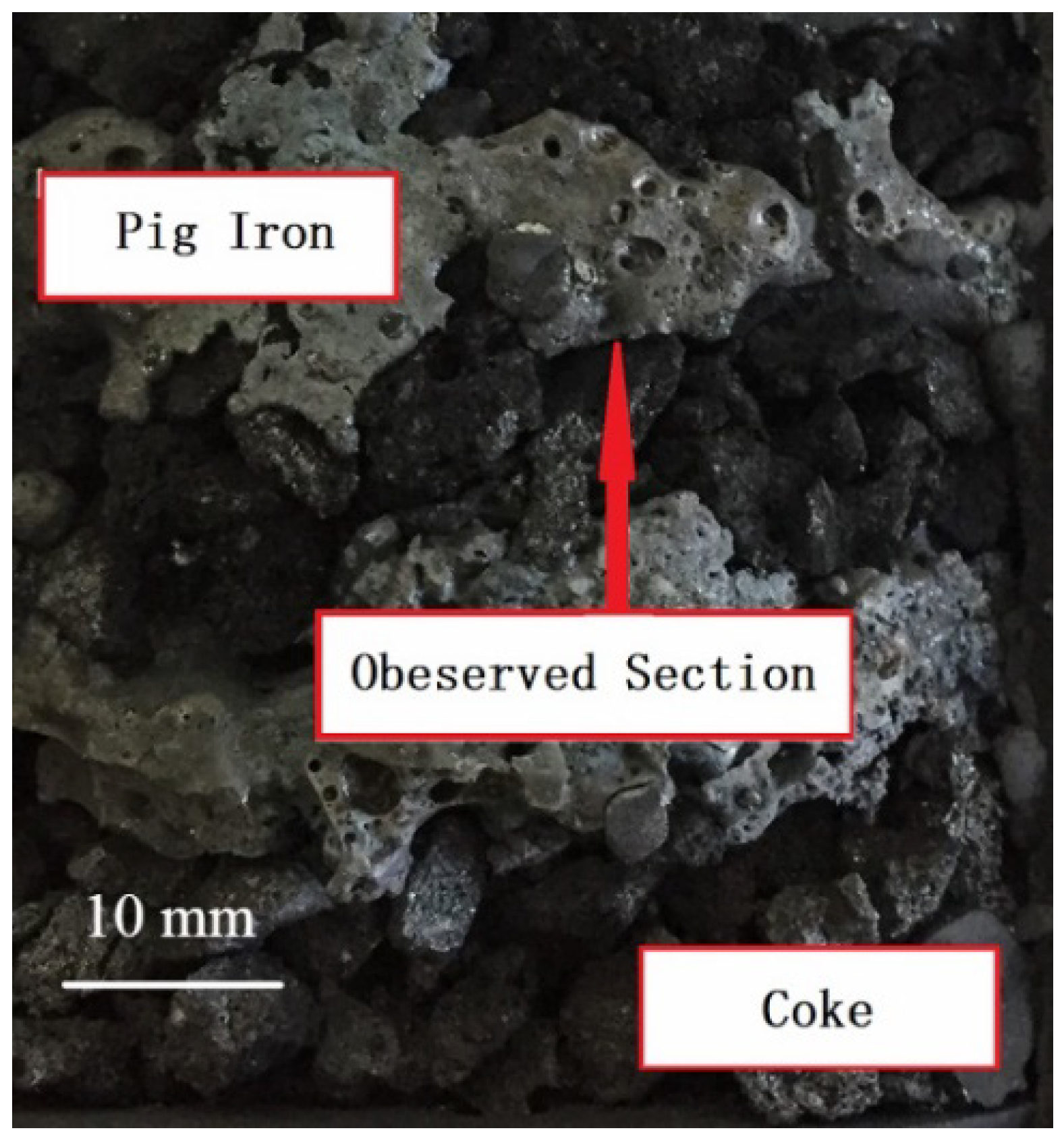
Figure 7.
Cross section of the observed section. (a) Thickness 20 mm; (b) Thickness 30 mm; (c) Thickness 40 mm.
Figure 7.
Cross section of the observed section. (a) Thickness 20 mm; (b) Thickness 30 mm; (c) Thickness 40 mm.
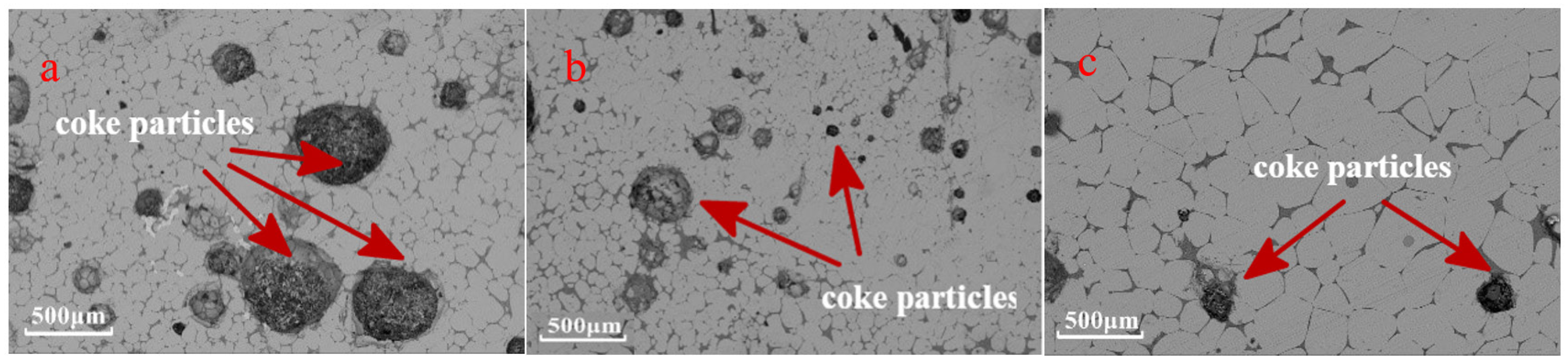
Figure 8.
Schematic diagram of coke windows.
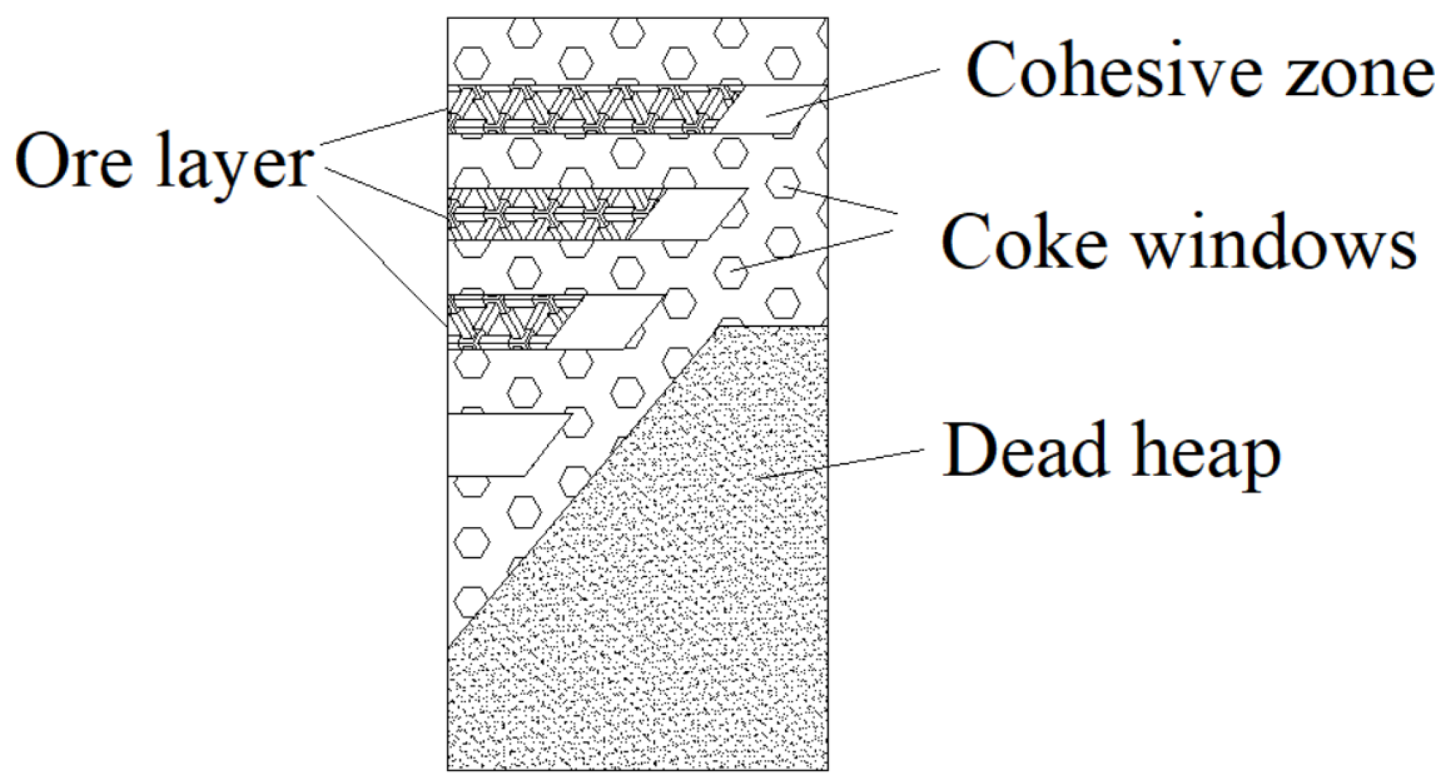
Figure 9.
Comparison between measurement results and calculation results of Equation (7).
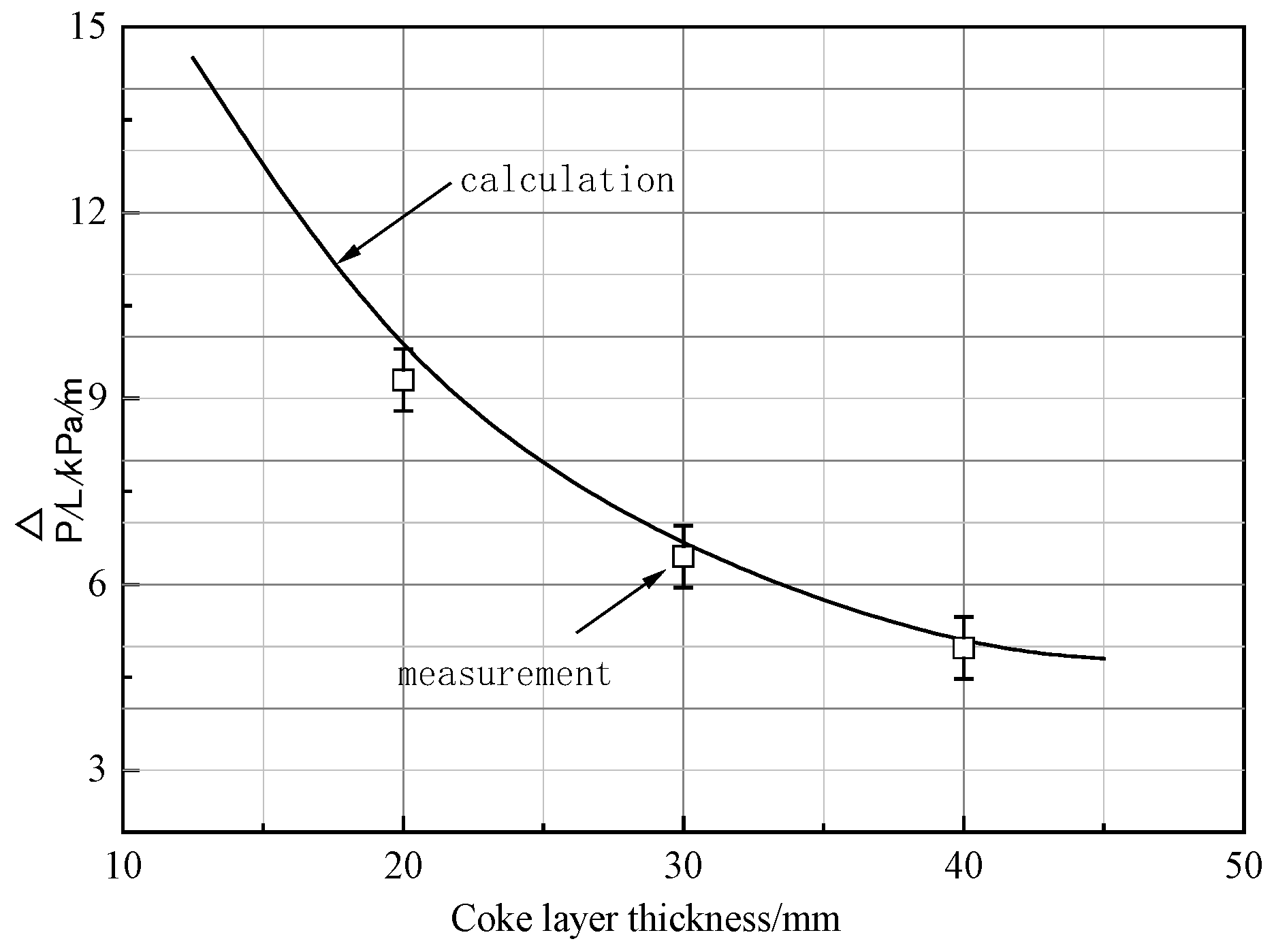
Figure 10.
Relationship between the S value and coke layer thickness.

Table 1.
Chemical composition of raw materials, %.
| Form | T[Fe] | FeO | SiO2 | CaO | Al2O3 | MgO | TiO2 | MnO |
|---|---|---|---|---|---|---|---|---|
| S-1 | 58.52 | 9.33 | 4.85 | 9.04 | 1.69 | 1.47 | 0.11 | 0.22 |
| P-1 | 66.53 | 0.32 | 2.02 | 1.49 | 0.59 | 0.16 | 0.04 | 0.13 |
| O-1 | 63.39 | 0.48 | 3.14 | 0.04 | 1.25 | 0.06 | 0.04 | 0.13 |
| O-2 | 62.47 | 0.32 | 2.96 | 0.04 | 1.26 | 0.05 | 0.04 | 0.27 |
Table 2.
Quality of coke, %.
| Index | M40 | CSR | Ms | A | S | C |
|---|---|---|---|---|---|---|
| coke | 86.19 | 65.35 | 47.6 | 12.8 | 0.98 | 85.24 |
Table 3.
Experimental conditions of the materials charging.
| No. | Coke Layer Thickness/mm | Packed Bed Thickness mm | Furnace Burden |
|---|---|---|---|
| ① | 20 | 104.2 | 65% S-1 + 20% P-1 + 15% O-1 |
| ② | 30 | 172.5 | 65% S-1 + 20% P-1 + 15% O-1 |
| ③ | 40 | 241.0 | 65% S-1 + 20% P-1 + 15% O-1 |
| ④ | 20 | 104.5 | 65% S-1 + 20% P-1 + 15% O-2 |
| ⑤ | 40 | 248.4 | 65% S-1 + 20% P-1 + 15% O-2 |
Table 4.
Molten-metal dripping properties of furnace burden with different coke layer thickness.
| T10/°C | T40/°C | ΔT | T40/°C | Pmax | Td/°C | S/kPa·°C | |
|---|---|---|---|---|---|---|---|
| ① | 1191 | 1278 | 87 | 1285 | 9322 | 1403 | 1007 |
| ② | 1170 | 1271 | 101 | 1296 | 6559 | 1364 | 445 |
| ③ | 1169 | 1278 | 109 | 1289 | 4970 | 1347 | 644 |
| ④ | 1183 | 1282 | 99 | 1285 | 11,090 | 1360 | 936 |
| ⑤ | 1165 | 1280 | 115 | 1300 | 10,884 | 1365 | 624 |
Disclaimer/Publisher’s Note: The statements, opinions and data contained in all publications are solely those of the individual author(s) and contributor(s) and not of MDPI and/or the editor(s). MDPI and/or the editor(s) disclaim responsibility for any injury to people or property resulting from any ideas, methods, instructions or products referred to in the content. |
© 2024 by the authors. Licensee MDPI, Basel, Switzerland. This article is an open access article distributed under the terms and conditions of the Creative Commons Attribution (CC BY) license (https://creativecommons.org/licenses/by/4.0/).
Share and Cite
MDPI and ACS Style
Wang, Y.-H.; Du, P.; Diao, J.; Xie, B.; Zhu, M.-H. Study on the High-Temperature Interaction between Coke and Iron Ores with Different Layer Thicknesses. Materials 2024, 17, 1358. https://doi.org/10.3390/ma17061358
AMA Style
Wang Y-H, Du P, Diao J, Xie B, Zhu M-H. Study on the High-Temperature Interaction between Coke and Iron Ores with Different Layer Thicknesses. Materials. 2024; 17(6):1358. https://doi.org/10.3390/ma17061358
Chicago/Turabian StyleWang, Yong-Hong, Ping Du, Jiang Diao, Bing Xie, and Ming-Hua Zhu. 2024. "Study on the High-Temperature Interaction between Coke and Iron Ores with Different Layer Thicknesses" Materials 17, no. 6: 1358. https://doi.org/10.3390/ma17061358
Note that from the first issue of 2016, this journal uses article numbers instead of page numbers. See further details here.