Article

Study on the Oxidation Behavior of TiB2-CeO2-Modified (Nb,Mo,Cr,W)Si2 Coating on the Surface of Niobium Alloy

1
School of Materials Science and Engineering, Central South University, Changsha 410083, China
2
State Key Laboratory of Special Rare Metal Materials, Northwest Rare Metal Materials Research Institute, Shizuishan 753000, China
3
Powder Metallurgy Research Institute, Central South University, Changsha 410083, China
4
School of Minerals Processing and Bioengineering, Central South University, Changsha 410083, China
*
Author to whom correspondence should be addressed.
Materials 2024, 17(21), 5244; https://doi.org/10.3390/ma17215244
Submission received: 19 September 2024 / Revised: 8 October 2024 / Accepted: 16 October 2024 / Published: 28 October 2024
(This article belongs to the Special Issue Research on Performance Improvement of Advanced Alloys)

Abstract

:
A novel TiB2-CeO2-modified (Nb,Mo,Cr,W)Si2 coating was prepared on a Nb-5W-2Mo-1Zr alloy substrate using two-step slurry sintering and halide-activated pack cementation to address the limitations of a single NbSi2 coating in meeting the service requirements of niobium alloys at elevated temperatures. At 1700 °C, the static oxidation life of the coating exceeded 20 h, thus indicating excellent high-temperature oxidation resistance. This was due to the formation of a TiO2-SiO2-Cr2O3 composite oxide film on the coating surface, which, due to low oxygen permeability, effectively prevented the inward infiltration of oxygen. Additionally, the dense structure of the composite coating further enhanced this protective effect. The composite coating was able to withstand over 1600 thermal shock cycles from room temperature to 1700 °C, and its excellent thermal shock performance could be attributed to the formation of MoSi2, CrSi2, and WSi2 from elements such as Mo, Cr, and W, which were added during modification. In addition to adjusting the difference in thermal expansion coefficients between the layers of composite coatings to reduce the thermal stress generated by thermal shock cycles, the formation of silicide compounds also improved the overall fracture toughness of the coating and thereby improved its thermal shock resistance.

1. Introduction

Nickel-based high-temperature alloys with a maximum working temperature of around 1300 °C are typically used in traditional aerospace aircraft engines and engine blades as structural materials. However, the current service temperature of new-generation aircraft and other components in aerospace engineering is much higher than 1300 °C and can reach as high as 1600–1800 °C. This necessitates the use of new materials with better high-temperature mechanical properties [1]. Nb-based alloys are high-temperature structural materials that are commonly used in the new generation of aerospace applications because of their high melting point (2468 °C), low density (8.57 g/cm3), good processing performance due to enhanced plasticity, and excellent high-temperature mechanical properties [2,3,4]. However, the poor resistance of Nb to oxidation at high temperatures results in severe oxidation above 600 °C. The oxidation product Nb2O5 is loose and porous, which can cause the rapid oxidation of the niobium alloy substrate due to its ineffectiveness in preventing the inward diffusion of oxygen. This is a serious disadvantage that restricts the further application of niobium alloys in the field of high-temperature applications [5].
Various approaches have been investigated to enhance the high-temperature oxidation resistance of niobium alloys, among which the three main routes are the alloying [6], grain refinement, and surface protective coating methods [7]. The alloying method refers to the addition of Si, Al, Cr, Ti, Hf, and various rare-earth elements to Nb substrates [8], thus forming a dense oxide film by reacting with oxygen and thereby protecting the substrate. The grain refinement method can accelerate the preferential oxidation of alloying elements and is generally used for niobium alloys after alloying. These two methods are able to improve the high-temperature oxidation resistance of niobium alloys to a certain extent; however, the substantial addition of antioxidant alloy elements often leads to rapid deterioration of the mechanical properties of niobium alloys. Consequently, balancing processing performance with complete oxidation resistance in high-temperature environments above 1300 °C remains challenging, thus limiting the application potential of the existing niobium alloys [9]. In the surface protective coating method, a protective barrier is prepared on the surface of the niobium alloy substrate, which can protect the substrate at high temperatures by effectively preventing the inward diffusion of oxygen. Presently, the various high-temperature oxidation-resistant coatings for niobium alloys include precious metal coatings, oxide ceramic coatings, heat-resistant alloy coatings, aluminide coatings, silicide coatings, etc. [10,11,12,13,14,15,16], among which silicide coatings are the most widely used. Due to the semi-molten state of SiO2 and its fluidity at high temperatures, it can repair coating cracks by flowing into the coating, thus endowing certain self-healing properties [17,18]. This coating system is significant in the high-temperature protection of niobium alloys.
Among the various silicide coating systems that are similar to niobium alloys are Si-Cr-Ti(Fe) coatings [19], Si-Nb coatings [20,21], and Si-Mo coatings [22,23]. Presently, the Si-Nb coating is the most widely used, with NbSi2 as the main phase of the coating. However, the service requirements at higher temperatures cannot be met by single NbSi2 coatings. Additionally, the mismatch in the thermal expansion coefficient between the coating and the substrate can easily cause defects, such as cracks, which can ultimately lead to failure in high-temperature thermal shock environments. Therefore, doping the NbSi2 coating is necessary [24,25,26] for the preparation of composite coatings with excellent high-temperature protection abilities and resistance to cyclic thermal shock. TiB2 and MoSi2 both have high melting points and excellent high-temperature oxidation resistance [22,27]. CeO2 can promote the thickness of the NbSi2-MoSi2 coating and improve grain refinement [2]. Yue et al. [28] have prepared a MoSi2/WSi2 compound coating on a Nb-Ti-Si-based alloy, in which WSi2 has a Si storage function, thereby improving the service life of the coating. Zhang [29] has prepared a MoSi2-CrSi2-Si3N4 composite coating on a Mo substrate and found that the Cr element inhibits the diffusion of Si during oxidation and the formation of a volatilizable MoO3 phase. The mismatch in the thermal expansion coefficient between NbSi2 and niobium alloy substrates can be reduced by introducing CeO2, TiB2, MoSi2, CrSi2, and WSi2.
Therefore, in this study, a TiB2-CeO2-modified (Nb,Mo,Cr,W)Si2 coating was prepared on a Nb-5W-2Mo-1Zr alloy substrate using two-step slurry sintering and halide-activated pack cementation. The formation mechanism, static oxidation resistance, thermal shock resistance, and microstructural properties of the coating at 1700 °C were studied.

2. Experimental Procedure

2.1. Nb Alloy Substrate Preparation

Nb521 alloy (Nb-5W-2Mo-1Zr, wt.%, Ningxia Orient Tantalum Industry Co., Ltd., Ningxia, China) was used as the substrate in this study. Firstly, 70 mm × 7.5 mm × 0.8 mm niobium sheets were cut from the substrate, and a hole with a diameter of 3 mm was drilled at one end of each niobium sheet for hanging in the sintering furnace. Each specimen of the niobium sheet was grounded and polished, followed by ultrasonication in NaOH solution at 100 °C for 10 min (pH = 13) for the removal of oil. Each specimen was then cleaned in distilled water and subsequently ultrasonically cleaned for 10 min at 80–90 °C in a mixed solution of HNO3, HCl, and deionized water at a pH value of approximately 1 to remove the oxide layer from the sample surface. Ultrasonic cleaning with alcohol was used for final cleaning of the Nb521 specimens.

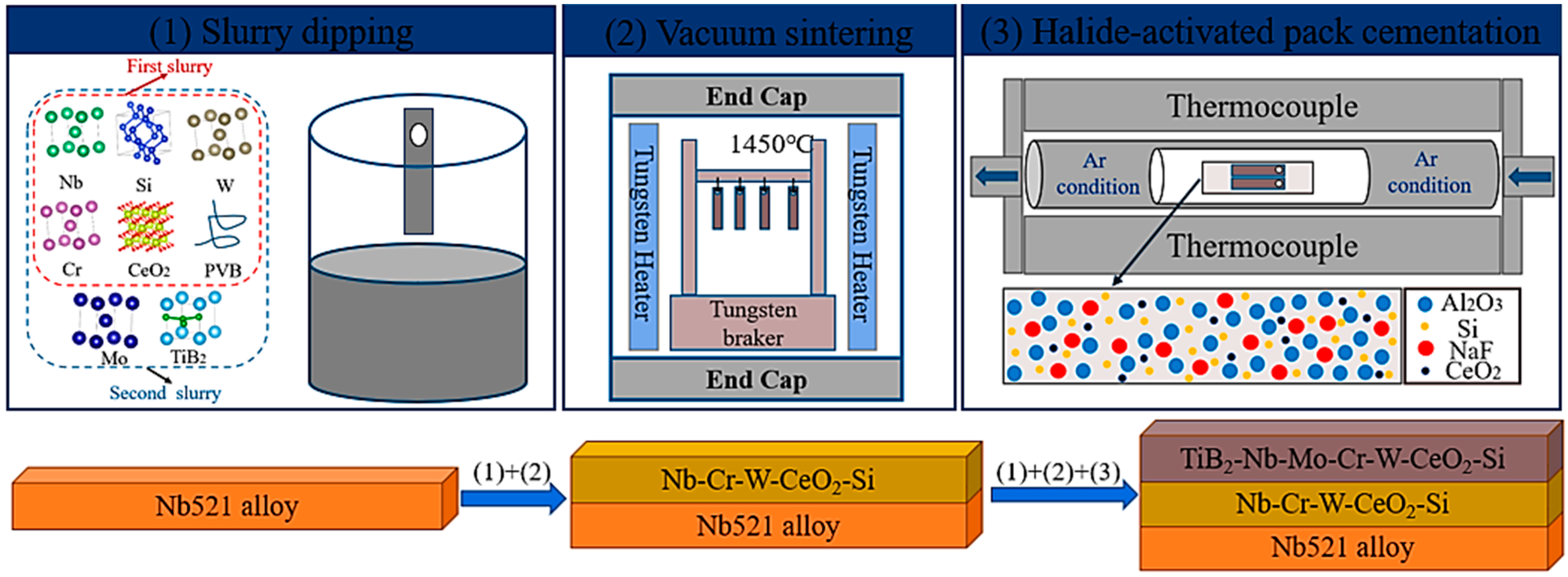
2.2. Preparation of the Coating

The preparation process of the TiB2-CeO2-modified (Nb,Mo,Cr,W)Si2 coating is shown in Figure 1. Two-step slurry sintering and halide-activated pack cementation were used to prepare the TiB2-CeO2-modified (Nb,Mo,Cr,W)Si2 coating on the Nb521 substrate. Nb-Cr-W-Si and TiB2-Nb-Mo-Cr-W-Si were the main solutes of the slurries used for the two dippings, and anhydrous ethanol was used as the solvent. In addition, during the sintering process, PVB and extremely trace amounts of CeO2 (to improve the uniformity of the coating structure) were also added. The purity of all of the powders was over 99.9%, and all of the reagents were of AR grade. The ratio of solute (g) to ethanol solvent (mL) was selected as 1:0.9. The slurry was placed in a planetary mill (ZrO2 as the ball milling medium) before use and fully grounded for 8 h at 250 rpm. In order to ensure that the surface of the slurry on the substrate was uniform and that the thickness was moderate, each slurry dipping was conducted in three intervals, with each lasting 5–8 s. After each dipping, the Nb521 substrates were dried at 60 °C for 12 h and sintered in a vacuum sintering furnace (1 × 10⁻³ Pa) at 1450 °C for 120 min after heating at a rate of 10 °C/min. The two layers of the coating formed by the two dippings and by the sintering were CeO2-Nb-Cr-W-Si and CeO2-TiB2-Nb-Mo-Cr-W-Si, respectively. After two-step slurry sintering, the sample was embedded into a uniform mixture of Al2O3 (purity 99.9%), NaF powder (purity 99.9%), CeO2 powder, and Si (purity 99.9%) and maintained at 1200 °C in an argon-protected tube furnace in order to facilitate the formation of silicide components in the surface coating of the sample.

2.3. Characterization of Microstructure

Phases on the coating were analyzed using X-ray diffraction (XRD, D/Max 2500, Rigaku Corporation, Tokyo, Japan) employing a Cu Kα radiation of 30 kV and 100 mA. For morphological evaluation of the coating and performance of qualitative and semi-quantitative analysis on the surface and cross-section of the coating, we employed a scanning electron microscope (SEM, sirion200, FEI Company, Hillsboro, OR, USA) equipped with an energy dispersive spectrometer (EDS). Electron probe microanalysis (EPMA, JXA-8230, Japan Electronics Co., Ltd., Tokyo, Japan) equipped with wavelength dispersive spectroscopy (WDS) was used to analyze the morphology of coating cross-sections and quantitative analysis of the composition. High-resolution transmission electron microscopy (HRTEM, Titan G2 60-300, FEI Company, Hillsboro, OR, USA) was used to characterize the crystal structure of the main coating phase.

2.4. Oxidation Resistance and Thermal Shock Resistance Tests of the Coating

A self-developed high-temperature oxidation experimental setup was employed to carry out the static oxidation resistance test and high-temperature thermal shock resistance test of the coating. In the static antioxidant test, the coating on both ends of the specimen was polished off and clamped to introduce a high-current circuit. Subsequently, the specimen was heated to the oxidation temperature (1700 °C) at a rate of 600 °C/min using the Joule effect and maintained at this temperature for the entire duration of the test. For the high-temperature thermal shock resistance test of the coating, one thermal shock cycle consisted of heating the sample from room temperature to 1700 °C within 15 s (the heating method used during the high-temperature thermal shock resistance test was the same as that used during the static oxidation resistance test), holding the temperature for 10 s, and then cooling from 1700 °C to room temperature within 10 s using cooling water. This was followed by holding at room temperature for 5 s before reheating. The number of thermal shock resistance cycles of the coating was recorded automatically by the system. Both the static oxidation test and thermal shock test were carried out in a static air environment.

3. Result and Discussion

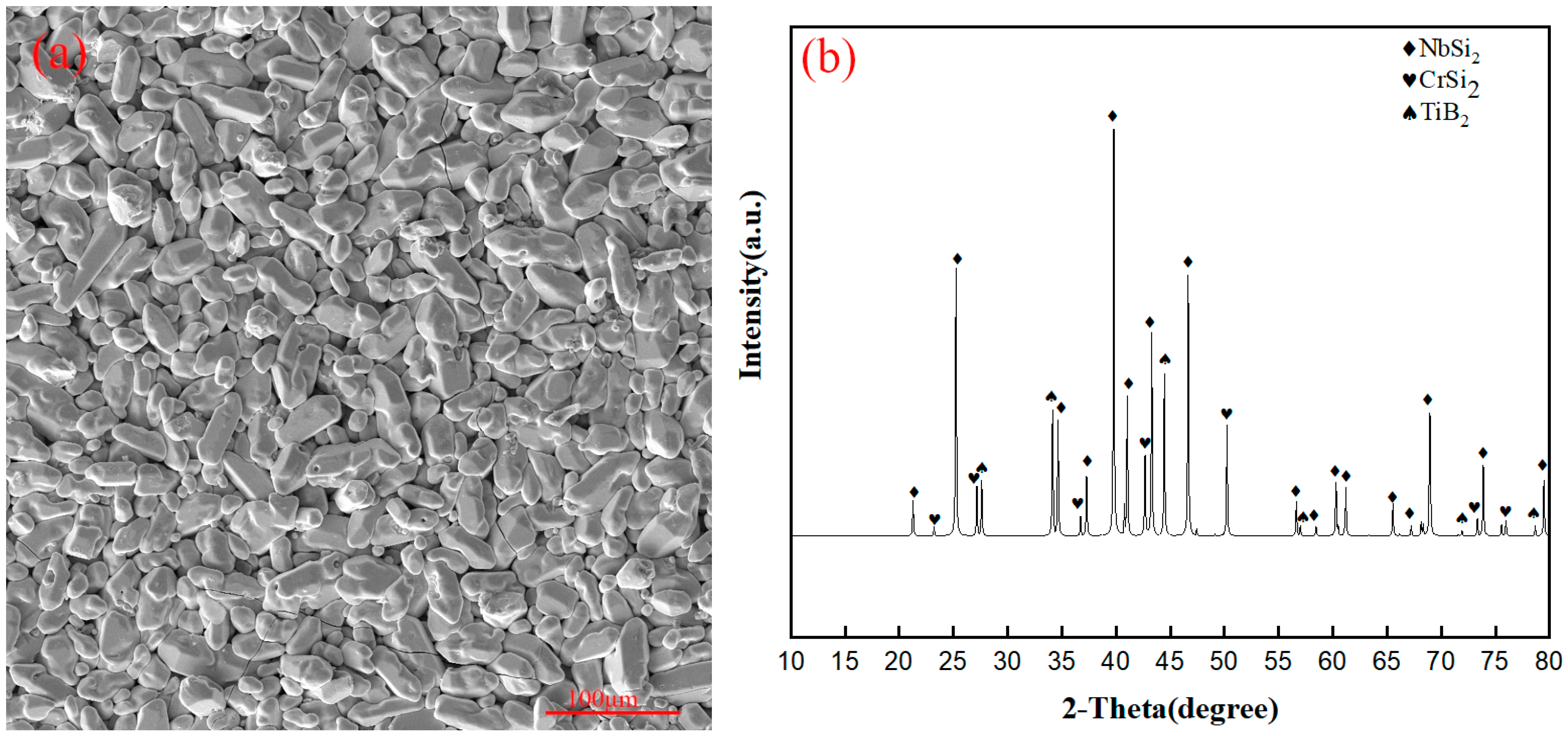
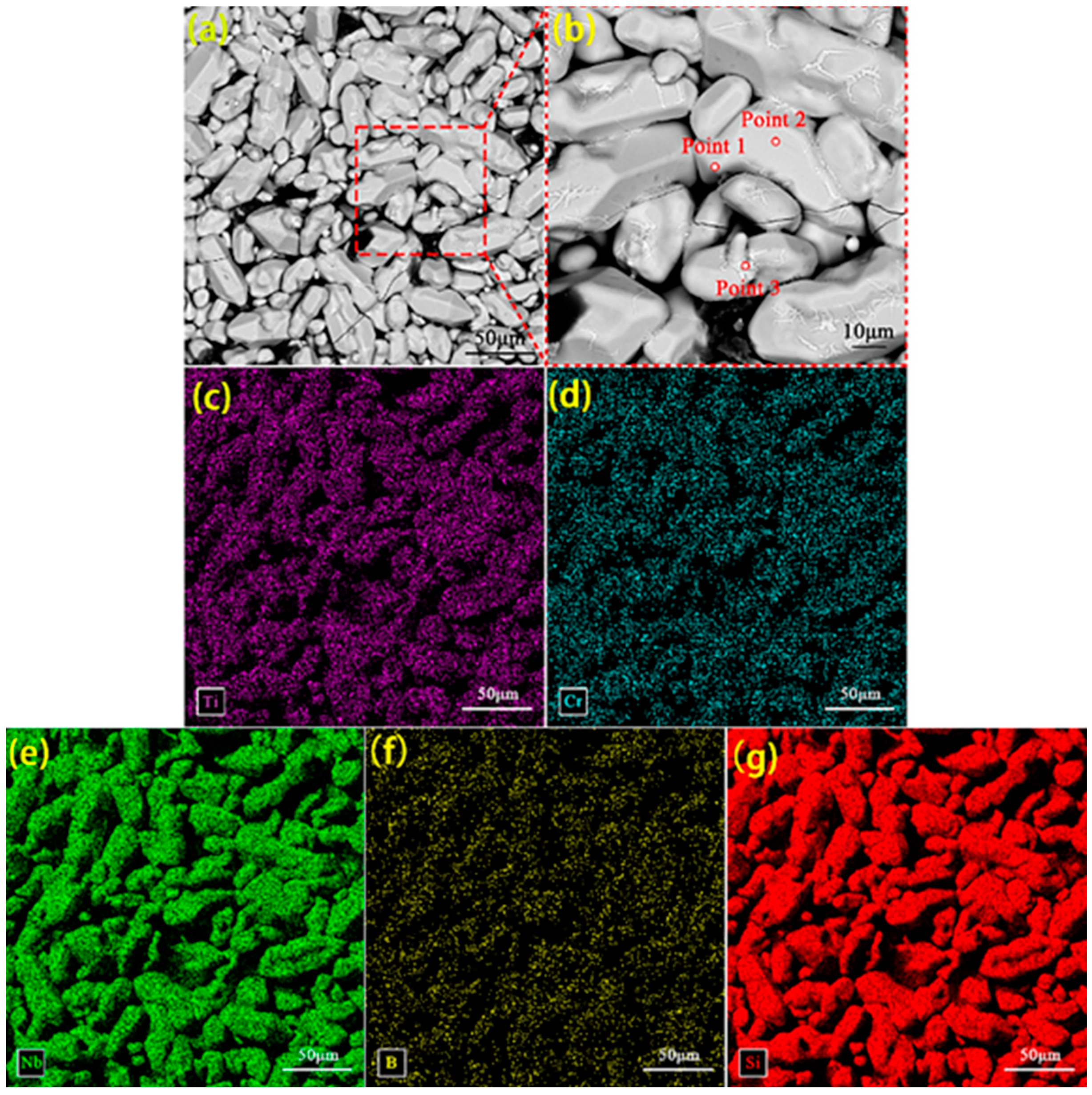
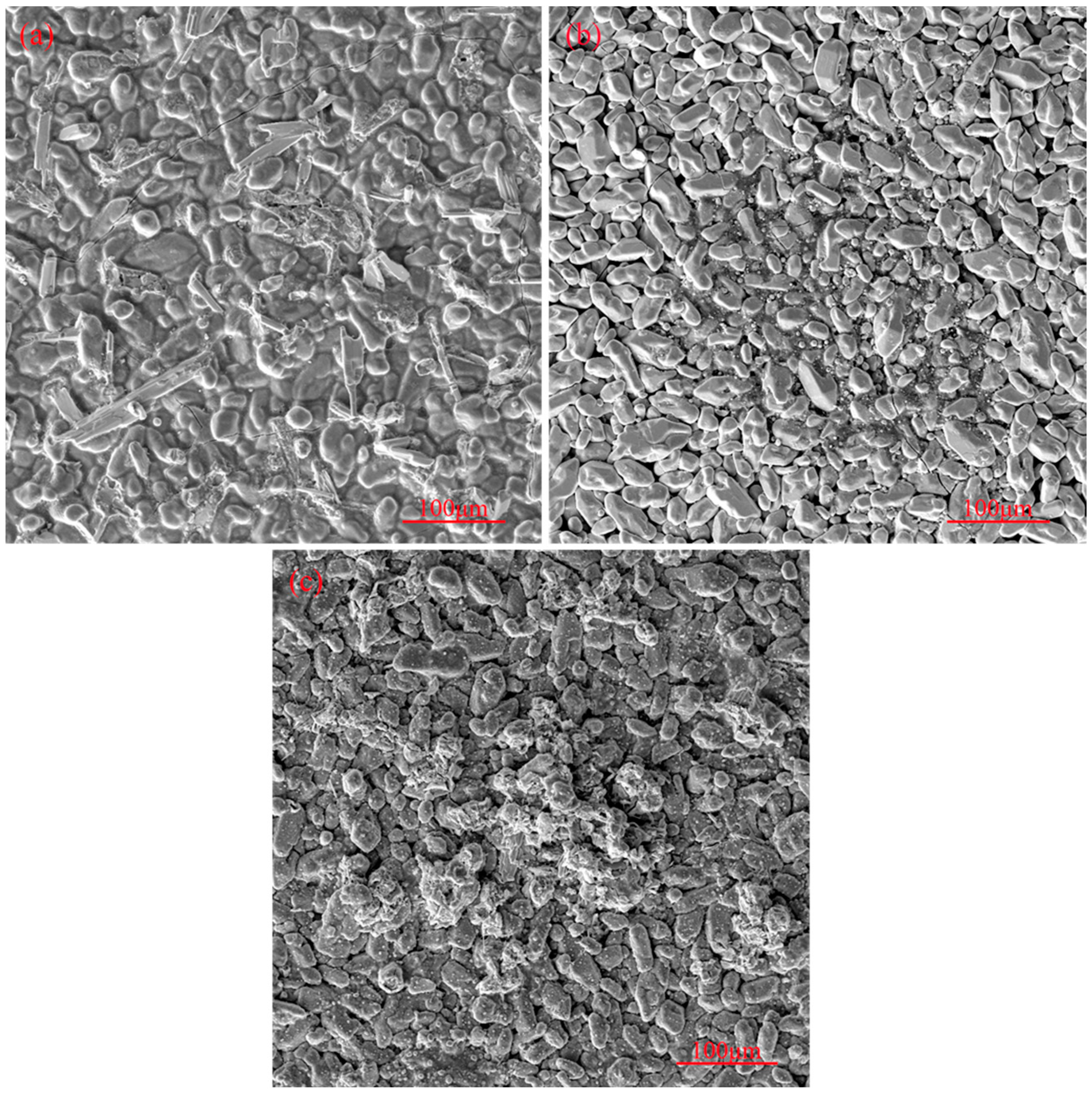
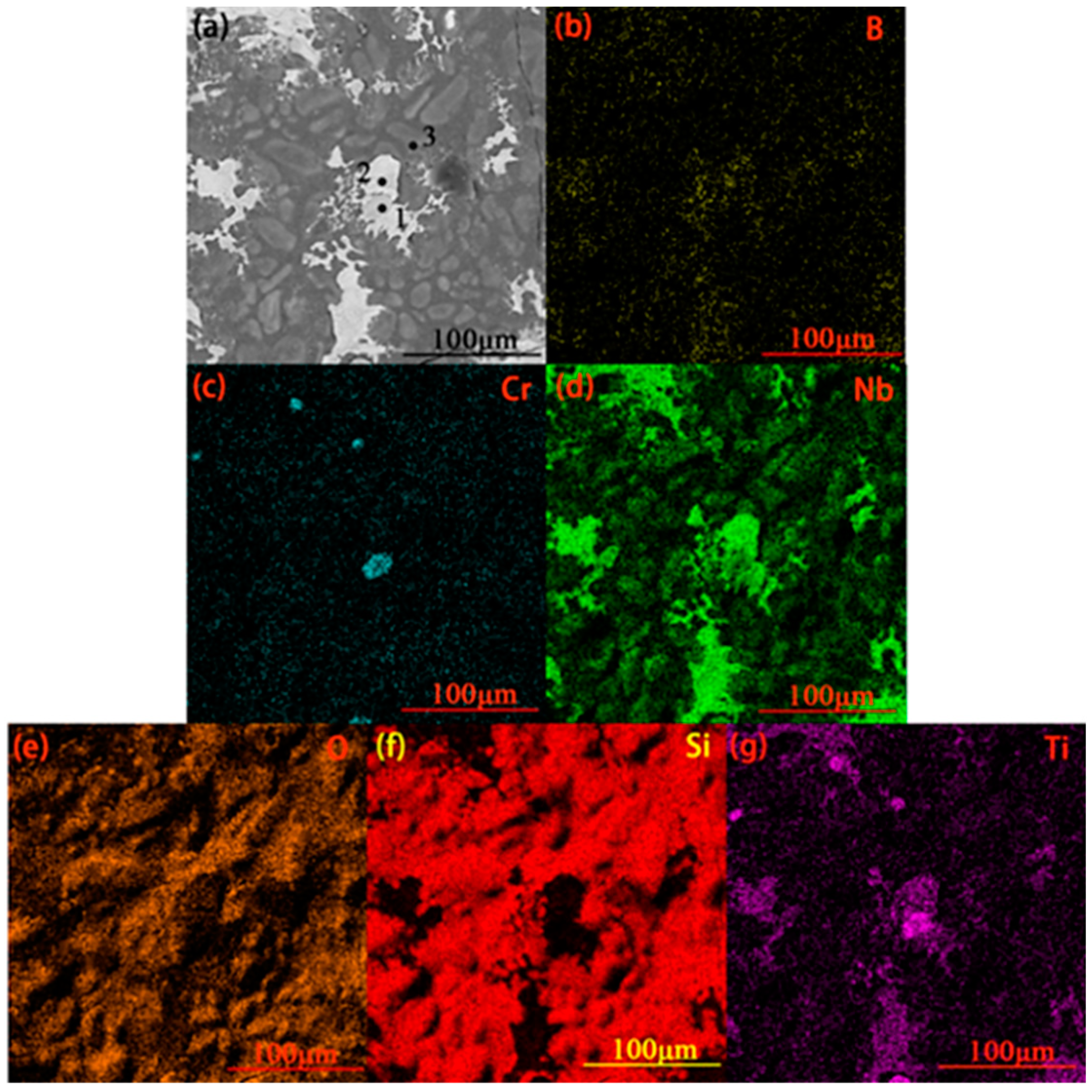
3.1. Surface Morphology of the Original Coating

The surface morphology of the original coating, along with its XRD analysis results, is shown in Figure 2. The surface composition of the original coating can be seen to contain NbSi2, CrSi2, and TiB2, with the overall composition being uniform with only a few microcracks.
Figure 3 shows the surface EDS scan of the original coating surface. The EDS point scan results of each micro-region shown in Figure 3b are given in Table 1. Figure 3 indicates the presence of elements such as Ti, Cr, and B on the coating surface. Combined with the point scan results given in Table 1, Si and Nb can be seen to be the main components of the coating surface from Figure 3 with the ratio of (Nb + Cr) to Si ≈ 1:2. Therefore, NbSi2 should be the main component of the coating surface, with CrSi2 being the minor part. TiB2 is responsible for the element Ti (TiB2 is a modified additive during coating sintering and does not participate in the reaction during vacuum sintering), so a small amount of TiB2 is also present in the coating surface.

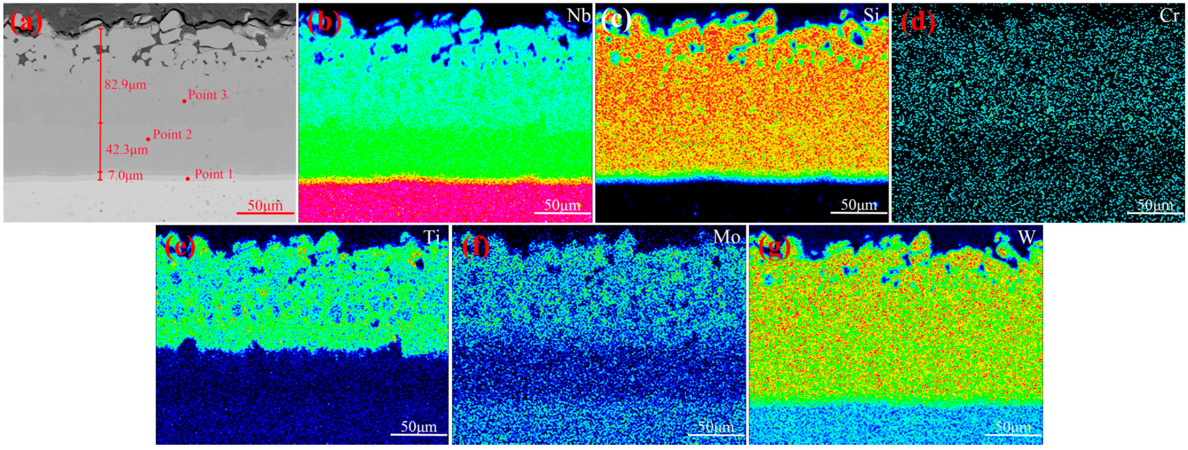
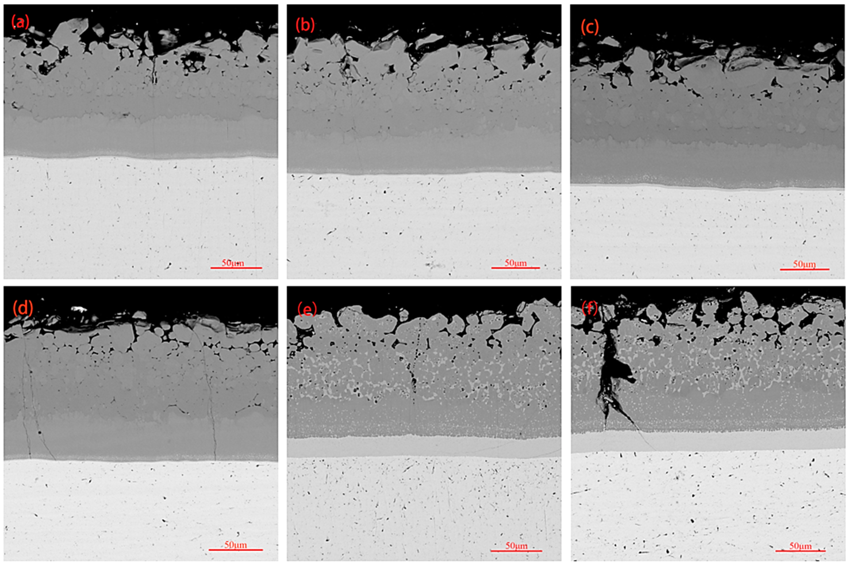
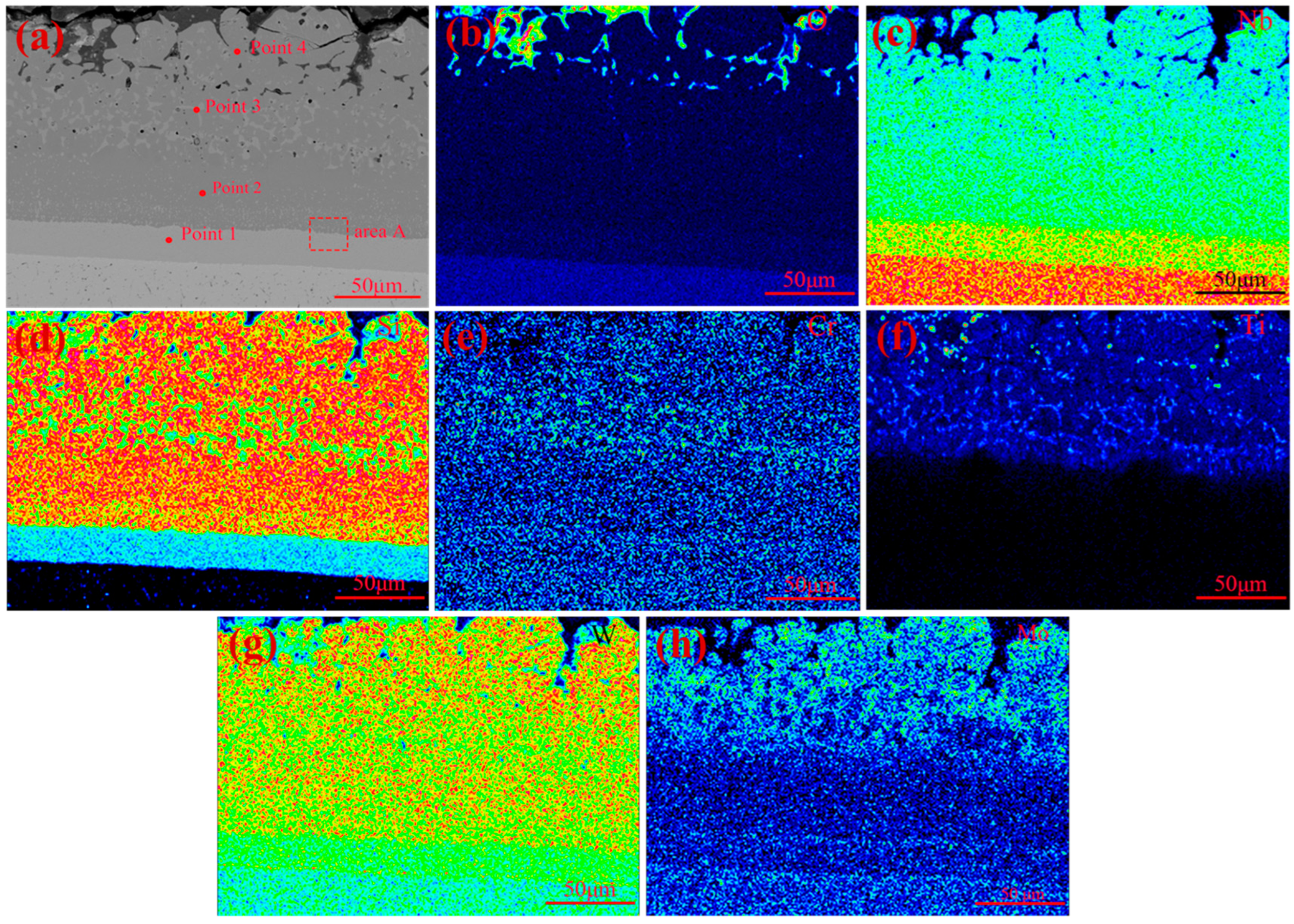
3.2. The Cross-Sectional Morphology and Mechanism of Formation of the Original Coating

The cross-sectional morphology, along with surface scanning results of the original coating, can be seen in Figure 4. A dense and overall uniform coating, with only a small number of pores, can be inferred from Figure 4a, which can be attributed to the incorporation of trace amounts of CeO2 and uniform slurry. The coating consisted of a diffusion layer and a main layer, which was further divided into two layers. The thickness of the diffusion layer was 7.0 μm, while the thicknesses of the inner main layer and outer main layer were 42.3 μm and 82.9 μm, respectively. According to Figure 4b–g, the elements Nb, Si, Cr, and W were distributed throughout the entire coating, while the elements Mo and Ti were distributed in the outer main layer of the coating. Table 2 shows the point scan results of the micro-area in Figure 4a. According to Table 2, during the sintering process, the elements Mo and Zr from the niobium alloy substrate diffused into the coating, and the amount of diffusion decreased with increasing distance from the substrate. However, for the element Mo, the content in the outer main layer is higher than that in the diffusion layer due to the addition of Mo during the second slurry sintering process, which is mainly distributed in the outer main layer. The content of W gradually increased toward the interior, as it was added during both sintering processes. Ti, Cr, and a small amount of Ce were distributed in the main layer of the coating, with their contents in the outer main layer being higher than those in the inner main layer. The addition of the Ce element is beneficial for promoting grain refinement and the densification of the coating [2]. The ratio of Nb to Si content in the diffusion layer was about 5:3, and it also contained small amounts of Mo and W, inferring that Nb5Si3 and low silicides of Mo/W were its main phases. The elemental ratio of (Nb, W, Cr, Mo):Si in the main coating was found to be 1:2, implying that NbSi2 and high silicides of Mo/W/Cr were its main phases. Moreover, a small amount of Ti, mainly existing in the form of TiB2, was also present in the outer main layer.
Based on the above conclusions and literature reports [19,22,30,31], it can be inferred that the following reactions primarily occur in the coating during the two-step slurry sintering process.
3Si(l) + 5Nb(s) → Nb5Si3(s)
7Si(l) + Nb5Si3(s) → 5NbSi2(s)
Si(l) + Nb(s) → NbSi2(s)
2Si(l) + Mo(s) → MoSi2(s)
2Si(l) + Cr(s) → CrSi2(s)
2Si(l) + W(s) → WSi2(s)
According to HSC calculations, the Gibbs free energies of reactions (1), (2), (3), (4), (5), and (6) at 1450 °C were −42.041 kcal/mol, −1.204 kcal/mol, −13.455 kcal/mol, −14.931 kcal/mol, −10.481 kcal/mol, and −9.305 kcal/mol, respectively. This indicates that all of the above reactions can take place spontaneously at 1450 °C. With Nb and Si as the main components of the slurry and reaction (1) having the minimum Gibbs free energy during the sintering process, Nb5Si3 (diffusion layer) is generated first, followed by reaction (2) to generate NbSi2 (main layer) as sintering proceeds. Other components present in the coating, such as Mo, W, and Cr, also react with Si in the main layer. Based on the Gibbs free energy comparison, the order of generation is as follows: MoSi2, CrSi2, and WSi2. Therefore, the coating structure was as follows: diffusion layer (Nb5Si3/low silicides of Mo and W) + inner main layer ((Nb,W,Mo,Cr)Si2) + outer main layer ((Nb,W,Mo,Cr)Si2/TiB2).

3.3. High-Temperature Oxidation Behavior of Coatings

The static oxidation life of the coating exceeded 20 h at 1700 °C, and morphology analysis of the coatings was carried out after varying oxidation times of 0.5 h, 1 h, 5 h, 10 h, 15 h, and 20 h.
The surface morphology of the coating after 1 h, 10 h, and 20 h of oxidation is shown in Figure 5. After each oxidation stage, a small number of non-film-forming agglomerates, which increase with increasing oxidation time, can be seen on the surface, as indicated in Figure 5. A small number of tiny cracks started to appear on the coating surface from 1 h, as seen in Figure 5a, but the cracks did not increase significantly during the subsequent oxidation process. After an oxidation period of 10 h, some small particles started to appear on the coating surface, as can be seen in Figure 5b. As shown in Figure 5c, after an oxidation time of 20 h, more particles appeared on the coating surface, and part of the coating structure exhibited oxidization and damage.
Figure 6 shows the surface scan of the coating after 1 h of oxidation, and the point scan results of the micro-area shown in Figure 6a are presented in Table 3. According to Figure 6d,f, the white part of the surface after oxidation of the coating primarily contains the elements Nb and Ti, while the black part is constituted mainly by the element Si. According to Figure 6c, only a very small area on the coating surface is concentrated with Cr, thus indicating an extremely small distribution of Cr. Combining the surface scan results of elemental oxygen and the point scan results given in Table 3, the main components of the white part can be seen to be Nb2O5 and TiO2, along with a small amount of SiO2 and a very small amount of Cr2O3. The main component of the black part is SiO2, with a small amount of Nb2O5.
Cross-sectional morphologies of the coating after oxidation for 0.5 h, 1 h, 5 h, 10 h, 15 h, and 20 h are shown in Figure 7, showing that the cross-sectional morphology of the coatings up to 10 h of oxidation is similar to the cross-sectional morphology of the original coating, barring the appearance of a small number of microcracks on the cross-section of the coatings after 10 h of oxidation. Cross-sectional morphologies of the coatings after oxidation times of 15 h and 20 h were in the same form. A significant increase in the diffusion layer thickness of the coatings took place, and many white dispersed phases containing low silicides appeared on the main layer. Large cracks penetrating the entire main layer were observed in the coating after 20 h of oxidation. As the oxidation continued, oxygen penetrated the diffusion layer through the large cracks, leading to oxidation reactions. Due to the diffusion layer being primarily composed of low silicides, it quickly reacted with oxygen to cause cracks that rapidly extended to the substrate, resulting in coating failure. The appearance of large cracks throughout the entire coating indicated that the coating was about to reach its testing limit.
The surface scan results of the coating after 10 h of oxidation are shown in Figure 8, with point scan results of the micro-area in Figure 8a being shown in Table 4. As per Figure 8b and the O content in each micro-area shown in Table 4, the O element mainly exists on the surface of the coating after 10 h of oxidation, with its content inside the coating being negligible. This indicates that the coating has a high density, effectively preventing inward penetration of oxygen. As indicated in Figure 8c,d and the Nb and Si contents in each micro-area shown in Table 4, the structure of the coating is still divided into the main layer and diffusion layer. The ratio of Nb to Si content in the main layer and the diffusion layer was about 1:2 and 5:3, respectively. Therefore, NbSi2 remains the main phase of the coating, while Nb5Si3 is the main phase of the diffusion layer. However, it is worth noting that more white dispersed phases can be seen in the outer main layer. The ratio of Nb to Si content in the white dispersed phase was between 1:2 and 5:3, indicating NbSi2 and Nb5Si3 to be the main components of the white dispersed phase in the main layer. The transformation from NbSi2 to Nb5Si3 occurs over an oxidation period of 10 h. According to Figure 8e–h and the content of modified elements in each micro-area shown in Table 4, it can be seen that Mo is almost absent in the coating. This may be due to the generation of MoO3 from the reaction between MoSi2 and oxygen, which evaporates at 1700 °C. The contents of Ti and Cr in the white dispersed phase of the outer main layer are much higher than those in other parts of the coating, and the W content in the coating remains basically unchanged before and after oxidation.
Based on the above analysis and surface scan results of the coating after 1 h of oxidation shown in Figure 6, as well as the corresponding micro-area point scan results, it can be concluded that the following reactions take place in the coating during the oxidation process [2,32,33,34]:
5NbSi2(s) + 7O2(g)→Nb5Si3(s) + 7SiO2(l)
4Nb5Si3(s) + 37O2(g)→12SiO2(l) + 10Nb2O5(s)
4CrSi2(s) + 11O2(g)→2Cr2O3(s) + 8SiO2(l)
2TiB2(s) + 5O2(g)→2TiO2(s) + 2B2O3(l)
2MoSi2 + 7O2(g)→2MoO3(g) + 4SiO2(l)
WSi2 + 3.5O2(g)→WO3(g) + 2SiO2(l)
According to HSC calculations, the Gibbs free energies for reactions (7), (8), (9), (10), (11), and (12) at 1700 °C are −133.83 kcal/mol, −99.60 kcal/mol, −116.08 kcal/mol, −111.37 kcal/mol, −84.69 kcal/mol, and −84.24 kcal/mol, respectively. These values indicate the spontaneity of the above reactions at 1700 °C.
Though the Gibbs free energy of the reaction between TiB2 and oxygen was not the lowest, it nevertheless comes into contact with oxygen first because it is located in the outer main layer of the coating. TiO2 is generated in the reaction, which covers the surface of the coating, and, due to its low melting point of 450 °C, B2O3 quickly evaporates into the atmosphere. Subsequently, Nb5Si3, Cr2O3, and Nb2O5 are generated due to the successive occurrence of reactions (7), (9), and (8). At the same time, the MoO3 and WO3 generated from reactions (11) and (12) continuously evaporate into the atmosphere. Subsequently, the reaction is accelerated due to the consumption of the product. Oxidation of the coating at high temperatures generates a semi-molten state of SiO2, which has a certain self-healing ability at 1700 °C and can repair surface defects of the coating, but SiO2 also has a certain level of volatility at 1700 °C. However, the added elements W and Mo preferentially oxidize to generate WO3 and MoO3, which, through volatilization, reduce the consumption of Si and volatilization of SiO2, thus further improving the performance of the coating [29,35]. The TiO2 generated during the oxidation process can synergistically prevent the inward diffusion of oxygen due to its high melting point and lower oxygen permeability compared with SiO2 [36].
As indicated by the above discussion, Table 3, and Figure 7, during the oxidation process of the coating, the NbSi2 in the main layer gradually transformed into Nb5Si3, which caused the diffusion layer thickness to gradually increase and the main layer thickness to decrease. The TiB2 and CrSi2 in the main layer were transformed into Cr2O3 and TiO2 during the oxidation process, which worked together with SiO2 to hinder the inward diffusion of oxygen. Moreover, MoSi2 and WSi2 in the main layer were transformed into low silicides during the oxidation process and then converted into WO3 and MoO3, which evaporated into the atmosphere. The transformation of the coating structure during the oxidation process primarily occurred from high silicide to low silicide and then to the corresponding oxide.
The microstructure, high-resolution transmission image, and electron diffraction pattern of area A in Figure 8a are presented in Figure 9. As shown in Figure 9a,b, NbSi2 is the main phase of the main layer and Nb5Si3 is the main phase of the diffusion layer. The lattice spacings of the NbSi2 phase and Nb5Si3 phase are 0.351 nm and 0.464 nm, respectively. Grains of the two phases are interwoven and form an interface, with a thickness of approximately 1.901 nm. Further analysis of the electron diffraction patterns in Figure 9c,d confirms that the main layer and diffusion layer are NbSi2 and Nb5Si3 phases, respectively.

3.4. Thermal Shock Resistance of Coating

The results from the high-temperature thermal shock resistance test of the coating showed that, even after 1600 thermal shocks, the coating did not fail. An et al. [37] prepared a Si-Ti-Cr silicide coating on a Nb-Hf alloy surface, which could withstand 200 thermal shock cycles in an atmospheric environment ranging from room temperature to 1700 °C, indicating its excellent thermal shock resistance. The coating in this study withstood 1600 thermal shock cycles without failure in an atmospheric environment ranging from room temperature to 1700 °C, demonstrating its superior thermal shock performance and longer service life.
The surface morphologies of the coating after different numbers of high-temperature thermal shocks are shown in Figure 10. As evident from Figure 10, there were basically no cracks on the coating surface after 400 thermal shocks, and small cracks started to appear on the coating surface after 800 thermal shocks. With an increasing number of thermal shocks, more cracks started to appear on the coating surface, and the crack width also increased. After 1600 thermal shocks, larger cracks appeared on the coating surface. During the thermal shock process, Nb2O5 is formed by the reaction of NbSi2 on the coating surface with oxygen at high temperatures, and an increasing amount of Nb2O5 on the coating surface reduces the coating’s protective ability.
The coating shows excellent thermal shock resistance performance when there is good matching of thermal expansion coefficients between the coating layers. The thermal expansion coefficient of NbSi2 present in the main layer is 11.7 × 10⁻⁶/K, while the thermal expansion coefficient of Nb5Si3 present in the diffusion layer is 8.5 × 10⁻⁶/K, thus indicating a significant difference in the thermal expansion coefficients between the main layer and diffusion layer [38]. The introduction of CrSi2 (thermal expansion coefficient of 1.205 × 10⁻⁵/K) [39], WSi2 (thermal expansion coefficient of 8.5 × 10⁻⁶/K) [40], and MoSi2 (thermal expansion coefficient of 8.1 × 10⁻⁵/K) [38] can improve the thermal shock resistance of the coating by adjusting the difference in the thermal expansion coefficient between the main layer and the diffusion layer. The cross-sectional morphologies of the coating after the high-temperature thermal shock test can be seen in Figure 11. According to Figure 11a, only a small number of fine cracks seem to appear on the outer layer of the coating after 400 thermal shocks, while the inner layer of the coating remains dense and intact. After 800 thermal shocks, the appearance of a small number of longitudinal cracks penetrating both the inner and outer layers of the coating (Figure 11b) was observed. With a gradual increase in the number of thermal shocks to 1200, the cracks gradually increased (Figure 11c). After 1600 thermal shocks, transverse cracks were also observed inside the coating, in addition to longitudinal cracks penetrating the coating. However, in the absence of peeling or cracking of the substrate, the coating still indicates a certain protective ability. The thermal shock stress exceeding the fracture strength of the coating is the reason behind the appearance of cracks. In this instance, penetration and reaction of oxygen with NbSi2, CrSi2, and MoSi2 in the coating generates oxides such as SiO2. The main component inside the crack in Figure 11d after component analysis was found to be SiO2, along with a minor amount of Nb2O5. At 1700 °C, SiO2 is in a molten state with a certain fluidity, which can gradually repair cracks and prevent oxygen elements from entering the substrate through the fast diffusion channel of cracks. During the thermal shock process, phase transformation in the coating is similar to the oxidation process (mainly NbSi2), and, with an increasing number of thermal shocks, the diffusion layer thickens (with a gradual increase in Nb5Si3 in the diffusion layer). The difference between high-temperature thermal shock and high-temperature oxidation is that thermal shock can cause cyclic changes in the coating temperature, resulting in corresponding thermal stress, making it easier for internal cracks to occur in the coating and for the coating to fail. After 800 thermal shocks of the coating, a white dispersed low-silicon phase can be observed in the main layer, indicating the diffusion of Si and consumption of high silicides during the thermal shock process. At this point, cracks start to appear inside the coating, which further consume the silicon present in the coating. Although the composite oxide with SiO2 as the main body can delay further oxidation, the thermal expansion coefficient of 0.92 × 10⁻⁶/K is significantly different in comparison with that of 8–9 × 10⁻⁶/K for the coating main body. The stress concentration phenomenon is most prominent in the coating crack area during the rapid thermal shock process from room temperature to 1700 °C, leading to the continuous expansion of cracks. Internal cracks of the coating fuse under continuous stress superposition and phase change stress due to the expansion of the cracks and increase in density. This leads to the formation of transverse cracks, which may ultimately lead to failure and to the peeling of the coating during subsequent thermal shock processes [41,42].
The generation of transverse/longitudinal cracks during thermal shock is not only related to the stress concentration generated during thermal shock, but the fracture toughness of the main layer (NbSi2) and diffusion layer (Nb5Si3) are also influencing parameters. As shown in Figure 12, the crystal structure of Nb5Si3 in the diffusion layer is I4/mcm, with the room temperature fracture toughness being 3 MPa· m [43]. The crystal structure of NbSi2 in the main layer is P6222, and the room temperature fracture toughness is 1.5 MPa· m [44,45]. These all have a lower fracture toughness, and cracks start to occur when a certain degree of stress concentration occurs in the coating. However, improvement of the fracture toughness by MoSi2 and WSi2 in the main layer results in a very high overall thermal shock resistance of the coating [46,47], and the fracture toughness of the diffusion layer can also be improved by the composite structure formed by the Nb5Si3 and Nb alloy substrate [48]. Therefore, the coating can withstand higher stress, greatly improving its thermal shock resistance. As shown in Figure 11, during the thermal shock process, cracks are initiated from the main layer to terminate at the diffusion layer, which may also be related to the higher fracture toughness of the diffusion layer compared with the main layer.

4. Conclusions

In this study, two-step slurry sintering and halide-activated pack cementation were employed to prepare a novel TiB2-CeO2-modified (Nb,Mo,Cr,W)Si2 coating on the surface of Nb521. The surface morphology, cross-sectional morphology, microstructure, oxidation resistance, and thermal shock resistance of the coating were investigated. The results indicate that the developed coating exhibited excellent high-temperature oxidation resistance and thermal shock resistance, demonstrated by a protection life of over 20 h at 1700 °C and a thermal shock performance of over 1600 cycles from room temperature to 1700 °C. It is worth noting that, after oxidation at 1700 °C for 20 h, the coating exhibited large cracks that penetrated the main layer, and the coating then rapidly failed.
In a high-temperature oxidation environment, a TiO2-SiO2-Cr2O3 composite oxide film was formed on the coating surface due to the preferential reaction of TiB2 and (Mo,Cr)Si2 inside the coating with oxygen. This film, characterized by low oxygen permeability, effectively prevented the inward penetration of oxygen elements. The inward penetration of oxygen was further prevented by the dense structure of the composite coating. With continued high-temperature oxidation, the NbSi2 in the main layer of the coating gradually transformed into Nb5Si3, thus gradually increasing the diffusion layer. The presence of (Mo,Cr,W)Si2 inside the coating not only reduced the thermal stress generated by thermal shock cycles by adjusting the difference in thermal expansion coefficients between the layers of the composite coating but also improved the overall fracture toughness of the coating, thereby enhancing its thermal shock resistance.

Author Contributions

X.Z. (Xiaojun Zhou): methodology, writing—original draft; L.X.: investigation, conceptualization, writing—review and editing; Y.Z.: validation; J.X.: investigation; J.F.: data curation; G.D.: formal analysis; S.X.: software; S.L.: conceptualization, writing—review and editing; X.Z. (Xiaojun Zhao): visualization, writing—review and editing; Z.C.: supervision, writing—review and editing. All authors have read and agreed to the published version of the manuscript.

Funding

This study was funded by the National Key Research and Development Program of China (grant number: 2022YFC2904900) and the National Natural Science Foundation of China (grant number: 51901252).

Institutional Review Board Statement

Not applicable.

Informed Consent Statement

Not applicable.

Data Availability Statement

The data presented in this study are available upon request from the corresponding author due to technical confidentiality.

Conflicts of Interest

The authors declare no conflicts of interest.

References

  1. Knittel, S.; Mathieu, S.; Vilasi, M. Nb4Fe4Si7 coatings to protect niobium and niobium suicide composites against high temperature oxidation. Surf. Coat. Technol. 2013, 235, 144–154. [Google Scholar] [CrossRef]
  2. Xiao, L.; Wang, Y.; Pu, R.; Zhao, G.; Shen, Z.; Huang, Y.; Liu, S.; Cai, Z.; Zhao, X. Formation and oxidation behavior of Ce-modified MoSi2-NbSi2 coating on niobium alloy. Corros. Sci. 2020, 173, 108751. [Google Scholar] [CrossRef]
  3. Tsakiropoulos, P. On the macrosegregation of silicon in niobium silicide based alloys. Intermetallics 2014, 55, 95–101. [Google Scholar] [CrossRef]
  4. Li, X.; Guo, X.; Qiao, Y. Structure and Oxidation Behavior of Zr-Y Modified Silicide Coatings Prepared on an Nb-Ti-Si-Cr Based Ultrahigh Temperature Alloy. Oxid. Met. 2015, 83, 253–271. [Google Scholar] [CrossRef]
  5. Sun, J.; Li, T.; Zhang, G.-P.; Fu, Q.-G. Different oxidation protection mechanisms of HAPC silicide coating on niobium alloy over a large temperature range. J. Alloys Compd. 2019, 790, 1014–1022. [Google Scholar] [CrossRef]
  6. Zhang, Y.; Fu, T.; Yu, L.; Cui, K.; Wang, J.; Shen, F.; Zhang, X.; Zhou, K. Anti-Corrosion Coatings for Protecting Nb-Based Alloys Exposed to Oxidation Environments: A Review. Met. Mater. Int. 2023, 29, 1–17. [Google Scholar] [CrossRef]
  7. Zhang, X.; Fu, T.; Cui, K.; Zhang, Y.; Shen, F.; Wang, J.; Yu, L.; Mao, H. The Protection, Challenge, and Prospect of Anti-Oxidation Coating on the Surface of Niobium Alloy. Coatings 2021, 11, 742. [Google Scholar] [CrossRef]
  8. Chen, R.; Chen, D.; Wang, Q.; Wang, S.; Zhou, Z.; Ding, H.; Fu, H. Research Progress on Nb-Si Base Ultrahigh Temperature Alloys and Directional Solidification Technology. Acta Metall. Sin. 2021, 57, 1141–1154. [Google Scholar] [CrossRef]
  9. Knittel, S.; Mathieu, S.; Portebois, L.; Drawin, S.; Vilasi, M. Development of suicide coatings to ensure the protection of Nb and suicide composites against high temperature oxidation. Surf. Coat. Technol. 2013, 235, 401–406. [Google Scholar] [CrossRef]
  10. Lokeshkumar, E.; Manojkumar, P.; Saikiran, A.; Premchand, C.; Hariprasad, S.; Rameshbabu, N. Fabrication of Ca and P containing niobium oxide ceramic coatings on niobium by PEO coupled EPD process. Surf. Coat. Technol. 2021, 416, 127161. [Google Scholar] [CrossRef]
  11. Voyevodin, V.M.; Zmii, V.I.; Rudenkyi, S.G. High-Temperature Heat-Resistant Coatings for Protection of Refractory Metals and Their Alloys (Overview). Powder Metall. Met. Ceram. 2017, 56, 198–209. [Google Scholar] [CrossRef]
  12. Hou, H.; Ning, X.; Wang, Q.; Liu, Y.; Liu, Y. Anti-ablation behavior of air plasma-sprayed Mo(Si, Al)2 coating. Surf. Coat. Technol. 2015, 274, 60–67. [Google Scholar] [CrossRef]
  13. Ulrich, A.S.; Galetz, M.C. Protective Aluminide Coatings for Refractory Metals. Oxid. Met. 2016, 86, 511–535. [Google Scholar] [CrossRef]
  14. Sun, J.; Fu, Q.-G.; Guo, L.-P.; Wang, L. Silicide Coating Fabricated by HAPC/SAPS Combination to Protect Niobium Alloy from Oxidation. ACS Appl. Mater. Interfaces 2016, 8, 15838–15847. [Google Scholar] [CrossRef]
  15. Wang, Z.; Wang, Y.; Wang, S.; Zou, Y.; Chen, G.; Wen, L.; Zhang, G.; Zhao, L.; Ouyang, J.; Jia, D.; et al. Enhanced high-temperature oxidation resistance of HfSi2-modified silicon based multilayer ceramic coating on Nb alloy prepared by a novel strategy. J. Eur. Ceram. Soc. 2023, 43, 4717–4730. [Google Scholar] [CrossRef]
  16. Wang, L.; Chen, Z.; Zhang, Y.; Wu, W. Ir coating prepared on Nb substrate by double glow plasma. Int. J. Refract. Met. Hard Mater. 2009, 27, 590–594. [Google Scholar] [CrossRef]
  17. Fu, T.; Chen, L.; Zhang, Y.; Shen, F.; Zhu, J. Microstructure and oxidation resistant of Si-NbSi2 coating on Nb substrate at 800 °C and 1000 °C. Ceram. Int. 2023, 49, 21222–21233. [Google Scholar] [CrossRef]
  18. Zhang, G.P.; Sun, J.; Fu, Q.G. Microstructure and oxidation behavior of plasma sprayed WSi2-mullite-MoSi2 coating on niobium alloy at 1500 °C. Surf. Coat. Technol. 2020, 400, 126210. [Google Scholar] [CrossRef]
  19. Zhang, P.; Chen, C.; Chen, Z.; Shen, C.; Feng, P. Vacuum rapid fabrication of (Nb,Ti,Cr)Si2 coatings with Mo, W addition: Microstructure and oxidation resistance at 1450 °C. Vacuum 2019, 164, 286–292. [Google Scholar] [CrossRef]
  20. Vishwanadh, B.; Majumdar, S.; Orsborn, J.; Banerjee, R.; Tewari, R.; Fraser, H.; Dey, G. Characterization of suicide phases formed during pack siliconizing coating on the Nb-1Zr-0.1C alloy. Intermetallics 2015, 63, 59–66. [Google Scholar] [CrossRef]
  21. Zhang, K.; Lei, S.; Yang, R.; Zhang, Y.; Chen, S.; Zhang, X.; Li, W. Formation and oxidation behavior of SiO2/NbSi2 multilayer coating fabricated by one-step method. Surf. Coat. Technol. 2023, 452, 129117. [Google Scholar] [CrossRef]
  22. Sun, L.; Fu, Q.G.; Sun, J. Effect of SiO2 barrier scale prepared by pre-oxidation on hot corrosion behavior of MoSi2-based coating on Nb alloy. Corros. Sci. 2020, 176, 109051. [Google Scholar] [CrossRef]
  23. Jiang, H.; Qiao, Y.; Zhang, W.; Guo, X. Characterization of microstructure and oxidation behavior of Al modified MoSi2 coating on Nb-Si based alloy. Surf. Interfaces 2024, 51, 104739. [Google Scholar] [CrossRef]
  24. Goberis, S.; Yarushyavichyus, K.; Shpokauskas, A. Microstructure and oxidation-resistance of silicide coatings on C-103 niobium alloys. J. Inorg. Mater. 2000, 15, 143–149. [Google Scholar] [CrossRef]
  25. Wang, C.; Shao, W.; Wang, W.; Zhou, C. Oxidation behaviour of a Ge-modified silicide coating on an Nb-Si based alloy in the moderate temperature range. Corros. Sci. 2020, 163, 108249. [Google Scholar] [CrossRef]
  26. Wang, W.; Zhou, C. Characterization of microstructure and oxidation resistance of Y and Ge modified silicide coating on Nb-Si based alloy. Corros. Sci. 2016, 110, 114–122. [Google Scholar] [CrossRef]
  27. Huang, X.X.; Sun, S.C.; Tu, G.F. Investigation of mechanical properties and oxidation resistance of CVD TiB2 ceramic coating on molybdenum. J. Mater. Res. Technol. 2020, 9, 282–290. [Google Scholar] [CrossRef]
  28. Yue, G.; Guo, X.; Qiao, Y.; Luo, F. Isothermal oxidation and interdiffusion behavior of MoSi2/WSi2 compound coating on Nb-Ti-Si based alloy. Appl. Surf. Sci. 2020, 504, 144477. [Google Scholar] [CrossRef]
  29. Zhang, H.A.; Gu, S.Y. Preparation and oxidation behavior of MoSi2-CrSi2-Si3N4 composite coating on Mo substrate. Int. J. Refract. Met. Hard Mater. 2013, 41, 128–132. [Google Scholar] [CrossRef]
  30. Kuang, J.; Zhang, P.; Wang, Q.; Hu, Z.; Liang, X.; Shen, B. Formation and oxidation behavior of refractory high-entropy silicide (NbMoTaW)Si2 coating. Corros. Sci. 2022, 198, 110134. [Google Scholar] [CrossRef]
  31. Chu, Y.-H.; Fu, Q.-G.; Cao, C.-W.; Li, H.-J.; Li, K.-Z.; Lei, Q. Microstructure and oxidation resistant property of C/C composites modified by SiC-MoSi2-CrSi2 coating. Surf. Eng. 2011, 27, 355–361. [Google Scholar] [CrossRef]
  32. Ramasesha, S.K.; Shobu, K. Oxidation of MoSi2 and MoSi2-based materials. Bull. Mater. Sci. 1999, 22, 769–773. [Google Scholar] [CrossRef]
  33. Murthy, T.; Sonber, J.; Subramanian, C.; Hubli, R.; Suri, A. Densification, characterization and oxidation studies of TiB2-WSi2 composite. Int. J. Refract. Met. Hard Mater. 2012, 33, 10–21. [Google Scholar] [CrossRef]
  34. Zhang, B.; Yi, M.; Xie, A.; Zhou, Y.; Ning, Y.; Feng, Z. A novel gradient CrSi2-ZrSi2-SiC-Si coating for long-term oxidation protection of C/C composites at 1773 K. J. Eur. Ceram. Soc. 2024, 44, 1534–1542. [Google Scholar] [CrossRef]
  35. Sharif, A.A. High-temperature oxidation of MoSi2. J. Mater. Sci. 2010, 45, 865–870. [Google Scholar] [CrossRef]
  36. Murthy, T.; Balasubramaniam, R.; Basu, B.; Suri, A.; Mungole, M. Oxidation of monolithic TiB2 and TiB2-20 wt% MoSi2 composite at 850 °C. J. Eur. Ceram. Soc. 2006, 26, 187–192. [Google Scholar] [CrossRef]
  37. An, D.; Liu, C.; Zhao, S.; Zhang, H.; Tang, Z.; Xiao, P.; Dai, J.; Wang, Y. High-Temperature Thermal Shock Performance of Si-Ti-Cr Silicide Coating on Nb-Hf Alloy Surface in Atmosphere and Vacuum. Rare Met. Mater. Eng. 2022, 51, 3974–3980. [Google Scholar] [CrossRef]
  38. Sun, L.; Fu, Q.-G.; Fang, X.-Q.; Sun, J. AMoSi2-based composite coating by supersonic atmospheric plasma spraying to protect Nb alloy against oxidation at 1500 °C. Surf. Coat. Technol. 2018, 352, 182–190. [Google Scholar] [CrossRef]
  39. Dasgupta, T.; Etourneau, J.; Chevalier, B.; Matar, S.F.; Umarji, A.M. Structural, thermal, and electrical properties of CrSi2. J. Appl. Phys. 2008, 103, 113516. [Google Scholar] [CrossRef]
  40. Xiao, L.; Xiao, Y.; Zhou, X.; Zhao, G.; Zhong, Q.; Yu, H.; Wang, S.; Peng, Z.; Cai, Z. The high temperature oxidation and thermal shock behavior of a dense WSi2-TaSi2 coating on Ta substrate prepared by a novel two-step process. Ceram. Int. 2023, 49, 26767–26777. [Google Scholar] [CrossRef]
  41. Liu, S.; Shen, H.; Xu, J.; Liu, J.; Cai, Z.; Zhao, X.; Xiao, L. Preparation of a tantalum-based MoSi2-Mo coating resistant to ultra-high-temperature thermal shock by a new two-step process. J. Mater. Sci. Technol. 2021, 81, 117–122. [Google Scholar] [CrossRef]
  42. Paul, T.R.; Mondal, M.K.; Mallik, M. Thermal shock behavior of ZrB2-MoSi2-SiCw composites. J. Alloys Compd. 2022, 924, 166443. [Google Scholar] [CrossRef]
  43. Chattopadhyay, K.; Sinha, R.; Mitra, R.; Ray, K. Effect of Mo and Si on morphology and volume fraction of eutectic in Nb-Si-Mo alloys. Mater. Sci. Eng. A-Struct. Mater. Prop. Microstruct. Process. 2007, 456, 358–363. [Google Scholar] [CrossRef]
  44. Kang, H.-S.; Shon, I.-J. Simultaneous Synthesis and Consolidation of Nanostructured MoSi2-NbSi2 Composite by High-Frequency Induction Heated Sintering and Its Mechanical Properties. Korean J. Mater. Res. 2014, 24, 180–185. [Google Scholar] [CrossRef]
  45. Hagihara, K.; Nakano, T. Fracture behavior and toughness of NbSi2-based single crystals and MoSi2(C11b)/NbSi2(C40) duplex crystals with a single set of lamellae. Acta Mater. 2011, 59, 4168–4176. [Google Scholar] [CrossRef]
  46. Jo, H.-G.; Shon, I.-J. Pulsed Current Activated Synthesis and Consolidation of Nanostructured MoSi2-NbSi2 Composite and Its Mechanical Properties. Mater. Trans. 2014, 55, 391–394. [Google Scholar] [CrossRef]
  47. Kang, H.-S.; Shon, I.-J. Enhanced mechanical properties of nanostructured WSi2-NbSi2 composite synthesized and sintered by high-frequency induction heating. Mater. Sci. Eng. A-Struct. Mater. Prop. Microstruct. Process. 2014, 606, 228–232. [Google Scholar] [CrossRef]
  48. Yu, C.; Zhao, X.; Xiao, L.; Cai, Z.; Zhang, B.; Guo, L. Microstructure and mechanical properties of in-situ laminated Nb/Nb5Si3 composites. Mater. Lett. 2017, 209, 606–608. [Google Scholar] [CrossRef]
Figure 1. Schematic diagram of the preparation process of coating.
Materials 17 05244 g001
Figure 2. (a) Surface morphology of the original coating and its (b) XRD spectrum.
Materials 17 05244 g002
Figure 3. Image of EDS surface scan of the original coating: (a) surface image of the original coating; (b) enlarged image of the area shown in (a); elemental distribution of (c) Ti, (d) Cr, (e) Nb, (f) B, and (g) Si on the surface.
Materials 17 05244 g003
Figure 4. (a) Cross-sectional morphology of original coating; surface scanning results of (b) Nb; (c) Si; (d) Cr; (e) Ti; (f) Mo; (g) W.
Materials 17 05244 g004
Figure 5. Surface morphology of oxide coating after (a) 1 h oxidation, (b) 10 h oxidation, and (c) 20 h oxidation.
Materials 17 05244 g005
Figure 6. Scanning image of coating surface after 1 h of oxidation: (a) coating surface image; elemental scanning images of (b) B, (c) Cr, (d) Nb, (e) O, (f) Si, and (g) Ti.
Materials 17 05244 g006
Figure 7. Cross-sectional morphologies of the coating after oxidation for different time intervals: (a) 0.5 h; (b) 1 h; (c) 5 h; (d) 10 h; (e) 15 h; (f) 20 h.
Materials 17 05244 g007
Figure 8. (a) Cross-sectional view of the coating after 10 h of oxidation; elemental mapping of (b) O, (c) Nb, (d) Si, (e) Cr, (f) Ti, (g) W, and (h) Mo in the surface of the coating after 10 h of oxidation.
Materials 17 05244 g008
Figure 9. Microscopic morphology, high-resolution transmission image, and electron diffraction pattern of area A in Figure 8a: (a) TEM morphology; (b) HRTEM images; (c) electron diffraction pattern of NbSi2; (d) electron diffraction pattern of Nb5Si3.
Materials 17 05244 g009
Figure 10. Surface morphology of the coating after high-temperature thermal shock resistance testing: (a) 400 cycles, (b) 800 cycles, (c) 1200 cycles, and (d) 1600 cycles of thermal shocks.
Materials 17 05244 g010
Figure 11. The cross-sectional morphologies of the coating after a varying number of cycles of high-temperature thermal shock resistance testing: (a) 400 cycles; (b) 800 cycles; (c) 1200 cycles; (d) 1600 cycles.
Materials 17 05244 g011aMaterials 17 05244 g011b
Figure 12. High-resolution transmission images, crystal structure diagrams, and fracture toughness values of Nb5Si3 and NbSi2: (a) Nb5Si3; (b) NbSi2.
Materials 17 05244 g012aMaterials 17 05244 g012b
Table 1. EDS point scan results of the micro-area in Figure 3b.
PositionComposition (at%)Main Phase
SiTiCrNb
163.5411.260.5224.68(Nb,Cr)Si2, TiB2
268.895.220.7625.13(Nb,Cr)Si2, TiB2
362.576.821.1829.43(Nb,Cr)Si2, TiB2
Table 2. EPMA point scan results for micro-area in Figure 4a.
PositionComposition (at%)Main Phase
OWCrSiTiMoNbZrCe
10.00002.97180.000036.66230.00001.164059.11160.09030.0000Nb5Si3
20.05073.30610.144464.75890.19500.639030.83870.03600.0312NbSi2
30.08853.86940.565264.26532.61751.416227.13060.00000.0473NbSi2, TiB2
Table 3. Point scan results of micro-area in Figure 6a.
PositionComposition (at%)Main Phase
OSiTiCrNb
162.414.199.625.2318.55Nb2O5, Cr2O3, SiO2, TiO2
260.144.156.800.0628.85Nb2O5, TiO2, SiO2
367.2128.280.350.293.86SiO2, Nb2O5
Table 4. Point scan results of the micro-area in Figure 8a.
PositionComposition (at%)Main Phase
OWNbSiTiCeCrMoZr
10.00002.989360.934435.94450.00000.00000.11370.01810.0000Nb5Si3
20.01213.955031.754163.76090.47260.00650.03110.00000.0077NbSi2
30.05383.722636.597144.930010.12530.02984.54140.00000.0000Nb5Si3, TiB2
40.08223.826329.629663.43882.78730.04120.18740.00720.0000NbSi2
Disclaimer/Publisher’s Note: The statements, opinions and data contained in all publications are solely those of the individual author(s) and contributor(s) and not of MDPI and/or the editor(s). MDPI and/or the editor(s) disclaim responsibility for any injury to people or property resulting from any ideas, methods, instructions or products referred to in the content.

