

A Novel Technique for Substrate Toughening in Wood Single Lap Joints Using a Zero-Thickness Bio-Adhesive


 ,
,  ,
, 
Abstract
1. Introduction
2. Material
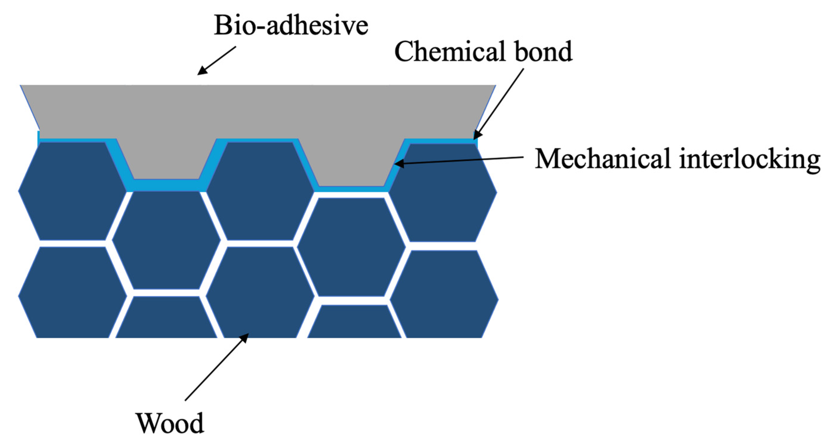
2.1. Bio-Adhesive
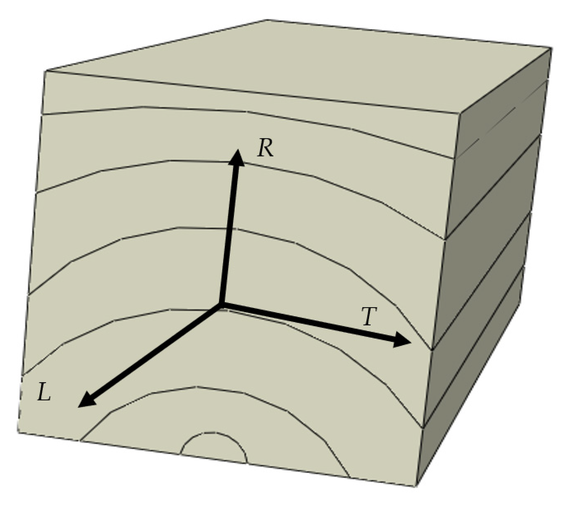
2.2. Substrate
2.3. Toughened Substrate
3. Experimental Procedure
3.1. Bulk Testing
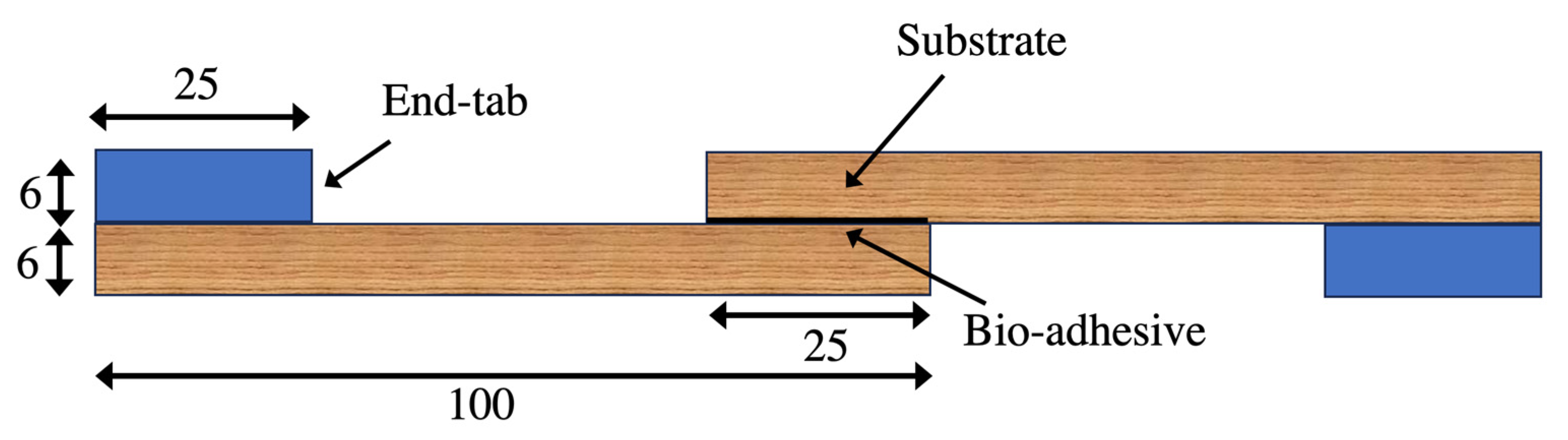
3.2. Joint Testing
Surface Preparation
3.3. Testing Condition
4. Experimental Results and Discussion
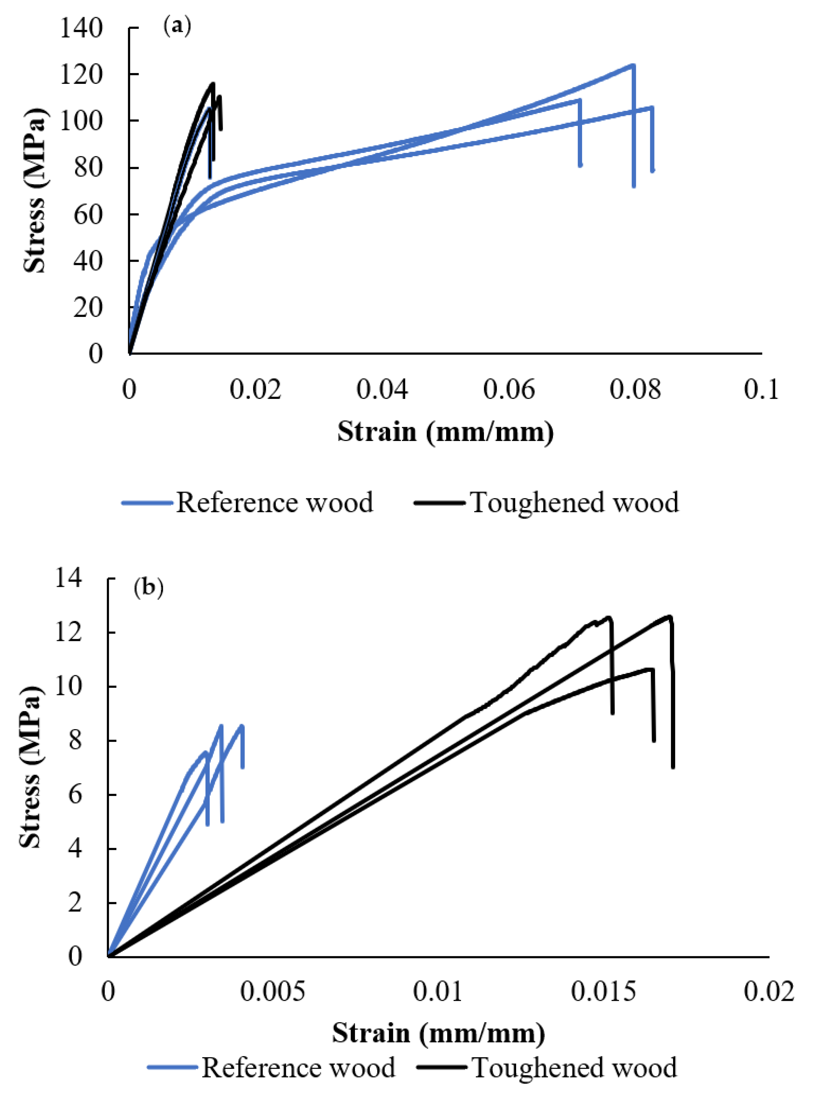
4.1. Bulk Testing
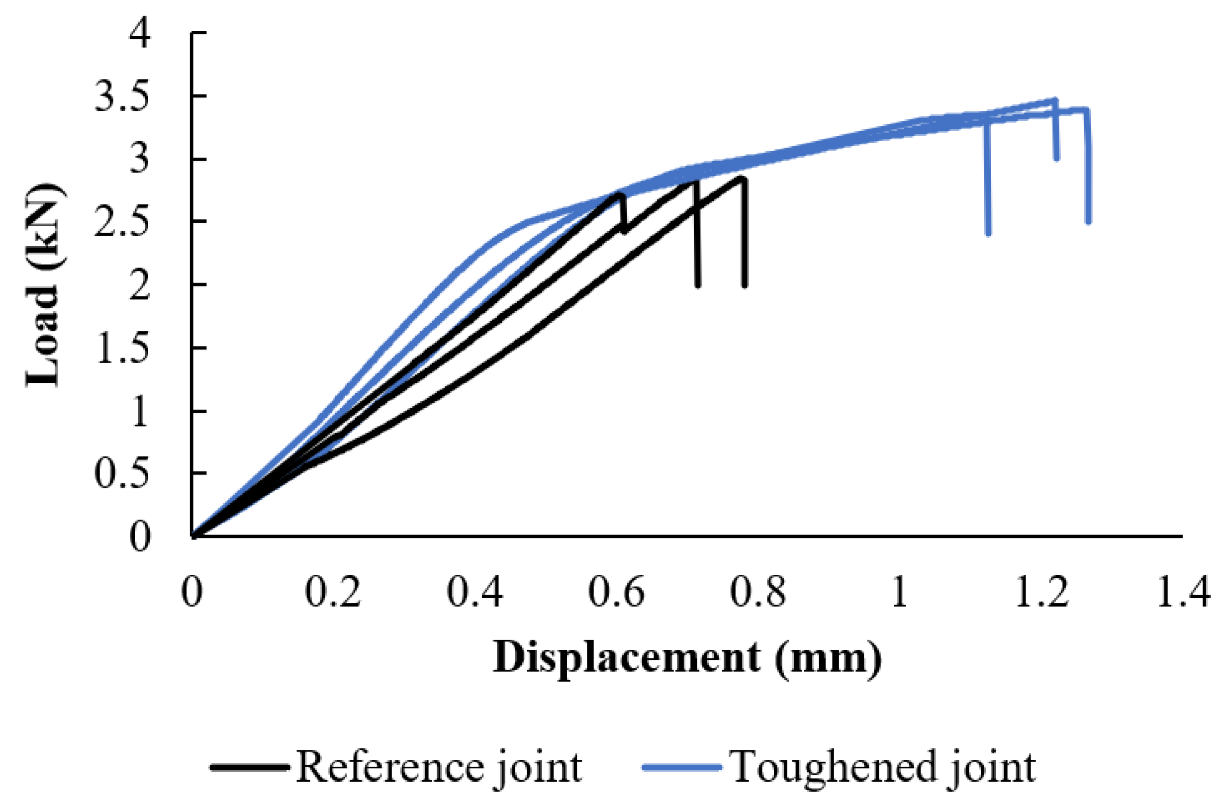
4.2. Joint Testing
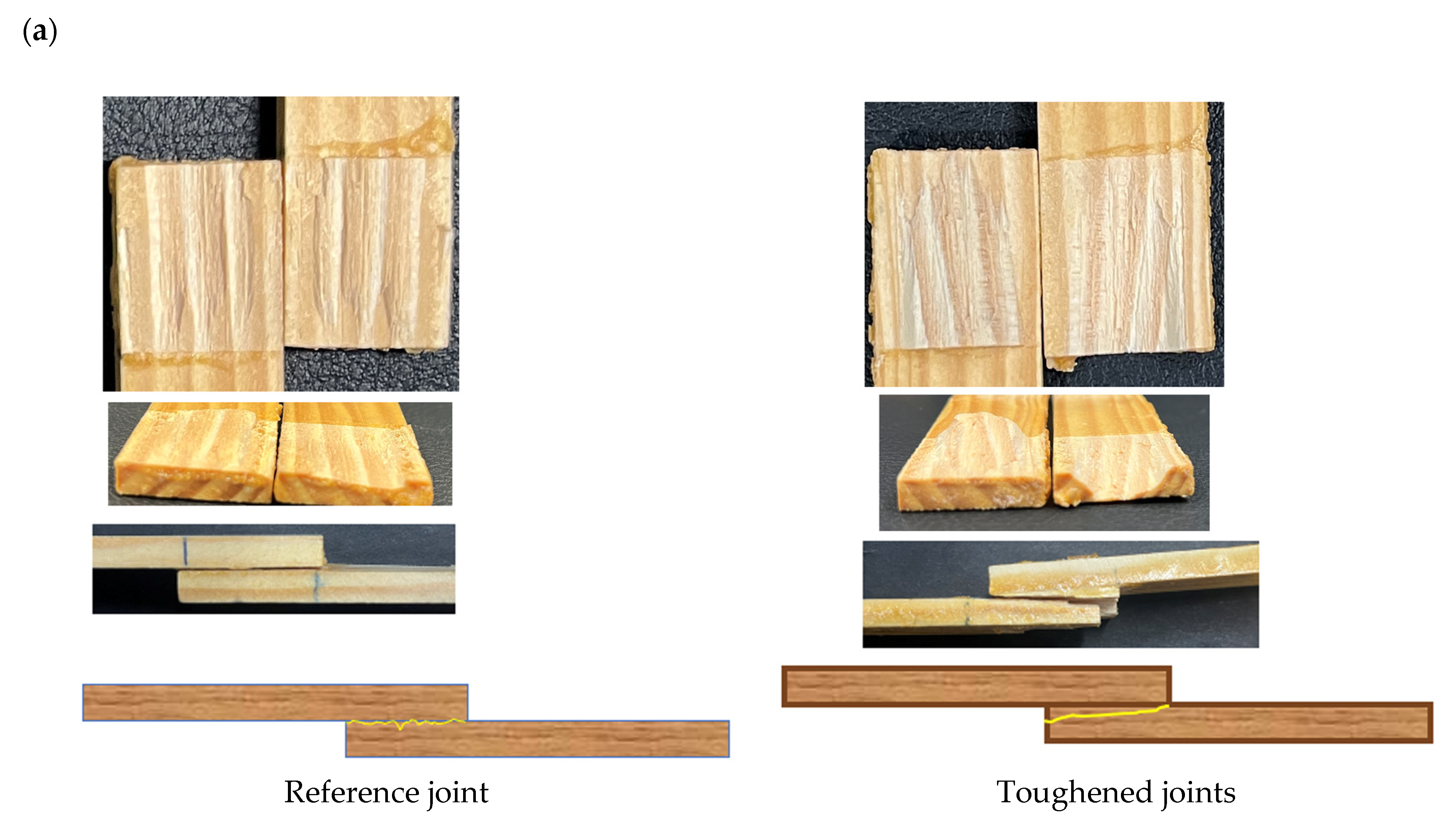
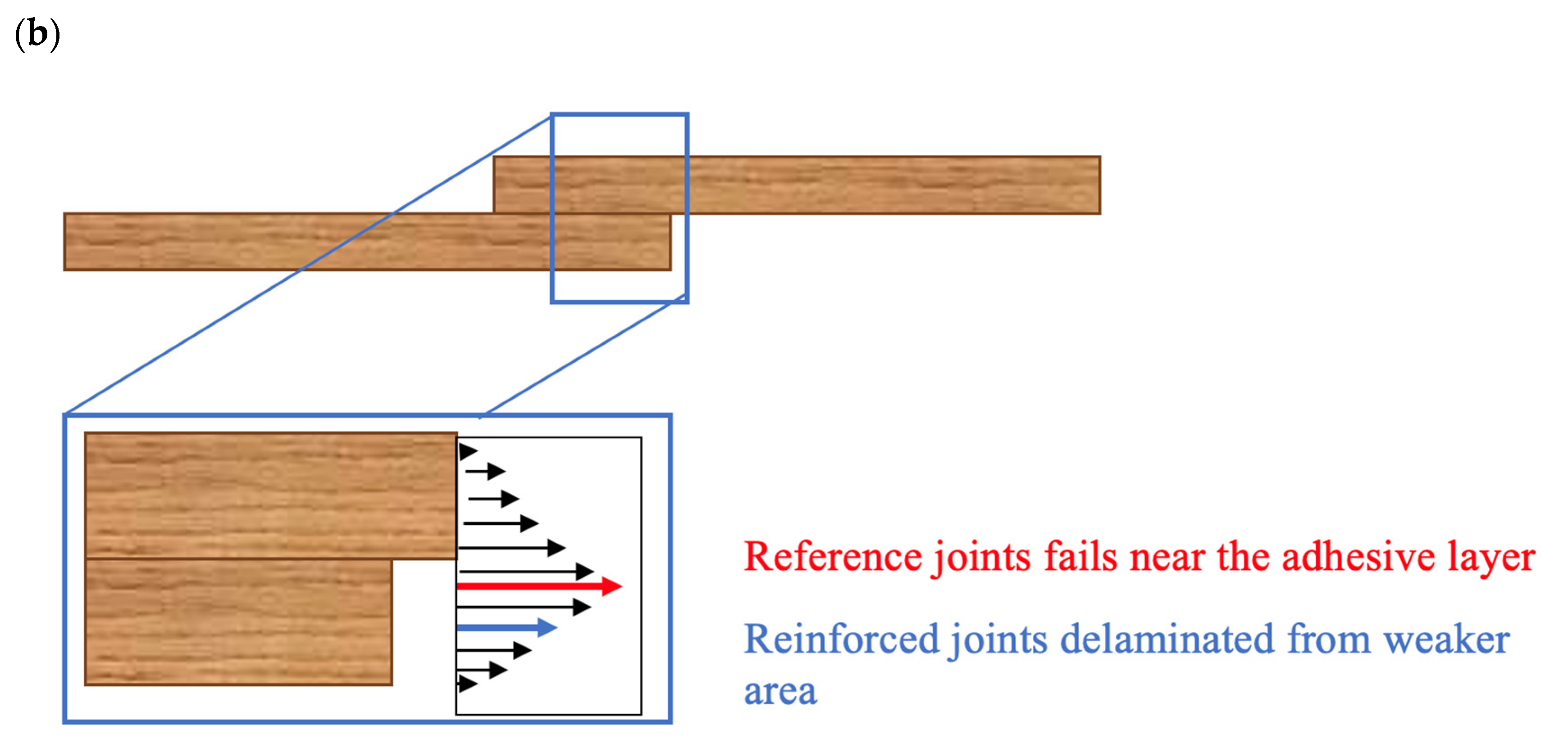
4.2.1. Fracture Surfaces
4.2.2. Scanning Electron Microscopy (SEM) Analysis
5. Numerical Analysis
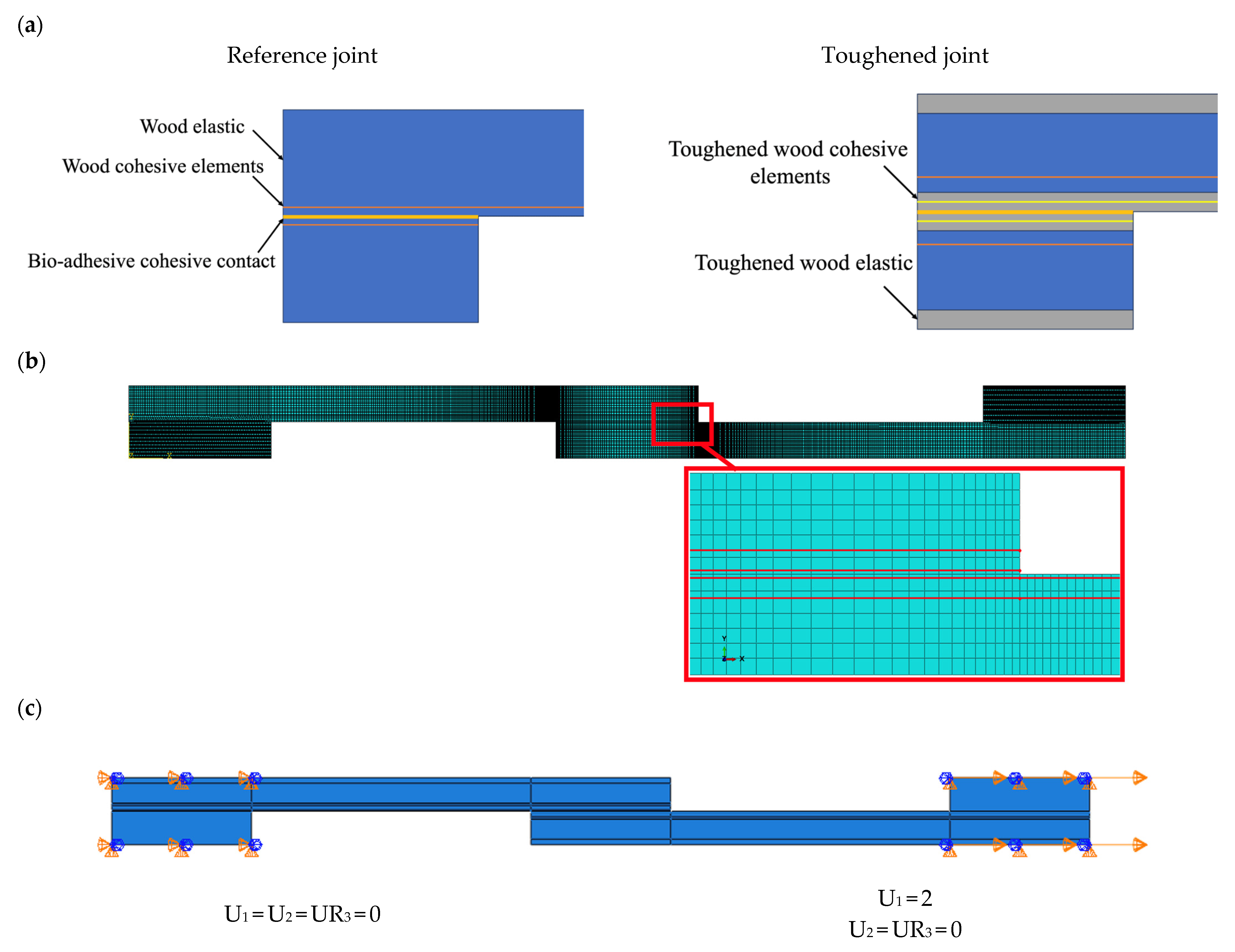
5.1. Numerical Details
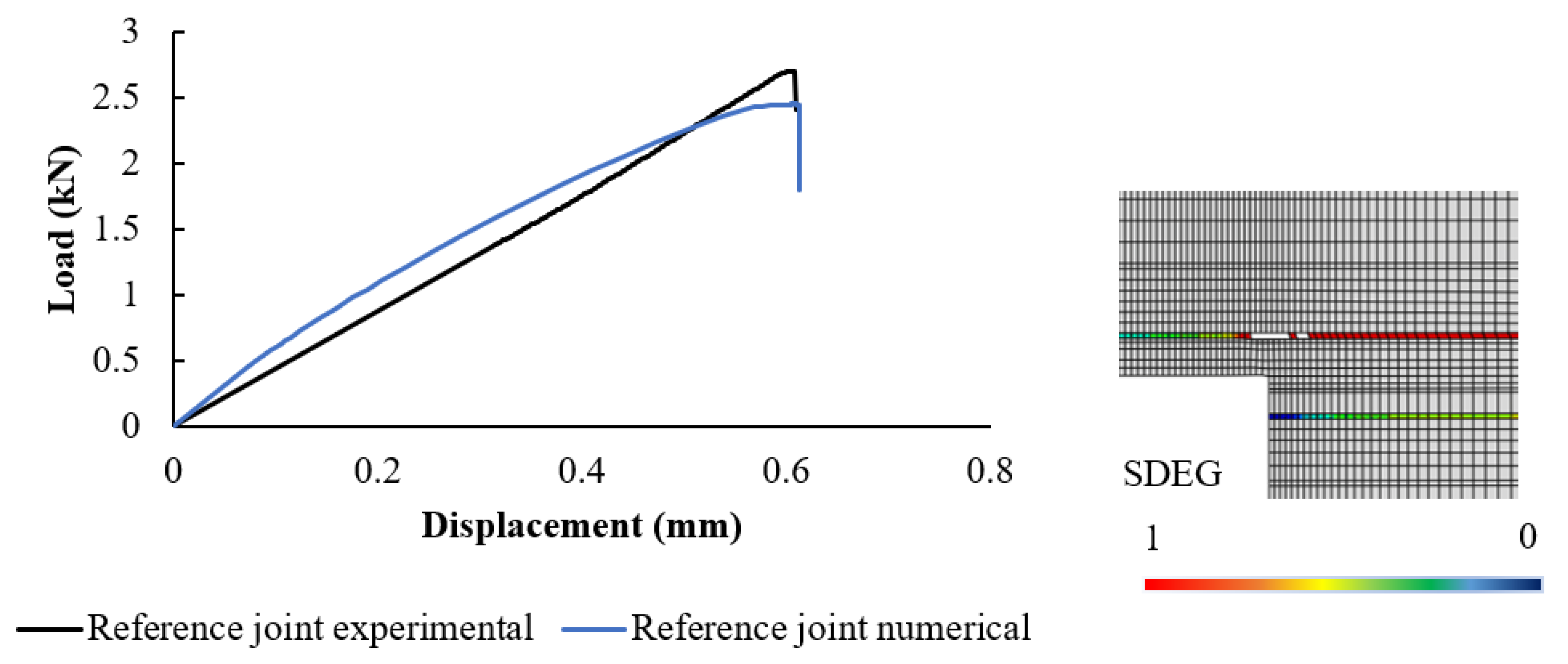
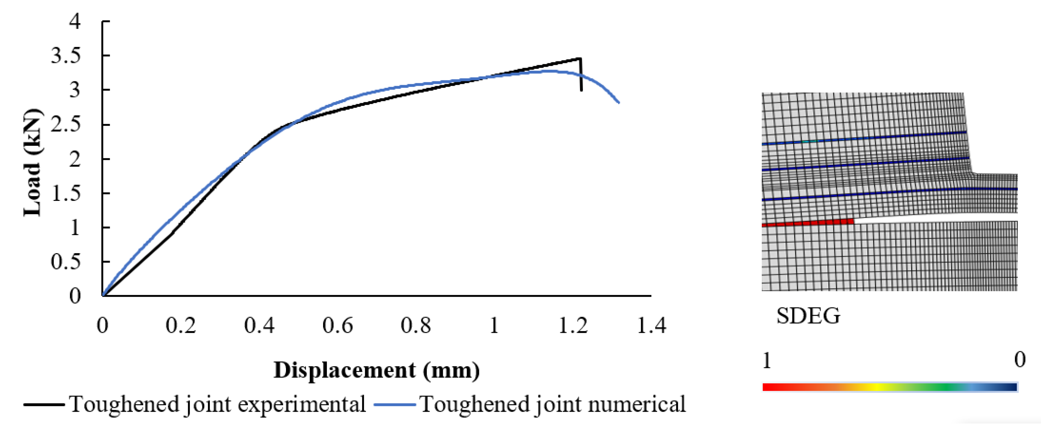
5.2. Numerical Results
6. Conclusions
- ▪
- The toughened substrates increased the delamination thickness and the joint strength by 85% compared to regular pine substrates.
- ▪
- The failure behavior, failure load, and absorbed energy of the joints were explored and supported by a finite element method model.
- ▪
- The model reduced the stress concentration at the overlap edges and increased the stress distribution over a wider area.
- ▪
- The study presented a practical technique for enhancing wooden joint performance using bio-adhesive infusion.
- ▪
- The study offered insights into the underlying mechanics of the observed improvements.
Author Contributions
Funding
Institutional Review Board Statement
Informed Consent Statement
Data Availability Statement
Conflicts of Interest
References
- Gajula, S.; Antonyraj, C.A.; Odaneth, A.A.; Srinivasan, K. A consolidated road map for economically gainful efficient utilization of agro-wastes for eco-friendly products. Biofuels Bioprod. Biorefining 2019, 13, 899–911. [Google Scholar] [CrossRef]
- Zhang, Y.; Duan, C.; Bokka, S.K.; He, Z.; Ni, Y. Molded fiber and pulp products as green and sustainable alternatives to plastics: A mini review. J. Bioresour. Bioprod. 2022, 7, 14–25. [Google Scholar] [CrossRef]
- Borges, C.S.P.; Jalali, S.; Tsokanas, P.; Marques, E.A.S.; Carbas, R.J.C.; da Silva, L.F.M. Sustainable Development Approaches through Wooden Adhesive Joints Design. Polymers 2022, 15, 89. [Google Scholar] [CrossRef] [PubMed]
- Hu, M.; Duan, Z.; Zhou, X.; Du, G.; Li, T. Effects of surface characteristics of wood on bonding performance of low-molar ratio urea–formaldehyde resin. J. Adhes. 2022, 99, 803–816. [Google Scholar] [CrossRef]
- Oliveira, P.R.; May, M.; Panzera, T.H.; Scarpa, F.; Hiermaier, S. Reinforced biobased adhesive for eco-friendly sandwich panels. Int. J. Adhes. Adhes. 2020, 98, 102550. [Google Scholar] [CrossRef]
- Bogue, R. Recent developments in adhesive technology: A review. Assem. Autom. 2011, 31, 207–211. [Google Scholar] [CrossRef]
- Gurr, J.; Barbu, M.C.; Frühwald, A.; Chaowana, P. The bond strength development of coconut wood in relation to its density variations. J. Adhes. 2022, 98, 1520–1533. [Google Scholar] [CrossRef]
- de Queiroz, H.F.M.; Banea, M.D.; Cavalcanti, D.K.K. Adhesively bonded joints of jute, glass and hybrid jute/glass fibre-reinforced polymer composites for automotive industry. Appl. Adhes. Sci. 2021, 9, 1–14. [Google Scholar] [CrossRef]
- Ammann, S.; Niemz, P. Specific fracture energy at glue joints in European beech wood. Int. J. Adhes. Adhes. 2015, 60, 47–53. [Google Scholar] [CrossRef]
- Tserpes, K.; Barroso-Caro, A.; Carraro, P.A.; Beber, V.C.; Floros, I.; Gamon, W.; Kozłowski, M.; Santandrea, F.; Shahverdi, M.; Skejić, D.; et al. A review on failure theories and simulation models for adhesive joints. J. Adhes. 2021, 98, 1855–1915. [Google Scholar] [CrossRef]
- Gooch, J.W. ASTM D638. In Encyclopedic Dictionary of Polymers; Springer: New York, NY, USA, 2011; p. 51. [Google Scholar]
- Faidzi, M.K.; Abdullah, S.; Abdullah, M.F.; Singh, S.S.K.; Azman, A.H. Evaluating an adhesive effect on core surface configuration for sandwich panel with peel simulation approach. J. Mech. Sci. Technol. 2021, 35, 2431–2439. [Google Scholar] [CrossRef]
- Santoni, I.; Pizzo, B. Evaluation of alternative vegetable proteins as wood adhesives. Ind. Crop. Prod. 2013, 45, 148–154. [Google Scholar] [CrossRef]
- Shang, X.; Marques, E.; Machado, J.; Carbas, R.; Jiang, D.; da Silva, L. A strategy to reduce delamination of adhesive joints with composite substrates. Proc. Inst. Mech. Eng. Part L J. Mater. Des. Appl. 2018, 233, 521–530. [Google Scholar] [CrossRef]
- Wiktor, W.; Pała, T. Selected aspects of cohesive zone modeling in fracture mechanics. Metals 2021, 11, 302. [Google Scholar]
- Baumberger, S.; Lapierre, C.; Monties, B.; Della Valle, G. Use of kraft lignin as filler for starch films. Polym. Degrad. Stab. 1998, 59, 273–277. [Google Scholar] [CrossRef]
- Azari, S.; Papini, M.; Spelt, J.K. Effect of Surface Roughness on the Performance of Adhesive Joints Under Static and Cyclic Loading. J. Adhes. 2010, 86, 742–764. [Google Scholar] [CrossRef]
- Rangaswamy, H.; Sogalad, I.; Basavarajappa, S.; Acharya, S.; Patel, G.C.M. Experimental analysis and prediction of strength of adhesive-bonded single-lap composite joints: Taguchi and artificial neural network approaches. SN Appl. Sci. 2020, 2, 1–15. [Google Scholar] [CrossRef]
- Stucki, S.; Lange, H.; Dreimol, C.H.; Weinand, Y.; Burgert, I. The influence of wood surface treatments with different biomolecules on dry and wet strength of linear friction welded joints. J. Adhes. Sci. Technol. 2023, 37, 1–20. [Google Scholar] [CrossRef]
- ASTM D6866-22; Standard Test Methods for Determining the Biobased Content of Solid, Liquid, and Gaseous Samples Using Radiocarbon Analysis. ASTM: West Conshohocken, PA, USA, 2022.
- Jalali, S.; Borges, C.d.S.P.; Carbas, R.J.C.; Marques, E.A.d.S.; Bordado, J.C.M.; da Silva, L.F.M. Characterization of Densified Pine Wood and a Zero-Thickness Bio-Based Adhesive for Eco-Friendly Structural Applications. Materials 2023, 16, 7147. [Google Scholar] [CrossRef]
- Oliveira, J.; Demoura, M.; Silva, M.; Morais, J. Numerical analysis of the MMB test for mixed-mode I/II wood fracture. Compos. Sci. Technol. 2007, 67, 1764–1771. [Google Scholar] [CrossRef]
- Gültekin, K.; Akpinar, S.; Özel, A. The effect of the adherend width on the strength of adhesively bonded single-lap joint: Experimental and numerical analysis. Compos. Part B Eng. 2014, 60, 736–745. [Google Scholar] [CrossRef]
- Pisharody, A.P.; Blandford, B.; Smith, D.E.; Jack, D.A. An experimental investigation on the effect of adhesive distribution on strength of bonded joints. Appl. Adhes. Sci. 2019, 7, 1–12. [Google Scholar] [CrossRef]


| Young’s Modulus (MPa) | Tensile Strength (MPa) | Mode I Fracture Energy (N/mm) | Mode II Fracture Energy (N/mm) |
|---|---|---|---|
| 197.09 ± 9.76 | 3.27 ± 0.14 | 0.33 ± 0.03 | 1.27 ± 0.1 |
| EL (GPa) | ER (GPa) | ET (GPa) | νLT | νLR | νTR | GLR (GPa) | GLT (GPa) | GTR (GPa) |
|---|---|---|---|---|---|---|---|---|
| 12.0 | 1.9 | 1.0 | 0.5 | 0.4 | 0.3 | 1.1 | 1.0 | 0.3 |
| Young’s Modulus (MPa) | Tensile Strength (MPa) | Strain at Failure (%) | ||
|---|---|---|---|---|
| Fiber direction | Reference | 12.3 ± 1.2 | 93.2 ± 4.2 | 7.6 ± 0.3 |
| Toughened | 11.9 ± 1.8 | 102.3 ± 8.2 | 1.3 ± 0.1 | |
| Matrix direction | Reference | 2.1 ± 0.1 | 8.1 ± 0.3 | 0.4 ± 0.1 |
| Toughened | 0.8 ± 0.1 | 11.8 ± 0.8 | 1.6 ± 0.1 | |
| (MPa) | (MPa) | (MPa) | (MPa) | (MPa) | (MPa) |
|---|---|---|---|---|---|
| 97.5 | 7.9 | 4.2 | 16.0 | 16.0 | 4.5 |
Disclaimer/Publisher’s Note: The statements, opinions and data contained in all publications are solely those of the individual author(s) and contributor(s) and not of MDPI and/or the editor(s). MDPI and/or the editor(s) disclaim responsibility for any injury to people or property resulting from any ideas, methods, instructions or products referred to in the content. |
© 2024 by the authors. Licensee MDPI, Basel, Switzerland. This article is an open access article distributed under the terms and conditions of the Creative Commons Attribution (CC BY) license (https://creativecommons.org/licenses/by/4.0/).
Share and Cite
Jalali, S.; Borges, C.d.S.P.; Carbas, R.J.C.; Marques, E.A.d.S.; Akhavan-Safar, A.; Barbosa, A.S.O.F.; Bordado, J.C.M.; da Silva, L.F.M. A Novel Technique for Substrate Toughening in Wood Single Lap Joints Using a Zero-Thickness Bio-Adhesive. Materials 2024, 17, 448. https://doi.org/10.3390/ma17020448
Jalali S, Borges CdSP, Carbas RJC, Marques EAdS, Akhavan-Safar A, Barbosa ASOF, Bordado JCM, da Silva LFM. A Novel Technique for Substrate Toughening in Wood Single Lap Joints Using a Zero-Thickness Bio-Adhesive. Materials. 2024; 17(2):448. https://doi.org/10.3390/ma17020448
Chicago/Turabian StyleJalali, Shahin, Catarina da Silva Pereira Borges, Ricardo João Camilo Carbas, Eduardo André de Sousa Marques, Alireza Akhavan-Safar, Ana Sofia Oliveira Ferreira Barbosa, João Carlos Moura Bordado, and Lucas Filipe Martins da Silva. 2024. "A Novel Technique for Substrate Toughening in Wood Single Lap Joints Using a Zero-Thickness Bio-Adhesive" Materials 17, no. 2: 448. https://doi.org/10.3390/ma17020448
APA StyleJalali, S., Borges, C. d. S. P., Carbas, R. J. C., Marques, E. A. d. S., Akhavan-Safar, A., Barbosa, A. S. O. F., Bordado, J. C. M., & da Silva, L. F. M. (2024). A Novel Technique for Substrate Toughening in Wood Single Lap Joints Using a Zero-Thickness Bio-Adhesive. Materials, 17(2), 448. https://doi.org/10.3390/ma17020448