
A Method for Straightening Distorted Giga-Cast Large Thin-Walled Components


Abstract
1. Introduction
2. Distortion Straightening Method
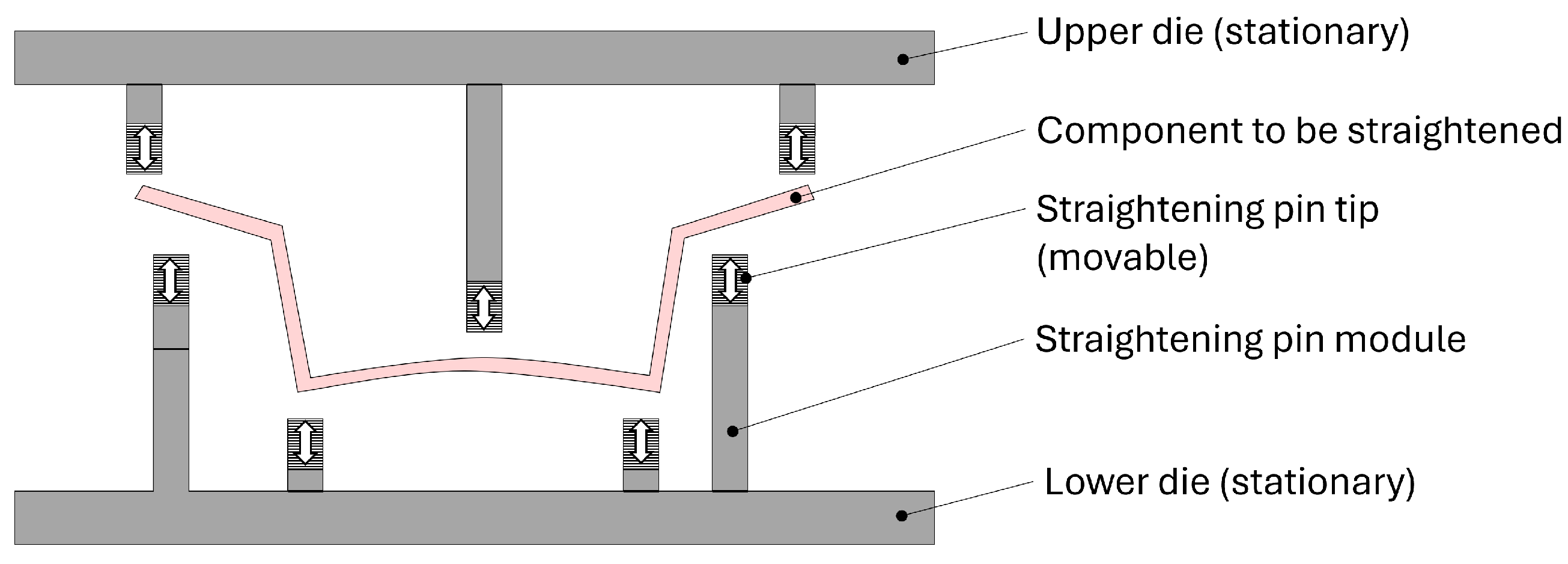
2.1. Straightening Machine Concept and Straightening Process
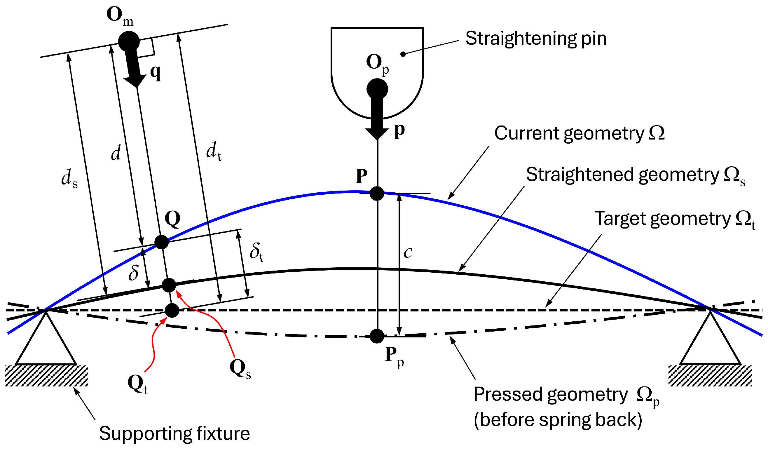
2.2. Quantification of Distortion
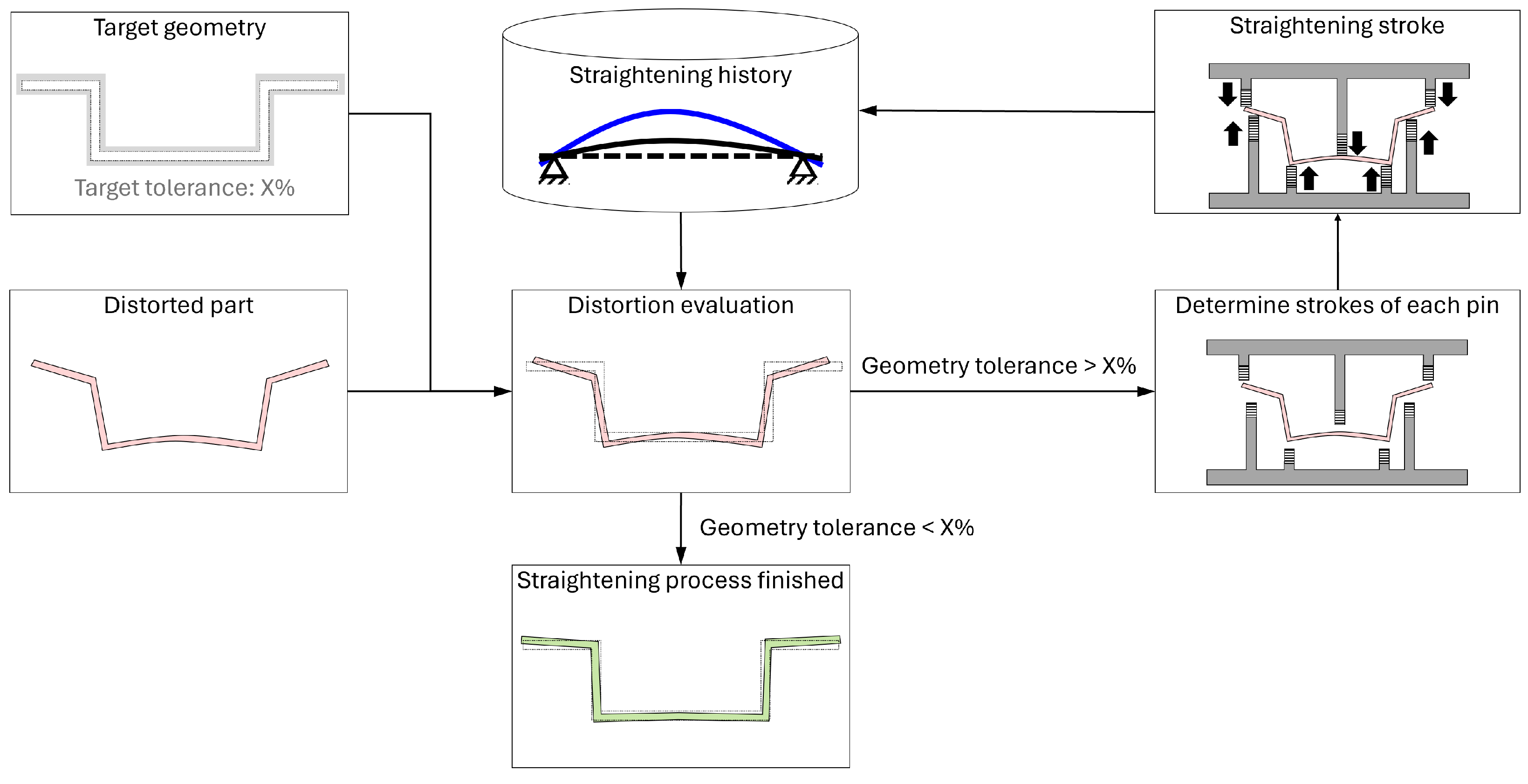
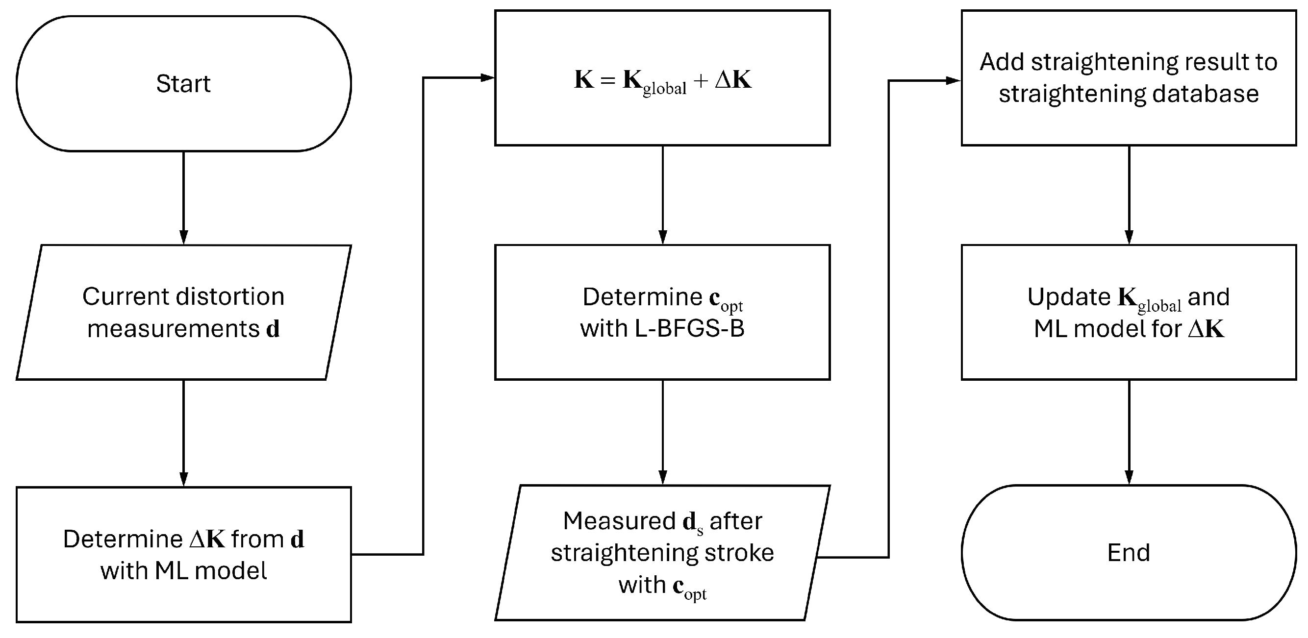
2.3. Straightening Stroke Decision Algorithm
3. Numerical Experiments
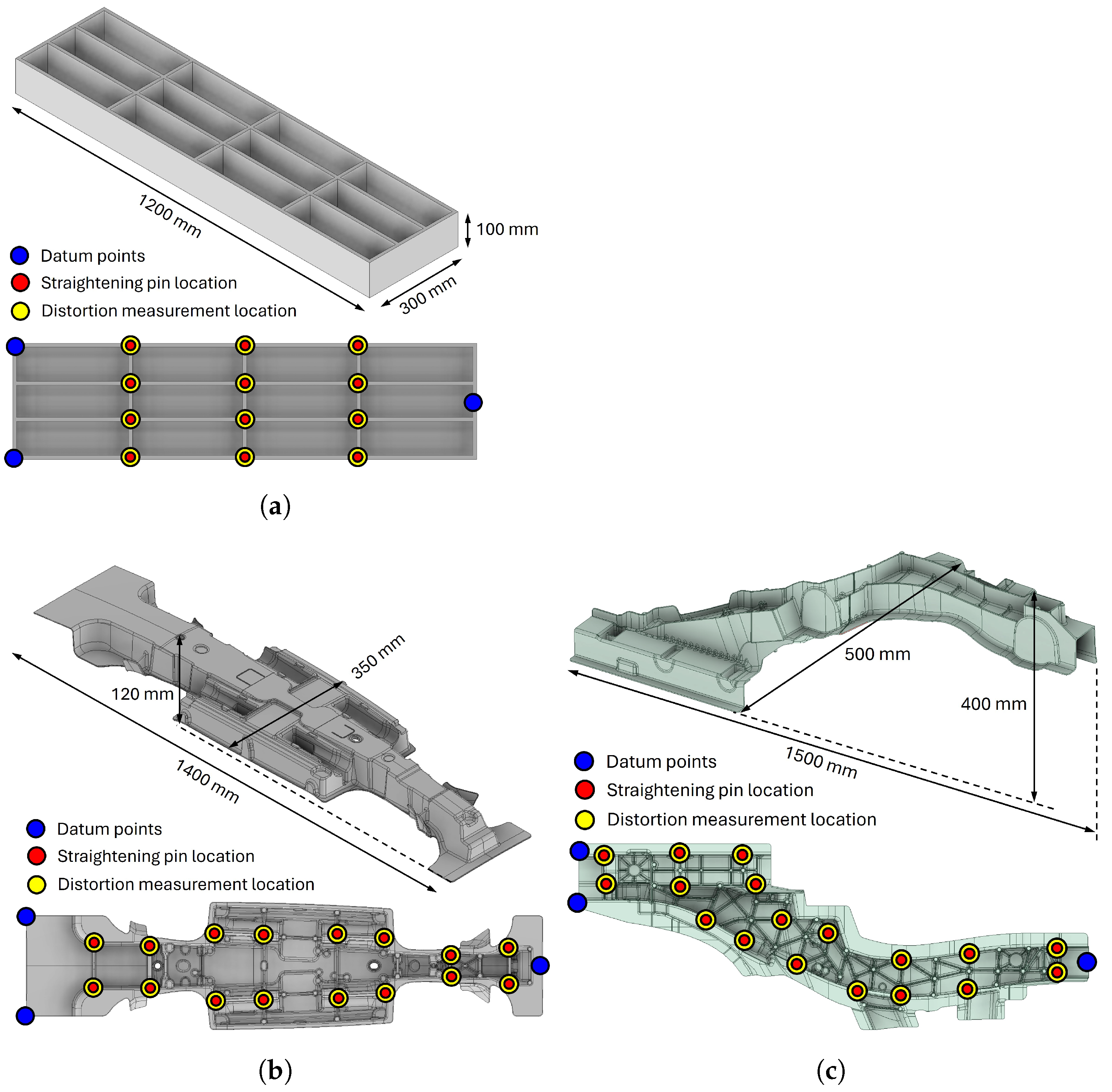
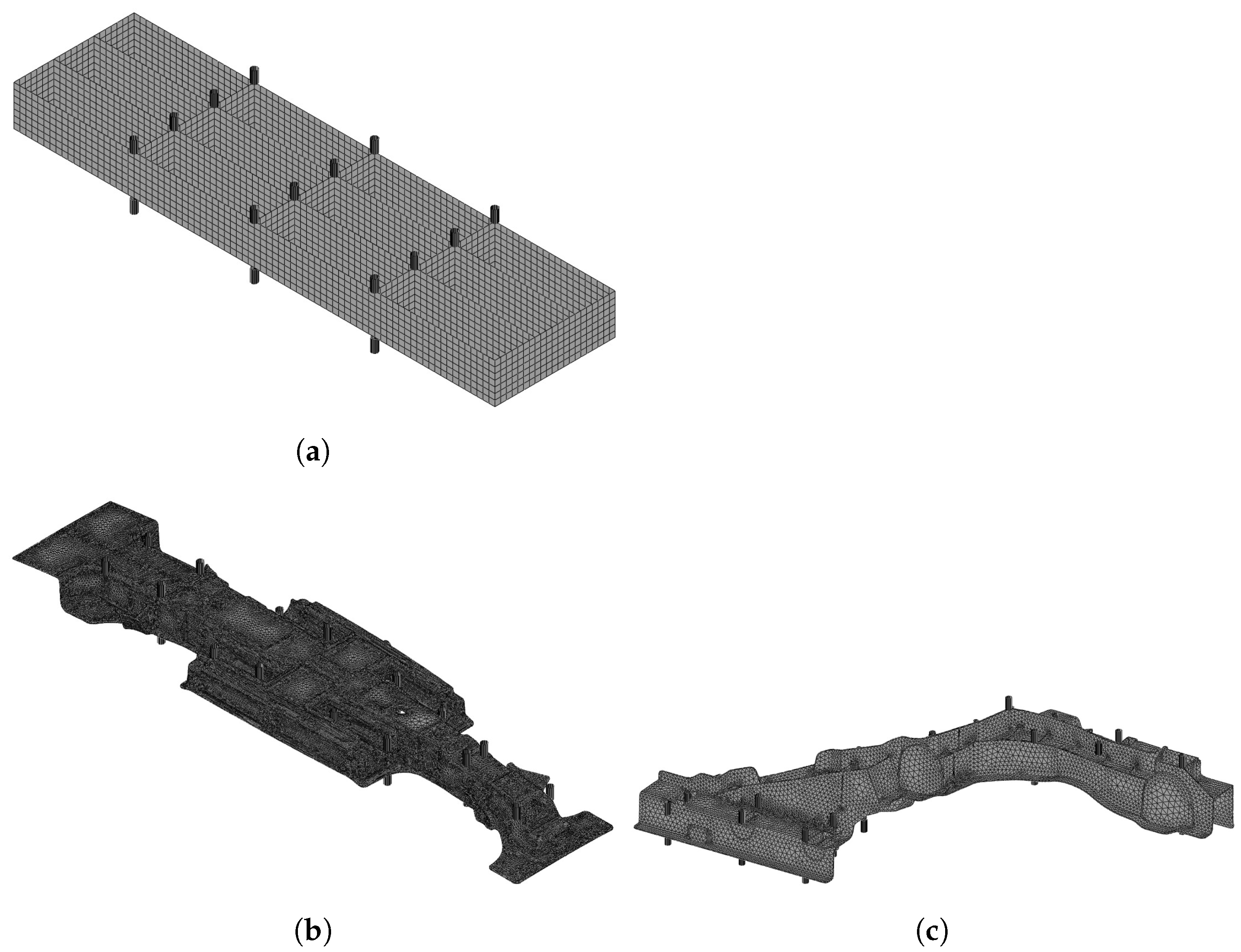
3.1. Target Components, Straightening Pins, and Distortion Measurement Locations
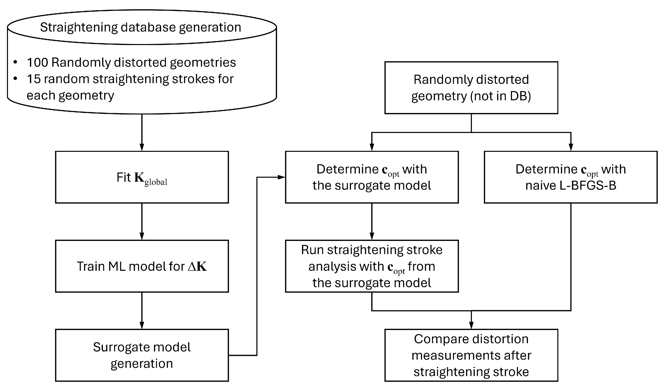
3.2. Numerical Experiment Procedure
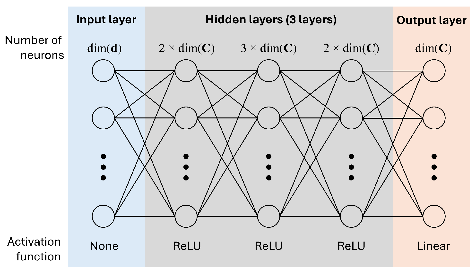
3.3. Machine Learning Models for
4. Results and Discussion
5. Conclusions
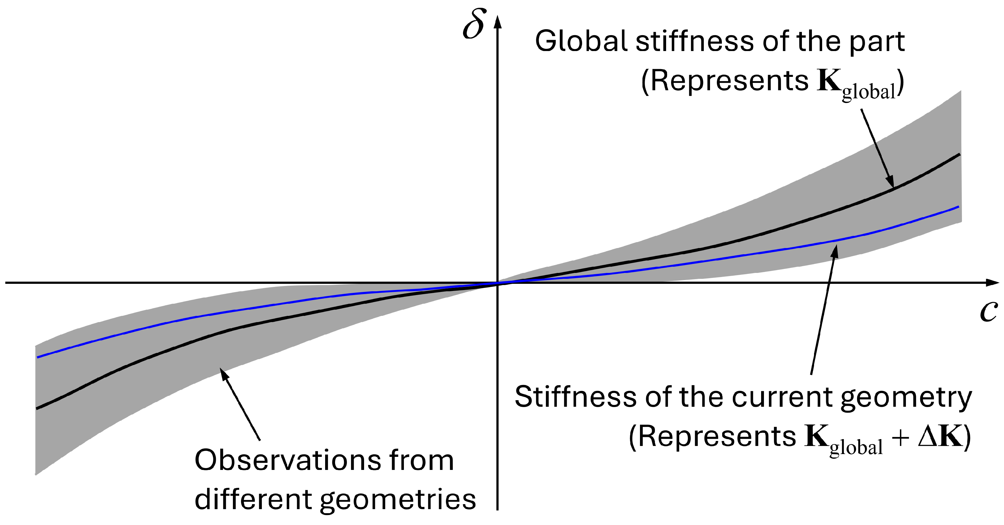
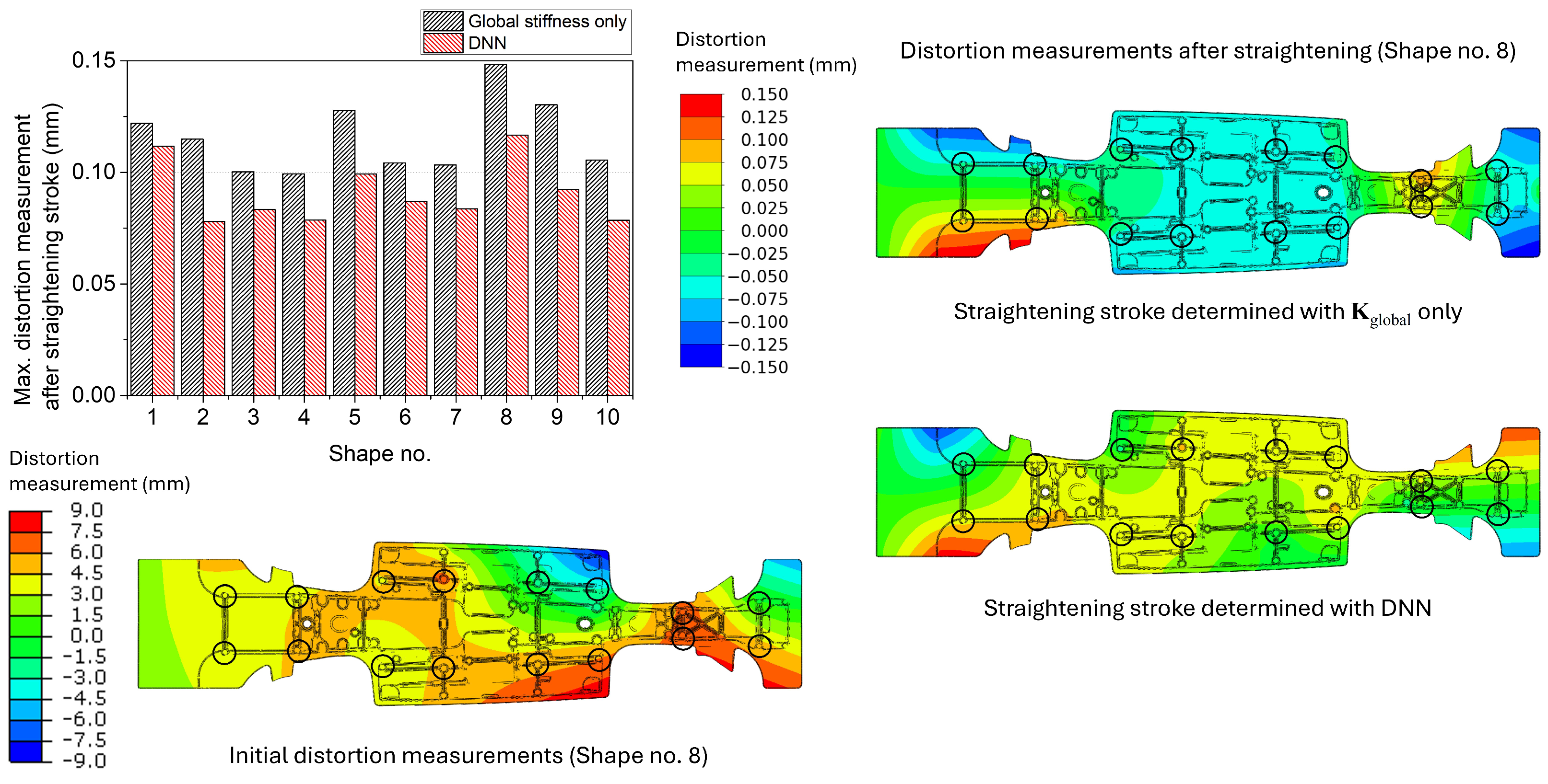
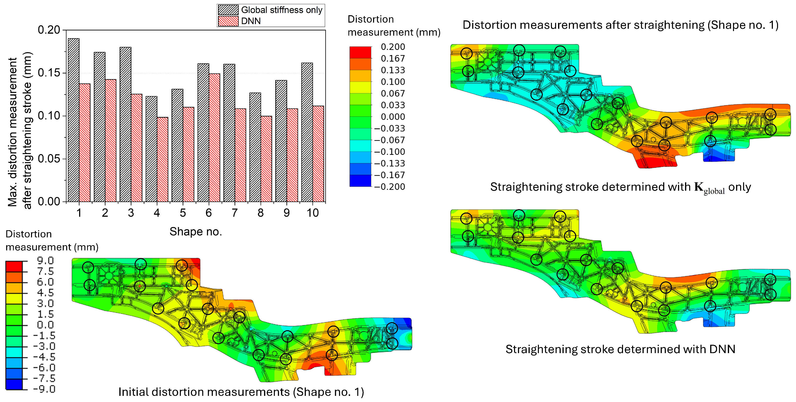
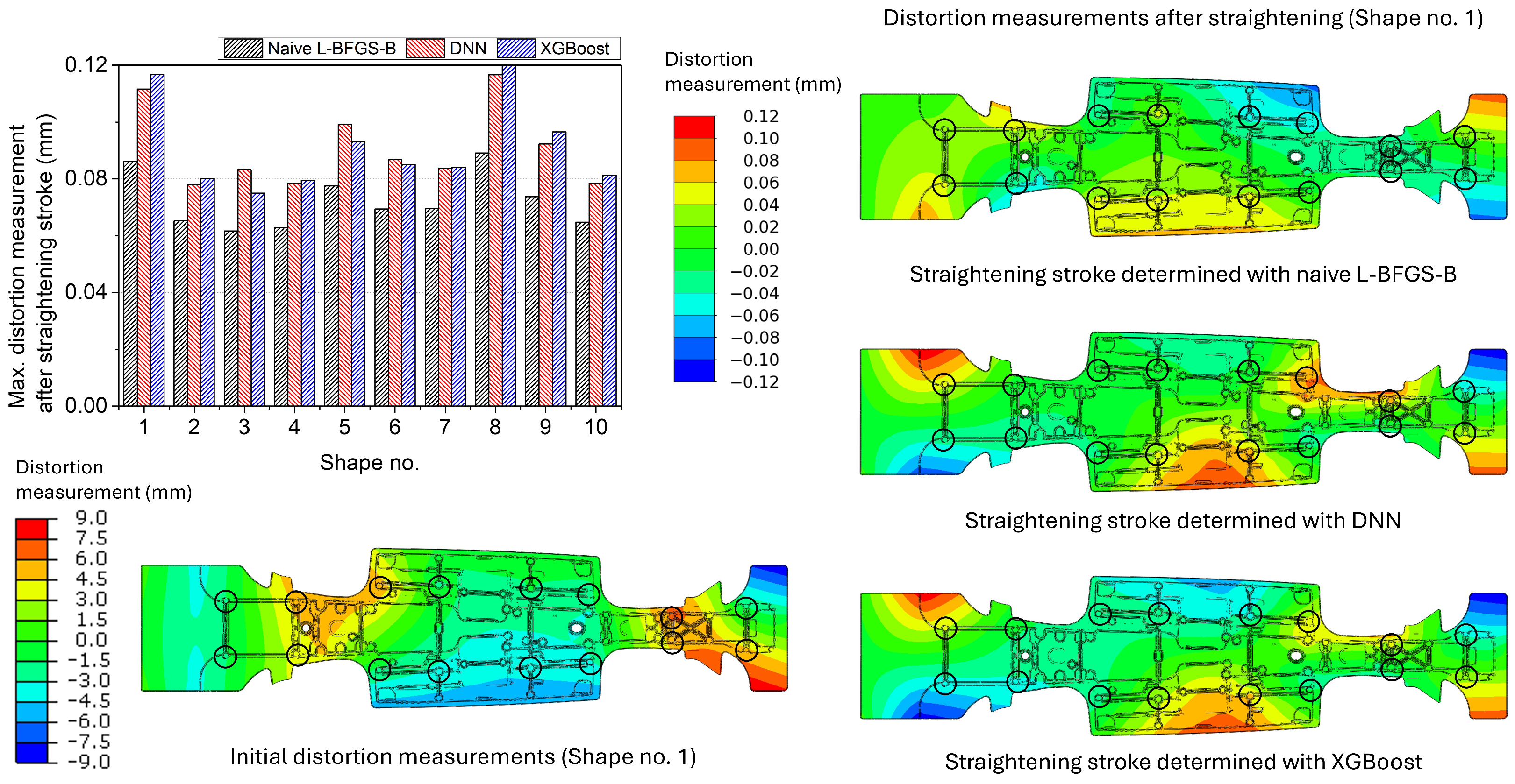
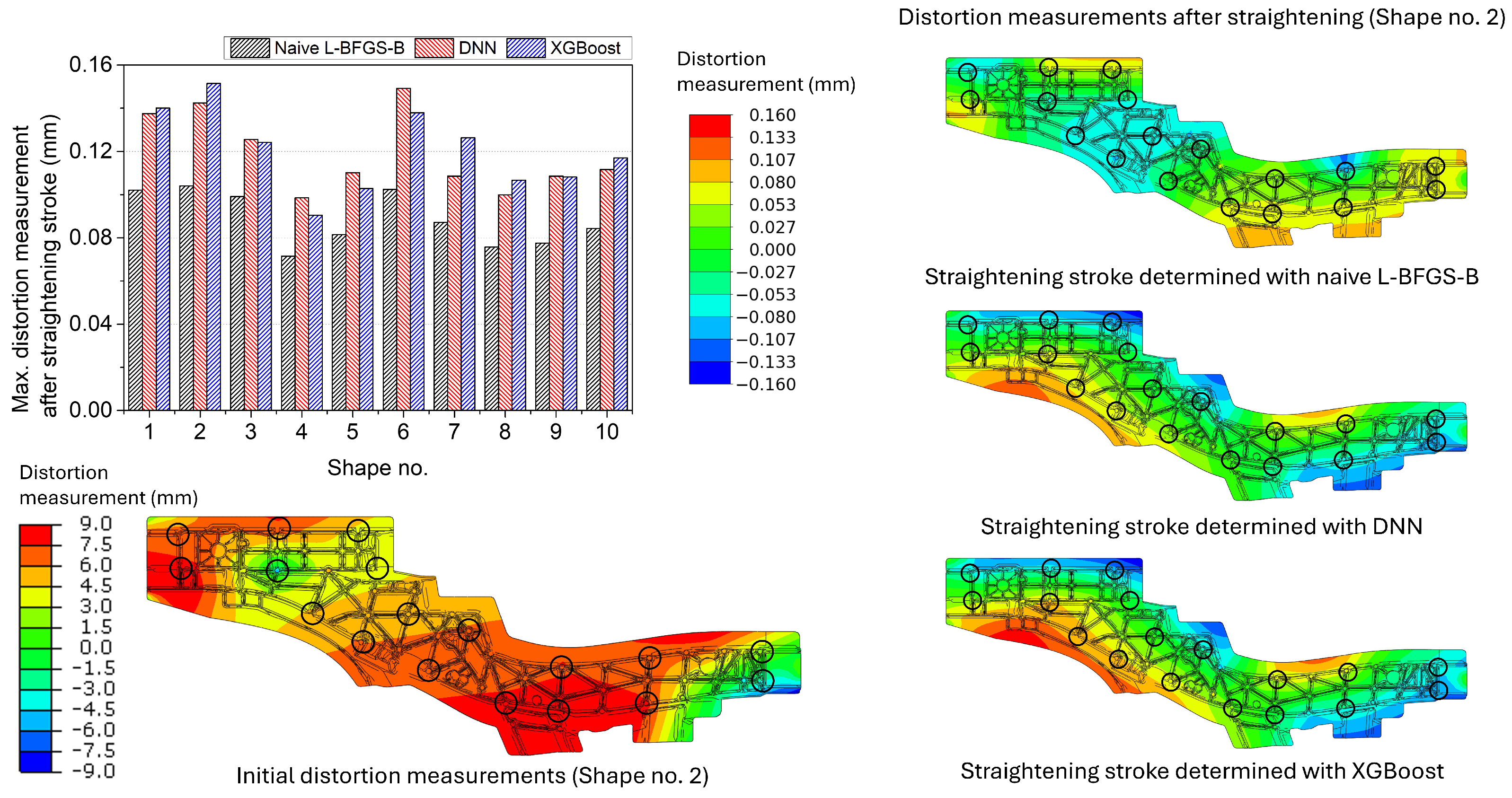
- The effect of the current geometry should be considered when deciding the straightening stroke to make the straightening strokes effective. The global stiffness matrix can be used alone for straightening, but the determined straightening strokes might be less effective.
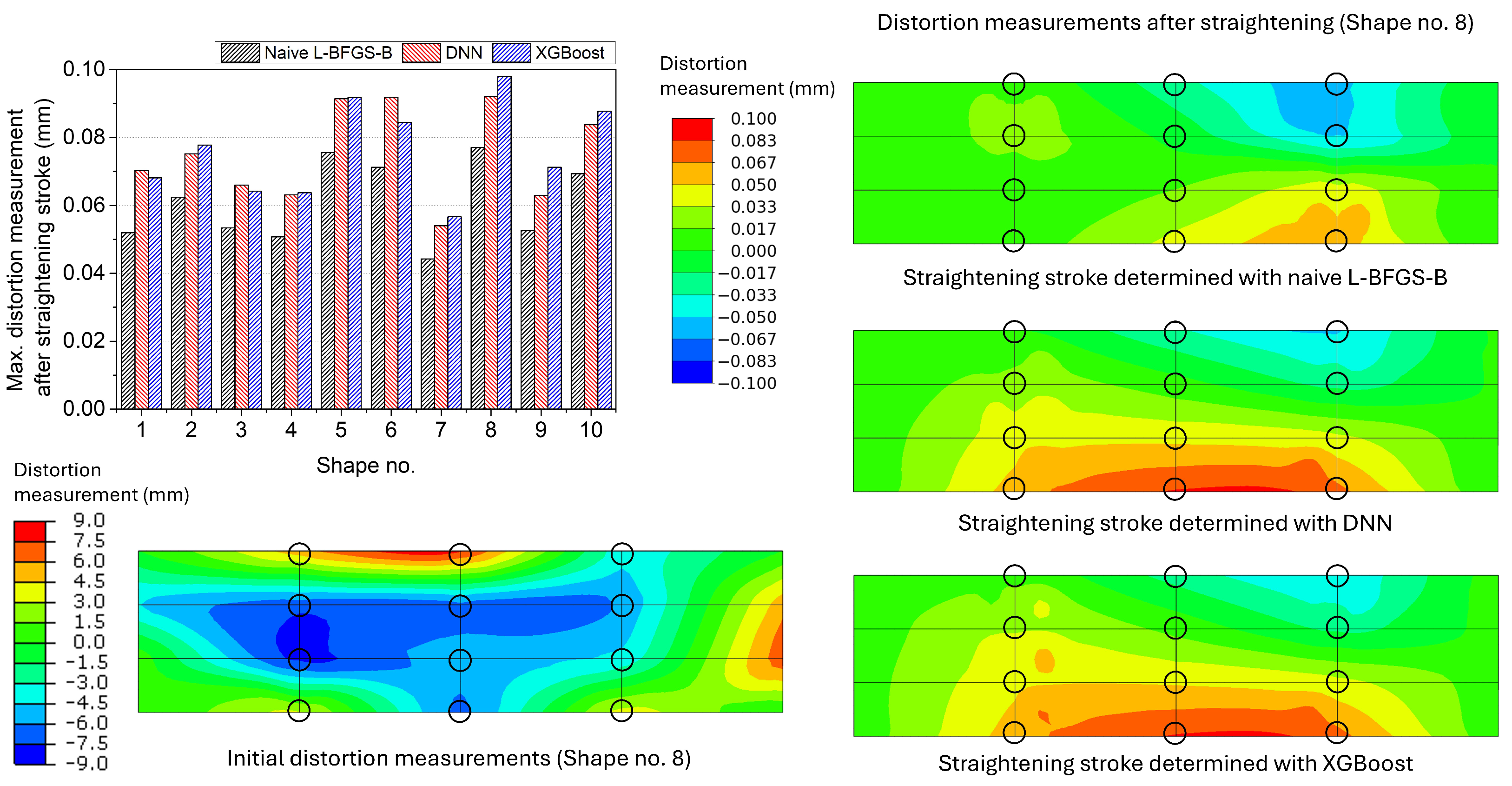
- The proposed DNN and XGBoost models adequately modelled the stiffness change due to the current geometry. Their performances on the straightening stroke decision were similar; meanwhile, the DNN model showed slightly better performance.
- Regarding the straightening results from the naive L-BFGS-B as the optimum, the maximum distortion measurements after the straightening strokes decided from the surrogate models differed by 28.7% on average. The surrogate models could provide admissible straightening stroke results, considering that the naive L-BFGS-B process is computationally expensive, which means that it is not appropriate to operate the straightening process.
- The surrogate models decided the straightening strokes so that the maximum remaining distortion became 0.02% of the largest dimension of each target geometry for all target components. The suggested straightening method and algorithm were suitable for straightening distorted large thin-walled components.
Author Contributions
Funding
Institutional Review Board Statement
Informed Consent Statement
Data Availability Statement
Conflicts of Interest
Appendix A. Tables for Maximum Distortion Measurements after the Straightening Stroke

| Unit: mm | ||||
|---|---|---|---|---|
| Shape No. | Naive L-BFGS-B | Only | DNN | XGBoost |
| 1 | ||||
| 2 | ||||
| 3 | ||||
| 4 | ||||
| 5 | ||||
| 6 | ||||
| 7 | ||||
| 8 | ||||
| 9 | ||||
| 10 | ||||
| Unit: mm | ||||
|---|---|---|---|---|
| Shape No. | Naive L-BFGS-B | Only | DNN | XGBoost |
| 1 | ||||
| 2 | ||||
| 3 | ||||
| 4 | ||||
| 5 | ||||
| 6 | ||||
| 7 | ||||
| 8 | ||||
| 9 | ||||
| 10 | ||||
| Unit: mm | ||||
|---|---|---|---|---|
| Shape No. | Naive L-BFGS-B | Only | DNN | XGBoost |
| 1 | ||||
| 2 | ||||
| 3 | ||||
| 4 | ||||
| 5 | ||||
| 6 | ||||
| 7 | ||||
| 8 | ||||
| 9 | ||||
| 10 | ||||
References
- Baser, T.A.; Umay, E.; Akıncı, V. New Trends in Aluminum Die Casting Alloys for Automotive Applications. Eurasia Proc. Sci. Technol. Eng. Math. 2022, 21, 79–87. [Google Scholar] [CrossRef]
- Lehmhus, D. Advances in Metal Casting Technology: A Review of State of the Art, Challenges and Trends—Part I: Changing Markets, Changing Products. Metals 2022, 12, 1959. [Google Scholar] [CrossRef]
- Triller, J.; Lopez, M.L.; Nossek, M.; Frenzel, M.A. Multidisciplinary optimization of automotive mega-castings merging classical structural optimization with response-surface-based optimization enhanced by machine learning. Sci. Rep. 2023, 13, 21678. [Google Scholar] [CrossRef] [PubMed]
- Xu, Y.; Zhang, Y.; Li, J.; Wang, P.; Wang, J.; Chen, H.; Sun, H.; Zhan, H. Effects of Cr-addition on ageing response of an Al–Si–Mg die cast alloy. Mater. Sci. Eng. A 2024, 892, 146058. [Google Scholar] [CrossRef]
- Li, T.; Song, J.; Zhang, A.; You, G.; Yang, Y.; Jiang, B.; Qin, X.; Xu, C.; Pan, F. Progress and prospects in Mg-alloy super-sized high pressure die casting for automotive structural components. J. Magnes. Alloy. 2023, 11, 4166–4180. [Google Scholar] [CrossRef]
- Li, Z.; Tan, H.; Jarfors, A.E.; Jansson, P.; Lattanzi, L. Smart-Cast: An AI-Based System for Semisolid Casting Process Control. Procedia Comput. Sci. 2024, 232, 2440–2447. [Google Scholar] [CrossRef]
- Timelli, G.; Lohne, O.; Arnberg, L.; Laukli, H.I. Effect of solution heat treatments on the microstructure and mechanical properties of a die-cast AlSi7MgMn alloy. Metall. Mater. Trans. A 2008, 39, 1747–1758. [Google Scholar] [CrossRef]
- Anglada, E.; Meléndez, A.; Vicario, I.; Idoiaga, J.K.; Mugarza, A.; Arratibel, E. Prediction and validation of shape distortions in the simulation of high pressure die casting. J. Manuf. Process. 2018, 33, 228–237. [Google Scholar] [CrossRef]
- Hofer, P.; Kaschnitz, E.; Schumacher, P. Distortion and residual stress in high-pressure die castings: Simulation and measurements. Jom 2014, 66, 1638–1646. [Google Scholar] [CrossRef]
- Couto, C.P.; Revilla, R.I.; Politano, R.; Costa, I.; Panossian, Z.; De Graeve, I.; Rossi, J.L.; Terryn, H. Influence of austenitisation temperatures during hot stamping on the local electrochemical behaviour of 22MnB5 steel coated with hot-dip Al-Si. Corros. Sci. 2021, 190, 109673. [Google Scholar] [CrossRef]
- Khan, H.A.; Butt, S.U.; Baqai, A.A.; Saeed, H.A. A new approach to predict the flexibility and precision of manufacturing systems using geometric constraints and small displacement torsors. Procedia Manuf. 2018, 17, 294–301. [Google Scholar] [CrossRef]
- Guan, Q. 9—Control of buckling distortions in plates and shells. In Processes and Mechanisms of Welding Residual Stress and Distortion; Feng, Z., Ed.; Woodhead Publishing Series in Welding and Other Joining Technologies; Woodhead Publishing: Sawston, UK, 2005; pp. 295–343. [Google Scholar] [CrossRef]
- Hartlieb, A.; Hartlieb, M. The Impact of Giga-Castings on Car Manufacturing and Aluminum Content. Light Met. Age 2023, 3, 18–23. [Google Scholar]
- Cross, E.J.; Gibson, S.J.; Jones, M.R.; Pitchforth, D.J.; Zhang, S.; Rogers, T.J. Physics-Informed Machine Learning for Structural Health Monitoring. In Structural Health Monitoring Based on Data Science Techniques; Cury, A., Ribeiro, D., Ubertini, F., Todd, M.D., Eds.; Springer International Publishing: Cham, Switzerland, 2022; pp. 347–367. [Google Scholar] [CrossRef]
- Stoll, A.; Benner, P. Machine learning for material characterization with an application for predicting mechanical properties. GAMM-Mitteilungen 2021, 44, e202100003. [Google Scholar] [CrossRef]
- Liu, J.; Zhang, S.; Fan, H. A two-stage hybrid credit risk prediction model based on XGBoost and graph-based deep neural network. Expert Syst. Appl. 2022, 195, 116624. [Google Scholar] [CrossRef]
- Dai, W.; Jiang, Y.; Mou, C.; Zhang, C. An Integrative Paradigm for Enhanced Stroke Prediction: Synergizing XGBoost and xDeepFM Algorithms. In Proceedings of the 2023 6th International Conference on Big Data Technologies, ICBDT ’23, New York, NY, USA, 22–24 September 2023; pp. 28–32. [Google Scholar] [CrossRef]
- Salb, M.; Jovanovic, L.; Bacanin, N.; Antonijevic, M.; Zivkovic, M.; Budimirovic, N.; Abualigah, L. Enhancing Internet of Things Network Security Using Hybrid CNN and XGBoost Model Tuned via Modified Reptile Search Algorithm. Appl. Sci. 2023, 13, 2687. [Google Scholar] [CrossRef]
- Park, S.; Kim, J.; Park, J.; Burgner-Kahrs, J.; Noh, G. Design of patterns in tubular robots using DNN-metaheuristics optimization. Int. J. Mech. Sci. 2023, 251, 108352. [Google Scholar] [CrossRef]
- Kolar, D.; Lisjak, D.; Pająk, M.; Gudlin, M. Intelligent Fault Diagnosis of Rotary Machinery by Convolutional Neural Network with Automatic Hyper-Parameters Tuning Using Bayesian Optimization. Sensors 2021, 21, 2411. [Google Scholar] [CrossRef] [PubMed]
- Lin, J.; Qi, C.; Wan, H.; Min, J.; Chen, J.; Zhang, K.; Zhang, L. Prediction of cross-tension strength of self-piercing riveted joints using finite element simulation and XGBoost algorithm. Chin. J. Mech. Eng. 2021, 34, 36. [Google Scholar] [CrossRef]
- Hashemi, A.; Jang, J.; Beheshti, J. A Machine Learning-Based Surrogate Finite Element Model for Estimating Dynamic Response of Mechanical Systems. IEEE Access 2023, 11, 54509–54525. [Google Scholar] [CrossRef]
- Chen, T.; Guestrin, C. XGBoost: A Scalable Tree Boosting System. In Proceedings of the 22nd ACM SIGKDD International Conference on Knowledge Discovery and Data Mining, KDD ’16, New York, NY, USA, 13–17 August 2016; pp. 785–794. [Google Scholar] [CrossRef]
- Zhu, C.; Byrd, R.H.; Lu, P.; Nocedal, J. Algorithm 778: L-BFGS-B: Fortran subroutines for large-scale bound-constrained optimization. ACM Trans. Math. Softw. 1997, 23, 550–560. [Google Scholar] [CrossRef]
- Shehadeh, A.; Alshboul, O.; Al Mamlook, R.E.; Hamedat, O. Machine learning models for predicting the residual value of heavy construction equipment: An evaluation of modified decision tree, LightGBM, and XGBoost regression. Autom. Constr. 2021, 129, 103827. [Google Scholar] [CrossRef]
- Chollet, F. Keras. 2015. Available online: https://keras.io (accessed on 11 January 2024).
- Asghari, V.; Leung, Y.F.; Hsu, S.C. Deep neural network based framework for complex correlations in engineering metrics. Adv. Eng. Inform. 2020, 44, 101058. [Google Scholar] [CrossRef]
- Fukushima, K. Visual Feature Extraction by a Multilayered Network of Analog Threshold Elements. IEEE Trans. Syst. Sci. Cybern. 1969, 5, 322–333. [Google Scholar] [CrossRef]
- Kingma, D.P.; Ba, J. Adam: A Method for Stochastic Optimization. arXiv 2017, arXiv:1412.6980. [Google Scholar]
- Bergstra, J.; Yamins, D.; Cox, D. Making a Science of Model Search: Hyperparameter Optimization in Hundreds of Dimensions for Vision Architectures. In Proceedings of the 30th International Conference on Machine Learning, Atlanta, GA, USA, 17–19 June 2013; Volume 28, pp. 115–123. [Google Scholar]

| Unit: mm | ||||||
|---|---|---|---|---|---|---|
| Simple Box | Centre Spine | Side Member | ||||
| Dataset | DNN | XGBoost | DNN | XGBoost | DNN | XGBoost |
| Training | ||||||
| Validation | ||||||
| Test | ||||||
| : | |||
|---|---|---|---|
| Simple Box | Centre Spine | Side Member | |
| p-value | |||
| : | |||
|---|---|---|---|
| Simple Box | Centre Spine | Side Member | |
| p-value | |||
Disclaimer/Publisher’s Note: The statements, opinions and data contained in all publications are solely those of the individual author(s) and contributor(s) and not of MDPI and/or the editor(s). MDPI and/or the editor(s) disclaim responsibility for any injury to people or property resulting from any ideas, methods, instructions or products referred to in the content. |
© 2024 by the authors. Licensee MDPI, Basel, Switzerland. This article is an open access article distributed under the terms and conditions of the Creative Commons Attribution (CC BY) license (https://creativecommons.org/licenses/by/4.0/).
Share and Cite
Park, D.; Park, J.; Kim, N. A Method for Straightening Distorted Giga-Cast Large Thin-Walled Components. Materials 2024, 17, 2241. https://doi.org/10.3390/ma17102241
Park D, Park J, Kim N. A Method for Straightening Distorted Giga-Cast Large Thin-Walled Components. Materials. 2024; 17(10):2241. https://doi.org/10.3390/ma17102241
Chicago/Turabian StylePark, Donghwi, Joonhee Park, and Naksoo Kim. 2024. "A Method for Straightening Distorted Giga-Cast Large Thin-Walled Components" Materials 17, no. 10: 2241. https://doi.org/10.3390/ma17102241
APA StylePark, D., Park, J., & Kim, N. (2024). A Method for Straightening Distorted Giga-Cast Large Thin-Walled Components. Materials, 17(10), 2241. https://doi.org/10.3390/ma17102241