Article

Effect of V/Mo Atomic Ratio on the Microstructure and Mechanical Properties of MoVCuN Coatings

1
Guangdong Provincial Key Laboratory of Electronic Functional Materials and Devices, Huizhou University, Huizhou 516007, China
2
School of Mechanical Engineering, Guilin University of Aerospace Technology, Guilin 541004, China
3
Hunan Yongshan Lithium Industry Co., Ltd., Ningxiang 410203, China
4
Shenzhen Qiling Image Technology Co., Ltd., Shenzhen 518000, China
*
Authors to whom correspondence should be addressed.
Materials 2024, 17(1), 229; https://doi.org/10.3390/ma17010229
Submission received: 1 December 2023 / Revised: 28 December 2023 / Accepted: 29 December 2023 / Published: 31 December 2023

Abstract

:
To improve the gas ionization ratio, the Mo-V-Cu-N coatings were deposited by pulsed dc magnetron sputtering with assistance from an anode layer ion source, and the influence of the V/Mo atomic ratio was explored with regard to the microstructure and mechanical properties of the coatings. The findings of this study indicated that the MoVCuN coatings exhibited a solid solution phase of FCC B1-MoVN with a prominent (220) preferred orientation, and the deposition rate was found to decrease from 4.7 to 1.8 nm/min when the V/Mo atomic ratio increased. The average surface roughness of the MoVCuN coatings gradually decreased, and the lowest surface roughness of 6.9 nm was achieved at a V/Mo atomic ratio of 0.31. Due to the enhanced ion bombardment effect, the coatings changed from a coarse columnar to a dense columnar crystal structure, and promoted grain refinement at higher V/Mo atomic ratios, contributing to a gradual improvement in the compressive residual stress, hardness and adhesion strength of the coatings.

1. Introduction

As a promising self-lubricating coating, Mo-Cu-N coatings have received extensive research in recent years [1,2,3,4]. Because of the formation of lubricating oxides of MoO3 and CuMoO4 (MoO3 + CuO→CuMoO4), Mo-Cu-N coatings demonstrated exceptional tribological properties, including a low coefficient of friction and high resistance to wear, particularly at room temperature [5,6,7]. However, the wear rate of the Mo-N coatings was comparatively high at 500 °C as a result of severe oxidation at high temperatures; this restricted the application of self-lubricating coatings at high temperatures [8,9]. A multi-component structure was formed by incorporating V into Mo-N-based coatings in order to further enhance the tribological properties. Due to the solution strengthening, this addition not only increased the hardness, but also enhanced the wear resistance and high-temperature oxidation resistance. Wang et al. [10] reported that the MoN-V (22 at.%) coating demonstrated the highest hardness and the best wear resistance, as well as the lowest friction coefficient at 700 °C, which was mainly associated with the formation of lubricious glaze layers of V2O5 and MoO3. Similarly, the addition of V into the Mo-Cu-N coatings also improved the coating hardness and wear resistance [11,12]. Due to the synergistic lubrication effect of MoO3, CuMoO4, and V2O5, an excellent wear performance was achieved at room temperature. With increasing temperature, the wear resistance of the coatings was effectively enhanced with higher V contents.
Utilizing magnetron sputtering (MS), a typical physical vapor deposition (PVD) technique, transition metal nitrides with smooth surface were effectively deposited. However, the deposition rate is constrained by the low gas ionization ratio [13,14,15]. In order to improve the gas ionization ratio, an auxiliary ion source, including an anode layer ion source (ALIS) [16,17,18], end-Hall ion source [19,20], and Kaufman ion source [21,22], was proposed. The ion source utilized the orthogonal electromagnetic fields to increase the collision frequency between the electrons and gas atoms or molecules in the vacuum chamber, thereby increasing the gas ionization rate. With an increase in the power of the ion source, both the sp3 carbon content and deposition rate were increased for the BN [23] and α-CNX [24] coatings deposited by ALIS-assisted radio-frequency magnetron sputtering. By varying the ion source discharge current, the hardness and adhesion were also enhanced for the TiN [25] coatings prepared by ALIS-assisted magnetron sputtering. ALIS-assisted high-power impulse magnetron sputtering (HIPIMS) was also employed to deposit the TiNX coatings at various substrate bias voltages in an effort to enhance the gas ionization ratio [26]. Thus, with the assistance of ALIS, the comprehensive properties of the hard coatings can be further improved, mainly focusing on the deposition of binary coatings, such as BN, CNX, and TiN coatings.
In previous studies, the MoVCuN coatings were deposited by HIPIMS, which primarily emphasized the effect of deposition parameters, including the nitrogen partial pressure [27], and the charge voltage [28]. However, few studies report on the multi-component coatings deposited by pulsed dc magnetron sputtering (PDCMS) with ALIS assistance. In this study, to improve the gas ionization ratio, the MoVCuN coatings were deposited by ALIS-assisted PDCMS, and the influence of the V/Mo atomic ratio on the microstructure evolution, surface roughness, residual stress, and mechanical properties of the coatings were systematically investigated.

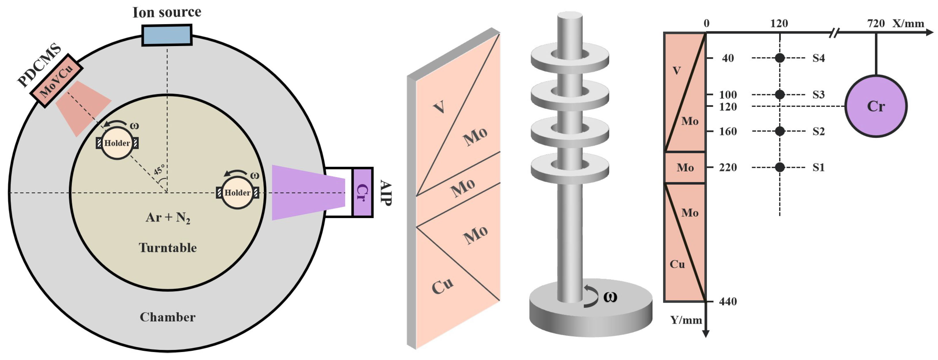
2. Experimental Details

2.1. Coating Deposition

The MoVCuN coatings were prepared on polished WC-Co cemented carbides and 316 L stainless steels by ion-source-assisted pulsed dc magnetron sputtering. the coatings deposited on the cemented carbide substrates were used for microstructure characterization and mechanical properties testing, while the coatings deposited on the stainless steel substrates were used for residual stress testing. The schematic figure of the Mo-V-Cu (99.9% purity, 69 mm × 443 mm) and Cr (99.99% purity, Ø100 × 20 mm) target positions is shown in Figure 1, and the vertical distance of the sample varied from 40 to 220 mm. All the substrates were dried prior to their installation on the substrate carrier following a 20 min ultrasonic cleaning procedure utilizing acetone and alcohol. Then, the chamber was pumped up to 4.0 × 10⁻³ Pa prior to deposition, with substrate temperature maintained at 200 °C. The substrates were subjected to Ar+ bombardment for 15 min at a 40% duty cycle and −1000 V bias voltage in order to eliminate the surface contaminants. To improve the adhesion strength between the coating and substrate, arc ion plating (AIP) with a Cr target was used to deposit a thin CrN sublayer for 5 min, operating at a target current of 100 A and a substrate bias voltage of −150 V. Then, this was followed by the deposition of MoVCuN coatings using pulsed dc magnetron sputtering with ALIS assistance for 500 min, operating at 1.5 kW target power and a duty cycle of 75%, and an ion source power of 0.6 kW. A mixed gas of N2 (10 sccm) and Ar (35 sccm) was introduced, the total gas pressure was controlled at 0.5 Pa by adjusting throttle valve, and the substrate holder was rotated at 3 rpm during deposition.

2.2. Coating Characterization

Scanning electron microscopy (SEM, Nano430, Amsterdam, The Netherlands) with EDS was utilized to characterize the morphologies and chemical composition of the coatings. The coating thickness was directly measured through the cross-section images observed by SEM; then, the deposition rate could be calculated. The characterization of crystal structure was performed using X-ray diffraction (XRD, Bruker D8 advance, Karlsruhe, Germany) with Cu Kα radiation and a scanning angle ranging from 30° to 90° at a step size of 0.02°. The preferable orientation was determined using the texture coefficient formula [29]:
T ( h k l )   =   I ( h k l ) / I 0 ( h k l ) 1 n n = 1 n I ( h k l ) / I 0 ( h k l )
where I0(hkl) and I(hkl) refer to the relative standard intensity of the MoN powder and intensity of the measured (hkl) peak, respectively, and n refers to the reflection number. The determination of surface roughness was carried out by atomic force microscope (AFM, Bruker dimension Icon, Karlsruhe, Germany), operating in a contact mode with a 5 × 5 μm2 scan area. The characterization of the chemical structure was performed using X-ray photoelectron spectroscopy (XPS, Escalab 250Xi, Waltham, MA, USA) with Al Kα X-ray source. The residual stress was measured using a film stress tester (FST-1000, Supro Instruments, Shenzhen, China), in accordance with the substrate curvature method based on Stoney’s equation [30]:
σ s = E s 6 ( 1 υ s ) h s 2 h c ( 1 R 1 R 0 )
where Es and υs refer to the Elastic modulus and Poisson’s ratio of the substrate, respectively. hs and hc denote the thickness of the substrate and coating, respectively. R0 and R represent the curvature radius of the substrate before and after deposition, respectively. The hardness and elastic modulus were assessed using a nanoindentation tester (NHT2, CSM, Peseux, Switzerland), and a minimum of five indentations were made per sample. The adhesion strength was assessed by a scratch tester (RST, CSM, Peseux, Switzerland) operating at a maximal load of 100 N and a scratch length of 3 mm. Optical microscopy (OM) was then employed to examine the scratch images, and at least three scratches were made for each sample.

3. Results and Discussion
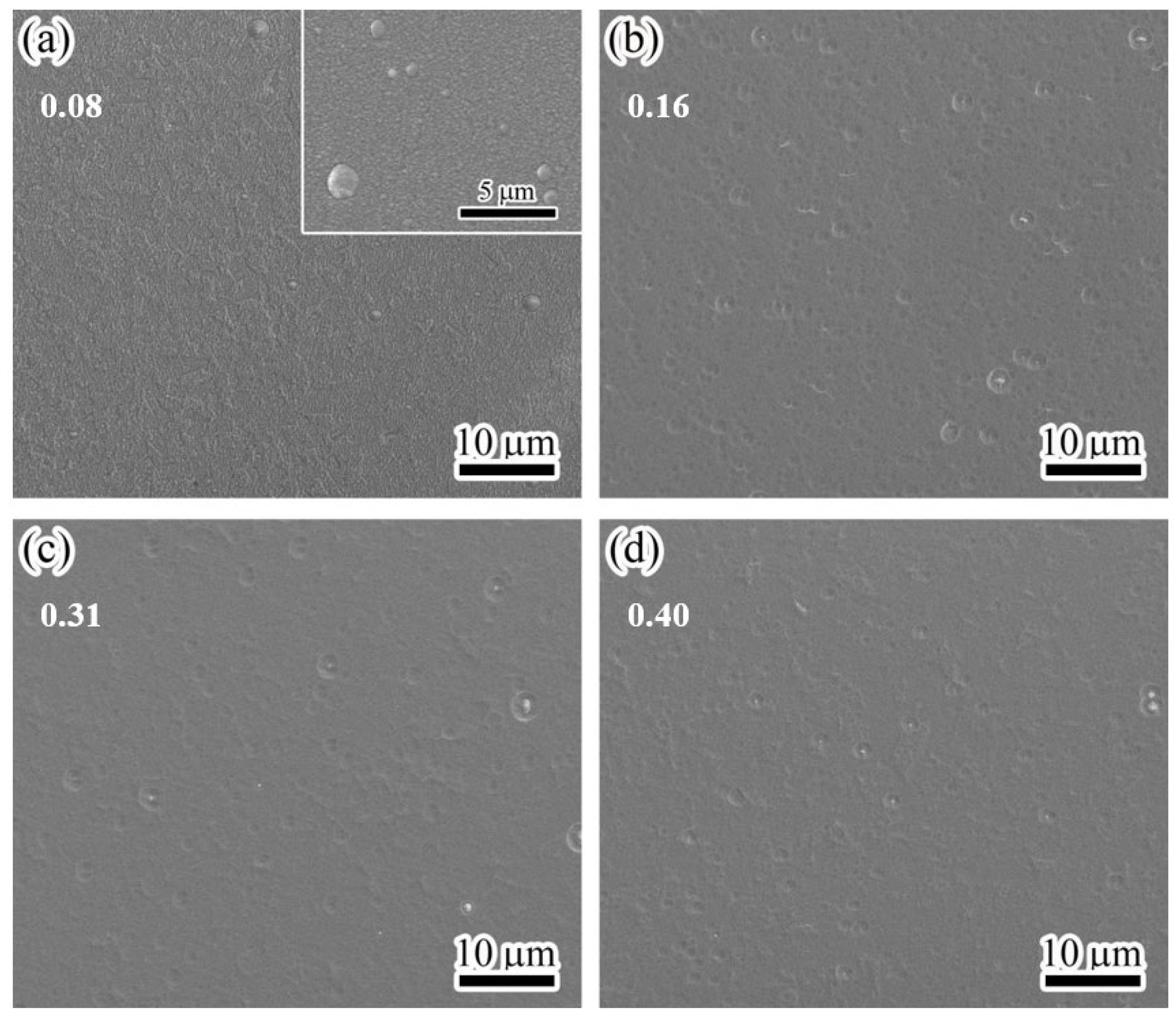
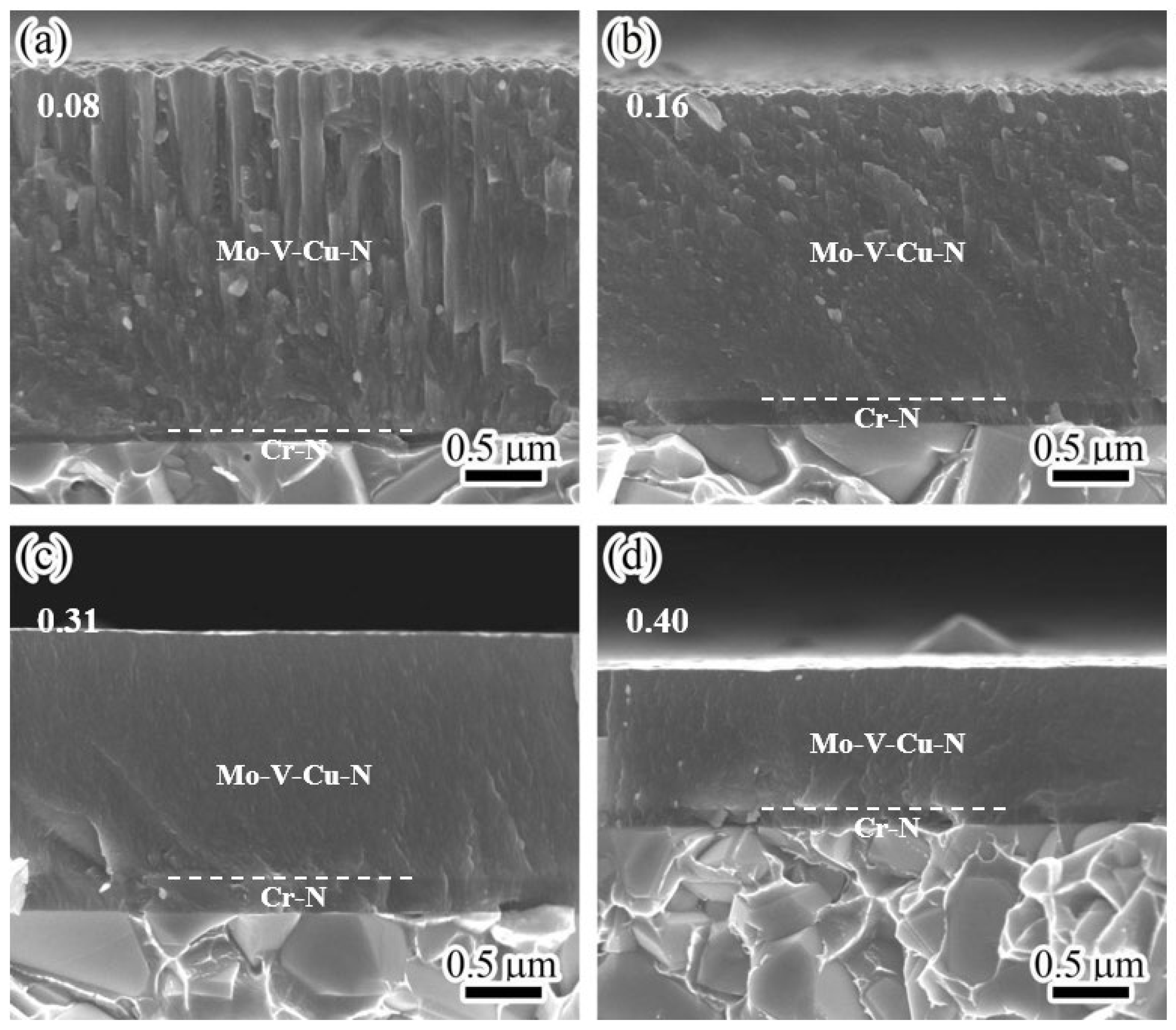
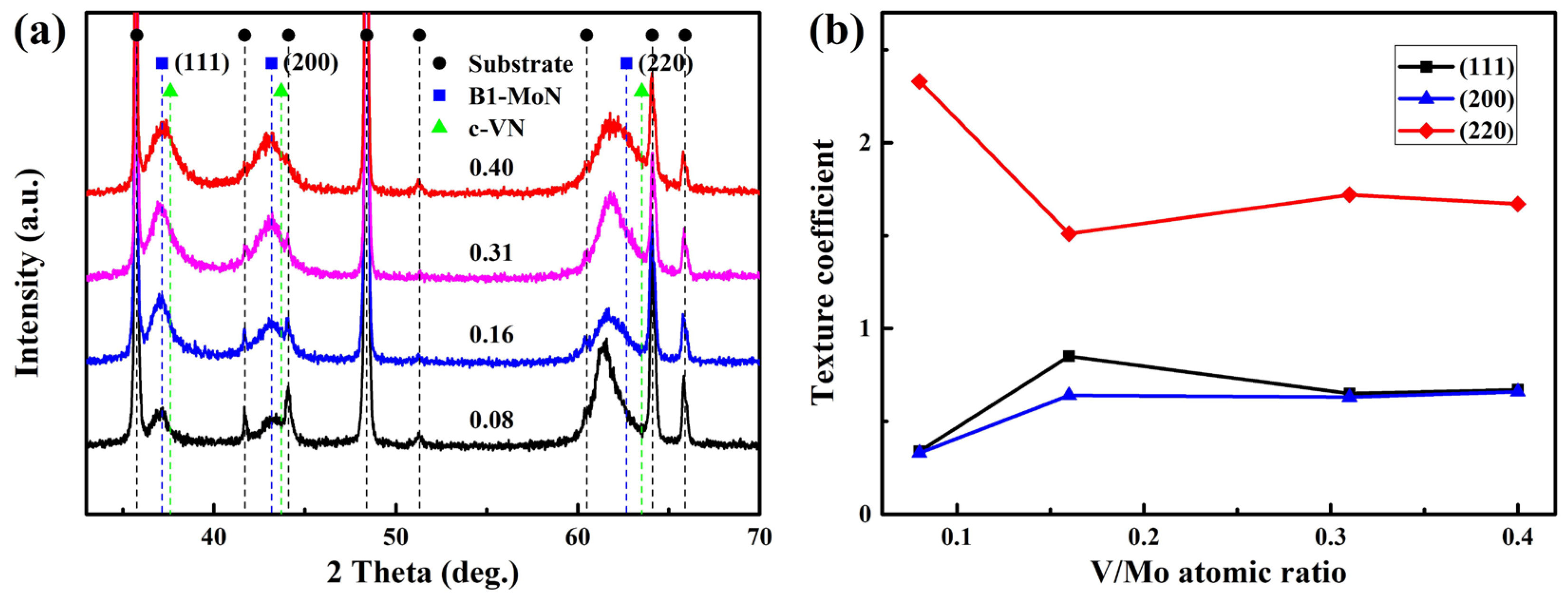
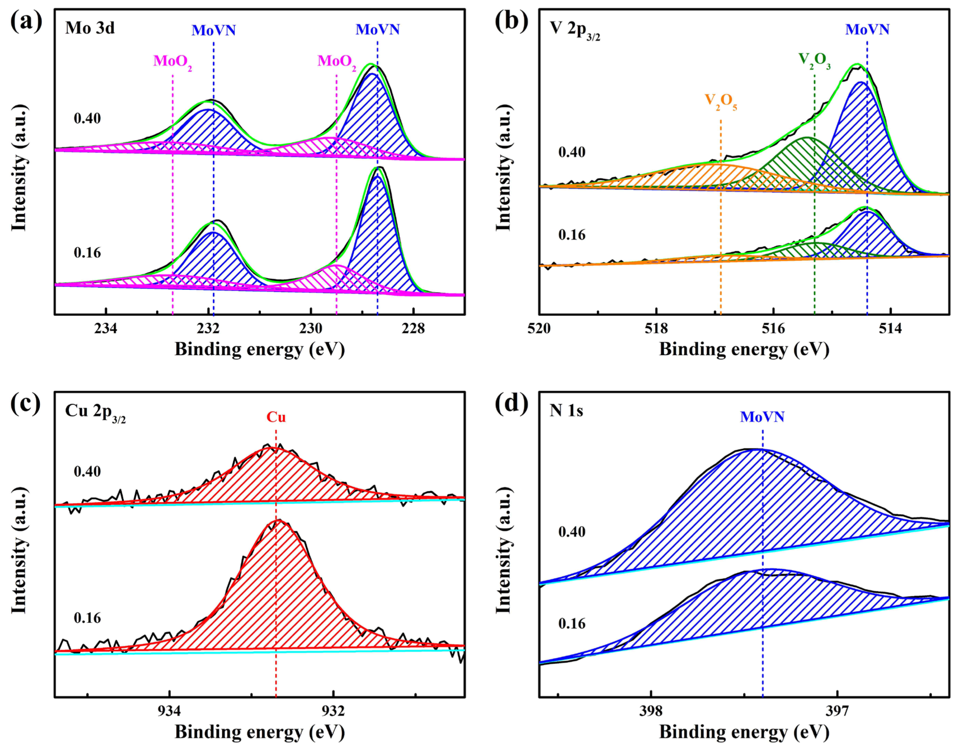
3.1. Microstructure

Table 1 presents a list of the chemical composition of MoVCuN coatings. Due to the special design of the relative position between the target and sample (in Figure 1), coatings with varying compositions can be obtained. With the decrease in the sample distance from 220 to 40 mm, the Mo content gradually decreased from 54.8 to 39.5 at.%, and the Cu content slightly decreased from 0.6 at.% to 0.3 at.%. Correspondingly, the contents of V and N gradually increased from 4.4 at.% and 40.2 at.% to 15.9 at.% and 44.3 at.%, respectively. The calculated N/(Mo + V) atomic ratio gradually increased from 0.68 to 0.80, implying that all the coatings were substoichiometric, and the V/Mo atomic ratio gradually increased from 0.08 to 0.40. With an increase in the V/Mo atomic ratio, the coating thickness gradually decreased, along with a gradual decrease in the deposition rate from 4.7 to 1.8 nm/min, as shown in Figure 2. Such a decrease in the deposition rate can be related to the different sputtering yields of metal targets. Among the Mo-V-Cu targets, the Cu and Mo metal targets with higher sputtering yields were preferentially sputtered during the deposition process, and the V metal target had the lowest sputtering yield [31].
Figure 3 shows the surface morphologies of the MoVCuN coatings at various V/Mo atomic ratios. In Figure 3a, the coating has a rough surface and is covered with many small bulging peaks. In addition, some large microparticles can be observed in the inset high-magnification image. Generally, the advantage of magnetron sputtering is that the coating surface is very smooth, without any microparticles [10,27]. These microparticles were mainly introduced through the deposition of CrN interlayer using arc ion plating (AIP) [7]. During the deposition process, the arc spots generated by arc discharge evaporated the local area of Cr target with a high temperature, and some large metal droplets flew towards the substrate surface before forming some large microparticles, showing a typical growth defect of AIP. However, when the V/Mo atomic ratio increased above 0.16, the coating surfaces became much smoother and denser. Furthermore, due to the combined effects of etching and ion bombardment, obvious shallow pits and small microparticles developed on the coating surfaces. During ion-source-assisted deposition, the ionization rate of sputtered atoms was increased, and the ions accelerated to bombard the coating surface under the substrate bias voltage. When the V/Mo atomic ratio increased, a greater number of accelerated V ions were directed towards the coating surface under substrate bias voltage, thereby enhancing the ion bombardment effect. Prior to coating deposition, the polished cemented carbide substrate showed a low surface roughness of 2.7 nm [12]. However, the surface roughness of the coatings increased sharply. In Figure 4a, a much rougher surface can be observed, which is consistent with the findings obtained by SEM. As the V/Mo atomic ratio increased from 0.08 to 0.31, the surface roughness gradually decreased from 25.6 ± 1.3 nm to 6.9 ± 0.4 nm, and then reached 7.8 ± 0.7 nm at a high V/Mo atomic ratio of 0.40. The variation in the surface roughness was mainly related to the enhanced ion bombardment at higher V/Mo atomic ratios. With the increase in the V/Mo atomic ratio, the thickness of MoVCuN coatings gradually decreased, which also led to a decrease in the surface roughness. In addition, due to the variation in sample position, the thickness of the CrN sublayer first increased and then decreased. As discussed above, the microparticles were mainly introduced by the CrN sublayer; thus, the increase in CrN layer thickness would increase the surface roughness.
Figure 5 displays the cross-sectional morphologies of MoVCuN coatings at various V/Mo atomic ratios. It can be seen that two layers formed in the cross-sections, including the thin interlayer of CrN and the top layer of MoVCuN. Because of the special design of the two target positions (in Figure 1), the thickness of the CrN layer initially increased from 0.07 to 0.22 μm, and then decreased to 0.12 μm, whereas the thickness of the MoVCuN layer gradually decreased from 2.34 to 0.88 μm. At the interlayer interface, all the coatings exhibited good adhesion without any cracks. In Figure 5a, the MoVCuN coating showed a coarse columnar crystal structure. The growth in these coarse columnar crystals ran through the entire thickness of the coating and formed a typical V-shaped columnar crystals structure, contributing to the rough surface morphology depicted in Figure 3a. A similar columnar structure was also demonstrated for the Mo-V-N coatings [10]. With an increase in the V/Mo atomic ratio, the columnar structure became much denser, and the continuous growth of the columnar crystal was gradually interrupted. Compared to the Mo target, the V target has a lower sputtering yield and deposition rate. However, for the magnetron sputtering, due to the limited ionization ratio (10~20%), the sputtered V atoms have a higher metal ionization ratio per unit deposition time. Thus, the increased V/Mo atomic ratios resulted in higher metal ionization ratios of Mo and V atoms. These ions were accelerated to bombard the coating surface under substrate bias voltage, thereby intensifying the ion bombardment effect. Strong ion bombardment increased the mobility of surface adatom during deposition, resulting in the formation of a dense and fine columnar crystal morphology [12,32].
Figure 6 shows the XRD pattern and texture coefficient of the MoVCuN coatings at various V/Mo atomic ratios. As shown in Figure 6a, three broad diffraction peaks in the coatings appeared at about 37.1°, 43.2°, and 61.5°, corresponding to the (111), (200), and (220) planes of the face-center-cubic (FCC) phase, respectively. Due to the similar diffraction peak positions, the diffraction peaks of the thin layer of Cr-N would be covered by that of the top layer of Mo-V-Cu-N. In addition, some sharp diffraction peaks were observed, corresponding to the diffraction peaks in the WC-Co cemented carbide substrate. The major phase of Mo-N was observed in the XRD patterns as a result of the relatively high Mo content (39.5~54.8 at.%) in the coatings. As a result of their comparable atomic radius, V atoms showed a tendency to partially substitute for Mo atoms in the Mo-N lattice, thereby facilitating the formation of a solid solution phase of Mo-V-N [7]. A similar solid solution phase of FCC Mo-V-N was also found in the Mo-V-N [10] and V1-xMoxN coatings [33]. However, the absence of a diffraction peak associated with the Cu phase in XRD patterns necessitates additional XPS analysis, as the Cu atoms were present in relatively low contents (0.3~0.6 at.%). Related research has indicated that, in the Mo-Cu-N [2] and Mo-V-Cu-N [28] coatings, Cu atoms predominantly existed in an amorphous state when the Cu content was below 11 at.%. In Table 2, the lattice parameters of the coatings were calculated from the (111), (200), and (220) planes in the XRD patterns by using Gaussian fitting [34]. With an increase in the V/Mo atomic ratio, the lattice parameter varied in a small range of from 4.215 to 4.204 Å, corresponding to the FCC B1-MoN phase, a metastable phase characterized by a lattice parameter ranging from 4.20 to 4.27 Å [35]. Thus, the MoVCuN coatings showed a single solid solution phase consisting of FCC B1-MoVN. In previous study [12], due to the low N contents (23.9~42.5 at.%), the γ-Mo2(V)N phase with lattice parameters of 4.162~4.197 Å formed in the MoVCuN coatings. Furthermore, the grain sizes of the (111), (200), and (220) peaks in the B1-MoVN phase were estimated by Scherrer formula [36], as listed in Table 2. As the V/Mo atomic ratio increased, the average grain size gradually decreased from 7.0 to 5.1 nm, indicating that grain refinement occurred, which could be related to the enhanced ion bombardment effect [37]. In addition, as the thickness increased, the crystallinity of the coating increased. Thus, a decrease in the thickness of MoVCuN coatings also contributed to a decrease in the grain size. In Figure 6b, based on the (111), (200), and (220) peaks, the evaluation of the preferred orientation was conducted by the texture coefficient T(hkl) using Equation (1). The (220) plane demonstrated the highest texture coefficient, ranging from 1.51 to 2.33. This indicated that all the coatings exhibited a prominent (220) preferred orientation. According to the growth kinetic model [38], the (220) plane with the most open channeling directions has a higher probability of survival than the (111) and (200) planes due to the anisotropy of the collision effect. A similar (220) preferred orientation was also observed for the AlTiVCuN coatings deposited by ALIS-assisted magnetron sputtering [39] and HIPIMS [40].
Figure 7 illustrates the fitted XPS spectra of the MoVCuN coatings at various V/Mo atomic ratios. The deconvolution of the asymmetric Mo 3d peak into four peaks, as shown in Figure 7a, can correspond to the major peaks in MoVN (Mo 3d5/2: 228.7 eV, Mo 3d3/2: 231.9 eV), along with the minor peaks in MoO2 (Mo 3d5/2: 229.5 eV, Mo 3d3/2: 232.7 eV) [41]. The minor oxide peaks can be caused by the slight oxidation of the coating surface. In Figure 7b, the fitted spectra of V2p3/2 comprised three sub-peaks: a major peak of MoVN at 514.4 eV, and two oxide peaks of V2O3 and V2O5 at 515.3 eV and 516.9 eV, respectively. In Figure 7c, only one peak was identified, at about 932.7 eV, in the spectra of Cu 2p3/2, which could belong to the metallic Cu [2]. This provided evidence that the Cu atoms in the coatings existed as metallic species rather than existing in nitride form. Similarly, the N 1s spectra only showed a single peak, possibly the MoVN peak, at 397.4 eV binding energy. Consistent with the XRD data mentioned earlier, this demonstrated the formation of a Mo-V-N solid solution phase. With an increase in the V/Mo atomic ratio, the peak areas of both Mo 3d and Cu 2p3/2 spectra decreased, while the peak areas of V 2p3/2 and N 1s spectra significantly increased, which was consistent with the variation in the chemical composition of the coatings, as listed in Table 3. Due to the surface adsorption of pollutants and trace oxides, a large amount of O and C elements were also detected.

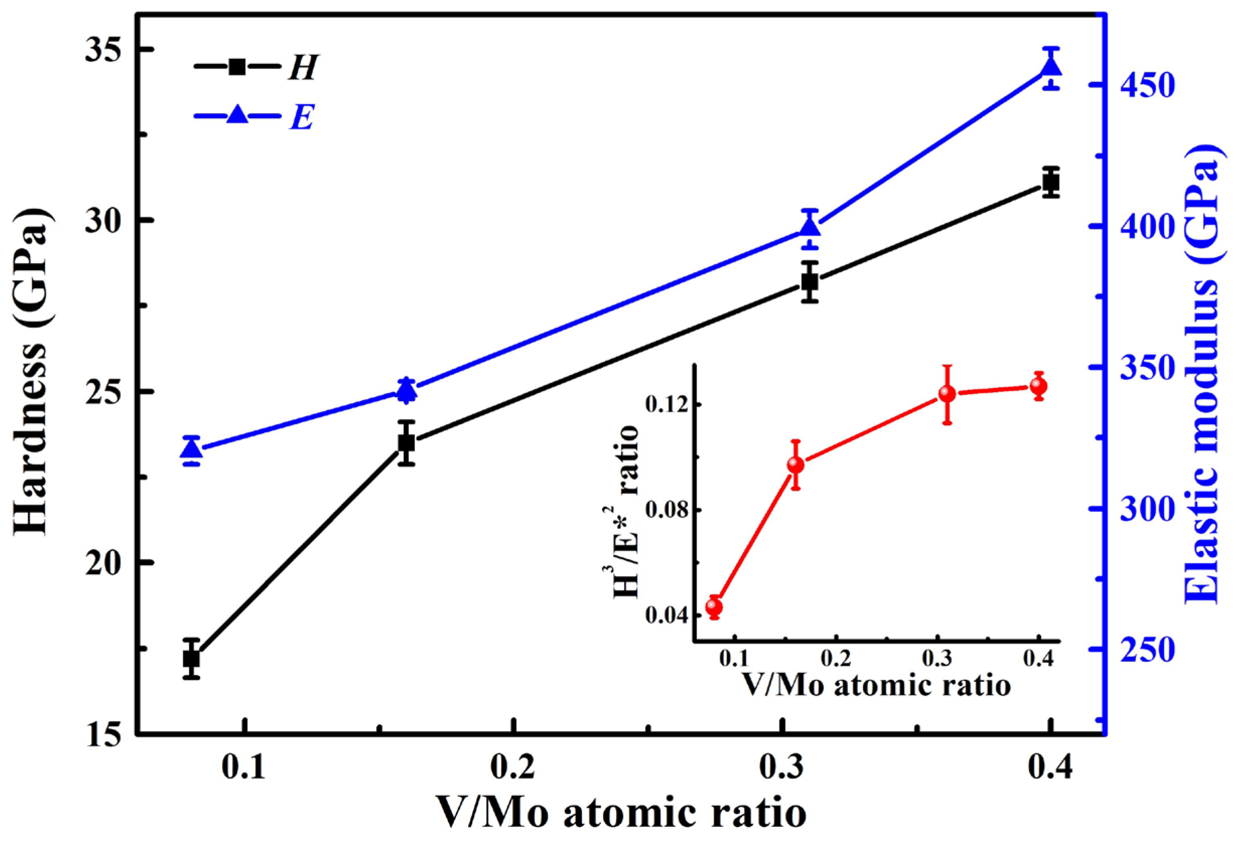
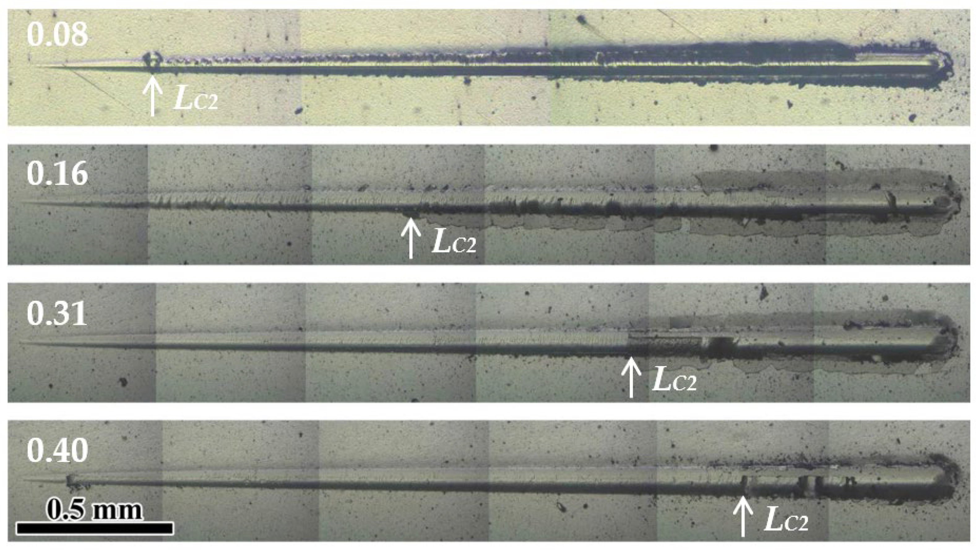
3.2. Mechanical Properties

Generally, the residual stress of the coatings or films includes thermal stress and intrinsic stress. Thermal stress is usually caused by the discrepancy in thermal expansion between the substrate and coating. As for the nitride coatings, due to their lower coefficient of thermal expansion, compressive thermal stress occurs. As for the sputter-deposited coatings, the intrinsic stress is usually caused by the deposition conditions [42], such as working temperature, gas pressure, and substrate bias voltage. Figure 8 presents the residual stress of the coatings at various V/Mo atomic ratios. The negative value of the residual stress calculated for the coatings suggests the formation of compressive residual stress in the coatings. With an increase in the V/Mo atomic ratio, the compressive residual stress gradually increases from 2.9 GPa to 4.1 GPa, which can be explained by several different factors. First, at higher V/Mo atomic ratios, the ion bombardment effect is enhanced, increasing the defect concentration of the coatings, leading to an increase in compressive residual stress [43]. Second, the increase in compressive residual stress may be associated with a slight decrease in the content of Cu, as a result of the ductile Cu phase presented in the coatings. Similar findings were found for the Mo-Cu-N [3] and Al-Ti-V-Cu-N [40] coatings: the relaxation of compressive residual stress occurs at higher Cu contents. Finally, the increase in residual stress may also be associated with the decrease in the coating thickness in Figure 5. For thinner coatings (≤4 μm), the residual stress was found to decrease with the increase in coating thickness [44].
Figure 9 displays the elastic modulus and hardness of the coatings at various V/Mo atomic ratios. To reduce the effect of the cemented carbide substrate and CrN sublayer, the maximum indentation depth was maintained at less than 10~15% of the thickness of MoVCuN coatings. At a low V/Mo atomic ratio of 0.08, the MoVCuN coating demonstrated a low hardness of 17.2 GPa and a low elastic modulus of 320.3 GPa, which can be attributed to the formation of a coarse columnar crystal structure within the coating. With an increase in the V/Mo atomic ratio, the hardness and elastic modulus gradually increased from to 31.1 and 455.9 GPa, respectively. This could be explained by many factors, including the microstructure evolution, and variations in Cu content, residual stress and grain size. First, the increase in hardness can be ascribed to the microstructure densification. With increasing V/Mo atomic ratio, the coatings transformed from a coarse into a dense columnar structure due to the enhanced ion bombardment effect. Furthermore, the enhanced hardness was also associated with the solution-strengthening effect of the B1-MoVN phase. Similar results have been reported for the Mo-V-N [10] and Mo-V-Cu-N [12] coatings with increases in the V content. Second, as a soft metal, the slight decrease in Cu content (0.6~0.3 at.%) was also correlated with enhanced hardness. It was also discovered that the hardness of TiAlN/Cu coatings progressively decreased when the Cu content increased, ranging from 0 to 1.4 at.% [45]. Third, the increase in compressive residual stress also contributed to an improvement in hardness. By restraining the grain sliding and grain rotation, the high compressive residual stress could help to resist plastic deformation in the coatings and increase the coating hardness. Finally, the increased hardness was also related to a decrease in the grain size. Based on the Hall–Petch effect, the hardness of BN coatings was effectively improved by decreasing the grain size [46,47]. With an increase in the V/Mo atomic ratio, the H3/E*2 ratio gradually increased from 0.04 to 0.13, implying that the ability to resist crack initiation and the propagation of the coatings was improved.
Figure 10 presents scratch images of the coatings at various V/Mo atomic ratios. Generally, the adhesive failure mode LC2, characterized by adhesive chipping at the track edges, was employed to assess the adhesion strength between the substrate and coating. At a low V/Mo atomic ratio of 0.08, the adhesive chipping occurred at the initial stage of the scratch test, and numerous adhesive fragments were dispersed along the track edge, indicating a low adhesion strength, which could be caused by the low H3/E*2 ratio of 0.04. Similar results were also found for the MoVCuN [12] and AlTiVCuN [48] coatings with low H3/E*2 ratios. However, when the V/Mo atomic ratio increased to above 0.16, smooth scratch morphologies can be observed in the initial stages, and adhesive chipping started in the middle or later stages, implying a significant improvement in the adhesion strength of the coatings. In Figure 11, with increasing the V/Mo atomic ratio, a gradual increase in the adhesion strength was observed from 14.4 to 78.7 N, which was mainly attributed to an increase in the H3/E*2 ratio. The increase in adhesion strength was also associated with the presence of Cu content in the coatings. The addition of Cu adversely influenced the coating/substrate bond, resulting in a lower adhesion strength and lower energy for the Cu-containing coatings [3]. Moreover, the increase in adhesion strength was also related to an increase in the thickness of the CrN sublayer used to improve the adhesion strength between the coating and substrate.

4. Conclusions

In this study, the MoVCuN coatings were deposited using pulsed dc magnetron sputtering with ALIS assistance, and the relationship between the microstructure evolution, mechanical properties, surface roughness, and the residual stress was investigated. The primary findings can be summarized as follows:
(1)
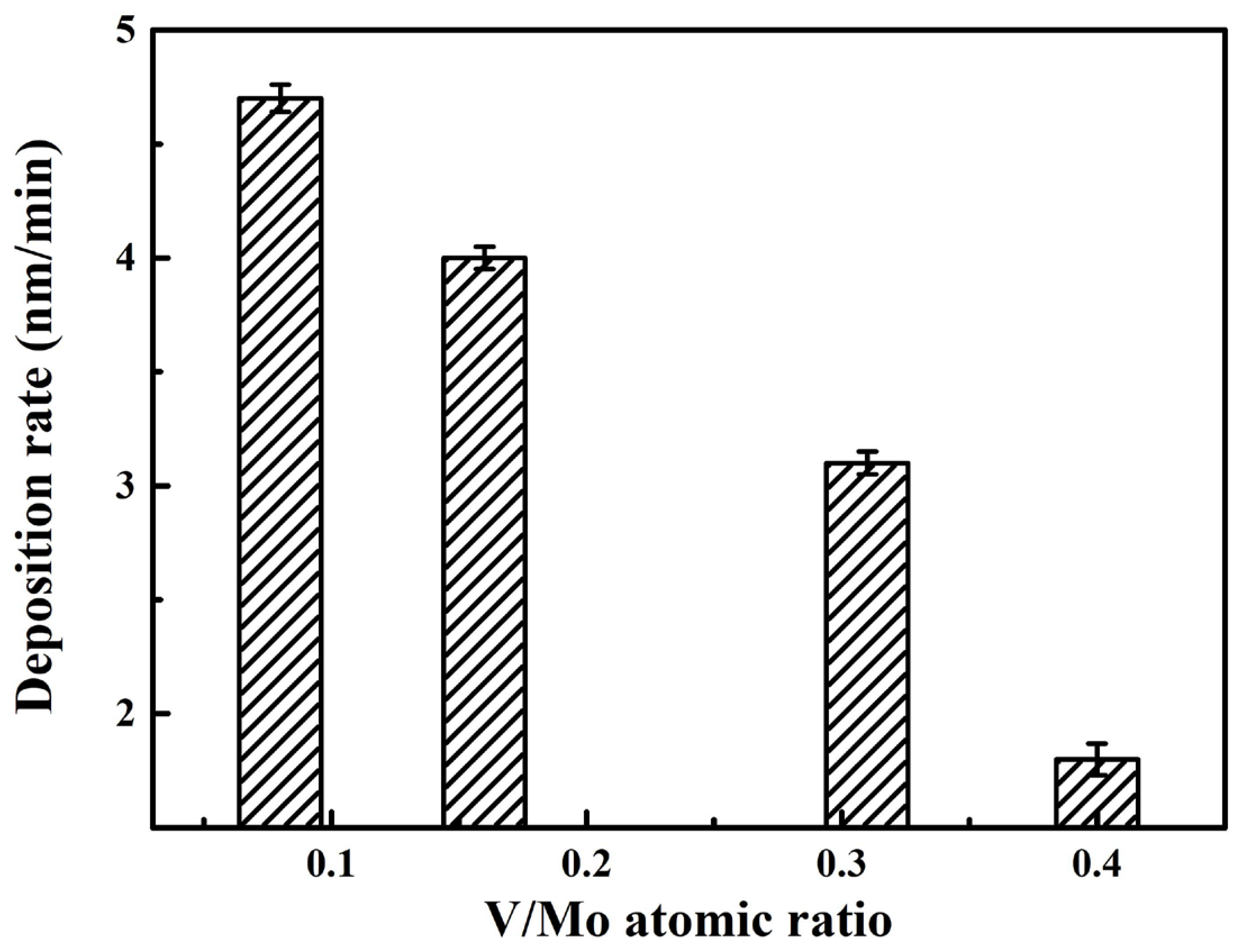
As the V/Mo atomic ratio increased, the deposition rate sharply decreased from 4.7 to 1.8 nm/min, the average surface roughness of the coatings gradually decreased.
(2)
The MoVCuN coatings exhibited a solid solution phase of FCC B1-MoVN with a strong (220) preferred orientation. As the V/Mo atomic ratio increased, the coatings transformed from a coarse to a dense columnar crystal structure, and promoted grain refinement.
(3)
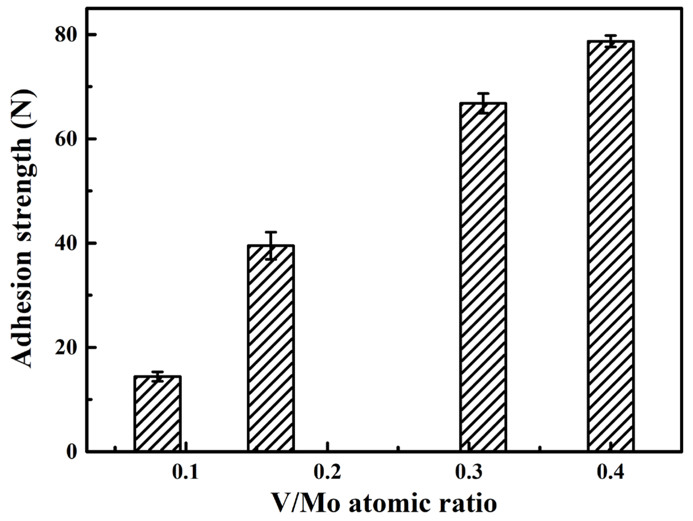
With an increase in the V/Mo atomic ratio, the ion bombardment effect was enhanced, contributing to a gradual increase in the compressive residual stress, hardness, and adhesion strength of the coatings.

Author Contributions

Writing original manuscript and experimental, H.M.; experiment and characterization, C.L., Y.L. and Y.S.; data analysis and formal analysis, Q.L. and R.W.; resources and conceptualization, W.Z. and W.M.; manuscript revision and funding acquisition, W.G. All authors have read and agreed to the published version of the manuscript.

Funding

This research was supported by the International Science and Technology Cooperation Project of Guangdong Province (2019A050510049), Professorial and Doctoral Scientific Research Foundation of Huizhou University (2020JB010), Indigenous Innovation’s Capability Development Program of Huizhou University (HZU202005), the National College Student Innovation Training Program (202310577004), and the Innovative Research Team of Guangdong Province and Huizhou University (IRTHZU).

Institutional Review Board Statement

Not applicable.

Informed Consent Statement

Not applicable.

Data Availability Statement

The data presented in this study are available on request from the corresponding author.

Conflicts of Interest

Author Wenjun Zeng was employed by the company Hunan Yongshan Lithium Industry Co., Ltd. Author Wenbao Mei was employed by the company Shenzhen Qiling Image Technology Co., Ltd. The remaining authors declare that the research was conducted in the absence of any commercial or financial relationships that could be construed as a potential conflict of interest.

References

  1. Kim, J.N.; Park, S.; Kim, T.; Lee, J.J. Structure and mechanical properties of Mo-N/Cu films produced by inductively coupled plasma reactive sputtering. Thin Solid Films 2011, 519, 6876–6880. [Google Scholar] [CrossRef]
  2. Shin, J.H.; Wang, Q.M.; Kim, K.H. Microstructural evolution and tribological behavior of Mo-Cu-N coatings as a function of Cu content. Mater. Chem. Phys. 2011, 130, 870–879. [Google Scholar] [CrossRef]
  3. Pappacena, K.E.; Singh, D.; Ajayi, O.O.; Routbort, J.L.; Erilymaz, O.L.; Demas, N.G.; Chen, G. Residual stresses, interfacial adhesion and tribological properties of MoN/Cu composite coatings. Wear 2012, 278–279, 62–70. [Google Scholar] [CrossRef]
  4. Xu, X.; Su, F.; Li, Z. Microstructure and tribological behaviors of MoN-Cu nanocomposite coatings sliding against Si3N4 ball under dry and oil-lubricated conditions. Wear 2019, 434–435, 202994. [Google Scholar] [CrossRef]
  5. Mei, H.; Wang, R.; Zhong, X.; Dai, W.; Wang, Q. Influence of nitrogen partial pressure on microstructure and tribological properties of Mo-Cu-V-N composite coatings with high Cu content. Coatings 2018, 8, 24. [Google Scholar] [CrossRef]
  6. Mei, H.; Luo, Q.; Huang, X.; Ding, J.C.; Zhang, T.F.; Wang, Q. Influence of lubricious oxides formation on the tribological behavior of Mo-V-Cu-N coatings deposited by HIPIMS. Surf. Coat. Technol. 2019, 358, 947–957. [Google Scholar] [CrossRef]
  7. Ding, J.C.; Mei, H.; Li, Q.; Zhao, Z.; Shen, Y.; Cheng, L.; Wang, R.; Gong, W.; Wang, Q. Microstructure, mechanical and tribological properties of Mo-V-Cu-N coatings prepared by HIPIMS technique. Ceram. Int. 2022, 48, 10704–10712. [Google Scholar] [CrossRef]
  8. Gassner, G.; Mayrhofer, P.H.; Kutschej, K.; Mitterer, C.; Kathrein, M. Magnéli phase formation of PVD Mo-N and W-N coatings. Surf. Coat. Technol. 2006, 201, 3335–3341. [Google Scholar] [CrossRef]
  9. Wang, T.; Zhang, G.; Liu, Z.; Jiang, B. Oxidation behavior of magnetron sputtered Mo2N/AlN multilayer coatings during heat treatment. Ceram. Int. 2015, 41, 7028–7035. [Google Scholar] [CrossRef]
  10. Wang, W.; Zheng, S.; Pu, J.; Cai, Z.; Wang, H.; Wang, L.; He, G. Microstructure, mechanical and tribological properties of Mo-V-N films by reactive magnetron sputtering. Surf. Coat. Technol. 2020, 387, 125532. [Google Scholar] [CrossRef]
  11. Mei, H.; Ding, J.C.; Wang, R.; Li, Q.; Zhao, Z.; Long, D.; Wei, X.; Cai, S.; Gong, W.; Wang, Q. Relationship between oxidation behavior and tribological properties of Mo-V-Cu-N coatings. Surf. Coat. Technol. 2022, 451, 129067. [Google Scholar] [CrossRef]
  12. Mei, H.; Cai, Z.; Ding, J.; Yan, K.; Li, Q.; Zhao, Z.; Zhao, J.; Cheng, L.; Liu, M.; Gong, W. The additions of V and Cu on the microstructure and mechanical properties of Mo-N coatings. Coatings 2022, 12, 1129. [Google Scholar] [CrossRef]
  13. Kelly, P.J.; Arnell, R.D. Magnetron sputtering: A review of recent developments and applications. Vacuum 2000, 56, 159–172. [Google Scholar] [CrossRef]
  14. Park, Y.S.; Myung, H.S.; Han, J.G.; Hong, B. Characterization of CNx thin films prepared by close field unbalanced magnetron sputtering. Thin Solid Films 2005, 475, 298–302. [Google Scholar] [CrossRef]
  15. Lin, J.; Zhang, N.; Sproul, W.D.; Moore, J.J. A comparison of the oxidation behavior of CrN films deposited using continuous dc, pulsed dc and modulated pulsed power magnetron sputtering. Surf. Coat. Technol. 2012, 206, 3283–3290. [Google Scholar] [CrossRef]
  16. Kim, W.R.; Park, M.S.; Jung, U.C.; Kwon, A.R.; Kim, Y.W.; Su, W. Effect of voltage on diamond-like carbon thin film using linear ion source. Surf. Coat. Technol. 2014, 243, 15–19. [Google Scholar] [CrossRef]
  17. Paskvale, S.; Kahn, M.; Čekada, M.; Panjan, P.; Waldhauser, W.; Podgornik, B. Tribological properties of diamond-like carbon coatings prepared by anode layer source and magnetron sputtering. Surf. Coat. Technol. 2011, 205, S99–S102. [Google Scholar] [CrossRef]
  18. Ding, J.C.; Zhang, T.F.; Mane, R.S.; Kim, K.H.; Kang, M.C.; Zou, C.W.; Wang, Q.M. Low-temperature deposition of nanocrystalline Al2O3 films by ion source- assisted magnetron sputtering. Vacuum 2018, 149, 284–290. [Google Scholar] [CrossRef]
  19. Tang, Y.; Li, Y.S.; Yang, Q.; Hirose, A. Characterization of hydrogenated amorphous carbon thin films by end-Hall ion beam deposition. Appl. Surf. Sci. 2011, 257, 4699–4705. [Google Scholar] [CrossRef]
  20. Pan, Y.Q.; Yin, Y. Diamond-like carbon films with End-Hall ion source enhanced chemical vapour deposition. Diam. Relat. Mater. 2007, 16, 220–224. [Google Scholar] [CrossRef]
  21. Kaufman, H.R.; Cuomo, J.J.; Harper, J.M.E. Technology and applications of broad-beam ion sources used in sputtering, Part I. Ion source technology. J. Vac. Sci. Technol. 1982, 21, 725–736. [Google Scholar] [CrossRef]
  22. Gablech, I.; Svatoš, V.; Caha, O.; Dubroka, A.; Pekárek, J.; Klempa, J.; Neužil, P.; Schneider, M.; Šikola, T. Preparation of high-quality stress-free (001) aluminum nitride thin film using a dual Kaufman ion-beam source setup. Thin Solid Films 2019, 670, 105–112. [Google Scholar] [CrossRef]
  23. Tian, S.; Xu, F.; Ye, P.; Wu, J.; Zou, Y.; Zuo, D. Deposition of cubic boron nitride films by anode layer linear ion source assisted radio frequency magnetron sputtering. Thin Solid Films 2018, 653, 13–18. [Google Scholar] [CrossRef]
  24. Ye, P.; Xu, F.; Wu, J.X.; Tian, S.; Zhao, X.R.; Tang, X.L.; Zuo, D.W. Effects of anode layer linear ion source on the microstructure and mechanical properties of amorphous carbon nitride films. Surf. Coat. Technol. 2017, 320, 183–189. [Google Scholar] [CrossRef]
  25. Qasim, A.M.; Ali, F.; Wu, H.; Fu, R.K.Y.; Xiao, S.; Li, Y.; Wu, Z.; Chu, P.K. Enhanced mechanical and electrochemical properties of TiNx thin films prepared by magnetron sputtering with an anode layer ion source. Surf. Coat. Technol. 2019, 365, 253–260. [Google Scholar] [CrossRef]
  26. He, Z.; Zhang, S.; Sun, D. Effect of bias on structure mechanical properties and corrosion resistance of TiNx films prepared by ion source assisted magnetron sputtering. Thin Solid Films 2019, 676, 60–67. [Google Scholar] [CrossRef]
  27. Mei, H.; Zhao, S.; Wu, Z.; Dai, W.; Wang, Q. Effect of nitrogen partial pressure on microstructure and mechanical properties of Mo-Cu-V-N composite coatings deposited by HIPIMS. Surf. Coat. Technol. 2017, 329, 68–76. [Google Scholar] [CrossRef]
  28. Mei, H.; Ding, J.; Zhao, J.; Wang, T.; Huang, K.; Guo, Z.; Luo, Q.; Gong, W. Effect of charge voltage on the microstructural, mechanical, and tribological properties of Mo-Cu-V-N nanocomposite coatings. Coatings 2021, 11, 1565. [Google Scholar] [CrossRef]
  29. Cheng, H.E.; Hon, M.H. Texture formation in titanium nitride films prepared by chemical vapor deposition. J. Appl. Phys. 1996, 79, 8047–8053. [Google Scholar] [CrossRef]
  30. Stoney, G.G. The tension of metallic films deposited by electrolysis. Proc. R. Soc. Lond. Ser. A 1909, 82, 172–175. [Google Scholar]
  31. Laegreid, N.; Wehner, G.K. Sputtering yields of metals for Ar+ and Ne+ ions with energies from 50 to 600 ev. J. Appl. Phys. 1961, 32, 365–369. [Google Scholar] [CrossRef]
  32. Petrov, I.; Barna, P.B.; Hultman, L.; Greene, J.E. Microstructural evolution during film growth. J. Vac. Sci. Technol. A 2003, 21, S117–S128. [Google Scholar] [CrossRef]
  33. Mikula, M.; Uzon, S.; Hudec, T.; Grančič, B.; Truchlý, M.; Roch, T.; ŠvecJr, P.; Satrapinskyy, L.; Čaplovičová, M.; Greczynski, G.; et al. Thermally induced structural evolution and age-hardening of polycrystalline V1-xMoxN (x ≈ 0.4) thin films. Surf. Coat. Technol. 2021, 405, 126723. [Google Scholar] [CrossRef]
  34. Luo, Q. Characterization of short-range ordered domains using quantitative X-ray diffraction. Nanosci. Nanotech. Let. 2018, 10, 835–842. [Google Scholar] [CrossRef]
  35. Ihara, H.; Kimura, Y.; Senzaki, K.; Kezuka, H.; Hirabayashi, M. Electronic structures of B1 MoN, fcc Mo2N, and hexagonal MoN. Phys. Rev. B 1985, 31, 3177–3178. [Google Scholar] [CrossRef] [PubMed]
  36. Patterson, A.L. The Scherrer formula for X-ray particle size determination. Phys. Rev. 1939, 56, 978–982. [Google Scholar] [CrossRef]
  37. Zheng, J.; Zhou, H.; Gui, B.; Luo, Q.; Li, H.; Wang, Q. Influence of power pulse parameters on the microstructure and properties of the AlCrN coatings by a modulated pulsed power magnetron sputtering. Coatings 2017, 7, 216. [Google Scholar] [CrossRef]
  38. Abadias, G. Stress and preferred orientation in nitride-based PVD coatings. Surf. Coat. Technol. 2008, 202, 2223–2235. [Google Scholar] [CrossRef]
  39. Mei, H.; Yan, K.; Wang, R.; Cheng, L.; Li, Q.; Zhao, Z.; Ding, J.C.; Gong, W. Microstructure and mechanical properties of AlTiVCuN coatings prepared by ion source-assisted magnetron sputtering. Nanomaterials 2023, 13, 3146. [Google Scholar] [CrossRef]
  40. Mei, H.; Ding, J.C.; Xiao, X.; Luo, Q.; Wang, R.; Zhang, Q.; Gong, W.; Wang, Q. Influence of pulse frequency on microstructure and mechanical properties of Al-Ti-V-Cu-N coatings deposited by HIPIMS. Surf. Coat. Technol. 2021, 405, 126514. [Google Scholar] [CrossRef]
  41. Kim, G.T.; Park, T.K.; Chung, H.; Kim, Y.T.; Kwon, M.H.; Choi, J.G. Growth and characterization of chloronitroaniline crystals for optical parametric oscillators: I. XPS study of Mo-based compounds. Appl. Surf. Sci. 1999, 152, 35–43. [Google Scholar] [CrossRef]
  42. Windischmann, H. Intrinsic stress in sputter-deposited thin-films. Crit. Rev. Solid State 1992, 17, 547–596. [Google Scholar] [CrossRef]
  43. Ljungcrantz, H.; Hultman, L.; Sundgren, J.-E.; Karlsson, L. Ion induced stress generation in arc-evaporated TiN films. J. Appl. Phys. 1995, 78, 832–837. [Google Scholar] [CrossRef]
  44. Seidl, W.M.; Bartosik, M.; Kolozsvári, S.; Bolvardi, H.; Mayrhofer, P.H. Influence of coating thickness and substrate on stresses and mechanical properties of (Ti,Al,Ta)N/(Al,Cr)N multilayers. Surf. Coat. Technol. 2018, 347, 92–98. [Google Scholar] [CrossRef]
  45. Chen, L.; Pei, Z.; Xiao, J.; Gong, J.; Sun, C. TiAlN/Cu nanocomposite coatings deposited by filtered cathodic arc ion plating. J. Mater. Sci. Technol. 2017, 33, 111–116. [Google Scholar] [CrossRef]
  46. Tian, Y.; Xu, B.; Yu, D.; Ma, Y.; Wang, Y.; Jiang, Y.; Hu, W.; Tang, C.; Gao, Y.; Luo, K.; et al. Ultrahard nanotwinned cubic boron nitride. Nature 2013, 493, 385–388. [Google Scholar] [CrossRef]
  47. Liang, H.; Lin, W.; Wang, Q.; Zhang, W.; Guan, S.; Zhang, J.; Kai, J.J.; He, D.; Peng, F. Ultrahard and stable nanostructured cubic boron nitride from hexagonal boron nitride. Ceram. Int. 2020, 46, 12788–12794. [Google Scholar] [CrossRef]
  48. Mei, H.; Geng, D.; Wang, R.; Cheng, L.; Ding, J.C.; Luo, Q.; Zhang, T.F.; Wang, Q. Effect of Cu doping on the microstructure and mechanical properties of AlTiVN-Cu nanocomposite coatings. Surf. Coat. Technol. 2020, 402, 126490. [Google Scholar] [CrossRef]
Figure 1. Schematic figure of the deposition system and sample position. The vertical positions of samples S1, S2, S3, and S4 correspond to 220 mm, 160 mm, 100 mm, and 40 mm, respectively. The center position of the Cr target corresponds to 120 mm.
Materials 17 00229 g001
Figure 2. Deposition rate of MoVCuN coatings at various V/Mo atomic ratios.
Materials 17 00229 g002
Figure 3. Surface micrographs of MoVCuN coatings at various V/Mo atomic ratios: (a) 0.08, (b) 0.16, (c) 0.31, (d) 0.40. Inset is the high-magnification image.
Materials 17 00229 g003
Figure 4. Surface roughness of MoVCuN coatings at various V/Mo atomic ratios: (a) 0.08, (b) 0.16, (c) 0.31, (d) 0.40.
Materials 17 00229 g004
Figure 5. Cross-sectional micrographs of MoVCuN coatings at various V/Mo atomic ratios: (a) 0.08, (b) 0.16, (c) 0.31, (d) 0.40.
Materials 17 00229 g005
Figure 6. XRD pattern (a) and texture coefficient (b) of MoVCuN coatings.
Materials 17 00229 g006
Figure 7. Fitted XPS spectra of MoVCuN coatings: (a) Mo 3d, (b) V 2p3/2, (c) Cu 2p3/2, (d) N 1s.
Materials 17 00229 g007
Figure 8. Residual stress of MoVCuN coatings at various V/Mo atomic ratios.
Materials 17 00229 g008
Figure 9. Hardness, elastic modulus, and H3/E*2 ratio of MoVCuN coatings.
Materials 17 00229 g009
Figure 10. Scratch images of MoVCuN coatings at various V/Mo atomic ratios.
Materials 17 00229 g010
Figure 11. Adhesion strength of MoVCuN coatings at various V/Mo atomic ratios.
Materials 17 00229 g011
Table 1. Chemical composition of MoVCuN coatings according to EDS analysis; error ± 0.2 at.%.
SampleChemical Composition (at.%)N/(Mo + V) RatioV/Mo RatioThickness (μm)
MoVCuN
S154.84.40.640.20.680.082.3
S250.58.00.441.10.700.162.0
S344.113.70.441.80.720.311.6
S439.515.90.344.30.800.400.9
Table 2. Lattice parameters and grain sizes of Mo-V-Cu-N coatings.
PlaneLattice Parameter a0 (Å)Grain Size (nm)
0.080.160.310.400.080.160.310.40
(111)4.199 4.197 4.197 4.186 8.2 6.7 6.7 6.1
(200)4.185 4.194 4.192 4.199 5.4 5.1 5.1 5.1
(220)4.261 4.243 4.238 4.227 7.4 4.8 5.4 4.2
Mean4.215 4.211 4.209 4.204 7.0 5.5 5.7 5.1
Stdev0.040 0.027 0.025 0.021 1.4 1.0 0.9 1.0
Table 3. Chemical composition of MoVCuN coatings according to XPS analysis.
SampleV/Mo RatioChemical Composition (at.%)
MoVCuNOC
S20.1637.43.61.215.530.212.1
S40.4028.25.70.522.630.512.5
Disclaimer/Publisher’s Note: The statements, opinions and data contained in all publications are solely those of the individual author(s) and contributor(s) and not of MDPI and/or the editor(s). MDPI and/or the editor(s) disclaim responsibility for any injury to people or property resulting from any ideas, methods, instructions or products referred to in the content.

