Article

Three-Dimensional Vibration Model of Cylindrical Shells via Carrera Unified Formulation

1
College of Weapons Engineering, Naval University of Engineering, Wuhan 430033, China
2
Light Alloy Research Institute, Central South University, Changsha 410083, China
3
State Key Laboratory of Precision Manufacturing for Extreme Service Performance, Central South University, Changsha 410083, China
*
Author to whom correspondence should be addressed.
Materials 2023, 16(9), 3345; https://doi.org/10.3390/ma16093345
Submission received: 27 March 2023 / Revised: 13 April 2023 / Accepted: 19 April 2023 / Published: 24 April 2023

Abstract

:
In this paper, we present a novel and unified model for studying the vibration of cylindrical shells based on the three-dimensional (3D) elastic theory and the Carrera Unified Formulation. Our approach represents a significant advancement in the field, as it enables us to accurately predict the vibrational behavior of cylindrical shells under arbitrary boundary conditions. To accomplish this, we expand the axial, circumferential, and radial displacements of the shell using Chebyshev polynomials and Taylor series, thereby reducing the dimensionality of the expansion and ensuring the precision and rigor of our results. In addition, we introduce three groups of artificial boundary surface springs to simulate the general end boundary conditions of the cylindrical shell and coupling springs to strongly couple the two surfaces of the cylindrical shell φ = 0 and φ = 2π to ensure continuity of displacements on these faces. Using the energy function of the entire cylindrical shell model, we obtain the characteristic equation of the system by finding the partial derivatives of the unknown coefficients of displacement in the energy function. By solving this equation, we can directly obtain the vibration characteristics of the cylindrical shell. We demonstrate the convergence, accuracy, and reliability of our approach by comparing our computational results with existing results in the literature and finite element results. Finally, we present simulation results of the frequency features of cylindrical shells with various geometrical and boundary parameters in the form of tables and figures. Overall, we believe that our novel approach has the potential to greatly enhance our understanding of cylindrical shells and pave the way for further advancements in the field of structural engineering. Our comprehensive model and simulation results contribute to the ongoing efforts to develop efficient and reliable techniques for analyzing the vibrational behavior of cylindrical shells.

1. Introduction

The cylindrical shell is one of the most significant and commonly used structural elements in a variety of military and civilian applications. However, due to various complex loads and environmental influences during the working process of cylindrical shell structures, they are prone to phenomena such as vibration and sound radiation. This not only affects their normal function and service life but also poses a threat to personnel safety and environmental protection. Therefore, studying the vibration characteristics of cylindrical shell structures has important theoretical significance and practical value for aspects such as optimizing design, controlling noise, improving reliability, and extending service life.
As shown in Figure 1, it is a simplified artillery model, whose barrel is a typical cylindrical shell structure. Usually, for the study of the dynamics of the gun barrel, the beam theory was mainly used to simplify the modeling [1,2]. Yet in fact, the theory of the beam model only takes into account the radial vibration of the barrel, which cannot describe the complete dynamics of the cylindrical barrel. Therefore, it is necessary to establish the cylindrical shell model using 3D elastic theory for analysis to obtain accurate vibration characteristics of the cylindrical shell.
There is a lot of literature on the 3D vibration studies of cylindrical shells. Liew and Hung [3] used the orthogonal polynomial functions to approximate the displacement field of a solid cylinder and obtained the 3D vibration characteristics of the solid cylinder. Loy and Lam [4] used a layered approach to study the vibration of thick cylindrical shells with simple-support–simple-support and clamped–clamped boundaries. The cylindrical shell was discretized in the thickness direction into an arbitrary number of thin cylindrical layers, and the displacement of each layer was approximated by trigonometric functions in the axial and circumferential directions, as well as some linear shape functions in the thickness direction. Zhou et al. [5] took the Chebyshev polynomials as the admissible functions for cylindrical shells, and then adopted the Ritz method to obtain the vibrations of cylindrical shells. Mofakhami et al. [6] published a general solution to examine the vibration of cylinders with various boundary conditions by using an infinite cylinder solution based on the variable separation approach. Khalili et al. [7] presented the free vibration analysis of isotropic circular cylindrical shells by using the 3D refined higher-order shear deformation theory. On the dynamic response of cylindrical shells, the theory considered the effects of in-plane and rotational inertia, as well as transverse normal and shear strains. Because the stresses over the shell thickness must be integrated over the trapezoidal cross section of the shell elements to obtain accurate stress results, the trapezoidal shape factor of the shell elements was also included. By combining the layered theory with the 3D form of the Hamiltonian principle and the associated boundary conditions, Malekzadeh et al. [8] obtained the equations of motion for a 3D cylindrical shell, and the obtained equations were discretized using the differential product method. Ye et al. [9] proposed a unified solution for the free vibration of thick cylindrical shells, the shell displacements were expanded as a standard Fourier series with auxiliary functions, and the energy functions of the shell were solved by the Rayleigh—Ritz method. Atashipour et al. [10] presented a novel 3D elastic motion including the body force in a cylindrical coordinate system; the 3D static and free vibrations of a hollow cylindrical shell were solved analytically.
At present, there are many different theories applied to the study of vibration of cylindrical shell structures in addition to the three-dimensional theory, which are listed in Table 1. As can be seen from the table, researchers have developed different methods based on different theories to analyze the vibration of cylindrical shell structures of different materials and have obtained a large amount of valuable data.
Recently, there are also some studies on the 3D vibration of composite cylindrical shell structures. Su et al. [21] analyzed the 3D vibration of functionally graded conical and cylindrical shells by using the Modified Fourier series method. Qin et al. [22] used the 3D elastic theory and Rayleigh—Ritz method to analyze the free vibration of functionally graded porous graphene platelet-reinforced composite cylindrical shells. They compared six different types of admissible functions including Chebyshev polynomials of the first kind, Chebyshev polynomials of the second kind, Legendre polynomials, Orthogonal polynomials, Modified Fourier series of the first kind, and Modified Fourier series of the second kind. Thanh et al. [23] presented a 3D numerical solution based on isogeometric analysis to investigate the free vibration of cylindrical shells made of functionally graded porous-cellular materials. Tong et al. [24] proposed a solution for free vibration analysis of arbitrary angle-play laminated cylindrical shells, which combined the state—space technique and differential quadrature method.
The present solution model is established based on the Carrera Unified Formulation (CUF). The CUF was refined by Carrera et al. [25,26,27] after extensive research of typical structures such as beams, plates, and shells. The classical theories such as Kirchhoff and Mindlin shear deformation theories can be derived as special cases of CUF [28,29]. As a powerful general theory, CUF had been successfully applied to shell structures [30,31,32]. In CUF, the displacement fields of structures are generalized and expressed by the polynomials, such as Taylor series and Lagrange polynomials, and the precision of the CUF is primarily determined by the terms of polynomial expansions.
In the present work, a new 3D model based on CUF is proposed for free vibrations of the cylindrical shells with elastically restrained ends. The axial, circumferential and radial displacements of the cylindrical shell are expanded by Chebyshev polynomials and Taylor-like series, and the system characteristic equations are constructed by the 3D elastic shell theory. Three groups of face boundary springs are used to simulate the boundary conditions of two end surfaces of the cylindrical shell, and the two surfaces of the cylindrical shell φ = 0 and φ = 2π are strongly coupled by surface coupling springs. The vibration results of the current solution are proved by comparing them with other methods in literature and FEM software (ABAQUS 2022).

2. Theoretical Formulations

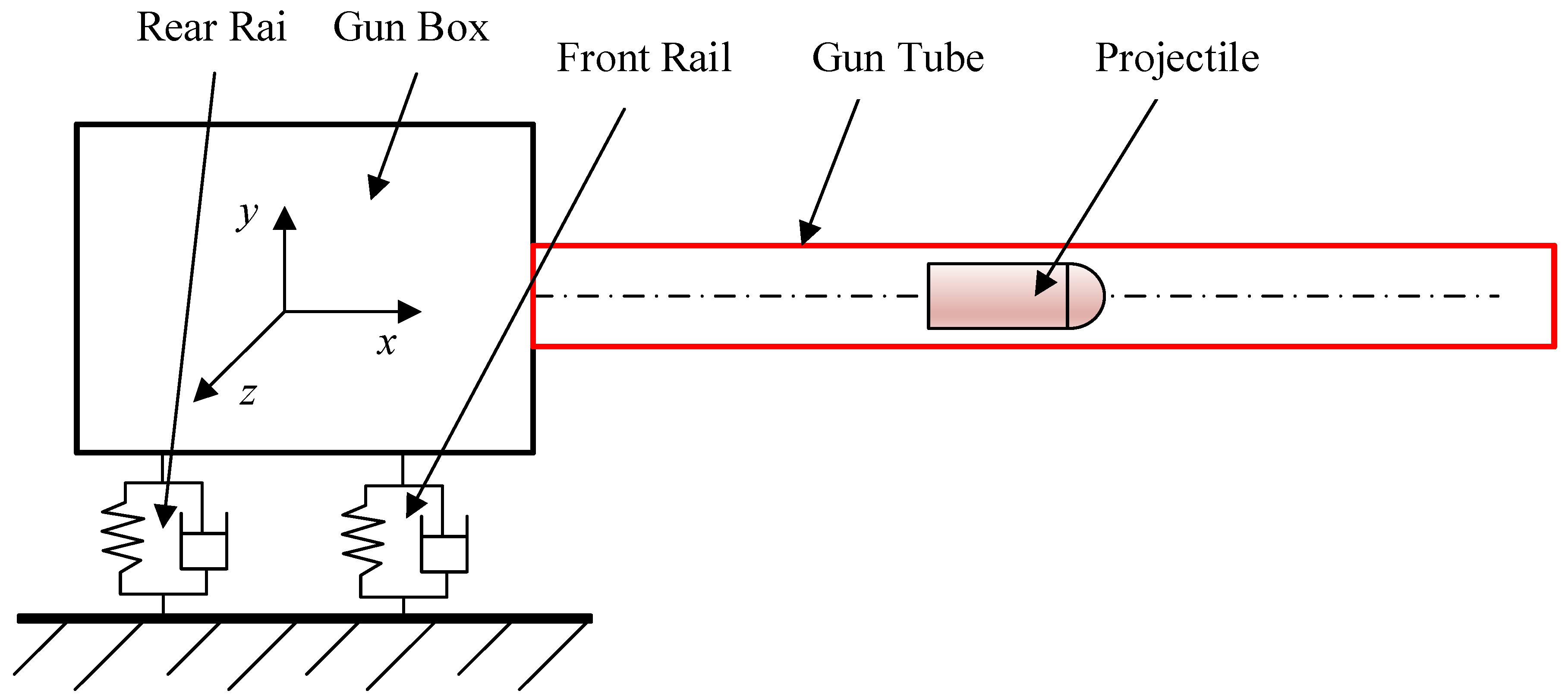
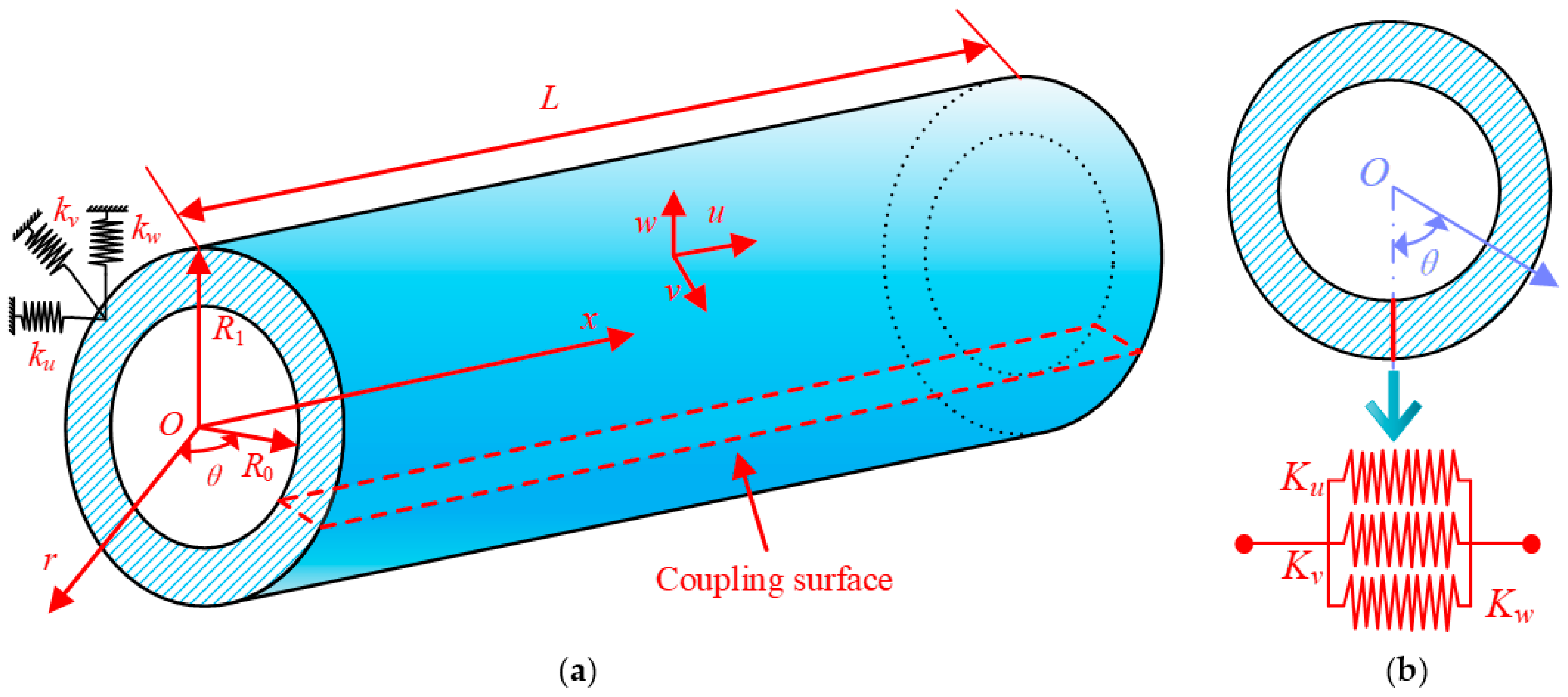
2.1. Model Description

The object of interest in the paper, as depicted in Figure 2a, is a 3D cylindrical shell characterized by an interior radius of R0, an outer radius of R1, and a length of L. The cylindrical coordinate system is used to define the shell in this paper, and the axes x, θ, and r depict the axial, circumferential, and radial directions, respectively. The corresponding displacement components of any point of the shell on the three axes are given by u, v, and w, respectively.
The spring constraint is applied at the end of the shell to represent the boundary conditions, containing three sets of linear springs k u i , k v i , and k w i , the superscript i = 0 means that the boundary spring is arranged at the x = 0 end of the cylindrical shell, and i = L means that it is arranged at the x = L end. Thus, all homogeneous boundary conditions can be obtained directly by setting suitable spring stiffness values. In addition, the kinematic and physical continuity conditions of a complete rotating shell should be satisfied at the circumference θ = 0 and θ = 2π. Therefore, coupling springs are set in these two surfaces in this paper. The three groups of face springs are denoted by Ku, Kv, and Kw (Figure 2b).

2.2. Energy Expressions

In this paper, the 3D shell theory is used to establish the cylindrical model, and the strains of the shell are defined as
ε x = u x , ε θ = v r θ + w r , ε r = w r γ θ r = w r θ + v r v r , γ x r = u r + w x , γ x θ = u r θ + v x
where the symbols ε x , ε θ , and ε r denote the normal strains, the symbols γ θ r , γ x r , and γ x θ are the shear strains.
The stresses can be defined by means of the generalized Hooke’s law:
σ x σ θ σ r τ θ r τ x r τ x θ = E 1 + μ 1 2 μ 1 μ μ μ 0 0 0 μ 1 μ μ 0 0 0 μ μ 1 μ 0 0 0 0 0 0 1 2 μ 0 0 0 0 0 0 1 2 μ 0 0 0 0 0 0 1 2 μ ε x ε θ ε r γ θ r γ x r γ x θ
where σ x , σ θ , and σ r are the normal stresses, τ θ r , τ x r , and τ x θ are the shear stresses. E and μ are Young’s modulus and Poisson’s ratio, respectively.
The strain energy of the shell is:
U = 1 2 Ω ε x σ x + ε θ σ θ + ε r σ r + γ θ r τ θ r + γ x r τ x r + γ x θ τ x θ r d θ d r d x
The strain energy function of the shell expressed in terms of displacements can be obtained by substituting Equations (1) and (2) into Equation (3):
U = E 2 ( 1 + μ ) ( 1 2 μ ) 0 L R 0 R 1 0 2 π ( 1 μ ) u x 2 + v r θ + w r 2 + w r 2 + 2 μ v r θ u x + u x w r + u x w r + v r θ w r + w r w r + 1 2 μ w r θ + v r v r 2 + u r + w x 2 + u r θ + v x 2 r d θ d r d x
The kinetic energy of cylindrical shells is expressed as:
T = ρ 2 0 L R 0 R 1 0 2 π u t 2 + v t 2 + w t 2 r d θ d r d x
where ρ denotes the density of cylindrical shells.
The potential energy of the spring on the two boundary end surfaces of 3D cylindrical shells is
U b = 1 2 R 0 R 1 0 2 π k u 0 u 2 + k v 0 v 2 + k w 0 w 2 x = 0 + k u L u 2 + k v L v 2 + k w L w 2 x = L r d θ d r
In this paper, to achieve the displacement continuity closure of the cylindrical shell, coupling springs are arranged on the two surfaces of θ = 0 and θ = 2π. The corresponding coupling potential energy is written as:
U c p = 1 2 R 0 R 1 0 L K u u θ = 0 u θ = 2 π 2 + K v v θ = 0 v θ = 2 π 2 + K w w θ = 0 w θ = 2 π 2 r d x d r

2.3. The Unified Formulation with Chebyshev Discretization

In the present study, the CUF is used to construct the displacement fields of the 3D cylindrical shell. The displacements u, v, and w in the cylindrical coordinate system are:
u x , θ , r = i = 1 Z 1 u i x , θ F i r = u 0 x , θ r 0 + u 1 x , θ r 1 + + u Z 1 x , θ r Z 1
v x , θ , r = i = 1 Z 1 v i x , θ F i r = v 0 x , θ r 0 + v 1 x , θ r 1 + + v Z 1 x , θ r Z 1
w x , θ , r = i = 1 Z 1 w i x , θ F i r = w 0 x , θ r 0 + w 1 x , θ r 1 + + w Z 1 x , θ r Z 1
where Fi is Taylor-like expansions, and Z denotes the number of terms of the expansion. ui, vi, and wi denote the displacement variables, which are approximated by Chebyshev polynomials of the first kind.
u i x , θ = m = 0 M 1 n = 0 N 1 A i m n cos m cos 1 x cos n cos 1 θ
v i x , θ = m = 0 M 1 n = 0 N 1 B i m n cos m cos 1 x cos n cos 1 θ
w i x , θ = m = 0 M 1 n = 0 N 1 C i m n cos m cos 1 x cos n cos 1 θ
in which M and N are the number of terms of Chebyshev polynomials. Aimn, Bimn, and Cimn represent the unknown coefficients of the expansion.
Considering that the radial direction of the cylindrical shell structure, also known as the thickness direction, has smaller dimensions than the other two directions, the Taylor series expansion is adopted for the radial direction in this paper. The advantage of doing so is obvious, which can significantly reduce the dimensionality of the displacement expansion. On the other hand, the use of CUF can also effectively avoid Poisson’s locking and does not require correction of the material stiffness coefficients.
It should be noted that the domain of definition of the radial direction of the cylindrical shell in this paper needs to be transformed from r R 0 , R 1 to r ¯ 0 , h (h = R1R0). Thus, the Taylor-like expansions can be rewritten as F i r ¯ , and the energy expressions of the cylindrical shell then get rewritten as:
U = E 2 ( 1 + μ ) ( 1 2 μ ) 0 L 0 h 0 2 π ( 1 μ ) ( u x ) 2 + ( w r ¯ ) 2 + ( v r ¯ + R 0 θ + w r ¯ + R 0 ) 2 +          2 μ v r ¯ + R 0 θ u x + u x w r ¯ + R 0 + u x w r ¯ + v r ¯ + R 0 θ w r ¯ + w r ¯ w r ¯ + R 0 + ( 1 2 μ ) w r ¯ + R 0 θ + v r ¯ v r ¯ + R 0 2 + u r ¯ + w x 2 + u r ¯ + R 0 θ + v x 2 r ¯ + R 0 d θ d r ¯ d x
T = ρ 2 0 L 0 h 0 2 π u t 2 + v t 2 + w t 2 r ¯ + R 0 d θ d r ¯ d x
U b = 1 2 0 h 0 2 π k u 0 u 2 + k v 0 v 2 + k w 0 w 2 x = 0 + k u L u 2 + k v L v 2 + k w L w 2 x = L r ¯ + R 0 d θ d r ¯
U c p = 1 2 0 h 0 L K u u θ = 0 u θ = 2 π 2 + K v v θ = 0 v θ = 2 π 2 + K w w θ = 0 w θ = 2 π 2 r ¯ + R 0 d x d r ¯

2.4. Solving Procedures

The Lagrange function of the cylindrical shell with elastic boundaries can be written as:
L = T U + U c p + U b
Substituting Equation (8) into Equation (14), and making the partial derivatives of the Lagrangian energy function regarding the unknown coefficients equal to zero:
L α = 0 α = A i m n , B i m n , C i m n
The following system characteristic equations can be summed up in matrix form:
M ω 2 K q = 0
where M and K represent the mass matrix and stiffness matrix of 3D cylindrical shells, respectively. q = A i m n B i m n C i m n T is the vector of unknown coefficients. The detailed expressions of the mass and stiffness matrix are
M = M u u M u v M u w M v u M v v M v w M w u M w v M w w
K = K u u K u v K u w K v u K v v K v w K w u K w v K w w
where the dimensions of the submatrix Mij and Kij (i, j = u, v, w) are M × N × Z. By using the eigenvalue function ‘eigs’ in MATLAB, Equation (16) can be solved quickly to obtain the frequency and model characteristics of the shells. The detailed expressions of stiffness matrix K and mass matrix M can be found in Appendix A.

3. Results and Discussion

In this section, the free vibration characteristics of 3D cylindrical shells are investigated. Based on the theoretical formulations presented in the preceding section, numerous vibration results for cylindrical shells with different boundary conditions are presented, which prove the correctness, efficiency, and reliability of the solution proposed in this paper. Firstly, we will determine the stiffness values of the coupling spring and the boundary spring in the present method for the next calculation, then the convergence and efficiency of the present scheme are studied. Next, some computational results of the current approach are given and the accuracy of the model in this paper is checked by comparing it with the results in the open literature, including the modal of shells with various boundary conditions and their combinations. Finally, parameter studies for cylindrical shells with different geometric features are investigated.

3.1. Spring Parameters and Convergence Study

In this paper, the general artificial boundary spring technology is implemented to simulate the boundary forces and displacements of each end of the shells. Therefore, by setting different stiffness parameters for three groups of boundary surface springs, arbitrary boundary conditions of the 3D cylindrical shell can be obtained. In the current study, a clamped end of the shell can be sassily achieved by setting the stiffness of all boundary surface springs to a large value of 1014, while the free boundary conditions are achieved by setting the stiffness value to 0. The symbols C, S, F, and E1 are used to represent the clamped, simply supported, free, and elastically boundary conditions, respectively. The corresponding spring parameters are displayed in Table 2. Thus, the boundary conditions at both ends of the shells can be represented by two letters. For example, CF means that the 3D shell is fully constrained at surface x = 0 and free at surface x = L.
The CUF utilized in the current solution holds infinite expansion potential in theory. Nevertheless, truncation becomes necessary in practical calculations to satisfy the computational efficiency requirements. Subsequently, the task at hand involves identifying the suitable truncation numbers M, N, and Z for the displacement expansions in the axial, circumferential, and radial directions, respectively. Table 3 outlines the investigation of the first six non-dimensional frequencies of a 3D cylindrical shell with free edges, considering various truncation numbers. The results provide valuable insights into the optimal truncation numbers required for accurate and efficient calculations of the vibrational behavior of cylindrical shells. The dimensionless frequency parameter is set as Ω = ω R 1 ρ / E / 2 + 2 μ . The geometric and material constants of the shell in Table 3 are inner radius R0 =1, outer radius R1 = 1.5, length L = 4, and Poisson’s ratio μ = 0.3. This paper, in particular, does not take into account the rigid body modes at completely free boundaries. Nonetheless, the results showcased in Table 3 demonstrate the excellent convergence of the current method, with the dimensionless frequency ultimately converging to a constant value when the dimensions of M and N surpass 12. Additionally, when both M and N are set to 18, the maximum disparity observed between the axial truncation number Z taken as 3 and 4 is merely 0.0573%, thereby affirming the robustness and reliability of the proposed approach. Table 4 lists the natural frequencies of a cylindrical shell with CF boundaries. The geometric parameters of the shell are set as R0 = 0.015, R1 = 0.03, and L = 2. As demonstrated in Table 4, it can be observed that with the increase in truncation numbers M and N, there is a corresponding decrease in the error between their natural frequency results. Furthermore, this error does not exceed 0.02%. It is important to note that due to the relatively thin thickness of the cylindrical shell under consideration, the axial truncation number Z has a negligible effect on the results. In light of these findings, the truncation numbers for the present work have been uniformly selected as M = N = 16 and Z = 4 for all subsequent calculations.

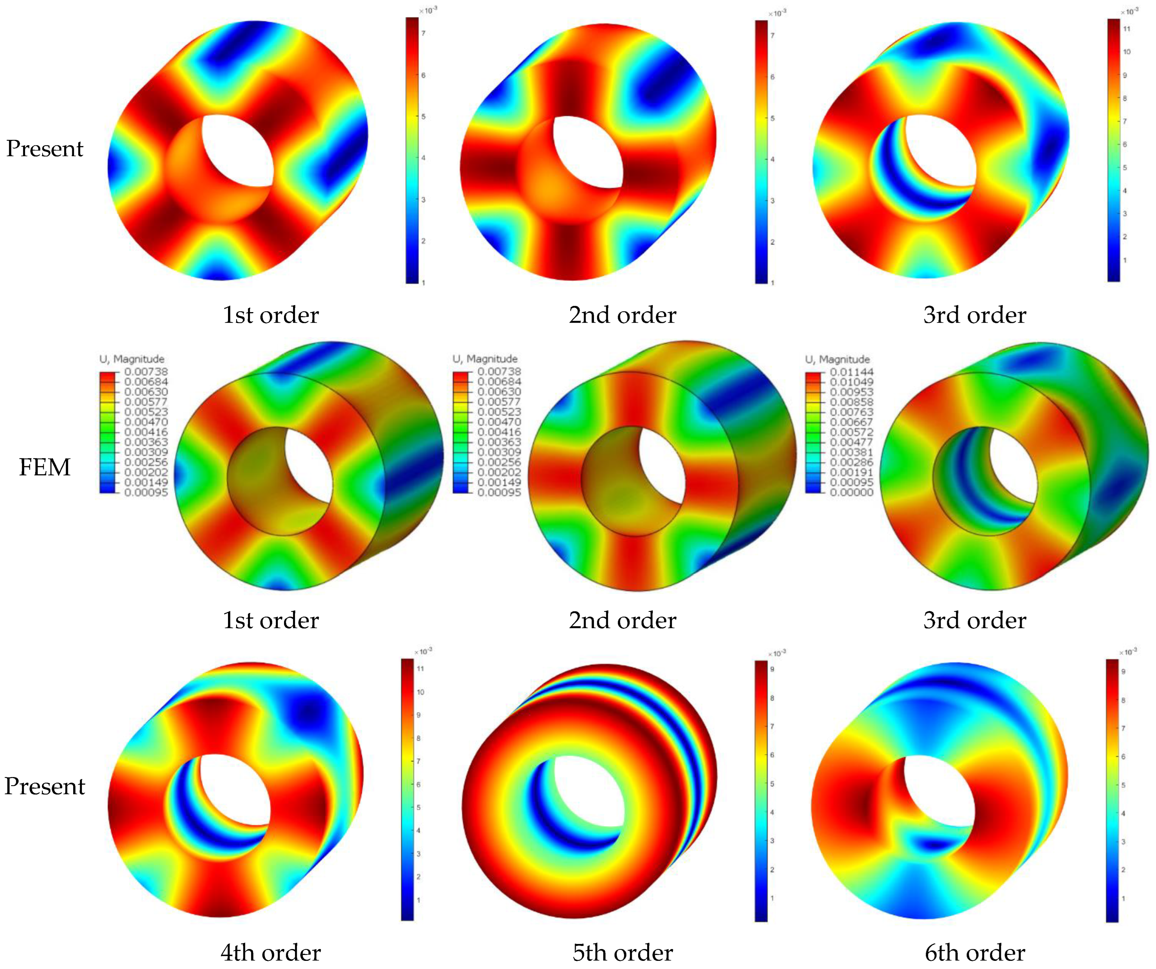
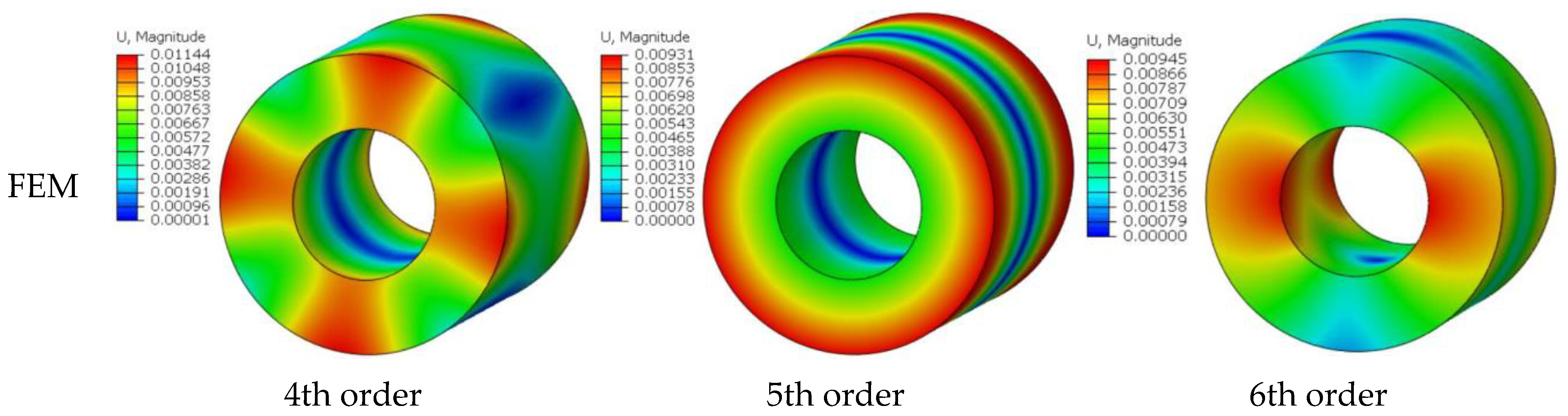
3.2. Results Validation

In this section, the accuracy and generality of the proposed solution are rigorously evaluated through a comparative analysis of the calculation results presented in this paper with those obtained from other relevant literature and finite element analyses. The results of this comparison serve to confirm the validity and robustness of the proposed solution. Table 5 presents the non-dimensional frequency parameters Ω = ω R 1 ρ / E for an FF solid cylinder, which are compared with the results from existing literature. The geometric parameter of the cylinder is L/R1 = 4. As evidenced by the data presented in the table, it can be observed that there is a high degree of consistency between the current results and the reference data. It is important to note that the reference literature employed the Rayleigh—Ritz method, wherein the cylindrical circumferential displacements were characterized in terms of circumferential wave numbers, and the frequency does not increase with wave numbers.
Table 6 shows the dimensionless frequencies Ω = ω R 1 ρ / E / 2 + 2 μ determined by the various methods in order to further contrast the differences between the approach used in this paper and the modeling approach that takes the cylindrical shell’s circumferential symmetry into account. The geometric and material parameters of the shell are: inner–outer ratio R0/R1 = 0.5, length–radius ratio L/R1 = 2, and μ = 0.3. The total number of meshes for the FEM model is 124,000, and the mesh type is a 3D hexahedral mesh. As indicated by the data presented in the table, it can be observed that the current method yields highly accurate calculation results when compared with the literature method. Furthermore, the frequencies of the cylindrical shell can be determined in a sequential manner. When compared with the calculation results obtained from FEM, it is evident that the method proposed in this paper exhibits a high degree of consistency. In particular, the first twenty orders of modalities can be accurately calculated using this method. The corresponding mode shapes are drawn in Figure 3. From the comparison of modal pictures, it can be seen that the current solution conforms well with the FEM, and all the vibration patterns can be effectively represented. It should be particularly noted that the fifth-order mode is an asymmetric mode.
Table 7 presents the frequency parameters Ω = ω h / π ρ / E / 2 + 2 μ for the cylindrical shell under SS boundary conditions. Three length—radius ratios L/R are listed in the table, and the geometric parameters of the shell are h/R = 0.1, in which R indicates the radius of the middle surface of the shell. Based on the results presented, it can be concluded that there is a high degree of agreement between the current results and those reported in the reference work. It is hypothesized that the primary source of error between the two sets of results may be attributed to the differences in the displacement admissible functions selected by the respective methods.
Next, we study cylindrical shells with much larger axial dimensions than radial dimensions; typical structures of this type include pipelines, artillery, rockets, etc. Table 8 lists the first 8 frequency parameters Ω = ω L ρ / E / ( 2 + 2 μ ) for a cylindrical shell with various boundary conditions, the results in the table are obtained by the present method and FEM. The geometric parameters of the shell are the same as the shells in Table 4. From the results of this table, the precision of the current method is demonstrated once more. The maximum difference of the calculation of the method in this paper does not exceed 1.163% compared with the results of FEM calculation. The primary reason for the observed differences between the results obtained using the current method and those obtained using finite element analyses can be attributed to the manner in which the elastic boundary is imposed. In the case of FEM, the elastic boundary is imposed through discrete mesh nodes. In contrast, the current method directly imposes the elastic boundary on the entire boundary surface. The results of this comparison serve to demonstrate the effectiveness of the current method in accurately modeling the elastic boundary. Figure 4 presents some modal diagraphs of the cylindrical shell with CF boundary conditions in Table 8. The mode shapes of this type of cylindrical shell are similar to that of beam structures, which can be seen from the first 3rd-order modal diagram. Meanwhile, the current method can accurately simulate the radial asymmetric mode of cylindrical shells. The accuracy of the present solution is again demonstrated by the modal comparison.

3.3. Numerical Study

Following the successful verification of the accuracy of the current method in modeling the free vibration of 3D cylindrical shells under a range of boundary conditions and geometric parameters, this subsection will present new vibration results obtained using this method for 3D cylindrical shells. The first 9 dimensionless frequency parameters Ω = ω R 1 ρ / E / ( 2 + 2 μ ) of the cylindrical shell with different boundary conditions and lengths are listed in Table 9. The material and geometric parameters of the shell in this table are set as E = 206 GPa, μ = 0.3, ρ = 7850 kg/m3, R0 = 0.1, and R1 = 0.3. The data presented in the table reveal a decreasing trend in the frequency parameter of the cylindrical shell as the length is increased. This phenomenon can be attributed to the decrease in stiffness that is observed in longer shells, which renders them more susceptible to vibrations. Furthermore, variations in the boundary conditions and length of the shell tend to alter the manifestation of the shell’s symmetric modes, thereby affecting its vibrational characteristics.
Table 10 presents the first 8 dimensionless frequency parameters Ω = ω L ρ / E / ( 2 + 2 μ ) of the cylindrical shell with different boundary conditions and radius of the middle surface. The material and geometric parameters of the shell in this table are set as E = 206 GPa, μ = 0.3, ρ = 7850 kg/m3, h = 0.1, R0 = R − h/2, R1 = R + h/2, and L = 2. As indicated by the data presented, it can be observed that the frequency parameter of the shell exhibits a decreasing trend with increasing radius. This phenomenon can be attributed to the fact that, as the radius of the shell increases, its mass also increases. It is important to note that changes in the radius of the cylindrical shell do not appear to have a significant impact on the distribution of its symmetric modes. Furthermore, as evidenced by the data presented in Table 9 and Table 10, it can be seen that the frequency results obtained for both elastic and free boundaries are largely consistent. This suggests that the stiffness of the springs has not had a significant impact on the structure.
Next, we will conduct a more detailed investigation into the effects of both thickness and length on the frequency characteristics of the cylindrical shell. Figure 5 shows the changes in the dimensionless frequency parameters Ω = ω ρ / E of the cylindrical shell with different thicknesses h and lengths L. The material and geometric parameters of the shell in this table are set as E = 206 GPa, μ = 0.3, ρ = 7850 kg/m3, R = 1, R0 = Rh/2, and R1 = R + h/2. As depicted in Figure 5, it can be observed that the frequency of the cylindrical shell structure exhibits an increasing trend with increasing thickness and a decreasing trend with increasing length. Furthermore, it is important to note that, as the length of the shell increases, the rate at which its frequency decreases with increasing thickness becomes slower.

4. Conclusions

The 3D vibration characteristics of the cylindrical shell with generally restrained ends are studied in this paper. A new 3D vibration analysis model applicable to the cylindrical shell is established by combining the CUF and Chebyshev polynomials. The elastic constraint boundaries at both ends of the cylindrical shell were simulated using the penalty function technique during the modeling process. The frequency and modal properties of cylindrical shells with various boundary conditions and geometrical parameters are calculated and compared to results from related literature and FEM. The conclusions of the present study can be drawn as follows:
(1)
The CUF model used in this paper is extended with Chebyshev polynomials and Taylor series for displacements in the axial, circumferential, and radial directions of the cylindrical shell, which effectively reduces the 3D model’s dimensionality.
(2)
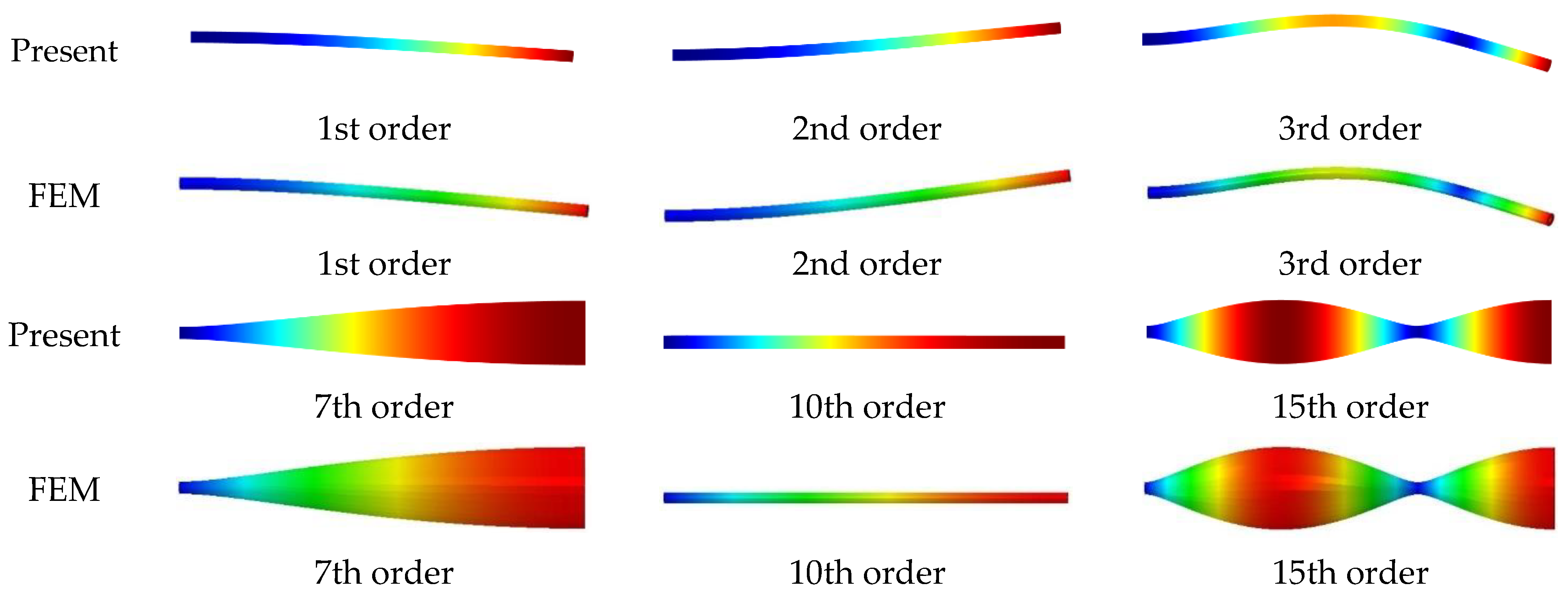
The model presented in this study can be used to investigate the free vibration features of elastically constrained, 3D cylindrical shells. The model has good convergence, according to the results of the pertinent calculations. Additionally, the model’s great computational correctness and universality can be demonstrated by comparison with relevant literature and finite element results.
(3)
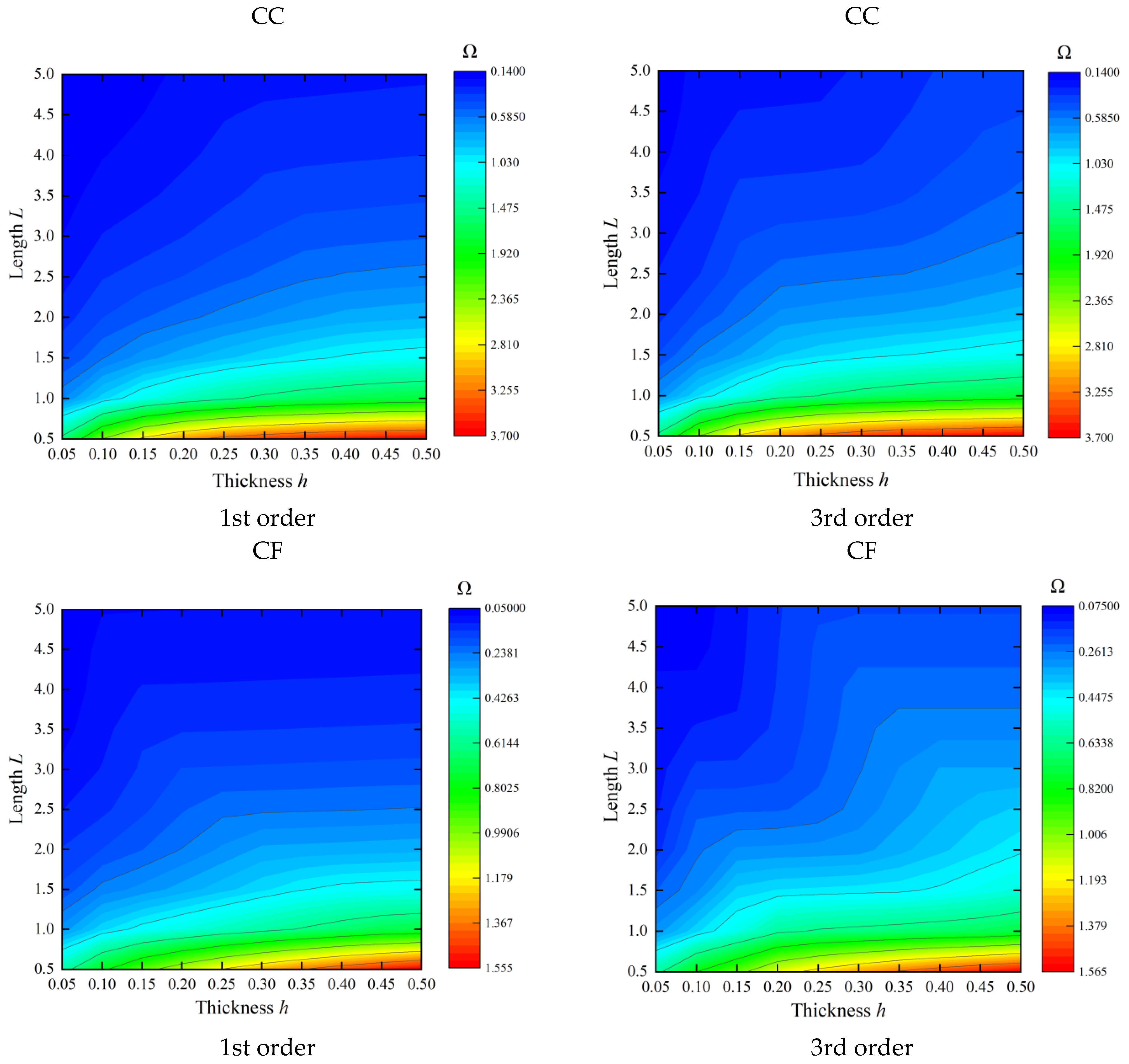
The frequency parameter of the shell decreases with increasing length, since the longer the shell, the lower the stiffness, thus the higher the proneness to vibration. The frequency parameter of the shell decreases with increasing radius, mainly because the mass of the shell increases with increasing radius. The frequency of the cylindrical shell structure increases with thickness, and the longer the length, the slower the decreasing trend of its frequency with the increase of the thickness of shells.
(4)
The main drawback of the study in this paper is the inability to analyze the cylindrical shell structure with variable thickness characteristics, and the strong nonlinear characteristics are not considered.
(5)
The research in this paper can provide support for the optimal design of cylindrical shell-like gun tube structures and dynamics performance prediction in the future, and can be further extended to the vibration characteristics analysis of composite cylindrical shells.

Author Contributions

Methodology, W.L.; Software, W.L. and C.L.; Investigation, W.L., T.L. and C.L.; Writing—original draft, W.L.; Writing—review & editing, T.L. and Q.W.; Visualization, C.L.; Supervision, Q.W.; Funding acquisition, T.L. All authors have read and agreed to the published version of the manuscript.

Funding

The authors gratefully acknowledge the financial support from the Fundamental Research Funds of the Central Universities of Central South University (Grant Nos. 1053320200125).

Institutional Review Board Statement

Not applicable.

Informed Consent Statement

Not applicable.

Data Availability Statement

Data sharing not applicable.

Conflicts of Interest

The authors declare no conflict of interest.

Appendix A. Detailed Expressions for the Mass Matrix M and Stiffness Matrix K

The detailed expressions of the mass matrix M and stiffness matrix K in Equations (17) and (18) are given as follows.
Μ u u = Μ v v = Μ w w = ρ G x G θ G r
Μ u v = Μ v u = Μ u w = Μ w u = Μ v w = Μ w v = 0
K u u = E 1 μ 1 + μ 1 2 μ G x 1 G θ G r + E 2 1 + μ G x G θ G r 1 + E 2 1 + μ G x G θ 1 G r + k u 0 G x = 1 G θ G r + k u L G x = L G θ G r + K u G x G θ = 0 G r + G x G θ = 2 π G r 2 G x G θ = 0 , θ = 2 π G r
K u v = K v u = E μ 1 + μ 1 2 μ G x 11 G θ 11 G r + E 2 1 + μ G θ 11 G x 11 G r
K u w = K w u = E μ 1 + μ 1 2 μ G x 11 G θ G r + E μ 1 + μ 1 2 μ G x 11 G θ G r 11 + E 2 1 + μ G x 11 G θ G r 11
K v v = E ( 1 μ ) ( 1 + μ ) ( 1 2 μ ) G x G θ 1 G r + E 2 ( 1 + μ ) G x G θ G r + E 2 ( 1 + μ ) G x 1 G θ G r + E 2 ( 1 + μ ) G x G θ G r 1 E ( 1 + μ ) G x G θ G r 11 + k v 0 G x = 1 G θ G r + k v L G x = L G θ G r + K v G x G θ = 0 G r + G x G θ = 2 π G r 2 G x G θ = 0 , θ = 2 π G r
K w v = K w v = E ( 1 μ ) ( 1 + μ ) ( 1 2 μ ) G x G θ 11 G r + E μ ( 1 + μ ) ( 1 2 μ ) G x G θ 11 G r 11 + E 2 ( 1 + μ ) G x G θ 11 G r 11 E 2 ( 1 + μ ) G x G θ 11 G r
K w w = E ( 1 μ ) ( 1 + μ ) ( 1 2 μ ) G x G θ G r + 2 E μ ( 1 + μ ) ( 1 2 μ ) G x G θ G r 11 + E ( 1 μ ) ( 1 + μ ) ( 1 2 μ ) G x G θ G r 1 + E 2 ( 1 + μ ) G x G θ 1 G r + E ( 1 + μ ) G x 1 G θ G r + k w 0 G x = 1 G θ G r + k w L G x = L G θ G r + K w G x G θ = 0 G r + G x G θ = 2 π G r 2 G x G θ = 0 , θ = 2 π G r
where
G x = 0 L m = 1 M 1 m = 1 M 1 cos m cos 1 x cos m cos 1 x d x
G θ = 0 2 π n = 1 N 1 n = 1 N 1 cos n cos 1 θ cos n cos 1 θ d θ
G r = 0 h i = 1 Z 1 i = 1 Z 1 r ¯ i r ¯ i r ¯ + R 0 d r ¯
G x 1 = 0 L m = 1 M 1 m = 1 M 1 d cos m cos 1 x d x d cos m cos 1 x d x d x
G θ 1 = 0 2 π n = 1 N 1 n = 1 N 1 d cos n cos 1 θ d θ d cos n cos 1 θ d θ d θ
G r 1 = 0 h i = 1 Z 1 i = 1 Z 1 d r ¯ d r ¯ i d r ¯ i d r ¯ r ¯ + R 0 d r ¯
G x 11 = 0 L m = 1 M 1 m = 1 M 1 d cos m cos 1 x d x cos m cos 1 x d x
G θ 11 = 0 2 π n = 1 N 1 n = 1 N 1 d cos n cos 1 θ d θ cos n cos 1 θ d θ
G r 11 = 0 h i = 1 Z 1 i = 1 Z 1 d r ¯ d r ¯ i r ¯ i r ¯ + R 0 d r ¯

References

  1. Zhao, Y.; Zhou, Q.; Yue, P. Research on Vibration Characteristics of Gun Barrel Based on Contact Model. AIP Conf. Proc. 2017, 1829, 020017. [Google Scholar]
  2. Koç, M.A. Development of an Intelligent Software Based on Adaptive Neural-Fuzzy Inference Systems for Predicting Muzzle Vibration of a Gun Barrel. Arab. J. Sci. Eng. 2022, 47, 8829–8846. [Google Scholar] [CrossRef]
  3. Liew, K.M.; Hung, K.C. Three-dimensional vibratory characteristics of solid cylinders and some remarks on simplified beam theories. Int. J. Solids Struct. 1995, 32, 3499–3513. [Google Scholar] [CrossRef]
  4. Loy, C.T.; Lam, K.Y. Vibration of thick cylindrical shells on the basis of three-dimensional theory of elasticity. J. Sound Vib. 1999, 226, 719–737. [Google Scholar] [CrossRef]
  5. Zhou, D.; Cheung, Y.K.; Lo, S.H.; Au, F.T.K. 3D vibration analysis of solid and hollow circular cylinders via Chebyshev–Ritz method. Comput. Methods Appl. Mech. Eng. 2003, 192, 1575–1589. [Google Scholar] [CrossRef]
  6. Mofakhami, M.R.; Toudeshky, H.H.; Hashemi, S.H. Finite cylinder vibrations with different end boundary conditions. J. Sound Vib. 2006, 297, 293–314. [Google Scholar] [CrossRef]
  7. Khalili, S.M.R.; Davar, A.; Malekzadeh Fard, K. Free vibration analysis of homogeneous isotropic circular cylindrical shells based on a new three-dimensional refined higher-order theory. Int. J. Mech. Sci. 2012, 56, 1–25. [Google Scholar] [CrossRef]
  8. Malekzadeh, P.; Farid, M.; Zahedinejad, P.; Karami, G. Three-dimensional free vibration analysis of thick cylindrical shells resting on two-parameter elastic supports. J. Sound Vib. 2008, 313, 655–675. [Google Scholar] [CrossRef]
  9. Ye, T.; Jin, G.; Shi, S.; Ma, X. Three-dimensional free vibration analysis of thick cylindrical shells with general end conditions and resting on elastic foundations. Int. J. Mech. Sci. 2014, 84, 120–137. [Google Scholar] [CrossRef]
  10. Atashipour, S.R.; Mohammadi, Z.; Folkow, P.D. A direct approach for three-dimensional elasto-static and elasto-dynamic solutions in curvilinear cylindrical coordinates with application to classical cylinder problems. Eur. J. Mech.—A/Solids 2022, 95, 104646. [Google Scholar] [CrossRef]
  11. Xiang, S.; Bi, Z.-y.; Jiang, S.-x.; Jin, Y.-x.; Yang, M.-s. Thin plate spline radial basis function for the free vibration analysis of laminated composite shells. Compos. Struct. 2011, 93, 611–615. [Google Scholar] [CrossRef]
  12. Tornabene, F.; Fantuzzi, N.; Bacciocchi, M. The GDQ method for the free vibration analysis of arbitrarily shaped laminated composite shells using a NURBS-based isogeometric approach. Compos. Struct. 2016, 154, 190–218. [Google Scholar] [CrossRef]
  13. Wang, Q.; Cui, X.; Qin, B.; Liang, Q.; Tang, J. A semi-analytical method for vibration analysis of functionally graded (FG) sandwich doubly-curved panels and shells of revolution. Int. J. Mech. Sci. 2017, 134 (Suppl. C), 479–499. [Google Scholar] [CrossRef]
  14. Fan, J.; Huang, J.; Juxiang, Z.; Jie, Z. The Walsh series method for free vibration analysis of functionally graded cylindrical shells. Compos. Struct. 2018, 206, 853–864. [Google Scholar] [CrossRef]
  15. Chen, Z.; Wang, A.; Qin, B.; Wang, Q.; Zhong, R. Investigation on free vibration and transient response of functionally graded graphene platelets reinforced cylindrical shell resting on elastic foundation. Eur. Phys. J. Plus 2020, 135, 582. [Google Scholar] [CrossRef]
  16. Liu, T.; Wang, A.; Wang, Q.; Qin, B. Wave based method for free vibration characteristics of functionally graded cylindrical shells with arbitrary boundary conditions. Thin-Walled Struct. 2020, 148, 106580. [Google Scholar] [CrossRef]
  17. Chenchen, G.; Liu, T.; Wang, Q.; Bin, Q.; Shao, W.; Wang, A. Spectral-Tchebychev technique for the free vibration analysis of composite laminated stepped and stiffened cylindrical shells with arbitrary boundary conditions. Compos. Struct. 2021, 272, 114193. [Google Scholar] [CrossRef]
  18. Qin, Z.; Chu, F.; Zu, J. Free vibrations of cylindrical shells with arbitrary boundary conditions: A comparison study. Int. J. Mech. Sci. 2017, 133, 91–99. [Google Scholar] [CrossRef]
  19. Rahimi, A.; Alibeigloo, A.; Safarpour, M. Three-dimensional static and free vibration analysis of graphene platelet–reinforced porous composite cylindrical shell. J. Vib. Control 2020, 26, 1627–1645. [Google Scholar] [CrossRef]
  20. Zheng, D.; Du, J.; Liu, Y. Vibration characteristics analysis of an elastically restrained cylindrical shell with arbitrary thickness variation. Thin-Walled Struct. 2021, 165, 107930. [Google Scholar] [CrossRef]
  21. Su, Z.; Jin, G.; Ye, T. Three-dimensional vibration analysis of thick functionally graded conical, cylindrical shell and annular plate structures with arbitrary elastic restraints. Compos. Struct. 2014, 118, 432–447. [Google Scholar] [CrossRef]
  22. Qin, B.; Wang, Q.; Zhong, R.; Zhao, X.; Shuai, C. A three-dimensional solution for free vibration of FGP-GPLRC cylindrical shells resting on elastic foundations: A comparative and parametric study. Int. J. Mech. Sci. 2020, 187, 105896. [Google Scholar] [CrossRef]
  23. Cuong-Le, T.; Nguyen, K.D.; Nguyen-Trong, N.; Khatir, S.; Nguyen-Xuan, H.; Abdel-Wahab, M. A three-dimensional solution for free vibration and buckling of annular plate, conical, cylinder and cylindrical shell of FG porous-cellular materials using IGA. Compos. Struct. 2021, 259, 113216. [Google Scholar] [CrossRef]
  24. Tong, B.; Li, Y.; Zhu, X.; Zhang, Y. Three-dimensional vibration analysis of arbitrary angle-ply laminated cylindrical shells using differential quadrature method. Appl. Acoust. 2019, 146, 390–397. [Google Scholar] [CrossRef]
  25. Carrera, E.; Brischetto, S.; Nali, P. Plates and Shells for Smart Structures: Classical and Advanced Theories for Modeling and Analysis; John Wiley & Sons: Hoboken, NJ, USA, 2011; Volume 36. [Google Scholar]
  26. Petrolo, M.; Carrera, E.; Cinefra, M.; Zappino, E. Finite Element Analysis of Structures through Unified Formulation; John Wiley & Sons: Hoboken, NJ, USA, 2014. [Google Scholar]
  27. Carrera, E.; Giunta, G.; Petrolo, M. Beam Structures: Classical and Advanced Theories; John Wiley & Sons: Hoboken, NJ, USA, 2011. [Google Scholar]
  28. Carrera, E.; Miglioretti, F.; Petrolo, M. Accuracy of refined finite elements for laminated plate analysis. Compos. Struct. 2011, 93, 1311–1327. [Google Scholar] [CrossRef]
  29. Carrera, E.; Elishakoff, I.; Petrolo, M. Who needs refined structural theories? Compos. Struct. 2021, 264, 113671. [Google Scholar] [CrossRef]
  30. Carrera, E.; Zozulya, V.V. Carrera unified formulation (CUF) for the shells of revolution. Numerical evaluation. Mech. Adv. Mater. Struct. 2022, 1–23. [Google Scholar] [CrossRef]
  31. Carrera, E.; Zozulya, V.V. Carrera unified formulation (CUF) for shells of revolution. I. Higher-order theory. Acta Mech. 2022, 234, 109–136. [Google Scholar] [CrossRef]
  32. Carrera, E.; Zozulya, V.V. Carrera unified formulation (CUF) for the shells of revolution. II. Navier close form solutions. Acta Mech. 2022, 234, 137–161. [Google Scholar] [CrossRef]
  33. Armenàkas, A.E.; Gazis, D.C.; Herrmann, G. Free Vibrations of Circular Cylindrical Shells; Elsevier: Amsterdam, The Netherlands, 2016. [Google Scholar]
Figure 1. The physical model of an automatic gun.
Materials 16 03345 g001
Figure 2. Schematic diagram of a 3D cylindrical shell: (a) the whole shell; (b) the coupling surface.
Materials 16 03345 g002
Figure 3. The comparison of the first 6 mode shapes for an FF cylindrical shell between the present method and FEM.
Materials 16 03345 g003aMaterials 16 03345 g003b
Figure 4. The modal digraph of a CF cylindrical shell.
Materials 16 03345 g004
Figure 5. The variations of the frequency parameters Ω = ω ρ / E for cylindrical shells versus varying thickness and length.
Materials 16 03345 g005
Table 1. Recent studies on the vibration of cylindrical shell structures.
AuthorsMaterialsElastic TheoryMethod
Xiang et al. [11]Laminated compositesFirst-order shear deformation theoryMeshless global collocation method
Tornabene et al. [12]Higher-order shear deformation theoryGeneralized Differential Quadrature method
Wang et al. [13]Functionally graded sandwich materialsFirst-order shear deformation theoryFourier series expression method
Fan et al. [14]Functionally graded materialsWalsh series method
Chen et al. [15]Functionally graded graphene platelets-reinforced materialsChebyshev–Lagrangian approach
Liu et al. [16]Functionally graded materialsWave-based method
Guo et al. [17]Laminated compositesSpectral-Tchebychev technique
Qin et al. [18]Isotropic materialsSanders shell theoryRayleigh—Ritz method
Rahimi et al. [19]Graphene platelet-reinforced porous composites3D elastic theoryDifferential quadrature method
Zheng et al. [20]Isotropic materialsDonnell—Mushtari shell theoryModified Fourier series method
Table 2. Spring parameters for different boundary restraints.
Boundary ConditionsSpring Parameters
kukvkw
C101410141014
S010141014
F000
E1104104104
Table 3. The convergence of the first 6 dimensionless frequency parameters Ω = ω R 1 ρ / E / 2 + 2 μ for the FF cylindrical shell.
ZM × NModes
123456
38 × 80.65820.68580.71630.72071.17801.2040
10 × 100.58140.58280.64400.64451.17811.1787
12 × 120.57820.57820.64150.64161.17811.1789
14 × 140.57820.57820.64160.64171.17811.1792
16 × 160.57820.57820.64170.64171.17811.1792
18 × 180.57820.57820.64170.64171.17811.1792
48 × 80.65760.68550.71580.72031.17801.2036
10 × 100.58100.58240.64370.64411.17811.1783
12 × 120.57790.57790.64120.64121.17811.1785
14 × 140.57790.57790.64130.64131.17811.1788
16 × 160.57790.57790.64140.64141.17811.1788
18 × 180.57790.57790.64140.64141.17811.1788
Table 4. The convergence of the first 6 natural frequencies for the CF cylindrical shell.
ZM × NModes
123456
38 × 866.28499.632141.104159.373218.621251.441
10 × 1012.36813.42275.15175.310208.602208.671
12 × 1212.03312.03475.02275.035208.373208.474
14 × 1412.02712.02774.98975.002208.291208.381
16 × 1612.02412.02474.97074.982208.247208.327
18 × 1812.02212.02274.96074.971208.226208.297
48 × 866.11099.516140.831159.131218.567251.287
10 × 1012.36513.41575.15075.308208.599208.668
12 × 1212.03312.03475.02175.035208.370208.472
14 × 1412.02712.02774.98875.001208.288208.378
16 × 1612.02412.02474.96974.981208.244208.324
18 × 1812.02212.02274.95974.970208.223208.295
Table 5. Comparison of the first 9 frequency parameters Ω = ω R 1 ρ / E for an FF solid cylinder.
MethodMode Number
123456789
Liew [3]0.95940.95940.97421.54671.77511.77511.94832.59382.5938
Ye [9]0.95950.95950.97421.54671.77511.77511.94832.59382.5938
Present0.9595 0.9595 0.9742 1.5467 1.7751 1.7751 1.9483 2.5939 2.5939
Diff L0.01%0.01%000000.004%0.004%
Diff Y00000000.004%0.004%
Table 6. Comparison of the frequency parameters Ω = ω R 1 ρ / E / ( 2 + 2 μ ) for an FF cylindrical shell.
Mode NumberMethod
PresentFEMYe [9]Zhou [5]
10.97030.96860.97000.9700
20.97030.9686
31.04541.04291.04511.0451
41.04541.0429
51.57081.5695
61.60411.60361.60411.6041
71.60411.6036
81.89321.88911.89321.8932
91.89321.8891
101.93541.92881.93511.9351
111.93541.9288
122.04242.0413
132.15132.1489
142.28832.2834
152.28852.2835
162.30472.2969
172.34882.3421
182.34902.3421
192.48072.47642.48072.4807
202.48072.4764
Table 7. Comparison of the frequency parameters Ω = ω h / π ρ / E / ( 2 + 2 μ ) for the cylinder shell with SS boundaries.
L/RMethodMode Number
12345678
2Ye [9]0.01814 0.01906 0.03100
Ref. [33]0.01814 0.01907 0.03100
Ref. [7]0.01814 0.01906 0.03100
Present0.018140.018140.019070.019070.026270.026400.031000.03100
1Ye [9] 0.03642 0.03971
Ref. [33] 0.03643 0.03927
Ref. [7] 0.03641 0.03969
Present0.031840.031840.036430.036440.039720.039720.040360.04066
0.5Ye [9] 0.07616 0.07681
Ref. [33] 0.07618 0.07684
Ref. [7] 0.07607 0.07675
Present0.031840.031840.063680.063680.076140.076170.076170.07684
Table 8. Comparison of the first 8 frequency parameters Ω = ω L ρ / E / ( 2 + 2 μ ) for the cylindrical shell with different boundary conditions.
B.C.MethodMode Number
12345678
FFFEM0.29870.29920.81800.81931.58831.59062.59272.5964
Present0.30150.30150.82530.82551.60211.60272.61442.6160
Error0.908%0.761%0.894%0.761%0.870%0.760%0.837%0.758%
CFFEM0.04710.04720.29380.29430.81640.81771.55211.5825
Present0.04760.04760.29650.29660.82370.82401.55991.5959
Error0.940%0.780%0.917%0.781%0.889%0.776%0.505%0.849%
CCFEM0.29810.29860.81420.81541.57681.57912.56802.5715
Present0.30090.30100.82150.82191.59001.59142.58822.5916
Error0.923%0.796%0.894%0.800%0.834%0.781%0.788%0.782%
E1E1FEM0.29900.29940.81830.81951.58851.59082.59302.5966
Present0.30150.30150.82530.82551.60191.60272.61382.6160
Error0.850%0.699%0.861%0.734%0.842%0.745%0.805%0.749%
CE1FEM0.04720.04730.29400.29440.81660.81781.55211.5826
Present0.04770.04770.29660.29660.82370.82401.55991.5959
Error1.163%1.004%0.886%0.747%0.875%0.763%0.505%0.841%
Table 9. The first 8 frequency parameters Ω = ω R 1 ρ / E / ( 2 + 2 μ ) for a cylindrical shell with various boundary conditions and lengths.
B.C.LMode Number
12345678
FF0.51.41111.41141.44711.44781.88481.94711.94752.3868
10.94241.01161.01161.45021.45071.45471.45541.4753
20.34680.34680.47120.74310.74310.75540.94241.1672
CF0.50.64460.64470.94231.52731.52781.53691.68561.6858
10.22240.22240.47120.76700.79430.79441.41351.4589
20.06380.06380.23560.30800.30800.38210.69190.6920
CC0.51.68501.68531.88442.20742.20773.05423.08053.1789
10.75250.75260.94231.48391.48411.53721.62501.6256
20.29650.29650.47120.63610.63620.76690.94241.0349
E1E10.51.41111.41141.44711.44781.88481.94711.94762.3868
10.94241.01161.01161.45021.45071.45471.45541.4753
20.34680.34680.47120.74310.74310.75540.94241.1672
CS0.51.48391.48411.53731.88442.04422.04462.17012.1703
10.63610.63620.76700.94231.44961.44981.57631.5769
20.23090.23100.38210.47120.58950.58960.94240.9998
SS0.51.40561.40581.54031.54071.88441.93101.93152.3953
10.53560.53570.94231.40571.40591.47531.53801.5387
20.16790.16790.47120.53560.53570.75540.94240.9636
SF0.50.94231.45021.45071.48511.48542.13432.13452.1419
10.47120.74310.74311.41351.45461.45521.47531.4814
20.23560.24950.24950.64070.64070.70680.75541.0665
Table 10. The first 8 frequency parameters Ω = ω L ρ / E / ( 2 + 2 μ ) for a cylindrical shell with various boundary conditions and radius of the middle surface.
B.C.RMode Number
12345678
FF0.51.01891.01901.11231.11232.21152.21152.79432.7945
10.25770.25770.34090.34090.72270.72270.85440.8545
20.06440.06440.11530.11540.18170.18170.28760.2876
CF0.50.74550.74561.09681.09691.57071.93051.93052.4139
10.56670.56680.81780.81790.94810.94811.44151.4482
20.45580.45590.48910.49050.60440.60440.74670.7647
CC0.51.76891.76892.15062.15073.13263.13283.14143.1955
11.40341.40351.46481.46481.81301.82282.04472.0447
21.03911.04071.08301.08321.14001.19321.25111.2512
E1E10.51.01891.01901.11231.11232.21152.21152.79432.7945
10.25770.25770.34090.34090.72270.72280.85440.8545
20.06440.06440.11540.11540.18170.18170.28760.2876
CS0.51.57761.57771.91931.91942.53593.02563.02573.0658
11.26471.26481.32001.32011.72411.73321.97431.9743
20.92710.92880.98640.98661.04261.09461.18821.1882
SS0.51.40711.40711.75051.75052.84492.84503.01253.0127
11.13981.13981.19801.19801.65041.65851.94781.9478
20.83320.83500.91150.91160.96331.00011.00011.0117
SF0.51.04541.04551.57071.75661.75672.37582.37582.8304
10.28430.28430.76100.76111.42311.42951.47841.4785
20.08630.08630.21740.21740.39460.39710.71570.7304
Disclaimer/Publisher’s Note: The statements, opinions and data contained in all publications are solely those of the individual author(s) and contributor(s) and not of MDPI and/or the editor(s). MDPI and/or the editor(s) disclaim responsibility for any injury to people or property resulting from any ideas, methods, instructions or products referred to in the content.

