
Preparation and Hydration Mechanisms of Low Carbon Ferrochrome Slag-Granulated Blast Furnace Slag Composite Cementitious Materials

 ,
,
Abstract
:1. Introduction
2. Materials and Methods
2.1. Raw Materials
2.2. Mix Proportions
2.3. Experimental Methods
2.3.1. Compressive Strength
2.3.2. Design of Experiment Using Response Surface Methodology
2.3.3. X-ray Diffraction
2.3.4. SEM Analysis
2.3.5. Hydration Heat
2.3.6. Fourier Transform Infrared Spectroscopy
2.3.7. Solid State Nuclear Magnetic Resonance
3. Results and Discussions
3.1. Compressive Strength of Mortar
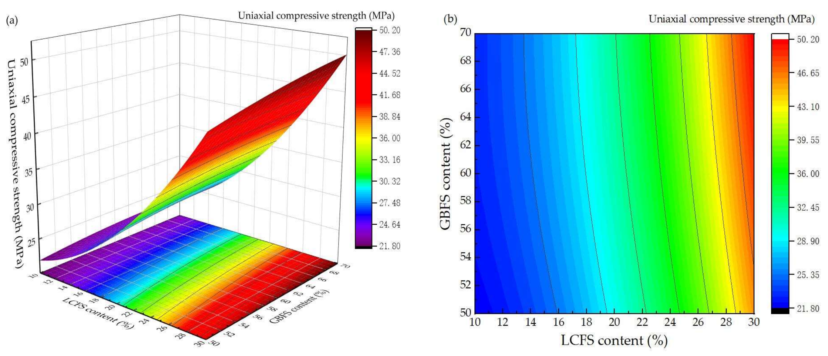
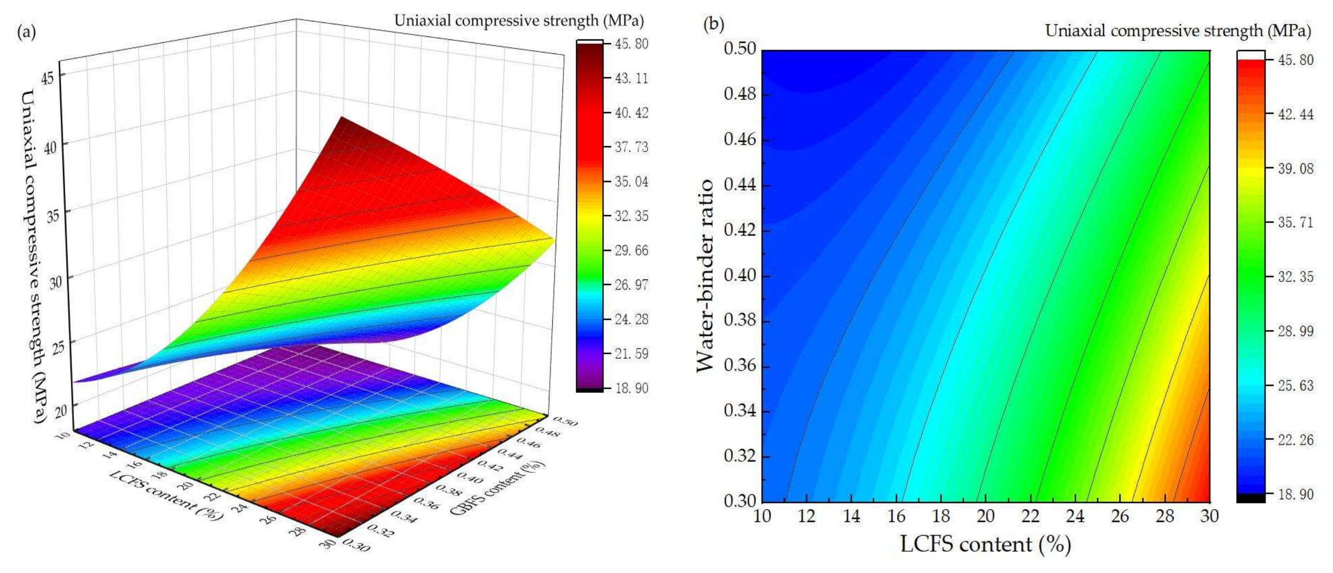
3.2. Response Surface Experiment Results and Analysis
3.3. Hydtation Degree Analysis
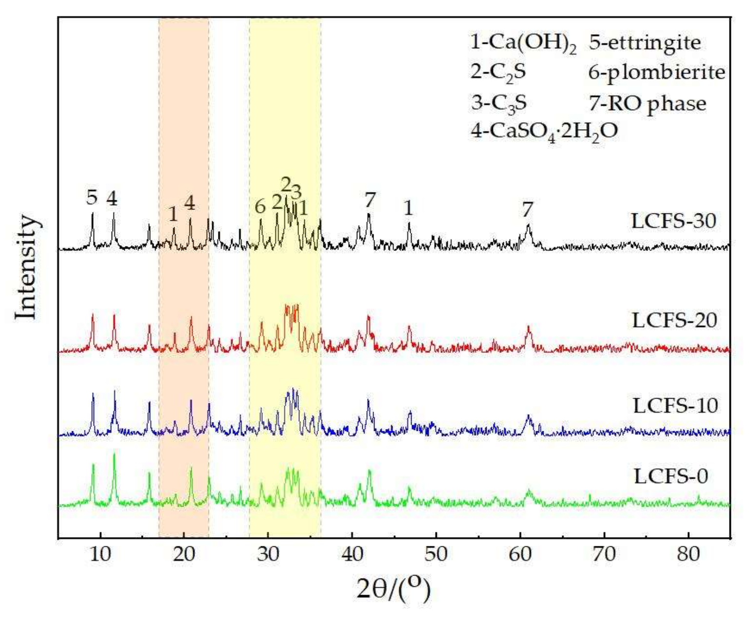
3.4. XRD Analysis
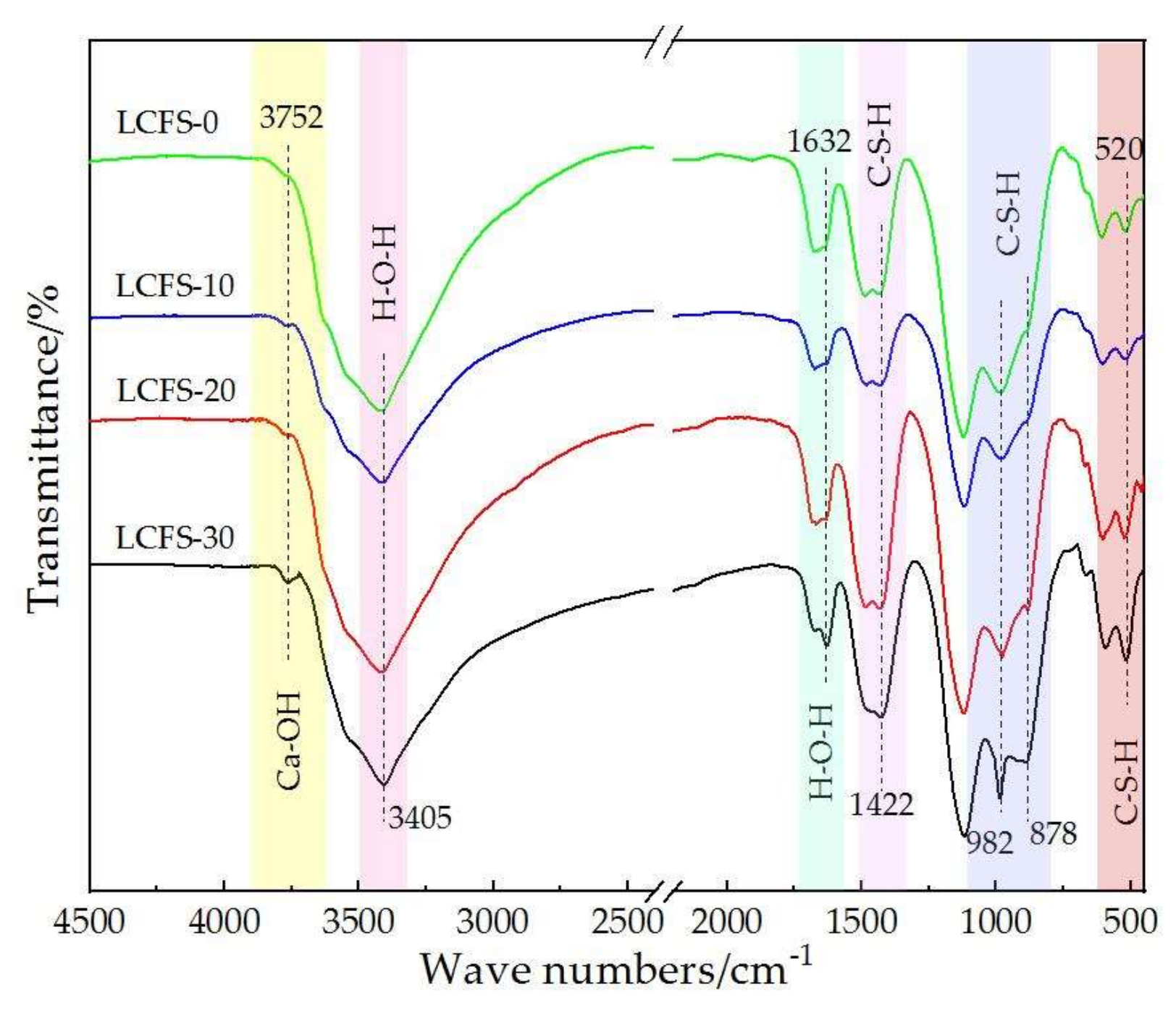
3.5. FTIR Analysis
3.6. Solid State NMR
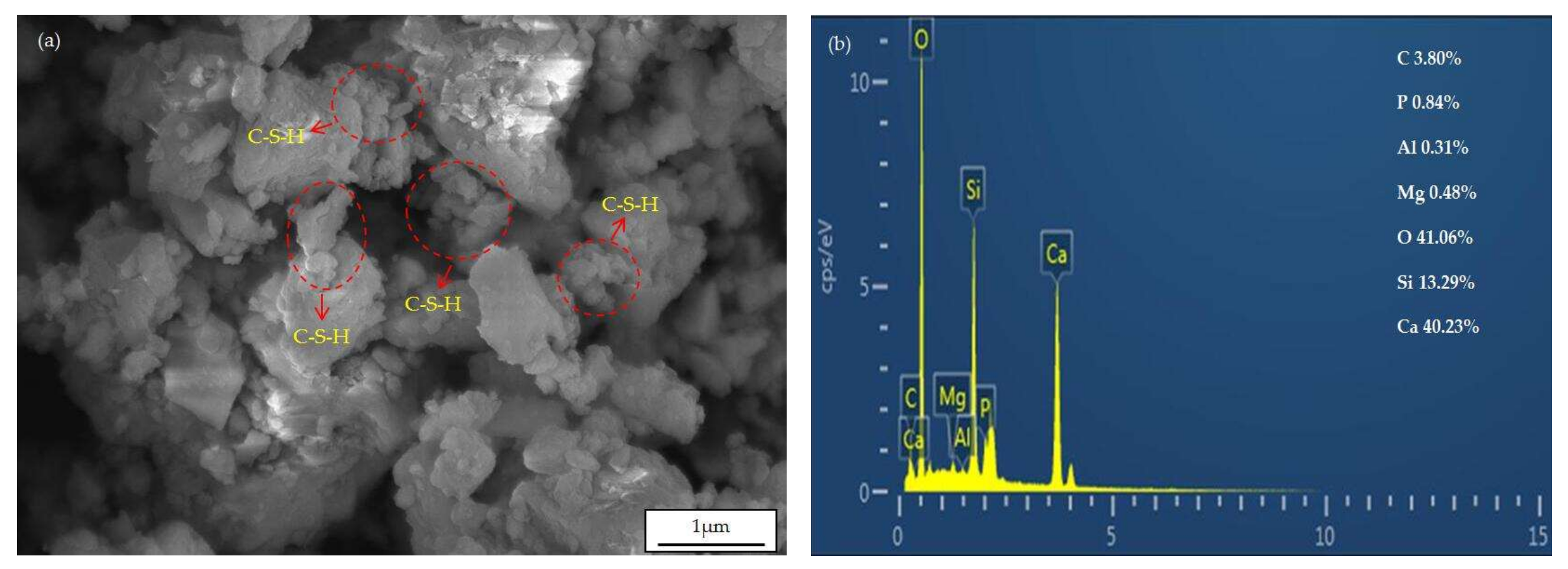
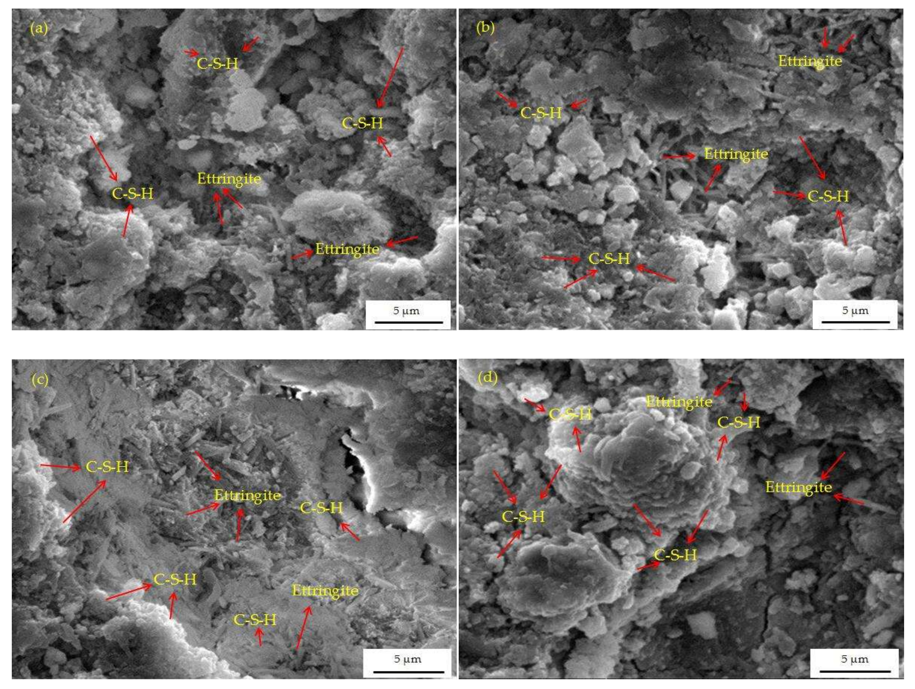
3.7. SEM Analysis
4. Applications
5. Conclusions
- (1)
- The LCFS has a hydration superposition effect to the composite cementitious materials, the compressive strength of the mortar samples by using LCFFS are significantly higher than the sample without LCFS.
- (2)
- The compressive strength of the mortar samples at 3, 7, and 28 days are 26.6, 35.3, and 42.7 MPa, respectively, when the LCFS-GBFS-SSM-FGDG ratio is 3:5:1:1 and the water-binder ratio is 0.3. The LCFS-GBFS composite cementitious materials have similar mechanical properties to cement-based materials.
- (3)
- Through the response surface design experiment, the ratio of LCFS-GBFS is the most important factor which can affect the compressive strength. The second factor is water-binder ratio.
- (4)
- The hydration products of LCFS-GBFS composite cementitious materials are C-S-H gels, and ettringite. The preliminary hydration mechanism of LCFS-GBFS composite cementitious materials are as follows: Firstly, the hydration of C2S, C3S in LCFS generates Ca(OH)2, C-S-H gels and many Ca2+ and OH−, they increase the alkalinity of the solution. Subsequently, the GBFS dissolve and release a large amount of (H2SiO4)2−, (H2AlO3)−, and react with Ca2+ in the solution and SO42−, which is dissolved by FGDG, then a large quantity of C-S-H gels and ettringite are generated. As the hydration process deepens, the minerals of SSM gradually dissolve, which promotes the further hydration of GBFS, and generates the hydration products. Finally, the synergistic hydration of LCFS-GBFS-SSM-FGDG is continuous, which promotes the production of more hydration products to fill the pore structure of cementitious system. This results in good compressive strength performance of the LCFS-GBFS composite cementitious materials.
Author Contributions
Funding
Institutional Review Board Statement
Informed Consent Statement
Data Availability Statement
Conflicts of Interest
References
- Chang, J.; Li, H.J.; Zheng, K.D.; Liu, C.G.; Wang, L.M.; Li, B.; Bu, X.N.; Shao, H.Z. Mineralogical Characterisation and Separation Studies on The Secovery of Cr2O3 in The High Carbon Ferrochrome Slag. Physicochem. Probl. Miner. Process. 2020, 56, 460–470. [Google Scholar] [CrossRef]
- Danish, A.; Totic, E.; Bayram, M.; Sutcu, M.; Gencel, O.; Erdogmus, E.; Ozbakkaloglu, T. Assessment of Mineralogical Characteristics of Clays and the Effect of Waste Materials on Their Index Properties for the Production of Bricks. Materials 2022, 15, 8908. [Google Scholar] [CrossRef] [PubMed]
- Kumar, P.; Sahu, N.; Roshan, A.; Rout, B.N.; Tripathy, S.K. Influence of Process Parameters on Impurity Level in Ferrochrome Production-An Industrial-Scale Analysis. Miner. Process. Extr. Metall. Rev. 2022, 43, 622–632. [Google Scholar] [CrossRef]
- Falayi, T.; Ikotun, B.D. A Comparison between Ferrochrome Slag and Gold Mine Tailings Based Geopolymers as Adsorbents for Heavy Metals in Aqueous Solutions: Analyzing Reusability and Sustainability. Korean J. Chem. Eng. 2021, 38, 816–825. [Google Scholar] [CrossRef]
- Manigandan, N.; Ponmalar, V. M5 Investigation on Ternary Binder Incorporated with Ferrochrome Slag Aggregate in Concrete. Appl. Nanosci. 2022, 12, 3925–3944. [Google Scholar] [CrossRef]
- Dash, M.K.; Patro, S.K.; Acharya, P.K.; Dash, M. Impact of Elevated Temperature on Strength and Micro-Structural Properties of Concrete Containing Water-Cooled Ferrochrome Slag as Fine Aggregate. Constr. Build. Mater. 2022, 323, 13–28. [Google Scholar] [CrossRef]
- Jena, S.; Panigrahi, R. Evaluation of Durability and Microstructural Properties of Geopolymer Concrete with Ferrochrome Slag as Coarse Aggregate. Iran. J. Sci. Technol. Trans. Civ. Eng. 2022, 46, 1201–1210. [Google Scholar] [CrossRef]
- Indu, P.; Greeshma, S. Elevated Temperature Study on Geopolymer Concrete with Ferrochrome Slag Aggregates. Cem. Wapno Beton 2021, 26, 340–351. [Google Scholar] [CrossRef]
- Dash, M.K.; Patro, S.K. Performance Assessment of Ferrochrome Slag as Partial Replacement of Fine Aggregate in Concrete. Eur. J. Environ. Civ. Eng. 2021, 25, 635–654. [Google Scholar] [CrossRef]
- Pei, D.J.; Li, Y.; Duan, X.J.; Cang, D.Q.; Yang, Y.D.; McLean, A.; Guo, Z.C.; Xu, C.H. Effect of Phase Composition on Leaching Behavior and Mechanical Properties of Ceramics from Ferrochrome Slag and Tundish Slag. Materials 2022, 15, 1993. [Google Scholar] [CrossRef]
- Omur, T.; Miyan, N.; Kabay, N.; Birol, B.; Oktay, D. Characterization of Ferrochrome Ash and Blast Furnace Slag Based Alkali-Activated Paste and Mortar. Constr. Build. Mater. 2023, 363, 19–32. [Google Scholar] [CrossRef]
- Khabibulin, E.E.; Khaydarov, B.B.; Suvorov, D.S.; Khaydarov, T.B.; Kozaev, A.A.; Lysov, D.V.; Kuznetsov, D.V. Production of Mineral Bindersbased on FERROALLOY SLAGS. Refract. Ind. Ceram. 2022, 63, 203–208. [Google Scholar] [CrossRef]
- Acharya, P.K.; Patro, S.K. Evaluation of Functional, Microstructural, Environmental Impact, and Economic Performance of Concrete Utilizing Ferrochrome Ash and Slag. J. Sustain. Metall. 2022, 8, 1573–1589. [Google Scholar] [CrossRef]
- Isil, S.K.; Hasan, B. Assessment of Reusing Ferrochrome Slag Wastes in Mortar as SCMs. J. Wuhan Univ. Technol. Mater. Sci. Ed. 2020, 35, 1043–1052. [Google Scholar] [CrossRef]
- Nath, S.K. Geopolymerization Behavior of Ferrochrome Slag and Fly Ash Blends. Constr. Build. Mater. 2018, 181, 487–494. [Google Scholar] [CrossRef]
- Kanavaris, F.; Soutsos, M.; Chen, J.F. Enabling Sustainable Rapid Construction with High Volume GGBS Concrete Through Elevated Temperature Curing and Maturity Testing. J. Build. Eng. 2023, 63, 21–40. [Google Scholar] [CrossRef]
- Mu, X.L.; Zhang, S.Q.; Ni, W.; Xu, D.; Li, J.J.; Du, H.H.; Wei, X.L.; Li, Y. Performance Optimization and Hydration Mechanism of A Clinker-Free Ultra-High Performance Concrete with Solid Waste Based Binder and Steel Slag Aggregate. J. Build. Eng. 2023, 63, 16–30. [Google Scholar] [CrossRef]
- Kim, T. Effects of Sodium Aluminate and Reverse Osmosis Brine on Hydration and Mechanical Properties of Slag. Constr. Build. Mater. 2022, 360, 15–23. [Google Scholar] [CrossRef]
- Sanjuan, M.A.; Rivera, R.A.; Martin, D.A.; Estevez, E. Chloride Diffusion in Concrete Made with Coal Fly Ash Ternary and Ground Granulated Blast-Furnace Slag Portland Cements. Materials 2022, 15, 8914. [Google Scholar] [CrossRef]
- Segura, I.P.; Luukkonen, T.; Yliniemi, J.; Sreenivasan, H.; Damo, A.J.; Jensen, L.S.; Canut, M.; Kantola, A.M.; Telkki, V.V.; Jensen, P.A. Comparison of One-Part and Two-Part Alkali-Activated Metakaolin and Blast Furnace Slag. J. Sustain. Metall. 2022, 8, 1816–1830. [Google Scholar] [CrossRef]
- Dai, J.P.; Wang, Q.C.; Zhang, X.; Bi, R.X.; Du, W.T. Effect of Content and Fineness of GGBS on Pore Structure of Cement Paste. J. Wuhan Univ. Technol. Mater. Sci. Ed. 2022, 37, 933–947. [Google Scholar] [CrossRef]
- Li, Y.B.; Lei, W.Y.; Zhang, Q.A.; Yang, Q.F.; He, X.Y.; Su, Y.; Tan, H.B.; Liu, J.; Wang, G. Synergistic Effects of Steel Slag and Wet Grinding on Ambient Cured Ground Granulated Blast Furnace Slag Activated by Sodium Sulfate. Constr. Build. Mater. 2022, 349, 15–31. [Google Scholar] [CrossRef]
- Park, B.; Choi, Y.C. Self-Healing Products of Cement Pastes with Supplementary Cementitious Materials, Calcium Sulfoaluminate and Crystalline Admixtures. Materials 2021, 14, 7201. [Google Scholar] [CrossRef] [PubMed]
- Pang, L.; Liao, S.C.; Wang, D.Q.; An, M.Z. Influence of Steel Slag Fineness on The Hydration of Cement-Steel slag composite pastes. J. Build. Eng. 2022, 57, 28–40. [Google Scholar] [CrossRef]
- Cui, C.Y.; Yu, C.Y.; Zhao, J.Y.; Zheng, J.J. Steel Slag/Precarbonated Steel Slag as a Partial Substitute for Portland Cement: Effect on the Mechanical Properties and Microstructure of Stabilized Soils. KSCE J. Civ. Eng. 2022, 26, 3803–3814. [Google Scholar] [CrossRef]
- Zhang, H.; Wang, L.; Long, H.M. Study on Composite Activating Mechanism of Alkali Steel Slag Cementations Materials by XRD and FTIR. Spectrosc. Spectr. Anal. 2018, 38, 2302–2306. [Google Scholar] [CrossRef]
- Roslan, N.H.; Ismail, M.; Abdul-Majid, Z.; Ghoreishiamiri, S.; Muhammad, B. Performance of Steel Slag and Steel Sludge in concrete. Constr. Build. Mater. 2016, 104, 16–24. [Google Scholar] [CrossRef]
- Zhao, J.H.; Li, Z.H.; Wang, D.M.; Yan, P.Y.; Luo, L.; Zhang, H.W.; Zhang, H.M.; Gu, X.B. Hydration Superposition Effect and Mechanism of Steel Slag Powder and Granulated Blast Furnace Slag Powder. Constr. Build. Mater. 2023, 366, 13–25. [Google Scholar] [CrossRef]
- Jiang, L.H.; Li, C.Z.; Wang, C.; Xu, N.; Chu, H.Q. Utilization of Flue Gas Desulfurization Gypsum As An Activation Agent For High-Volume Slag Concrete. J. Clean Prod. 2018, 205, 589–598. [Google Scholar] [CrossRef]
- Li, M.X.; Gu, K.; Chen, B. Effects of Flue Gas Desulfurization Gypsum Incorporation and Curing Temperatures on Magnesium Oxysulfate Cement. Constr. Build. Mater. 2022, 349, 9–20. [Google Scholar] [CrossRef]
- Wang, T.; Wu, K.; Wu, M. Development of Green Binder Systems Based on Flue Gas Desulfurization Gypsum and Fly Ash Incorporating Slag or Steel Slag Powders. Constr. Build. Mater. 2020, 265, 18–25. [Google Scholar] [CrossRef]
- Wansom, S.; Chintasongkro, P.; Srijampan, W. Water Resistant Blended Cements Containing Flue-Gas Desulfurization Gypsum, Portland Cement and Fly Ash for Structural Applications. Cem. Concr. Compos. 2019, 103, 134–148. [Google Scholar] [CrossRef]
- Liu, Y.L.; Su, Y.P.; Xu, G.Q.; Chen, Y.H.; You, G.S. Research Progress on Controlled Low-Strength Materials: Metallurgical Waste Slag as Cementitious Materials. Materials 2022, 15, 727. [Google Scholar] [CrossRef]
- Dhoble, Y.N.; Ahmed, S. Review on The Innovative Uses of Steel Slag for Waste Minimization. J. Mater. Cycles Waste Manag. 2018, 20, 1373–1382. [Google Scholar] [CrossRef]
- Matsimbe, J.; Dinka, M.; Olukanni, D.; Musonda, I. Geopolymer: A Systematic Review of Methodologies. Materials 2022, 15, 6852. [Google Scholar] [CrossRef]
- Wasim, M.; Ngo, T.D.; Law, D. A State-of-the-art Review on The Durability of Geopolymer Concrete for Sustainable Structures and Infrastructure. Constr. Build. Mater. 2021, 291, 21–35. [Google Scholar] [CrossRef]
- Li, Z.P. Multi-Objective Optimization of Gap-Graded Cement Paste Blended with Supplementary Cementitious Materials Using Response Surface Methodology. Constr. Build. Mater. 2020, 248, 11–26. [Google Scholar] [CrossRef]
- Wang, S.; Wang, C.L.; Wang, Q.H.; Liu, Z.Y.; Qian, W.; Jin, C.Z.; Chen, L.; Li, L. Study on Cementitious Properties and Hydration Characteristics of Steel Slag. Pol. J. Environ. Stud. 2018, 27, 357–364. [Google Scholar] [CrossRef]
- Li, Z.; Corr, D.J.; Han, B.G.; Shah, S.P. Investigating the Effect of Carbon Nanotube on Early age Hydration of Cementitious Composites with Isothermal Calorimetry and Fourier Transform Infrared Spectroscopy. Cem. Concr. Compos. 2020, 107, 8–20. [Google Scholar] [CrossRef]
- Wang, Z.C.; Wang, Z.C.; Xia, H.C. Analysis of Hydration Mechanism and Microstructure of Composite Cementitious Materials for Filling Mining. J. Wuhan Univ. Technol. Mater. Sci. Ed. 2017, 32, 910–913. [Google Scholar] [CrossRef]


| Composition | LCFS | GBFS | SSM | FGDG |
|---|---|---|---|---|
| CaO | 50.53 | 38.69 | 33.65 | 32.06 |
| SiO2 | 33.21 | 36.35 | 12.36 | 1.98 |
| Al2O3 | 9.53 | 16.23 | 1.97 | 0.77 |
| MgO | 1.02 | 9.27 | 5.31 | 1.16 |
| Na2O | - | 0.52 | 0.26 | 0.08 |
| Fe2O3 | 1.07 | 1.05 | 33.42 | 0.39 |
| MnO | 0.16 | 0.53 | 5.06 | 0.03 |
| TiO2 | 0.60 | 0.79 | 0.89 | 0.06 |
| K2O | 0.08 | 0.36 | 0.22 | 0.13 |
| SO3 | 0.08 | - | 0.13 | 43.89 |
| P2O5 | - | - | 1.62 | - |
| Mix Code | LCFS | GBFS | SSM | FGDG |
|---|---|---|---|---|
| LCFS-0 | 0 | 80 | 10 | 10 |
| LCFS-10 | 10 | 70 | 10 | 10 |
| LCFS-20 | 20 | 60 | 10 | 10 |
| LCFS-30 | 30 | 50 | 10 | 10 |
| Level | X1 | X2 | X3 |
|---|---|---|---|
| −1 | 10 | 50 | 0.3 |
| 0 | 20 | 60 | 0.4 |
| 1 | 30 | 70 | 0.5 |
Disclaimer/Publisher’s Note: The statements, opinions and data contained in all publications are solely those of the individual author(s) and contributor(s) and not of MDPI and/or the editor(s). MDPI and/or the editor(s) disclaim responsibility for any injury to people or property resulting from any ideas, methods, instructions or products referred to in the content. |
© 2023 by the authors. Licensee MDPI, Basel, Switzerland. This article is an open access article distributed under the terms and conditions of the Creative Commons Attribution (CC BY) license (https://creativecommons.org/licenses/by/4.0/).
Share and Cite
Ren, C.; Li, K.; Wang, Y.; Li, Y.; Tong, J.; Cai, J. Preparation and Hydration Mechanisms of Low Carbon Ferrochrome Slag-Granulated Blast Furnace Slag Composite Cementitious Materials. Materials 2023, 16, 2385. https://doi.org/10.3390/ma16062385
Ren C, Li K, Wang Y, Li Y, Tong J, Cai J. Preparation and Hydration Mechanisms of Low Carbon Ferrochrome Slag-Granulated Blast Furnace Slag Composite Cementitious Materials. Materials. 2023; 16(6):2385. https://doi.org/10.3390/ma16062385
Chicago/Turabian StyleRen, Chao, Keqing Li, Yonghua Wang, Yanfang Li, Jiannan Tong, and Jingyao Cai. 2023. "Preparation and Hydration Mechanisms of Low Carbon Ferrochrome Slag-Granulated Blast Furnace Slag Composite Cementitious Materials" Materials 16, no. 6: 2385. https://doi.org/10.3390/ma16062385
APA StyleRen, C., Li, K., Wang, Y., Li, Y., Tong, J., & Cai, J. (2023). Preparation and Hydration Mechanisms of Low Carbon Ferrochrome Slag-Granulated Blast Furnace Slag Composite Cementitious Materials. Materials, 16(6), 2385. https://doi.org/10.3390/ma16062385