
Experimental Studies of Welded Joints in Structures Subject to High Impact Vibrations Using Destructive and Non-Destructive Methods


Abstract
1. Introduction
2. The Essence of the Research Problem Based on the Literature
3. Materials and Methods
3.1. Execution of the Rail Joint
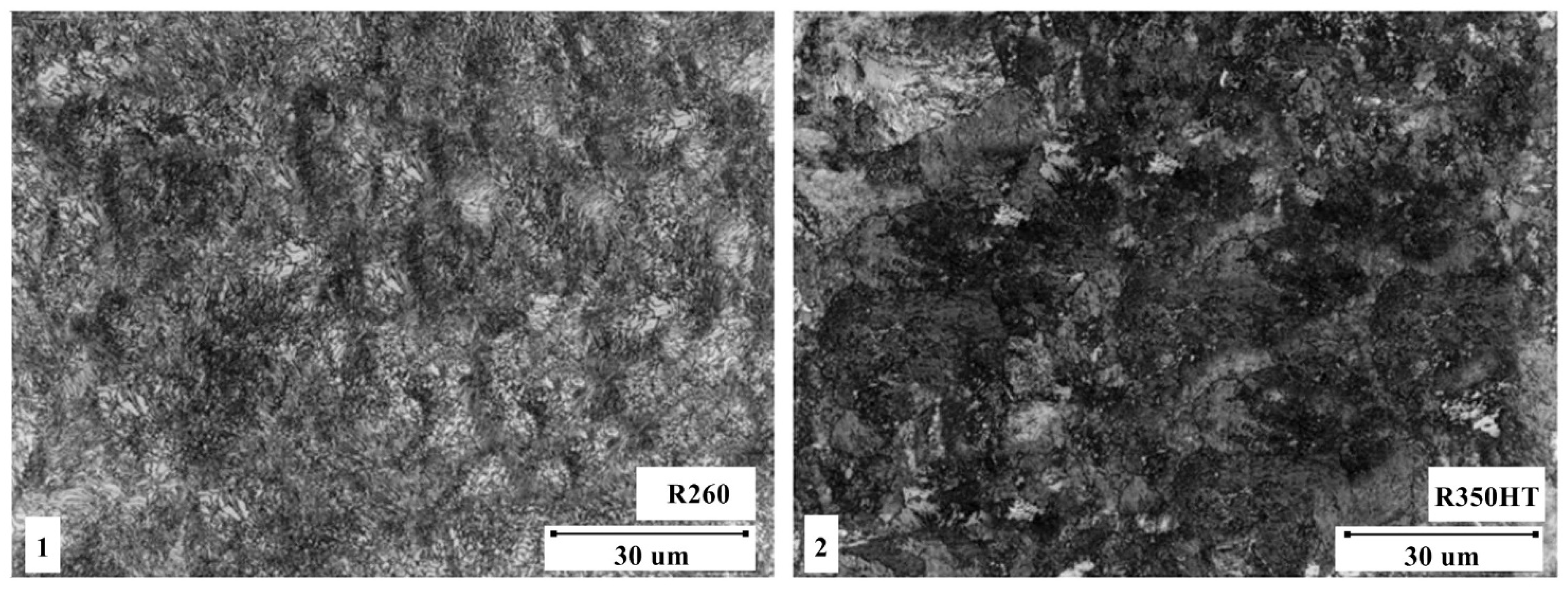
- Steel R260:
- -
- Yield strength (ReH): 260 N/mm2;
- -
- Strength limit (Rm): 380–420 N/mm2;
- -
- Elongation (A5): 26%;
- -
- Modulus of elasticity €: 200,000 N/mm2.
- Steel R350HT:
- -
- Yield strength (ReH): 350 N/mm2;
- -
- Strength limit (Rm): 550 N/mm2;
- -
- Elongation (A5): 16%;
- -
- Modulus of elasticity €: 210,000 N/mm2.
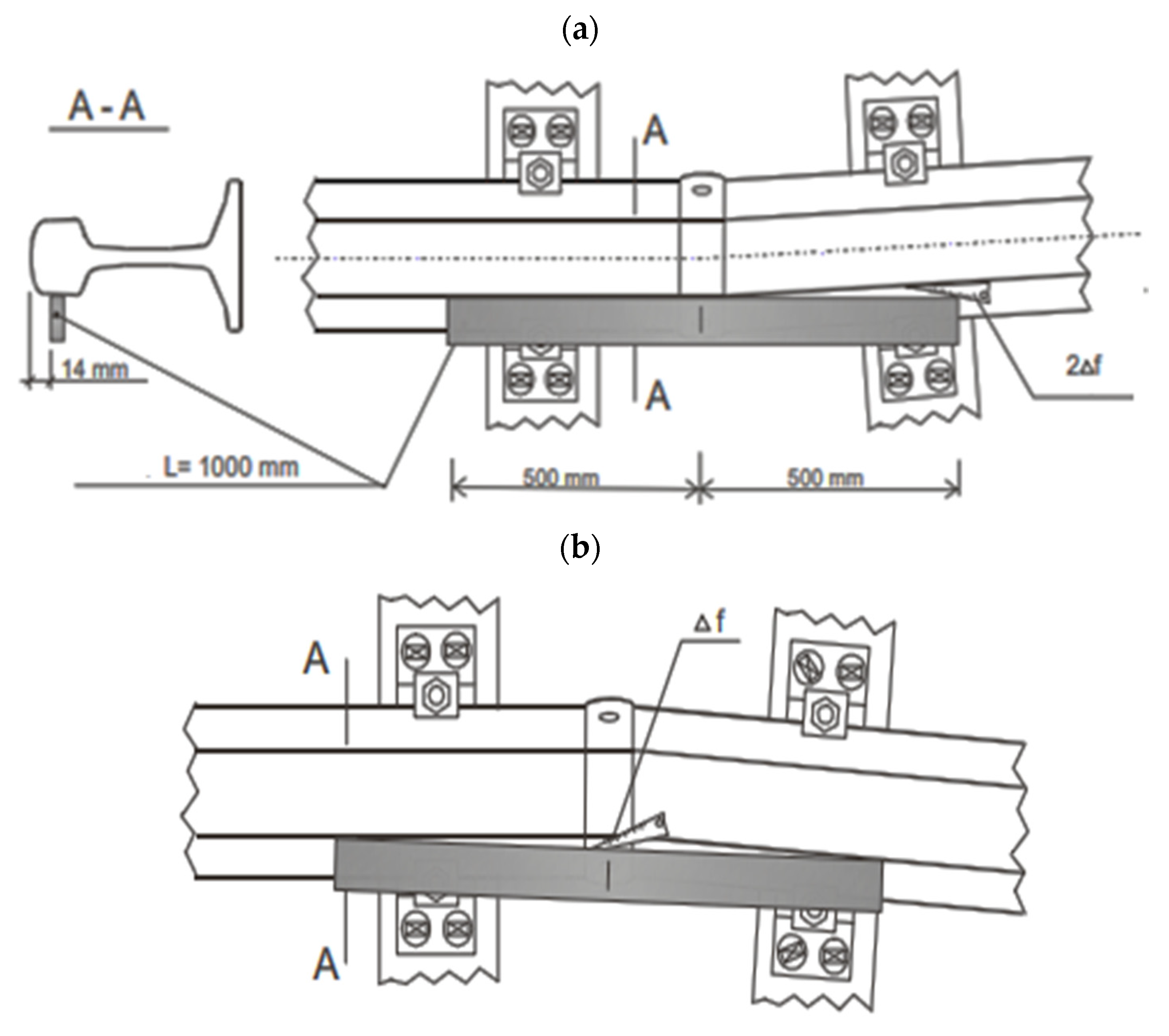
3.2. Checking the Rail Joints
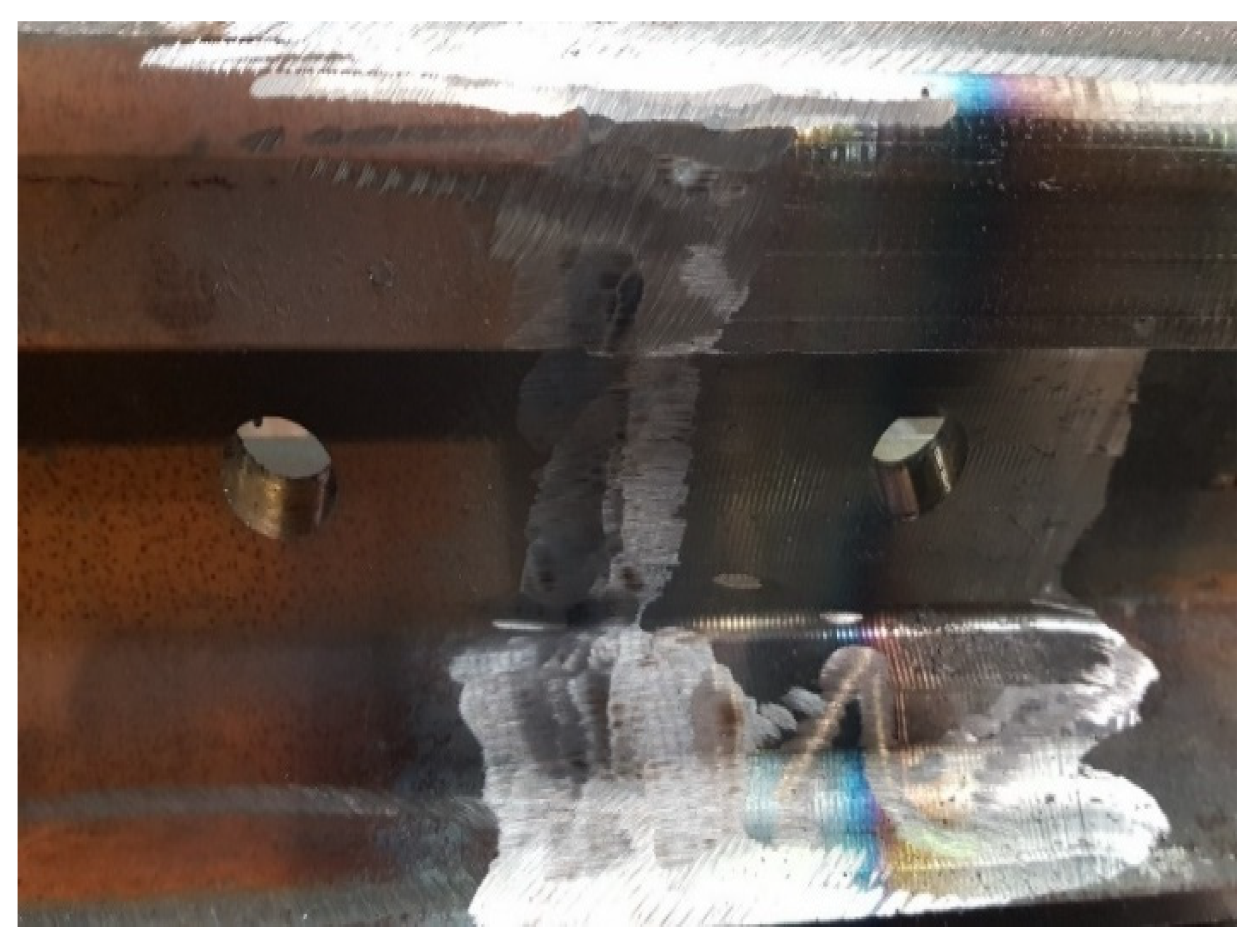
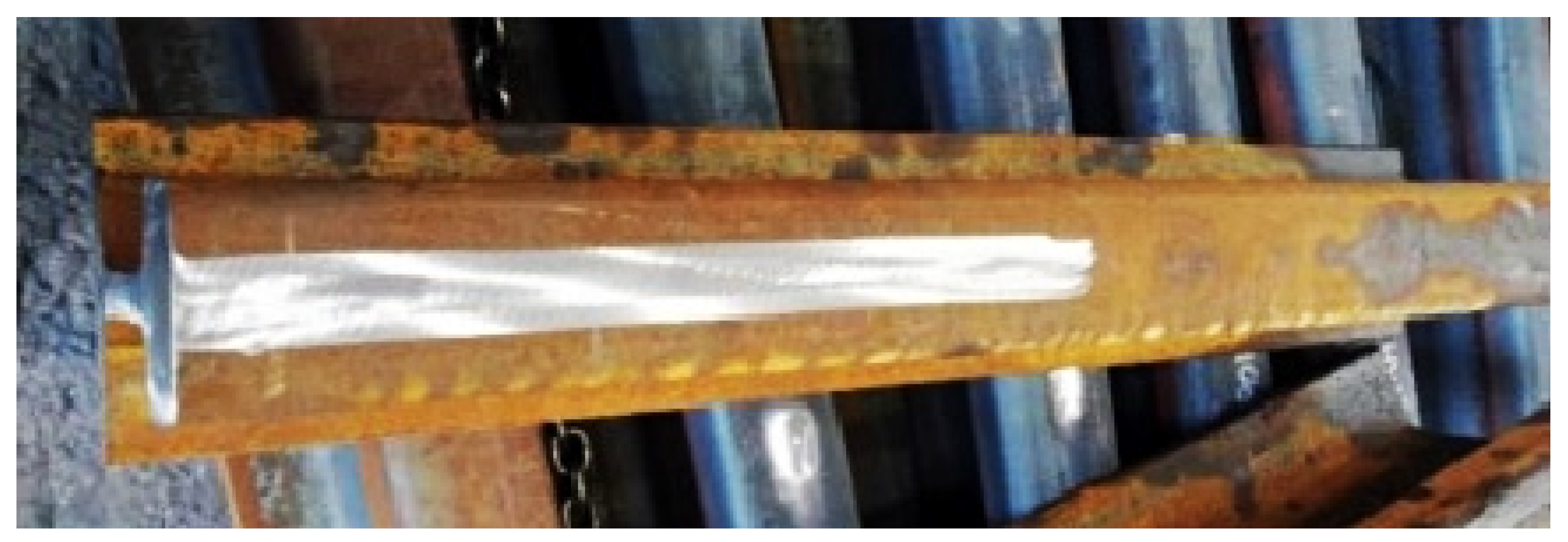
- Visual examination (VT);
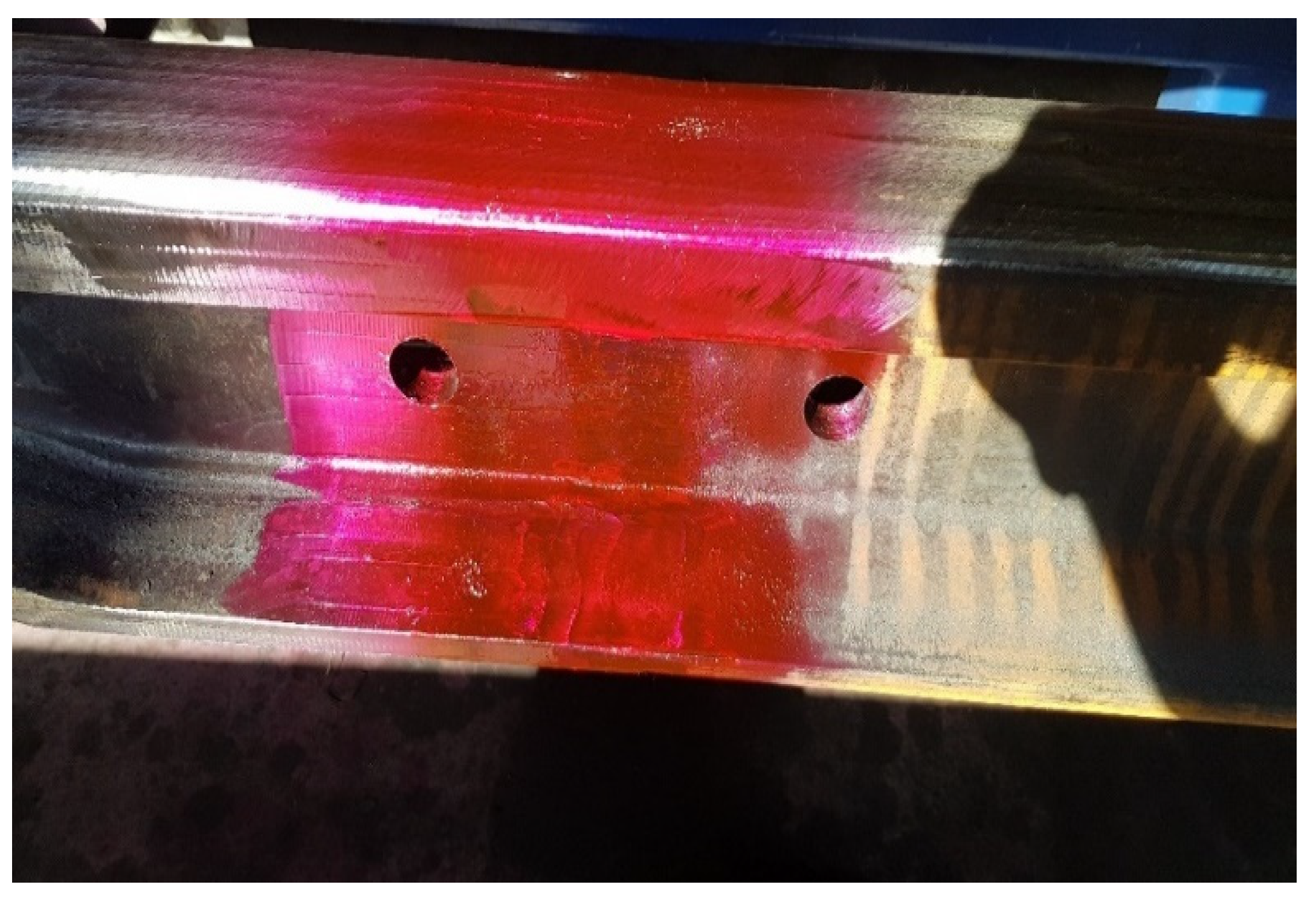
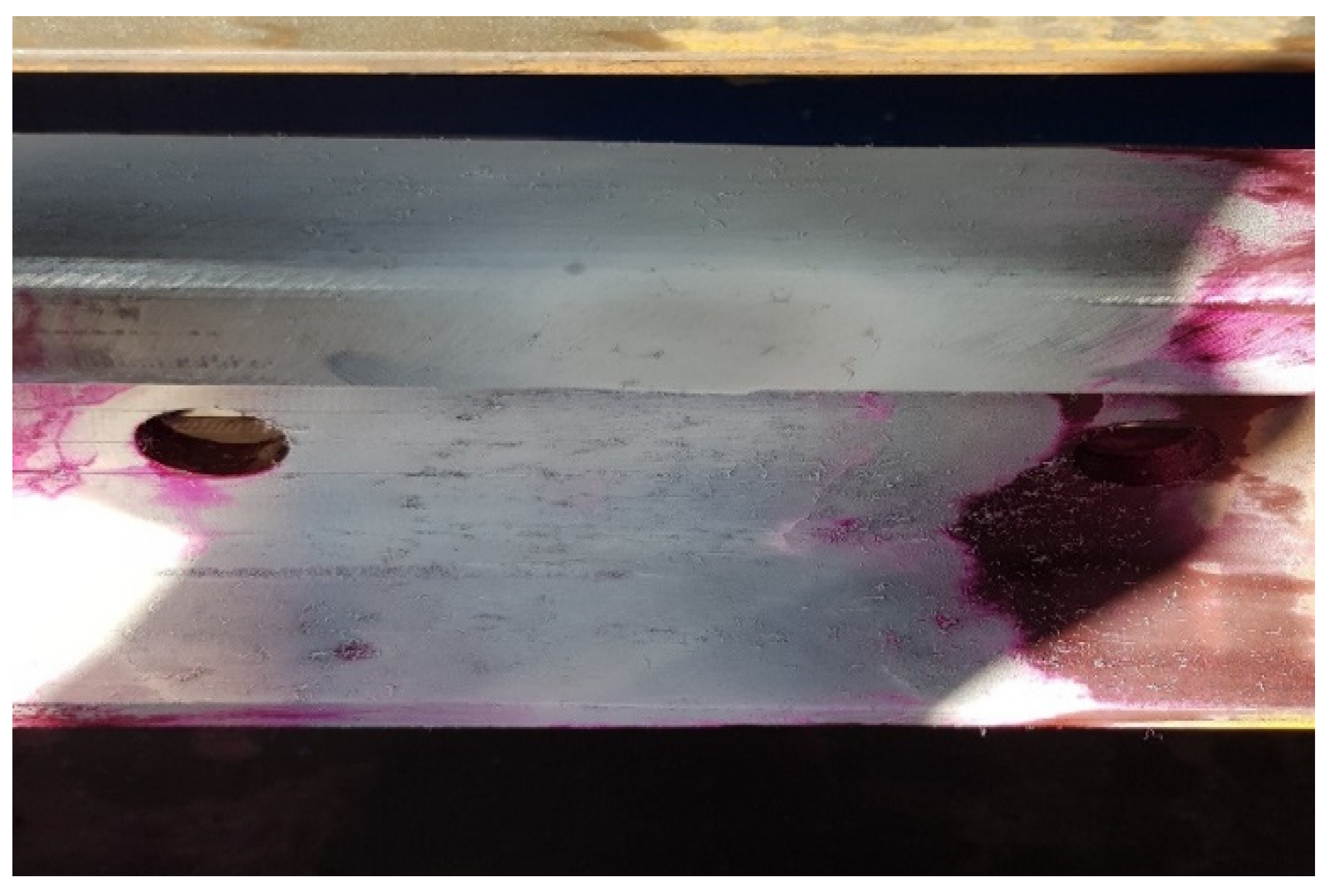
- Penetration testing (PT);
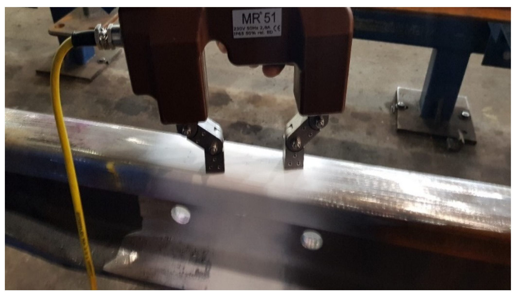
- Magnetic particle testing (MT).
- The illuminance on the test surface should be at least 350 lux, but the recommended illuminance value is 500 lux;
- The distance between the tested object and the examiner’s eye should not exceed 600 mm;
- The viewing angle must not be less than 30°;
- The tested surface must be clean and free of dirt and grease.
4. Results and Discussion
4.1. Checking the Rail Joints
- Ultrasonic testing: Uses an ultrasonic wave to detect inhomogeneities inside the rail, such as cracks or changes in density. The wave is sent down the bus and received on the other side, which allows any anomalies to be detected. An ultrasonic wave is sent into the rail and received on the other side, which allows any abnormalities to be detected. The mathematical formula that describes the motion of an ultrasonic wave is the equation of wave motion:
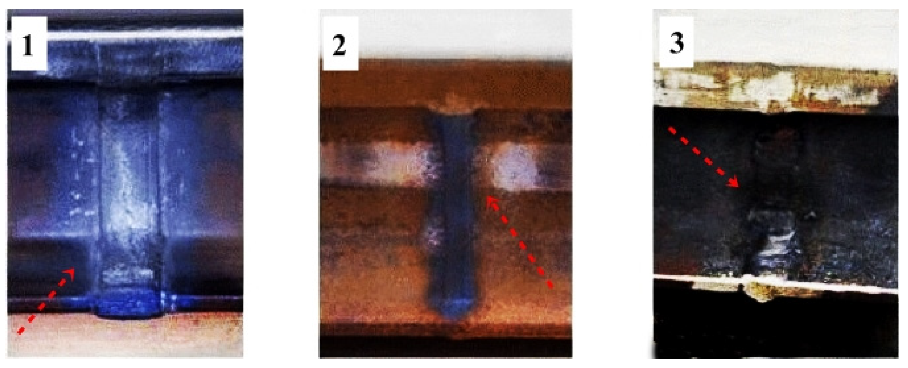
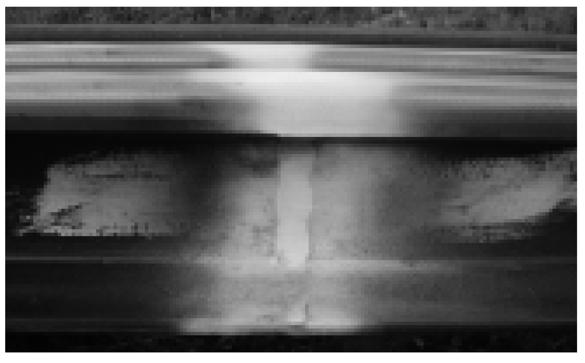
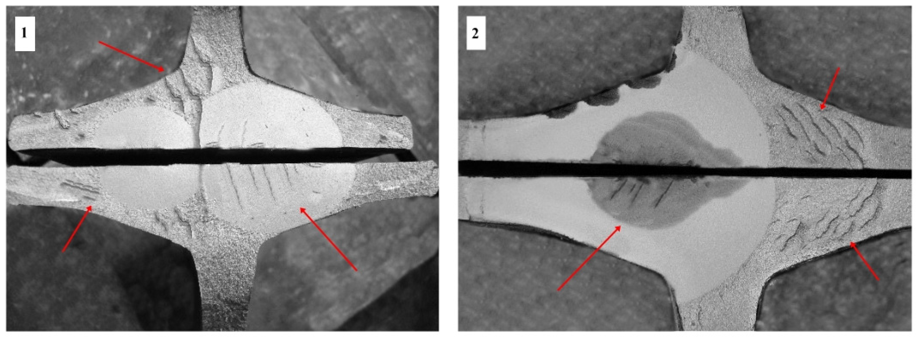
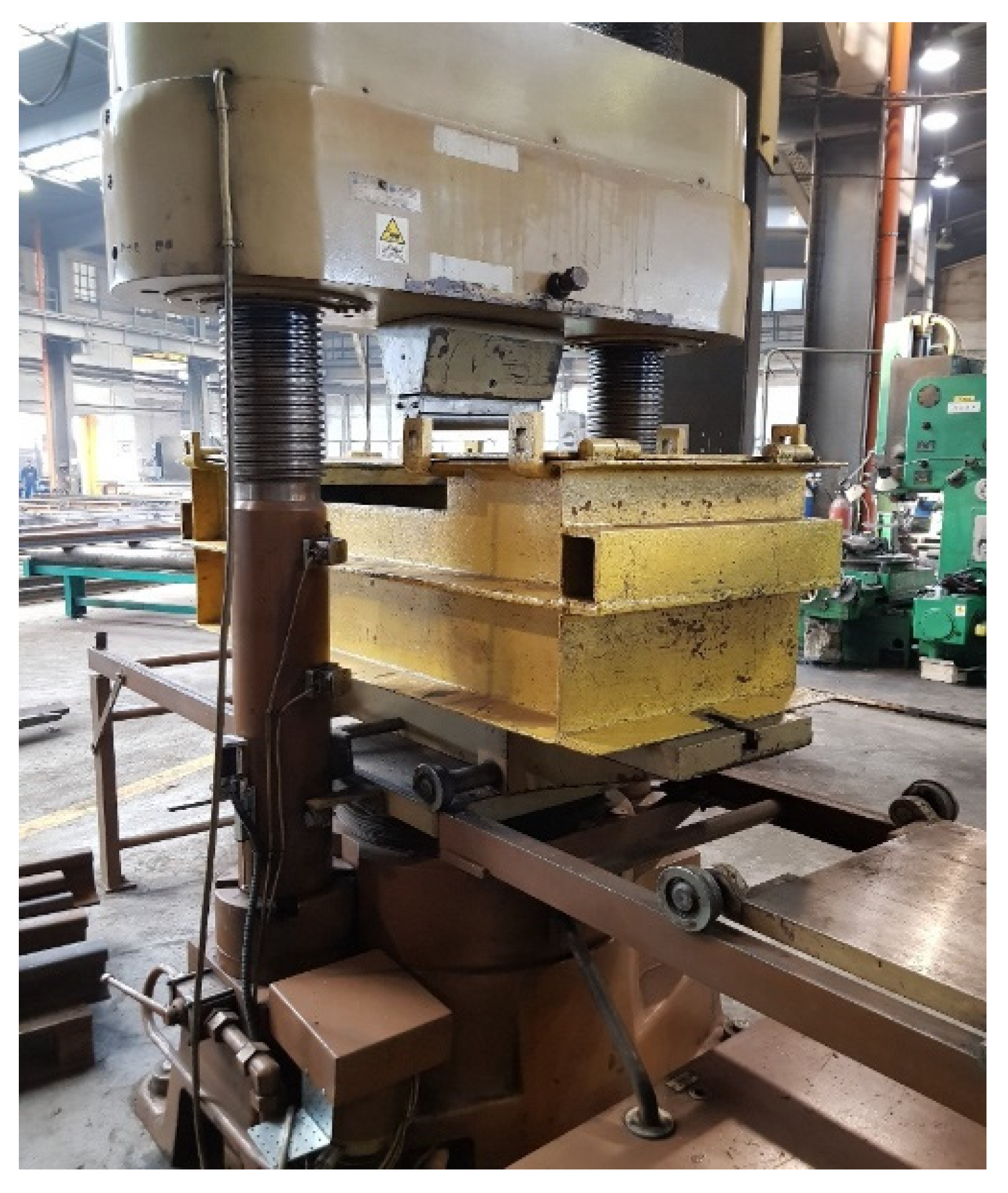
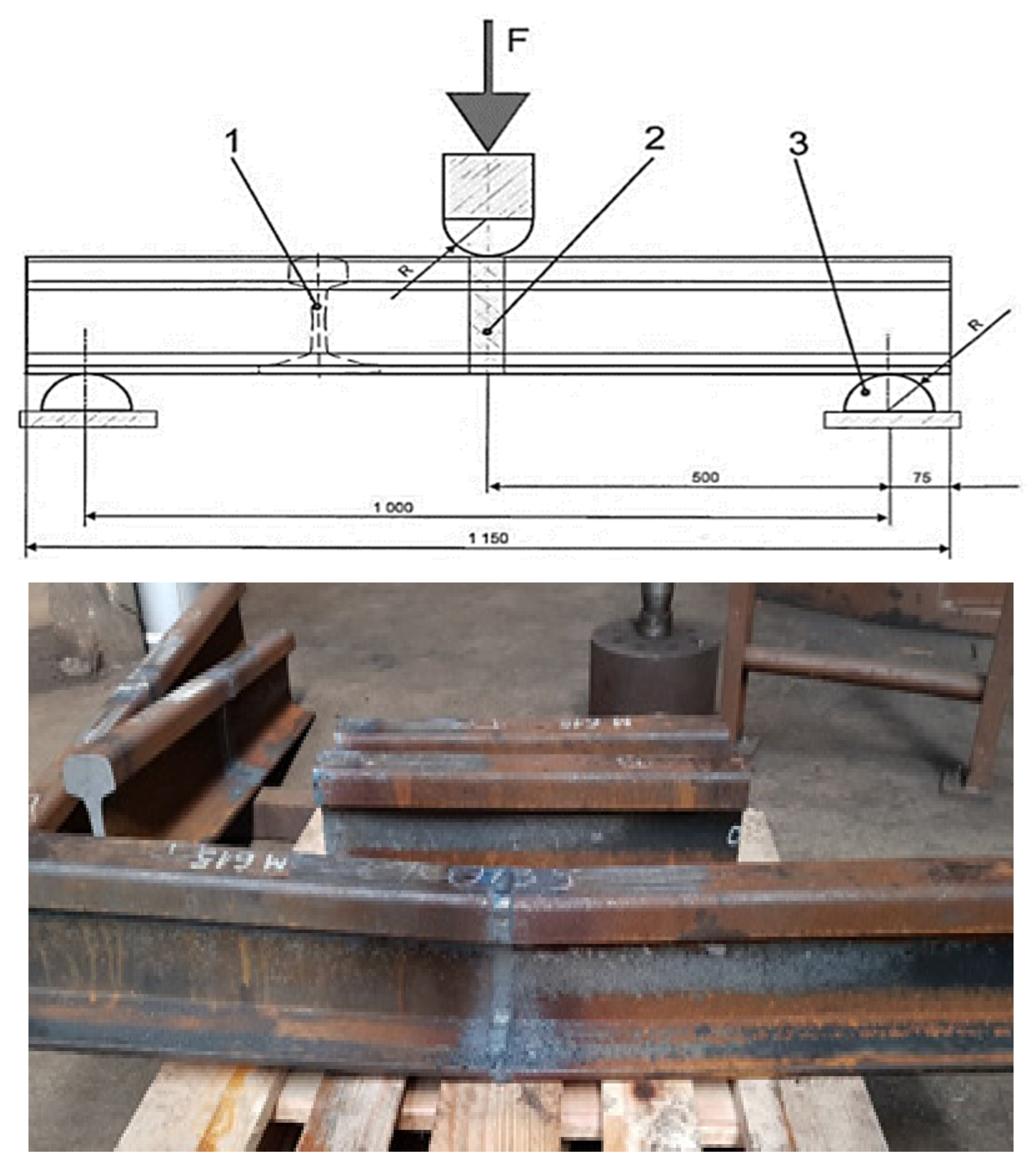
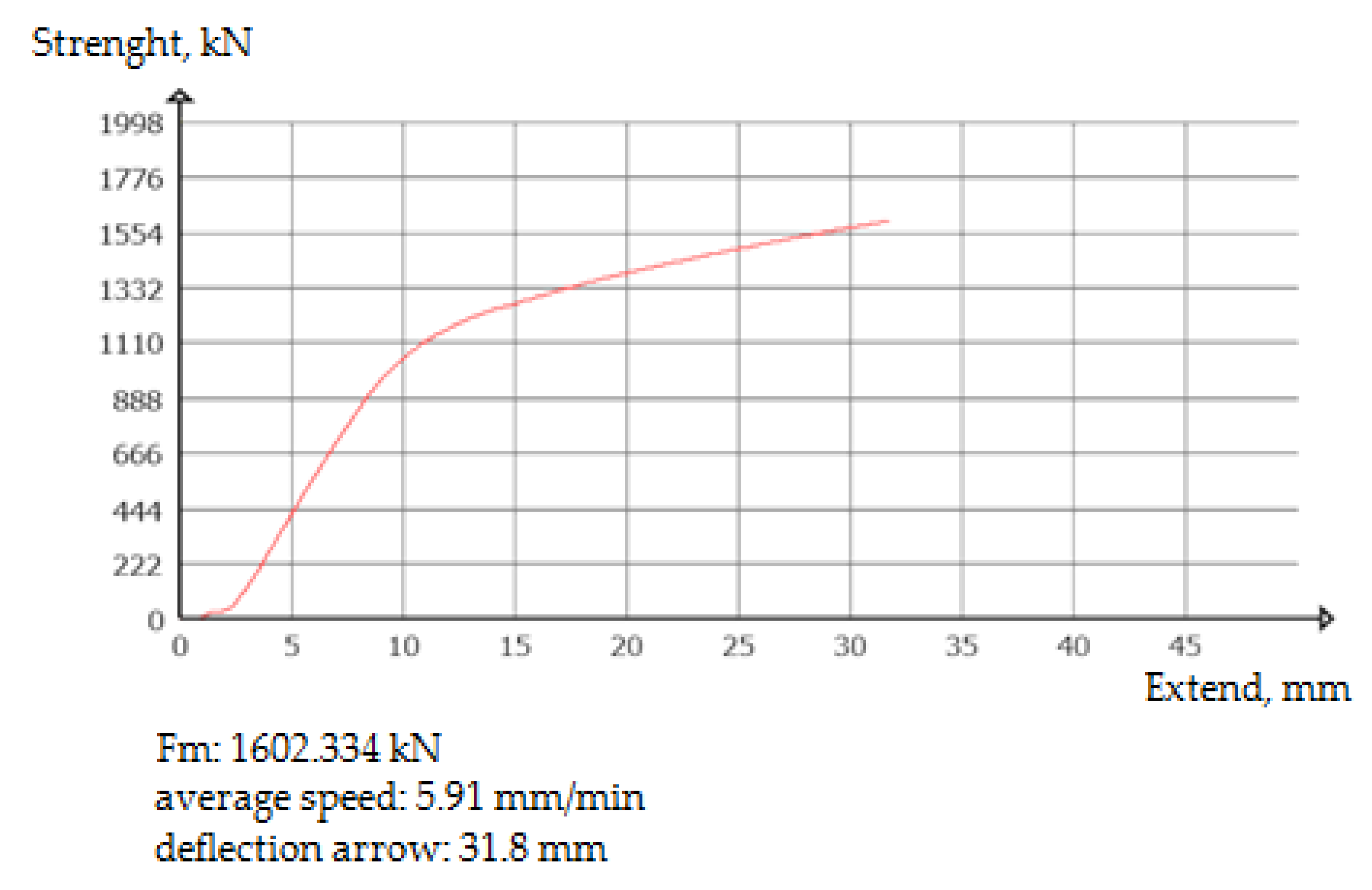
- Strength test: This consists of subjecting the rail sample to an appropriate load to determine its strength. After the sample has been destroyed, microscopic analysis can be performed to determine the cause of the damage. Strength testing of railway rails is one of the most important tests that are used to assess the strength and resistance of rails to damage and cracks during operation. In this test, the rail is subjected to a mechanical load and then the force required to break it is measured. One commonly used approach to strength testing is the constant load approach, where the rail is subjected to a constant mechanical load and then the force needed for it to fail is measured. This can be described by the following mathematical formula:
- Chemical Composition Testing: This involves taking a sample of the rail and performing a chemical analysis to determine its composition and quality. This method allows the detection of irregularities related to the production of rails, such as inadequate carbon content or insufficient content of other components. Testing the chemical composition of rails is one of the most important tests that is used to assess the quality and durability of rails. The purpose of this test is to determine the chemical composition of the material, including the amount of individual elements and the degree of its homogeneity. The procedure for testing the chemical composition of rails with regard to defects and faults may vary depending on the method and technology used by the laboratory, but generally consists of several steps:
- -
- Sample preparation: the rail sample is cut and subjected to preparation processes such as milling, shot peening or grinding to obtain the sample surface for analysis.
- -
- Chemical Analysis: chemical analysis is performed by various methods such as mass spectrometry, atomic absorption or emission spectrometry to determine the chemical composition of a sample.
- -
- Quality Assessment: chemical analysis is used to assess the quality of the splint, including its degree of homogeneity and the presence of any undesirable impurities or defects.
- -
- Fault Identification: if faults or defects are detected, further analysis is performed to determine their type and cause.
- -
- Reporting of results: at the end of the procedure, the results of the chemical composition test are reported in the form of an official document, which includes information on the chemical composition, quality and presence of faults or defects.
- -
- It does not damage the rails, which allows them to be reused and reduces disposal costs;
- -
- The speed and reliability of the test increases the safety of railway traffic;
- -
- They can be performed spontaneously, which allows for quick detection of faults and defects.
- -
- The accuracy of the results may be lower than those of destructive testing;
- -
- It requires special equipment and trained operators, which increases the cost of the examination;
- -
- It does not give a complete picture of the chemical composition and strength of the rail.
- -
- It gives a full picture of the chemical composition and strength of the rail material, which allows one to accurately determine its quality and durability;
- -
- It is very accurate and its results are easily proven;
- -
- It allows the detection of defects and faults that could pose a threat to the safety of railway traffic.
- -
- The test is destructive, which means that the rail is damaged or destroyed during the test;
- -
- Several tests may be required to get a full picture of the rail chemistry and strength, adding to the cost of testing;
- -
- Sometimes it is difficult to determine whether a fault is serious or not, which can lead to unnecessary rail replacement.
4.2. Non-Destructive Testing Program
5. Conclusions
- -
- When welding high-strength rails, in order to obtain the required mechanical properties of the welded joints, it is necessary to reduce the energy input compared to existing technologies for rail joints not subjected to heating.
- -
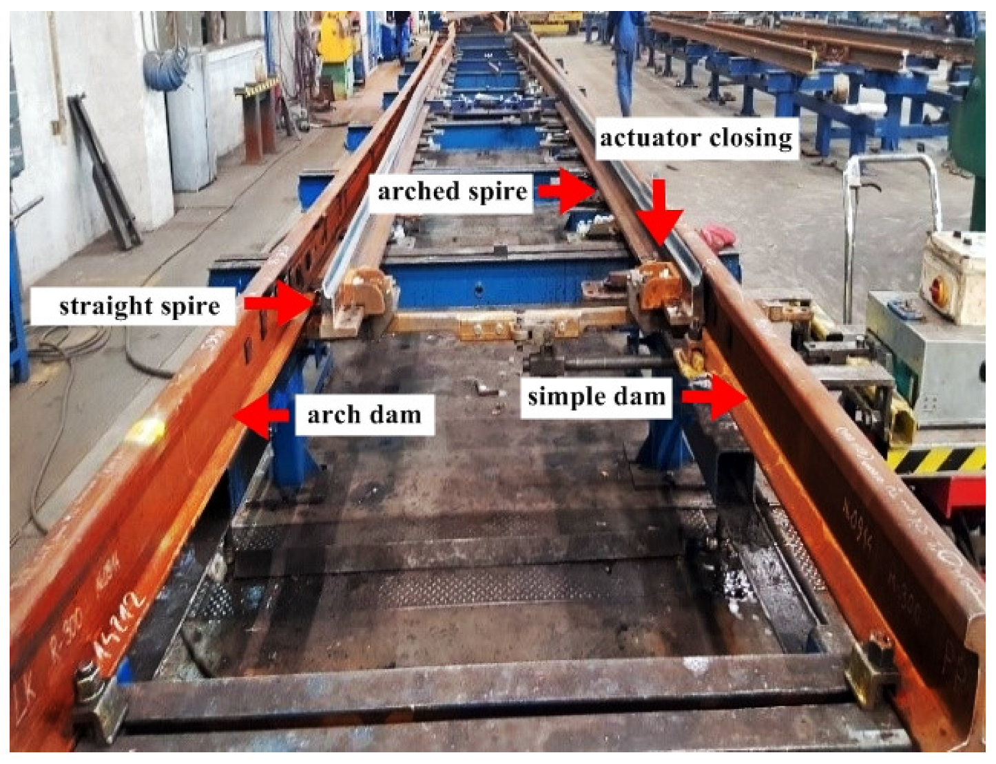
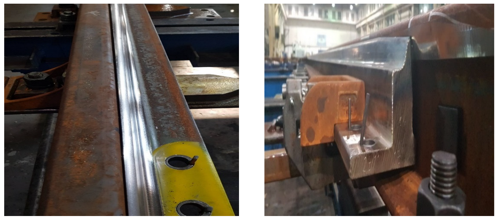
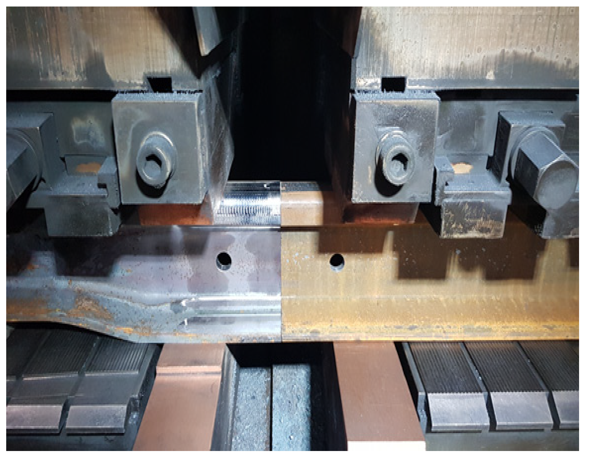
- The use of the K922 machine allowed the use of a new technology for stabilization of temperature stresses on tracks welded continuously using the stress welding method. The methods of making the welded rail joint were made in accordance with the recommendations contained in the standards and technical conditions.
- -
- Laboratory tests of rail joints confirm the good quality of rail joints, both from the welding shop and those made on the track. Increasingly less damage to the track at the location of new welded joints is proof that the methodology of laboratory tests is correct and fulfils its task. This type of research has its limitations. From the scientific point of view, it should be emphasized that the adopted joint production and quality testing techniques, depending on the location and size of defects, may significantly differ in their selection. Penetration testing can be carried out almost anywhere, but this limits the penetration time. Magnetic particle testing is very fast, but the limitation is the current source needed to magnetize the surface by the device. For these two studies, the choice is up to the researcher.
Author Contributions
Funding
Institutional Review Board Statement
Informed Consent Statement
Data Availability Statement
Conflicts of Interest
References
- Mikłaszewicz, I. Execution and testing of rail joints. Railw. Probl. 2013, 158. [Google Scholar]
- Mikno, Z.; Szebeszczyk, T.; Czylok, K. Quality control of the resistance spark butt welding process. Weld. Rev. 2015, 87, nr 8. [Google Scholar]
- PN-EN 14587-1:2019; Railways—Infrastructure—Flash Welding of New Rails—Part 1: Welding of R220, R260, R260Mn, R320Cr, R350HT, R350LHT, R370CrHT and R400HT Rails in a Welding Shop. 2019. Available online: https://standards.iteh.ai/catalog/standards/cen/d179a2e2-dae6-4079-b8ee-7288cc8b88b3/en-14587-1-2018 (accessed on 19 January 2023).
- PN-EN 14587-2:2009; Railway Industry—Track—Flash Welding of Rails—Part 2: Welding of New Rails Made of Steel Grades R220, R260, R260Mn and R350HT with Track Welding Machines Outside the Welding One. 2009. Available online: https://standards.iteh.ai/catalog/standards/cen/e61d3401-8391-4ba1-83fd-5c82df71da2d/en-14587-2-2009 (accessed on 19 January 2023).
- Niekurzak, M.; Mikulik, J. Modeling of Energy Consumption and Reduction of Pollutant Emissions in a Walking Beam Furnace Using the Expert Method—Case Study. Energies 2021, 14, 8099. [Google Scholar] [CrossRef]
- Sałaciński, T.; Sosnowski, W. Quality supervision system for welding processes in accordance with the requirements of ISO 3834 based on ISO 9001 standards—Part 1. Weld. Rev. 2015, 87, nr 4. [Google Scholar]
- Tokareva, A.E. Restoration of Defective Rail Sections. Put’ Putevoye Khozyajstvo 2002, 4. [Google Scholar]
- Makuch, J. Presentation. Rail Diagnostics, Rail Defects. Cathedral of Bridges and Railways; Deputy J. New Techniques of Ultrasonic Testing; Wroclaw University of Science and Technology: Wrocław, Poland, 2015; Available online: https://docplayer.pl/20082721-Wyklad-3-diagnostyka-nawierzchni-instrukcja-id-14.html (accessed on 19 January 2023).
- Mackiewicz, S. Testing of welded joints using the Phased Array technique in the light of the requirements of PN-EN 13588. Weld. Rev. 2015, 12, 101–106. [Google Scholar]
- Sałaciński, T.; Sosnowski, W. Quality supervision system for welding processes in accordance with the requirements of ISO 3834 based on ISO 9001 standards—Part 2. Weld. Rev. 2015, 87, nr 6. [Google Scholar]
- Kuchuk-Yatsenko, S.I. Defects of joints of high-strength rails produced using flash-butt welding. Avtom. Svarka 2013, 9, 3–9. [Google Scholar]
- Stencel, G. Welding of surface elements in the aspect of railroad maintenance and traffic safety. Transp. Infrastruct. 2011, 4, 78–83. [Google Scholar]
- Strach, M.; Piekarz, M. Modern devices in railway road measurements. Railw. Probl. 2009, 148, 48–60. [Google Scholar]
- Theile, D.; Wysocki, M. Thermite welding. In Practice and experience with the SKV method (with short heating time). In Proceedings of the 5th National Scientific and Technical Conference “Welding of Rail Roads”, Krakow, Poland, 15–17 May 2013; p. 25. [Google Scholar]
- Wenty, R. Latest Developments in Track Rehabilitation and Maintenance. RTR Spec. 2007, 37–42. [Google Scholar]
- Wielgosz, R. Connecting contactless railway rails. Mech. Tech. J. Publ. House Crac. Univ. Technol. 2009, 6, 1–7. [Google Scholar]
- Kaewunruen, S.; Ngamkhanong, C.; Goto, K.; Janeliukstis, R. Asymmetrical effects on railway turnout bearers due to wheelset impact over a crossing nose. In The 5th International Conference on Road and Rail Infrastructure; University of Zagreb: Zagreb, Croatia, 2018; pp. 623–629. [Google Scholar] [CrossRef]
- da Silva, A.L.; Correia, J.A.; de Jesus, A.M.; Lesiuk, G.; Fernandes, A.A.; Calçada, R.; Berto, F. Influence of fillet end geometry on fatigue behaviour of welded joints. Int. J. Fatigue 2019, 123, 196–212. [Google Scholar] [CrossRef]
- Ding, Y.; Zhong, W.; Sun, P.; Cao, B.; Song, Y. Fatigue Life Evaluation of Welded Joints in OSD for Railway Bridges Considering Welding Residual Stress. J. Perform. Constr. Facil. 2019, 33, 04018111. [Google Scholar] [CrossRef]
- Nikulina, A.; Porechina, A.; Khlebnikov, S.; Bataeva, Z.; Potapov, V. Microstructural Features of Welded Railway Frogs formed by Flash Butt Welding and Pulse-Arc Cladding. Met. Work. Mater. Sci. 2020, 22, 53–62. [Google Scholar] [CrossRef]
- Deepak, J.; Raja, V.B.; Kavitha, K.; Reddy, K.G.; Venkat, M. Microstructure and metallurgical property investigation of welded IRSM 41-97 rail steel joints. Mater. Today Proc. 2021, 47, 4827–4832. [Google Scholar] [CrossRef]
- Murakami, Y.; Takagi, T.; Wada, K.; Matsunaga, H. Essential structure of S-N curve: Prediction of fatigue life and fatigue limit of defective materials and nature of scatter. Int. J. Fatigue 2021, 146, 106138. [Google Scholar] [CrossRef]
- Kuzmin, E.V.; Gorbunov, O.E.; Plotnikov, P.O.; Tyukin, V.A.; Bashkin, V.A. Application of Neural Networks for Recognizing Rail Structural Elements in Magnetic and Eddy Current Defectograms. Autom. Control. Comput. Sci. 2019, 53, 628–637. [Google Scholar] [CrossRef]
- Żurek, J.; Ziółkowski, J.; Borucka, A. A method for determination of combat vehicles availability by means of statistic and econometric analysis, Safety and Reliability. Theory Appl. ESREL 2017, 2925–2934. [Google Scholar] [CrossRef]
- Żurek, J.; Ziółkowski, J.; Borucka, A. Application of Markov processes to the method for analysis of combat vehicle operation in the aspect of their availability and readiness, Safety and Reliability. Theory Appl. ESREL 2017, 2343–2352. [Google Scholar] [CrossRef]
- Żurek, J.; Ziółkowski, J.; Borucka, A. Research of automotive vehicles operation process using the Markov model, Safety and Reliability. Theory Appl. ESREL 2017, 2353–2362. [Google Scholar] [CrossRef]
- Żurek, J.; Zieja, M.; Ziółkowski, J. Reliability of supplies in a manufacturing enterprise. In Safety and Reliability—Safe Societies in a Changing World, Proceedings of the 28th International European Safety and Reliability Conference, ESREL 2018, Trondheim, Norway, 17–21 June 2018; CRC Press: Boca Raton, FL, USA, 2018; pp. 3143–3148. [Google Scholar]
- Żurek, J.; Małachowski, J.; Ziółkowski, J.; Szkutnik-Rogoż, J. Reliability Analysis of Technical Means of Transport. Appl. Sci. 2020, 10, 3016. [Google Scholar] [CrossRef]
- Oszczypała, M.; Ziółkowski, J.; Małachowski, J. Reliability Analysis of Military Vehicles Based on Censored Failures Data. Appl. Sci. 2022, 12, 2622. [Google Scholar] [CrossRef]
- Tadeusz, D. Experimental research on separation efficiency of aerosol particles in vortex tube separators with electric field, Bulletin of the Polish Academy of Sciences. Tech. Sci. 2020, 68, 503–516. [Google Scholar] [CrossRef]
- Tadeusz, D.; Sebastian, D. A Study on the Effect of Inlet Air Pollution on the Engine Component Wear and Operation. Energies 2022, 15, 1182. [Google Scholar] [CrossRef]
- Dziubak, T. The effects of dust extraction on multi-cyclone and non-woven fabric panel filter performance in the air filters used in special vehicles. Eksploat. Niezawodn. 2016, 18, 348–357. [Google Scholar] [CrossRef]
- Dziubak, T.; Boruta, G. Experimental and Theoretical Research on Pressure Drop Changes in a Two-Stage Air Filter Used in Tracked Vehicle Engine. Separations 2021, 8, 71. [Google Scholar] [CrossRef]
- Dziubak, T. Experimental Investigation of Possibilities to Improve Filtration Efficiency of Tangential Inlet Return Cyclones by Modification of Their Design. Energies 2022, 15, 3871. [Google Scholar] [CrossRef]
- Tajalli, M.R.; Zakeri, J.A. Investigating the Effect of Some Train and Track Parameters on Contact-impact Forces in the Vicinity of a Rail Breakage. Period. Polytech. Civ. Eng. 2019, 63, 938–946. [Google Scholar] [CrossRef]
- Nichoha, V.; Storozh, V.; Matiieshyn, Y. Results of research of the eight-channel sensor for the defectoscopy of railway rails. Proc. SPIE 2020, 11442, 114421A. [Google Scholar] [CrossRef]
- Shi, H.; Shi, L.; Ding, H.; Wang, W.; Jiang, W.; Guo, J.; Liu, Q. Influence of laser strengthening techniques on anti-wear and anti-fatigue properties of rail welding joint. Eng. Fail. Anal. 2019, 101, 72–85. [Google Scholar] [CrossRef]
- Salehi, I.; Kapoor, A.; Mutton, P. Multi-axial fatigue analysis of aluminothermic rail welds under high axle load conditions. Int. J. Fatigue 2011, 33, 1324–1336. [Google Scholar] [CrossRef]
- Li, W.; Xiao, G.; Wen, Z.; Xiao, X.; Jin, X. Plastic deformation of curved rail at rail weld caused by train–track dynamic interaction. Wear 2011, 271, 311–318. [Google Scholar] [CrossRef]
- Xu, X.; Xiao, B.; Liu, J.; Sun, S. Research on the dynamic response characteristics of rail joints of high speed railway. China Railw. 2021, 1, 46–53. [Google Scholar] [CrossRef]
- Jiang, W.; Wang, W.; Ding, H.; Guo, J.; Liu, Q. Damage behavior of U71Mn steel rail gas pressure welded joint, Materials for. Mech. Eng. 2021, 45, 43–48. [Google Scholar] [CrossRef]
- Zhang, Y.; Liu, F.; Li, C.; Yang, G.; Zhou, S. Comparison of rail technology for high speed railway between China and France. China Railw. 2020, 1, 115–121. [Google Scholar] [CrossRef]
- Wang, Y.-Q.; Zhou, H.; Shi, Y.-J.; Feng, B.-R. Mechanical properties and fracture toughness of rail steels and thermite welds at low temperature. Int. J. Miner. Met. Mater. 2012, 19, 409–420. [Google Scholar] [CrossRef]
- Porcaro, R.R.; Faria, G.L.; Godefroid, L.B.; Apolonio, G.R.; Cândido, L.C.; Pinto, E.S. Microstructure and mechanical properties of a flash butt welded pearlitic rail. J. Mater. Process. Technol. 2019, 270, 20–27. [Google Scholar] [CrossRef]
- Su, H.; Li, J.; Lai, Q.; Pun, C.L.; Mutton, P.; Kan, Q.; Kang, G.; Yan, W. Ratcheting behaviour of flash butt welds in heat-treated hypereutectoid steel rails under uniaxial and biaxial cyclic loadings. Int. J. Mech. Sci. 2020, 176, 105539. [Google Scholar] [CrossRef]
- Jiang, W.; Liu, C.; He, C.; Guo, J.; Wang, W.; Liu, Q. Investigation on impact wear and damage mechanism of railway rail weld joint and rail materials. Wear 2017, 376–377, 1938–1946. [Google Scholar] [CrossRef]
- Lu, C.; Nieto, J.; Puy, I.; Melendez, J.; Martínez-Esnaola, J. Fatigue prediction of rail welded joints. Int. J. Fatigue 2018, 113, 78–87. [Google Scholar] [CrossRef]
- Zumpano, G.; Meo, M. A new damage detection technique based on wave propagation for rails. Int. J. Solids Struct. 2006, 43, 1023–1046. [Google Scholar] [CrossRef]
- Murav’Ev, V.V.; Boyarkin, E.V. Nondestructive Testing of the Structural-Mechanical State of Currently Produced Rails on the Basis of the Ultrasonic Wave Velocity. Russ. J. Nondestruct. Test. 2003, 39, 24–33. [Google Scholar] [CrossRef]
- Peterson, M.L.; Jeffrey, B.D.; Gutkowski, R.M. Assessment of rail flaw inspection data. AIP Conf. Proc. 2000, 509, 789–796. [Google Scholar] [CrossRef]
- Toliyat, H.; Abbaszadeh, K.; Rahimian, M.; Olson, L. Rail defect diagnosis using wavelet packet decomposition. IEEE Trans. Ind. Appl. 2003, 39, 1454–1461. [Google Scholar] [CrossRef]
- Vadillo, E.G.; Tárrago, J.; Zubiaurre, G.G.; Duque, C.A. Effect of sleeper distance on rail corrugation. Wear 1998, 217, 140–146. [Google Scholar] [CrossRef]
- Böhmer, A.; Klimpel, T. Plastic deformation of corrugated rails—A numerical approach using material data of rail steel. Wear 2002, 253, 150–161. [Google Scholar] [CrossRef]
- Cannon, D.F.; Edel, K.O.; Grassie, S.L.; Sawley, K. Rail defects: An overview. Fatigue Fract. Eng. Mater. Struct. 2003, 26, 865–886. [Google Scholar] [CrossRef]
- Cannon, D.; Pradier, H. Rail rolling contact fatigue Research by the European Rail Research Institute. Wear 1996, 191, 1–13. [Google Scholar] [CrossRef]
- Grassie, S.; Nilsson, P.; Bjurstrom, K.; Frick, A.; Hansson, L.G. Alleviation of rolling contact fatigue on Sweden’s heavy haul railway. Wear 2002, 253, 42–53. [Google Scholar] [CrossRef]
- Papaelias, P.; Roberts, M.C.; Davis, C.L. A Review on Non-Destructive Evaluation of Rails: State-of-the-Art and Future Development. Proc. Inst. Mech. Eng. Part F J. Rail Rapid Transit 2008, 222, 367–384. [Google Scholar] [CrossRef]
- Ghofrani, F.; Pathak, A.; Mohammadi, R.; Aref, A.; He, Q. Predicting rail defect frequency: An integrated approach using fatigue modeling and data analytics. Comput. Civ. Infrastruct. Eng. 2019, 35, 101–115. [Google Scholar] [CrossRef]
- Technical Conditions for the Execution and Acceptance of Welds in New Railway Rails Joined with Stationary Welders; Requirements and Tests no ILK3d-518/1/08, PKP PLK SA; PKP Polskie Linie Kolejowe S.A. Headquarters Office of Railway Roads: Warszawa, Poland, 2008.
- Technical Conditions for the Manufacture and Acceptance of Railway Superstructure Elements Regenerated by Arc Welding; WTWiO-ILK3a-5130/02/05, PKP PLK SA; PKP Polskie Linie Kolejowe S.A. Headquarters Office of Railway Roads: Warszawa, Poland, 2005.


| Authors | Topic | Reference |
|---|---|---|
| Zumpano, G.; Meo, M.A. [48]; Muravev, V.V.; Boyarkin, E.V. [49]; Jeffrey, B.D.; Peterson, M.L.; Gutkowski, R.M. [50]; Abbaszadeh, K.; Rahimian, M.; Toliyat, H.A.; Olson, L.E. [51] | Manufacturing defects in the rails | Damages in this category include transverse defects (TD) and longitudinal defects (LD). They also include inclusions or abnormal local mixing in the rail steel. Progressive cracks developing in the rail face parallel to the transverse direction or an internal progressive crack propagating longitudinally in the rails. |
| Zumpano, G.; Meo, M.A. [48] | Defects caused by improper use or handling of rails | Damage caused by improper use or handling of the rails is usually caused by the wheels of the train spinning on the rails (wheel burn defect or sudden emergency braking of the train). |
| Vadillo, E.G.; Tarrago, J.A.; Zubiaurre, G.G.; Duque, C.A. [52]; Bohmer, A.; Klimpel, T. [53]; Cannon, D.F.; Edel, K.O.; Grassie, S.L.; Sawley, K. [54]; Cannon, D.F.; Pradier, H. [55]; Grassie, S.; Nilsson, P.; Bjurstrom, K.; Frick, A.; Hansson, L.G. [56] | Defects caused by wear and fatigue of the rails | Fatigue defects and rail wear result from rolling surface wear and/or fatigue mechanisms. These are corrugation, rolling contact damage or hole cracks. The waviness is related to the wear of the rail head. This increases noise emissions, strain and fatigue. Rolling contact fatigue defects affect structural integrity as they can cause complete rail failure. Recycled fiber damage can be divided into check and possible chipping, flaking and squatting. Liquid absorption by the metal can accelerate the growth of a surface-initiated crack in the rail. |
| Papaelias, P.; Roberts, M.C.; Davis, C.L. [57]; Ghofrani, F.; Pathak, A.; Mohammadi, R.; Aref, A.; He, Q. [58] | Defective growth | Rail failure caused by cracks in metal structures has three phases: crack initiation, crack growth and subsequent rapid crack growth. Various techniques are used to detect cracks when they are in earlier stages so that the third phase is not reached. The development of defects is determined by uncontrolled and random processes or events; therefore, statistical descriptions cannot be used. |
| Steel | C | Mn | P | S | Si | Ni | Cr |
|---|---|---|---|---|---|---|---|
| R260 | 0.70 | 0.91 | 0.025 | 0.0049 | 0.354 | 0.045 | 0.036 |
| R350HT | 0.79 | 1.17 | 0.013 | 0.016 | 0.388 | 0.061 | 0.197 |
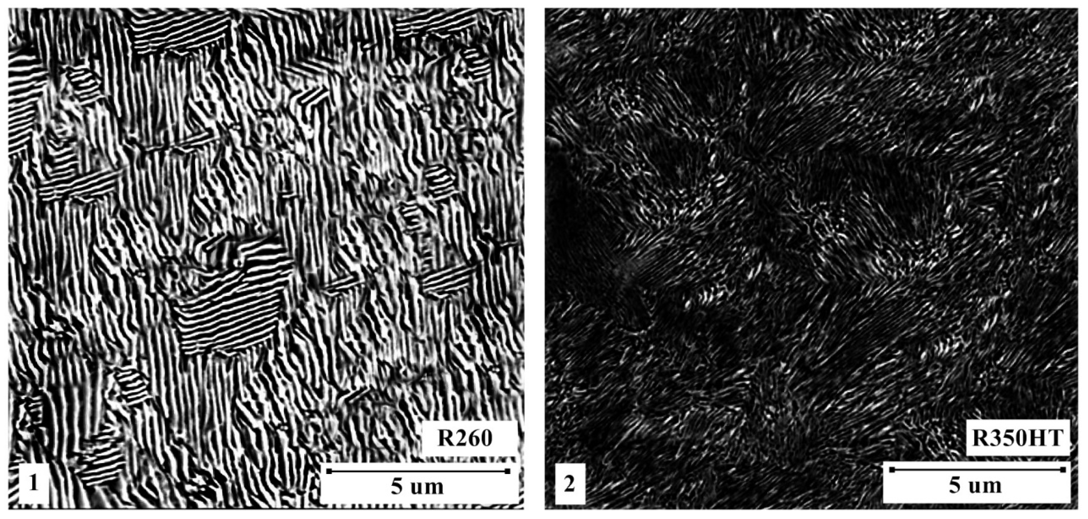
| Steel | Interlamellar Spacing, nm | Hardness, HV 10 |
|---|---|---|
| R260 | 119 ± 10 | 370 ± 6 |
| R350HT | 335 ± 21 | 295 ± 6 |
| Scale Classification | Purpose of the Rail/Dimension Deviations ∆f, mm | |||
|---|---|---|---|---|
| Main Tracks | Other Tracks | |||
| Concavity | Convexity | Concavity | Convexity | |
| Okay | ∆f ≤ 0.3 | ∆f = 0.0 | ∆f ≤ 0.5 | ∆f ≤ 0.5 |
| For repair | 0.3 < ∆f ≤ 0.6 | 0.0 < ∆f ≤ 0.3 | 0.5 < ∆f ≤ 0.8 | 0.5 < ∆f ≤ 0.8 |
| To be cut out | ∆f > 0.6 | ∆f > 0.3 | ∆f > 0.8 | ∆f > 0.8 |
| Scale Classification | Purpose of the Rail/Dimension Deviations ∆f, mm | |||||
|---|---|---|---|---|---|---|
| Main Tracks | Other Tracks | |||||
| V > 160 km/h | V ≤ 160 km/h | |||||
| Concavity | Convexity | Concavity | Convexity | Concavity | Convexity | |
| Okay | ∆f = 0.0 | ∆f ≤ 0.3 | ∆f ≤ 0.1 | ∆f ≤ 0.3 | ∆f ≤ 0.5 | ∆f ≤ 0.5 |
| For repair | 0.0 < ∆f ≤ 0.2 | 0.3 < ∆f ≤ 0.5 | 0.1 < ∆f ≤ 0.3 | 0.3 < ∆f ≤ 0.5 | 0.5 < ∆f ≤ 0.8 | 0.5 < ∆f ≤ 1.0 |
| To be cut out | ∆f > 0.2 | ∆f > 0.5 | ∆f > 0.3 | ∆f > 0.5 | ∆f > 0.8 | ∆f > 1.0 |
| Type of Rail Joint | Bending Force, kN | Displacement, mm | ||
|---|---|---|---|---|
| Requirements | Findings | Requirements | Findings | |
| Welded joint according to PN-EN 14587-1:2007 | >1600 | 1638 | >20.0 | 31 |
| 1695 | 26 | |||
| 1752 | 38 | |||
| 1746 | 28 | |||
| 1789 | 29 | |||
Disclaimer/Publisher’s Note: The statements, opinions and data contained in all publications are solely those of the individual author(s) and contributor(s) and not of MDPI and/or the editor(s). MDPI and/or the editor(s) disclaim responsibility for any injury to people or property resulting from any ideas, methods, instructions or products referred to in the content. |
© 2023 by the authors. Licensee MDPI, Basel, Switzerland. This article is an open access article distributed under the terms and conditions of the Creative Commons Attribution (CC BY) license (https://creativecommons.org/licenses/by/4.0/).
Share and Cite
Wróblewski, P.; Niekurzak, M.; Kachel, S. Experimental Studies of Welded Joints in Structures Subject to High Impact Vibrations Using Destructive and Non-Destructive Methods. Materials 2023, 16, 1886. https://doi.org/10.3390/ma16051886
Wróblewski P, Niekurzak M, Kachel S. Experimental Studies of Welded Joints in Structures Subject to High Impact Vibrations Using Destructive and Non-Destructive Methods. Materials. 2023; 16(5):1886. https://doi.org/10.3390/ma16051886
Chicago/Turabian StyleWróblewski, Piotr, Mariusz Niekurzak, and Stanisław Kachel. 2023. "Experimental Studies of Welded Joints in Structures Subject to High Impact Vibrations Using Destructive and Non-Destructive Methods" Materials 16, no. 5: 1886. https://doi.org/10.3390/ma16051886
APA StyleWróblewski, P., Niekurzak, M., & Kachel, S. (2023). Experimental Studies of Welded Joints in Structures Subject to High Impact Vibrations Using Destructive and Non-Destructive Methods. Materials, 16(5), 1886. https://doi.org/10.3390/ma16051886