
A Low-Cost Silica Fiber/Epoxy Composite with Excellent Dielectric Properties, and Good Mechanical and Thermal Stability


Abstract
:1. Introduction
2. Materials and Methods
2.1. Materials
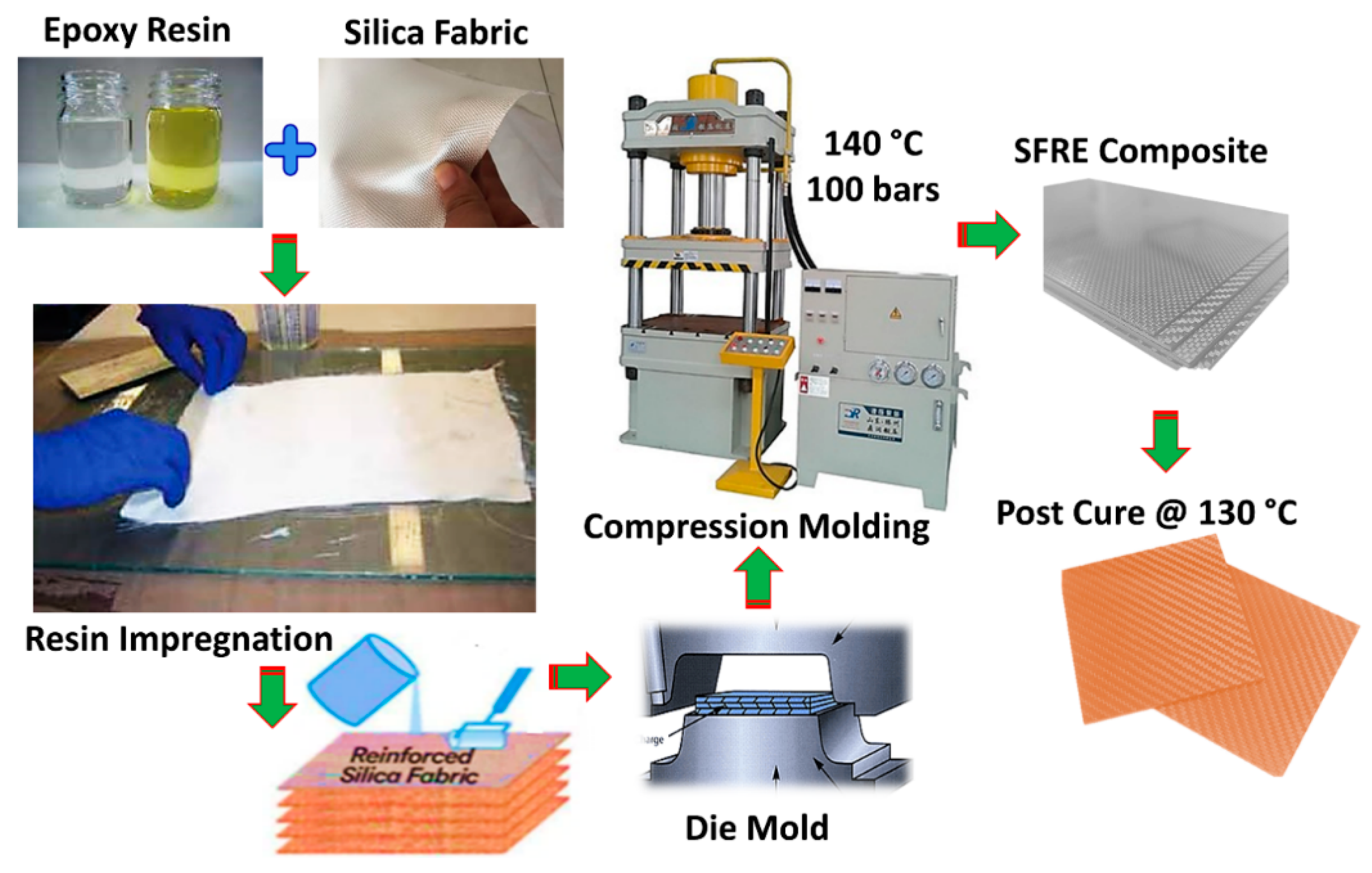
2.2. Fabrication of Composite
2.3. Characterization
3. Results and Discussion
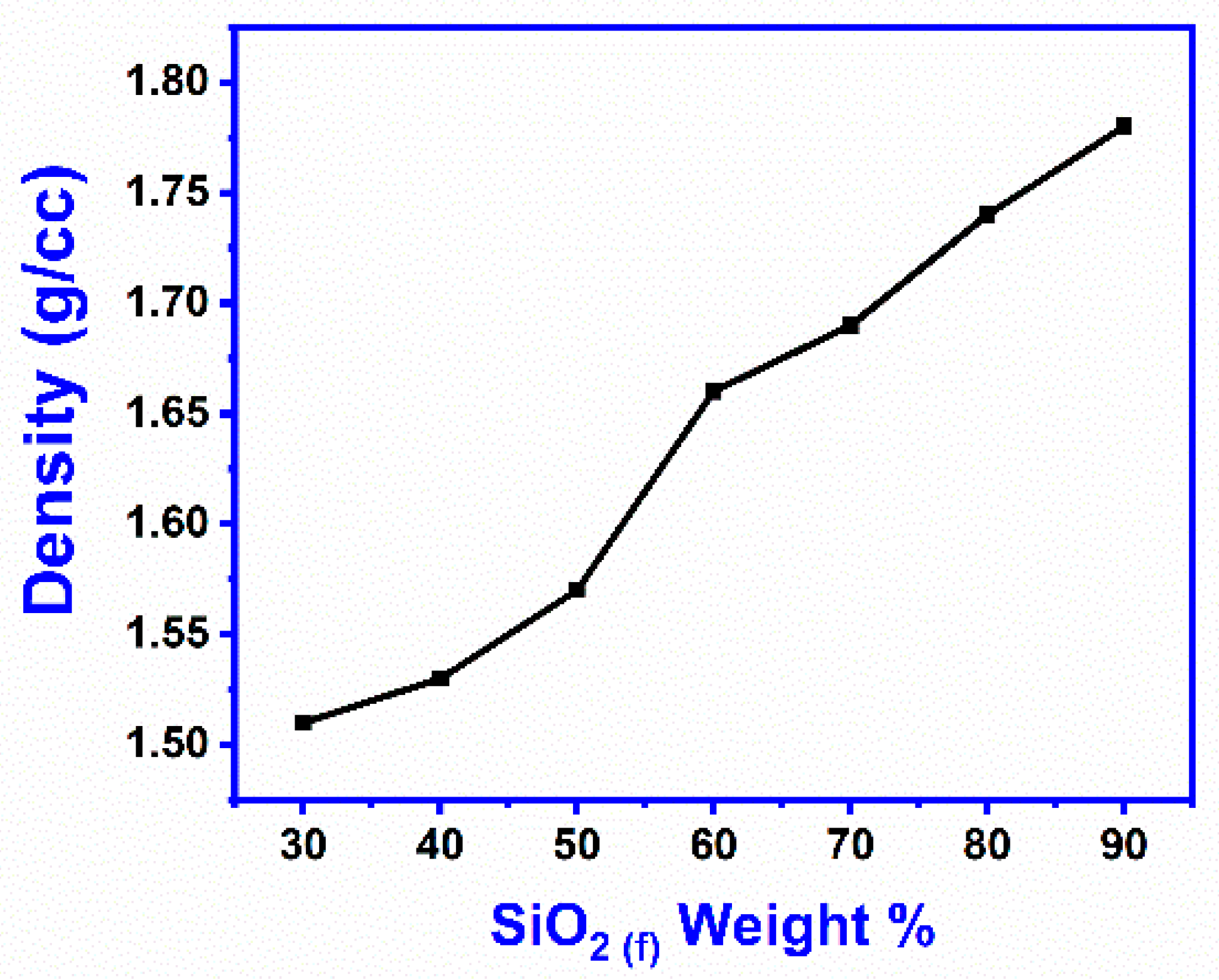
3.1. Density
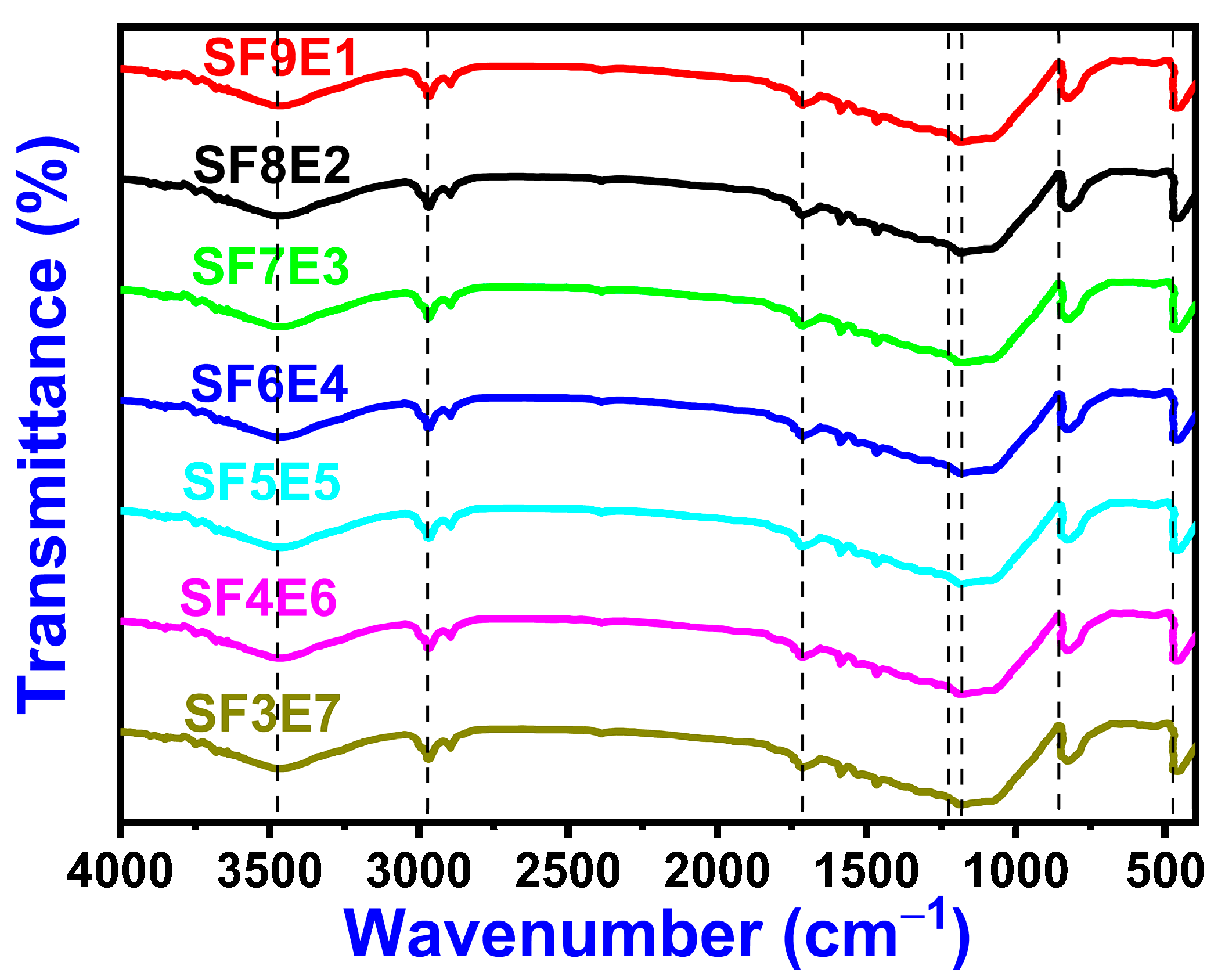
3.2. FTIR
3.3. X-ray Diffraction (XRD)
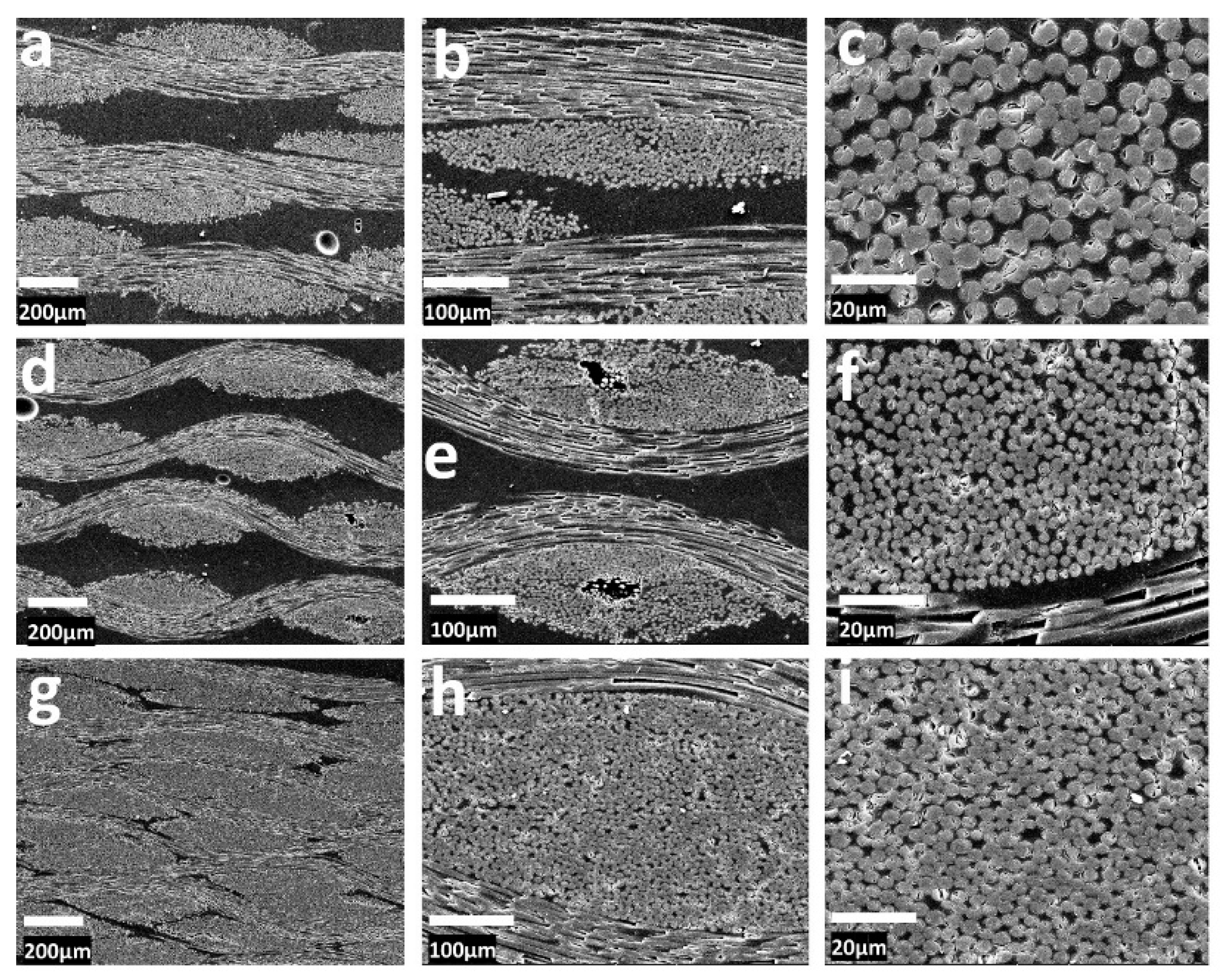
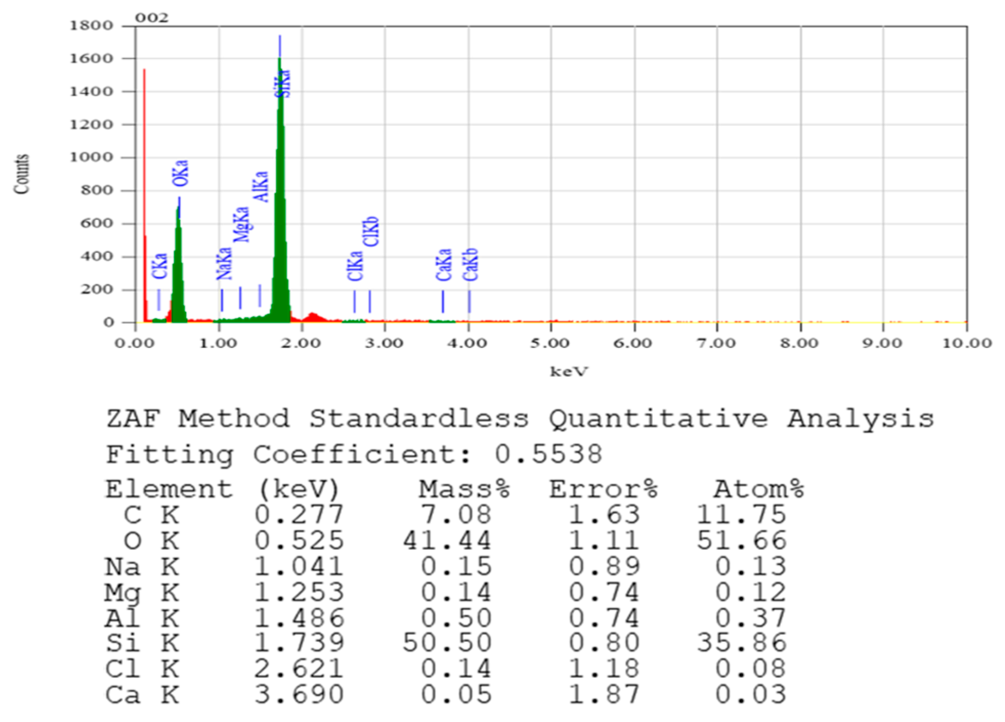
3.4. Morphology
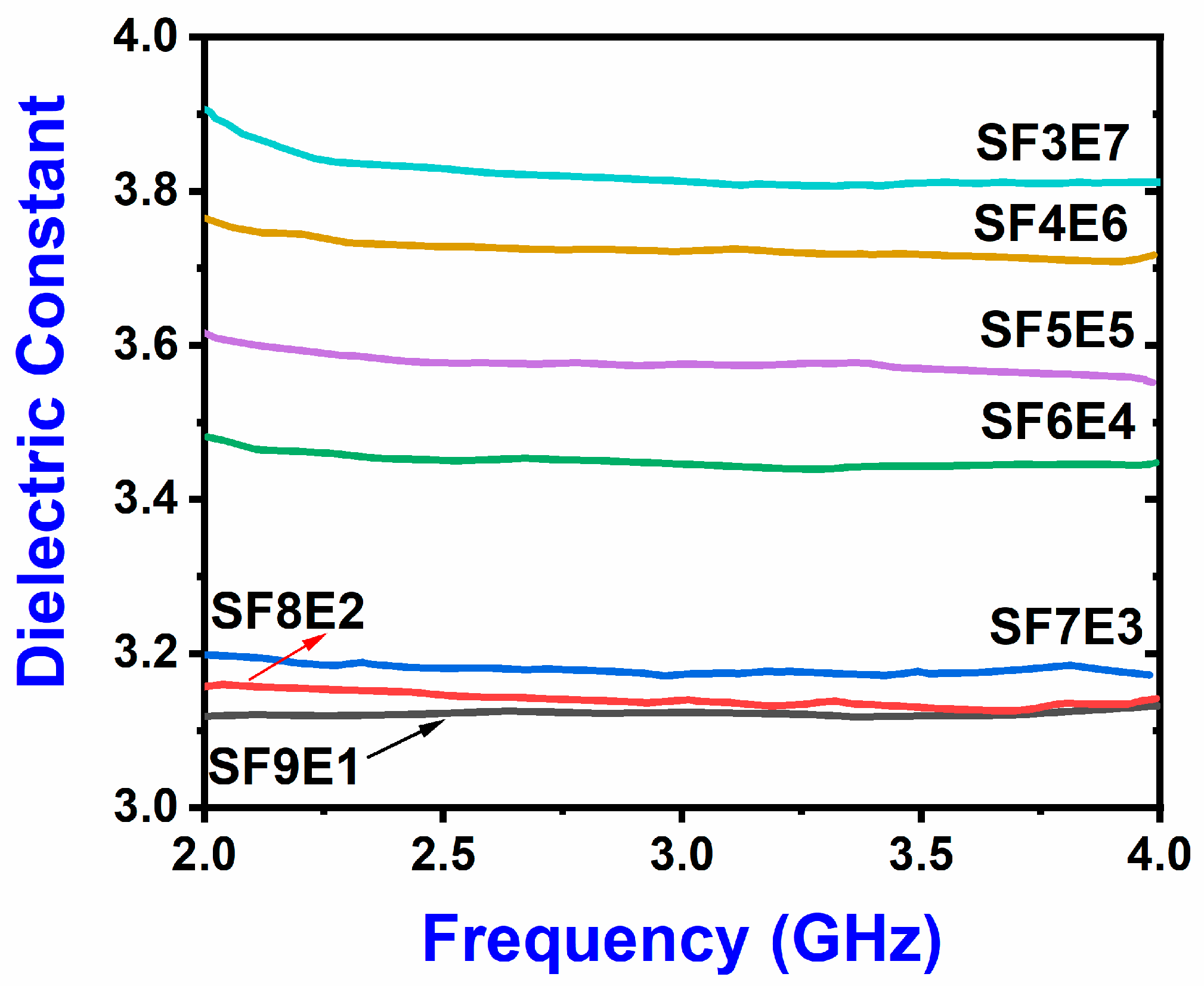
3.5. Dielectric Constant
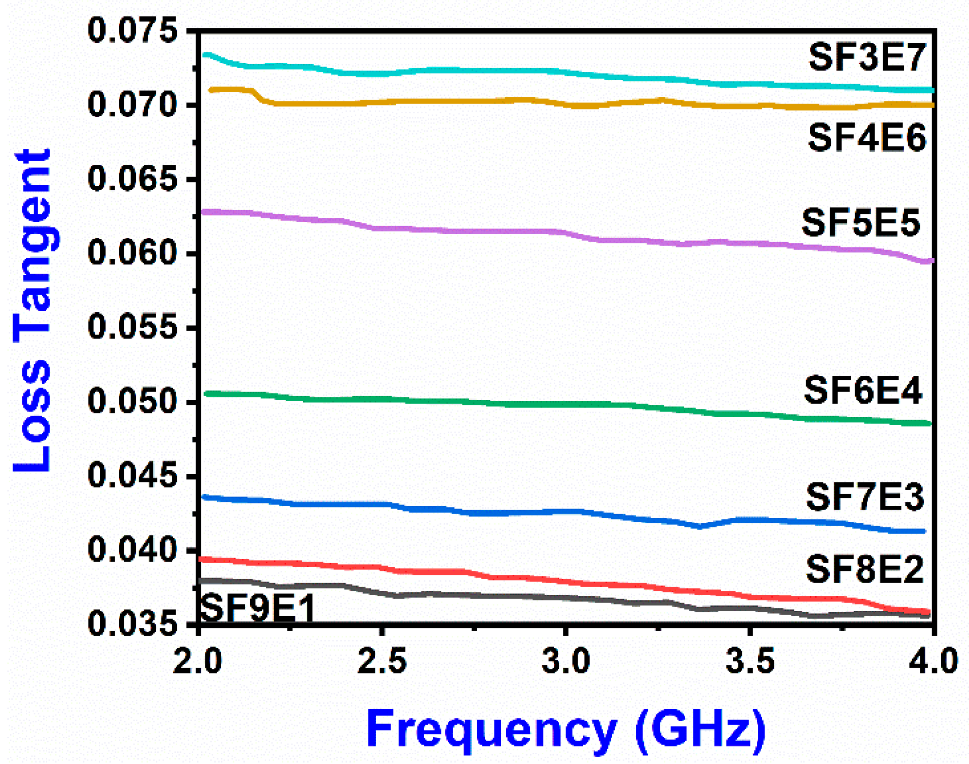
3.6. Dilecetric Loss Tangent
3.7. Electrical Conductivity
- ω = frequency
- ε0 = 8.85 × 10⁻¹²
- tan δ = ε′′/ε′
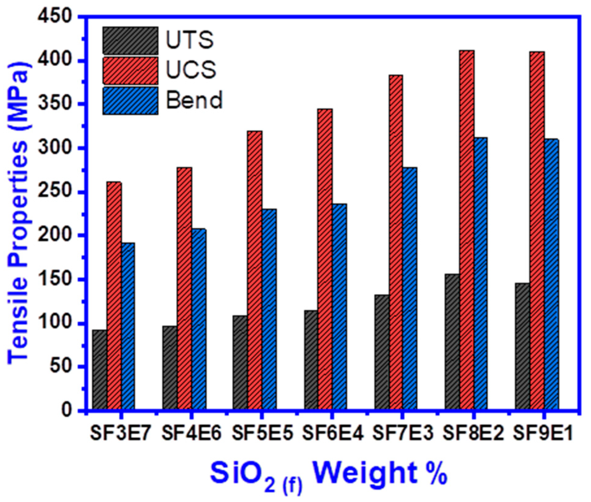
3.8. Tensile Properties
3.8.1. Ultimate Tensile Strength (UTS)
3.8.2. Ultimate Compression Strength (UCS)
3.8.3. Flexural Strength
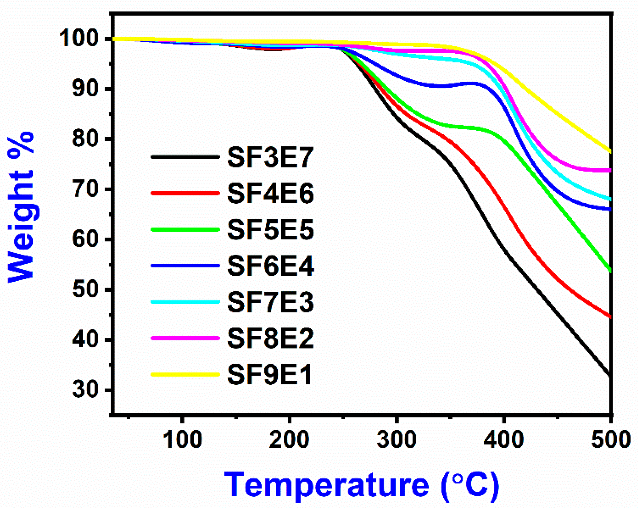
3.9. Thermo-Gravimetric Analysis
3.10. Moisture Absorption
3.11. Property Comparison of Glass Fiber/Epoxy Composite
4. Conclusions
Author Contributions
Funding
Institutional Review Board Statement
Informed Consent Statement
Data Availability Statement
Acknowledgments
Conflicts of Interest
References
- Yao, L.; Wang, X.; Liang, F.; Wu, R.; Hu, B.; Feng, Y.; Qiu, Y. Modeling, and experimental verification of dielectric constants for three-dimensional woven composites. Compos. Sci. Technol. 2008, 68, 1794–1799. [Google Scholar] [CrossRef]
- Yang, X.; Qing, W.; Zhi-Hang, P.; Feng, C. High-temperature properties of 2.5D SiO2f/SiO2 composites by sol–gel. Ceram. Int. 2016, 42, 12802–12806. [Google Scholar] [CrossRef]
- Qi, G.; Zhang, C.; Hu, H.; Cao, F.; Wang, S.; Cao, Y.; Jiang, Y. Preparation of three-dimensional silica fiber reinforced silicon nitride composites using perhydropolysilazane as precursor. Mater. Lett. 2005, 59, 3256–3258. [Google Scholar] [CrossRef]
- Manocha, L.; Panchal, C.; Manocha, S. Silica/Silica Composites Through Electrophoretic Infiltration—Effect of Processing Conditions on Densification of Composites. Sci. Eng. Compos. Mater. 2000, 9, 219–230. [Google Scholar] [CrossRef]
- Sathishkumar, T.P.; Satheeshkumar, S.; Naveen, J. Glass fiber-reinforced polymer composites—A review. J. Reinf. Plast. Compos. 2014, 33, 1258–1275. [Google Scholar] [CrossRef]
- Kistaiah, N.; Kiran, C.U.; Reddy, G.R.; Rao, M.S. Mechanical characterization of hybrid composites: A review. J. Reinf. Plast. Compos. 2014, 33, 1364–1372. [Google Scholar] [CrossRef]
- Rutz, B.H.; Berg, J.C. Electrostatic deposition of silica nanoparticles between E-glass fibers and an epoxy resin. J. Appl. Polym. Sci. 2015, 132, 41516. [Google Scholar] [CrossRef]
- Godara, A.; Gorbatikh, L.; Kalinka, G.; Warrier, A.; Rochez, O.; Mezzo, L.; Luizi, F.; van Vuure, A.; Lomov, S.; Verpoest, I. Interfacial shear strength of a glass fiber/epoxy bonding in composites modified with carbon nanotubes. Compos. Sci. Technol. 2010, 70, 1346–1352. [Google Scholar] [CrossRef]
- Mäder, E.; Gao, S.-L.; Plonka, R.; Wang, J. Investigation on adhesion, interphases, and failure behaviour of cyclic butylene terephthalate (CBT®)/glass fiber composites. Compos. Sci. Technol. 2007, 67, 3140–3150. [Google Scholar] [CrossRef]
- Ramajo, L.; Reboredo, M.; Castro, M. Dielectric response and relaxation phenomena in composites of epoxy resin with BaTiO3 particles. Compos. Part A Appl. Sci. Manuf. 2005, 36, 1267–1274. [Google Scholar] [CrossRef]
- Starke, T.K.H.; Johnston, C.; Hill, S.; Dobson, P.; Grant, P. The effect of inhomogeneities in particle distribution on the dielectric properties of composite films. J. Phys. D Appl. Phys. 2006, 39, 1305–1311. [Google Scholar] [CrossRef]
- Kafi, A.; Abedin, M.Z.; Beg, M.D.H.; Pickering, K.; Khan, M.A. Study on the Mechanical Properties of Jute/Glass Fiber-reinforced Unsaturated Polyester Hybrid Composites: Effect of Surface Modification by Ultraviolet Radiation. J. Reinf. Plast. Compos. 2006, 25, 575–588. [Google Scholar] [CrossRef]
- Anuar, H.; Ahmad, S.H.; Rasid, R.; Daud, N.S.N. Tensile and Impact Properties of Thermoplastic Natural Rubber Reinforced Short Glass Fiber and Empty Fruit Bunch Hybrid Composites. Polym. Technol. Eng. 2006, 45, 1059–1063. [Google Scholar] [CrossRef]
- Xie, H.-Q.; Zhang, S.; Xie, D. An efficient way to improve the mechanical properties of polypropylene/short glass fiber composites. J. Appl. Polym. Sci. 2005, 96, 1414–1420. [Google Scholar] [CrossRef]
- Fu, X.; Guo, Y.; Du, Q.; Guan, L.; He, S. Improved dielectric stability of epoxy composites with ultralow boron nitride loading. RSC Adv. 2019, 9, 4344. [Google Scholar] [CrossRef]
- Kchaou, B.; Turki, C.; Salvia, M.; Fakhfakh, Z.; Tréheux, D. Role of fibre–matrix interface and fibre direction on dielectric behaviour of epoxy composites. Compos. Sci. Technol. 2004, 64, 1467–1475. [Google Scholar] [CrossRef]
- Sakthidharan, C.P.; Sundararajan, P.R.; Sarojadevi, M. Thermal and mechanical properties of epoxy blends with a dicyanate ester containing a quinoline moiety. New J. Chem. 2018, 42, 11202–11212. [Google Scholar] [CrossRef]
- Li, X.; Zhang, L.; Yin, X. Fabrication and Properties of Porous Si3N4 Ceramic with High Porosity. J. Mater. Sci. Technol. 2012, 28, 1151–1156. [Google Scholar] [CrossRef]
- Ding, S.; Zeng, Y.-P.; Jiang, D. Oxidation bonding of porous silicon nitride ceramics with high strength and low dielectric constant. Mater. Lett. 2007, 61, 2277–2280. [Google Scholar] [CrossRef]
- Li, B.; Liu, K.; Zhang, C.-R.; Wang, S.-Q. Fabrication and properties of borazine derived boron nitride bonded porous silicon aluminum oxynitride wave-transparent composite. J. Eur. Ceram. Soc. 2014, 34, 3591–3595. [Google Scholar] [CrossRef]
- Li, W.; Huang, W.; Kang, Y.; Gong, Y.; Ying, Y.; Yu, J.; Zheng, J.; Qiao, L.; Che, S. Fabrication and investigations of G-POSS/cyanate ester resin composites reinforced by silane-treated silica fibers. Compos. Sci. Technol. 2019, 173, 7–14. [Google Scholar] [CrossRef]
- Wang, H.; Yu, J.; Zhang, J.; Zhang, D. Preparation and properties of pressureless-sintered porous Si3N4. J. Mater. Sci. 2010, 45, 3671–3676. [Google Scholar] [CrossRef]
- Zhang, Y.; Jia, C. High-performance cyanate ester composites with plasma-synthesized MgSiO3-SiO2-hBN powders for thermally conductive and dielectric properties. Ceram. Int. 2019, 45, 6491–6498. [Google Scholar] [CrossRef]
- Liu, Z.; Zhang, J.; Tang, L.; Zhou, Y.; Lin, Y.; Wang, R.; Kong, J.; Tang, Y.; Gu, J. Improved wave-transparent performances and enhanced mechanical properties for fluoride-containing PBO precursor modified cyanate ester resins and their PBO fibers/cyanate ester composites. Compos. Part B Eng. 2019, 178, 107466. [Google Scholar] [CrossRef]
- Polydoropoulou, P.; Katsiropoulos, C.; Pantelakis, S.; Raimondo, M.; Guadagno, L. A critical assessment of multifunctional polymers with regard to their potential use in structural applications. Compos. Part B Eng. 2019, 157, 150–162. [Google Scholar] [CrossRef]
- Li, X.; Ling, Y.; Zhang, G.; Yin, Y.; Dai, Y.; Zhang, C.; Luo, J. Preparation and tribological properties of solid-liquid synergetic self-lubricating PTFE/SiO2/PAO6 composites. Compos. Part B Eng. 2020, 196, 108133. [Google Scholar] [CrossRef]
- Ahmad, I.; Baharum, A.; Abdullah, I. Effect of Extrusion Rate and Fiber Loading on Mechanical Properties of Twaron Fiber-thermoplastic Natural Rubber (TPNR) Composites. J. Reinf. Plast. Compos. 2006, 25, 957–965. [Google Scholar] [CrossRef]
- Pi, Z.; Xiao, H.; Liu, R.; Liu, M.; Li, H. Effects of brass coating and nano-SiO2 coating on steel fiber–matrix interfacial properties of cement-based composite. Compos. Part B Eng. 2020, 189, 107904. [Google Scholar] [CrossRef]
- Khoathane, M.; Vorster, O.; Sadiku, E. Hemp Fiber-Reinforced 1-Pentene/Polypropylene Copolymer: The Effect of Fiber Loading on the Mechanical and Thermal Characteristics of the Composites. J. Reinf. Plast. Compos. 2008, 27, 1533–1544. [Google Scholar] [CrossRef]
- Tang, L.; Zhang, J.; Tang, Y.; Kong, J.; Liu, T.; Gu, J. Polymer matrix wave-transparent composites: A review. J. Mater. Sci. Technol. 2021, 75, 225–251. [Google Scholar] [CrossRef]
- Lan, T.; Liang, Y.; Lu, Z.; Li, N.; Pei, Y. Study on the Effect of Fabric Parameters on the properties of Wave-Transparent Composites. J. Mater. Sci. Technol. 2021, 75, 225–251. [Google Scholar] [CrossRef]
- Khatavkar, N.; Balasubramanian, K. Composite materials for supersonic aircraft radomes with ameliorated radio frequency transmission-a review. RSC Adv. 2016, 6, 6709. [Google Scholar] [CrossRef]
- Wallenberger, F.T. Chapter 4—Continuous Melt Spinning Processes. In Advanced Inorganic Fibers: Processes, Structures, Properties, Applications; Kluwer Academic Publishers: Amsterdam, The Netherlands, 1999; pp. 81–122. Available online: https://www.springer.com/gp/book/9780412607905 (accessed on 22 September 2022).
- Wallenberger, F.T. Structural Silicate and Silica Glass Fibers. In Advanced Inorganic Fibers; Springer: Boston, MA, USA, 2000; Volume 6, pp. 129–168. [Google Scholar] [CrossRef]
- Wallenberger, F.T. Commercial and Experimental Glass Fibers, Chapter 1. In Fiberglass and Glass Technology; Springer: Boston, MA, USA, 2010. [Google Scholar]
- Nazir, T.; Afzal, A.; Siddiqi, H.M.; Saeed, S.; Dumon, M. The influence of temperature and interface strength on the microstructure and performance of sol–gel silica–epoxy nanocomposites. Polym. Bull. 2011, 67, 1539–1551. [Google Scholar] [CrossRef]
- Sebastian, M.T. Dielectric Materials for Wireless Communication; Elsevier: Amsterdam, The Netherlands, 2010. [Google Scholar]
- Kozakoff, D.J. Analysis of Radome-Enclosed Antennas, 2nd ed.; Artech House: Norwood, MA, USA, 2010. [Google Scholar]
- Peters, S.T. Handbook of Composite, 2nd ed.; Springer: Berlin/Heidelberg, Germany, 1997. [Google Scholar]
- Miracle, D.B.; Donaldson, S.L. ASM Handbook; ASM International: Almere, The Netherlands, 2001; Volume 21, pp. 126–131. [Google Scholar]
- Khajeh, A.; Mustapha, F.; Sultan, M.T.H.; Bánhegyi, G.; Karácsony, Z.; Baranyai, V. Effect of Thermo-oxidative Aging on the Durability of Glass Fiber-Reinforced Epoxy. Adv. Mater. Sci. Eng. 2015, 354–372. [Google Scholar]
- Dong, Y.; Zhu, Y.; Zhao, Y.; Liu, F.; Wang, E.; Fu, Y. Enhance interfacial properties of glass fiber/epoxy composites with environment-friendly water-based hybrid sizing agent. Compos. Part A Appl. Sci. Manuf. 2017, 102, 357–367. [Google Scholar] [CrossRef]
- Yang, X.; Li, B.; Li, D.; Shao, C.; Zhang, C. High-temperature properties and interface evolution of silicon nitride fiber reinforced silica matrix wave-transparent composite materials. J. Eur. Ceram. Soc. 2019, 39, 240–248. [Google Scholar] [CrossRef]
- Zou, C.; Li, B.; Meng, X.; Liu, K.; Yang, X.; Li, D.; Wang, S. Ablation behavior and mechanism of SiO2f/SiO2, SiO2f/BN, and Si3N4f/BN radar wave transparent composites. Corros. Sci. 2018, 139, 243–254. [Google Scholar] [CrossRef]
- Yang, X.; Li, B.; Li, D.; Shao, C.; Zhang, C.; Zou, C.; Liu, K. Fabrication and oxidation resistance of silicon nitride fiber reinforced silica matrix wave-transparent composites. J. Mater. Sci. Technol. 2019, 35, 2761–2766. [Google Scholar] [CrossRef]
- Youssef, G.; Newacheck, S.; Huynh, N.; Gamez, C. Multiscale Characterization of E-Glass/Epoxy Composite Exposed to Extreme Environmental Conditions. J. Compos. Sci. 2021, 5, 80. [Google Scholar] [CrossRef]
- Patsidis, A.C.; Psarras, G.C. Chapter 11: Dielectric and Conductivity Studies of Epoxy Composites. In Epoxy Composites: Fabrication, Characterization and Applications; Wiley-VCH: Weinheim, Germany, 2021; pp. 299–348. [Google Scholar] [CrossRef]
- Manju, M.; Vignesh, S.; Nikhil, K.; Sharaj, A.; Murthy, M. Electrical Conductivity Studies of Glass Fiber Reinforced Polymer Composites. Mater. Today Proc. 2018, 5, 3229–3236. [Google Scholar] [CrossRef]


| Parameter | Cyanate Ester Resin | DGEBA Resin | Polyester Resin | Bismaleimide Resin |
|---|---|---|---|---|
| Density (g/cc) | 1.17 | 1.30 | 1.29 | 1.30 |
| εr | 2.8–3.2 | 3.7–4.1 | 2.8–4.0 | 3.1–3.5 |
| δ | 0.002–0.008 | 0.018–0.020 | 0.006–0.026 | 0.005–0.020 |
| Flexural strength (MPa) | 80 | 97 | 85 | 150 |
| Cost ratio (approx) | 1:1 | 1:0.2 | 1:0.15 | 1:0.9 |
| Parameter | Quartz-Glass | High-Silica Glass | D-Glass | E-Glass |
|---|---|---|---|---|
| SiO2% | 99.99 | 95–98 | 72–75 | 52–57 |
| Density | 2.20 | 2.15 | 2.6 | 2.54 |
| UTS (GPa) | 1.70 | 1.8 | 2.4 | 3.75 |
| εr | 3.78 | 4.1 | 4.0 | 6.13 |
| δ | 0.0002 | 0.020 | 0.0025 | 0.0038 |
| Cost ratio (approx) | 1:3 | 1:1 | 1:2 | 1:1.2 |
| Fabric Drying | Resin (R: H) | Degassing (5 min) | Soaking | Hot Pressing | Curing | Post Curing |
|---|---|---|---|---|---|---|
| 120 °C | 1.6:1 | 5 × 10⁻³ mbar | 20 min | 100 bar | 140@4 h | 130@3 h |
| Identity | SF3E7 | SF4E6 | SF5E5 | SF6E4 | SF7E3 | SF8E2 | SF9E1 |
|---|---|---|---|---|---|---|---|
| Silica% | 30 | 40 | 50 | 60 | 70 | 80 | 90 |
| Epoxy% | 70 | 60 | 50 | 40 | 30 | 20 | 10 |
| Parameter | D-GFs | E-GFs | Quartz-GFs | High-Silica-GFs |
|---|---|---|---|---|
| SiO2% (wt.) | ≥72 | ≥54 | ≥99.9 | ≥96.5 |
| Density (g/cc) | ≤1.78 | ≤1.74 | ≤1.73 | ≤1.76 |
| XRD (2ϴ) range | 20°~22° | 20°~22° | 20°~22° | 20°~22° |
| ε | 2.8–3.4 | 5.4–6 | 2.95~3.3 | 3.17~3.82 |
| δ | 0.001~0.01 | 0.06~0.08 | 0.001~0.005 | 0.07~0.036 |
| Compression (Mpa) | 461.63 | 725.61 | 442.2 | 382.8~405.1 |
| Tensile Strength (Mpa) | 144.35 | 198.49 | 103.91 | 132.3~155.7 |
| Flexural Strength(Mpa) | 141.6 | 189.6 | 113.6 | 277.7 to 311.9 |
| % Weight loss (TGA) | 25.2 | 21.3 | 18.9 | 26.5 |
| Moisture absorption% | 1.3 | 2.3 | 1.1 | 1.1~1.3 |
| Cost Ratio | Highest | Medium | High | Low |
| References | [33,34,35,36,37,38,39,40,41,42,45,46,47,48] | This work | ||
Disclaimer/Publisher’s Note: The statements, opinions and data contained in all publications are solely those of the individual author(s) and contributor(s) and not of MDPI and/or the editor(s). MDPI and/or the editor(s) disclaim responsibility for any injury to people or property resulting from any ideas, methods, instructions or products referred to in the content. |
© 2023 by the authors. Licensee MDPI, Basel, Switzerland. This article is an open access article distributed under the terms and conditions of the Creative Commons Attribution (CC BY) license (https://creativecommons.org/licenses/by/4.0/).
Share and Cite
Haider, I.; Gul, I.H.; Umer, M.A.; Baig, M.M. A Low-Cost Silica Fiber/Epoxy Composite with Excellent Dielectric Properties, and Good Mechanical and Thermal Stability. Materials 2023, 16, 7410. https://doi.org/10.3390/ma16237410
Haider I, Gul IH, Umer MA, Baig MM. A Low-Cost Silica Fiber/Epoxy Composite with Excellent Dielectric Properties, and Good Mechanical and Thermal Stability. Materials. 2023; 16(23):7410. https://doi.org/10.3390/ma16237410
Chicago/Turabian StyleHaider, Imran, Iftikhar Hussain Gul, Malik Adeel Umer, and Mutawara Mahmood Baig. 2023. "A Low-Cost Silica Fiber/Epoxy Composite with Excellent Dielectric Properties, and Good Mechanical and Thermal Stability" Materials 16, no. 23: 7410. https://doi.org/10.3390/ma16237410
APA StyleHaider, I., Gul, I. H., Umer, M. A., & Baig, M. M. (2023). A Low-Cost Silica Fiber/Epoxy Composite with Excellent Dielectric Properties, and Good Mechanical and Thermal Stability. Materials, 16(23), 7410. https://doi.org/10.3390/ma16237410