
Dual-Period Polarization-Dependent Diffraction Gratings Based on a Polymer-Stabilized Liquid Crystal


Abstract
:
1. Introduction
2. Materials and Methods
2.1. Material Preparation
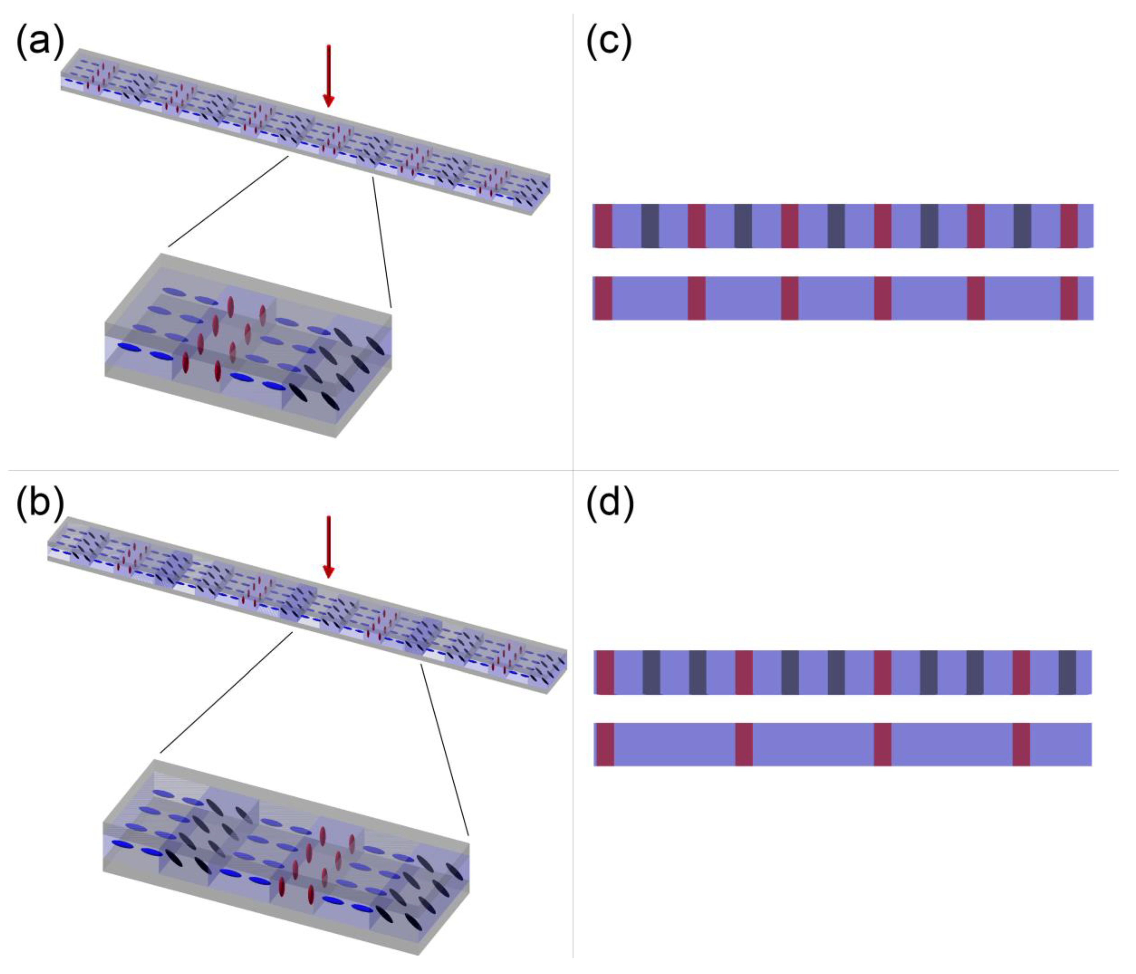
2.2. Design and Fabrication
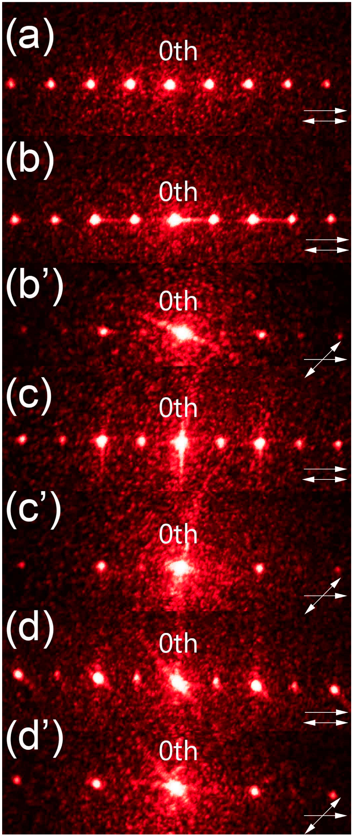
2.3. Analysis of Diffraction Patterns
3. Results and Discussion
3.1. Diffraction Gratings with Double Period Change
3.2. Diffraction Gratings with Triple Period Change
4. Conclusions
Author Contributions
Funding
Institutional Review Board Statement
Informed Consent Statement
Data Availability Statement
Conflicts of Interest
References
- Zhang, H.; Miao, Z.; Shen, W. Development of Polymer-Dispersed Liquid Crystals: From Mode Innovation to Applications. Compos. Part A Appl. Sci. Manuf. 2022, 163, 107234. [Google Scholar] [CrossRef]
- Ye, Y.; Guo, L.; Zhong, T. A Review of Developments in Polymer Stabilized Liquid Crystals. Polymers 2023, 15, 2962. [Google Scholar] [CrossRef] [PubMed]
- Yan, J.; Li, Y.; Wu, S.-T. High-Efficiency and Fast-Response Tunable Phase Grating Using a Blue Phase Liquid Crystal. Opt. Lett. 2011, 36, 1404–1406. [Google Scholar] [CrossRef]
- Chychłowski, M.S.; Kajkowska, M.; Jankiewicz, B.; Bartosewicz, B.; Woliński, T.R.; Lesiak, P. Photopolymerization of 1D Photonic Structures Induced by Nematic–Isotropic Phase Transition in Liquid Crystal. Soft Matter 2023, 19, 3398–3404. [Google Scholar] [CrossRef] [PubMed]
- Ge, Z.; Gauza, S.; Jiao, M.; Xianyu, H.; Wu, S.-T. Electro-Optics of Polymer-Stabilized Blue Phase Liquid Crystal Displays. Appl. Phys. Lett. 2009, 94, 101104. [Google Scholar] [CrossRef]
- Ono, H.; Emoto, A.; Takahashi, F.; Kawatsuki, N.; Hasegawa, T. Highly Stable Polarization Gratings in Photocrosslinkable Polymer Liquid Crystals. J. Appl. Phys. 2003, 94, 1298–1303. [Google Scholar] [CrossRef]
- Kajkowska, M.; Chychłowski, M.; Lesiak, P. Influence of Photopolymerization on Propagation Properties of Photonic Crystal Fiber Infiltrated with Liquid Crystal Mixture. Photonics Lett. Pol. 2022, 14, 68–70. [Google Scholar] [CrossRef]
- Rutkowska, K.A.; Chychłowski, M. Methods for Polymer-Stabilization of Molecular Orientation in LC-Waveguiding Structures. Photonics Lett. Pol. 2018, 10, 11–13. [Google Scholar] [CrossRef]
- Chychłowski, M.S.; Ertman, S.; Rutkowska, K.; Strzeżysz, O.; Dąbrowski, R.; Woliński, T.R. Locally-Induced Permanent Birefringence by Polymer-Stabilization of Liquid Crystal in Cells and Photonic Crystal Fibers. Opto-Electron. Rev. 2018, 26, 242–246. [Google Scholar] [CrossRef]
- Rutkowska, K.A.; Chychłowski, M.; Kwaśny, M.; Ostromęcka, I.; Piłka, J.; Laudyn, U.A. Light Propagation in Periodic Photonic Structures Formed by Photo-Orientation and Photo-Polymerization of Nematic Liquid Crystals. Opto-Electron. Rev. 2017, 25, 118–126. [Google Scholar] [CrossRef]
- Wang, J.; McGinty, C.; Reich, R.; Finnemeyer, V.; Clark, H.; Berry, S.; Bos, P. Process for a Reactive Monomer Alignment Layer for Liquid Crystals Formed on an Azodye Sublayer. Materials 2018, 11, 1195. [Google Scholar] [CrossRef]
- Lee, S.N.; Chien, L.-C.; Sprunt, S. Polymer-Stabilized Diffraction Gratings from Cholesteric Liquid Crystals. SID Symp. Dig. Tech. Pap. 1998, 29, 834–837. [Google Scholar] [CrossRef]
- Bronnikov, S.; Kostromin, S.; Zuev, V. Polymer-Dispersed Liquid Crystals: Progress in Preparation, Investigation, and Application. J. Macromol. Sci. Part B 2013, 52, 1718–1735. [Google Scholar] [CrossRef]
- Ren, H.; Fan, Y.-H.; Lin, Y.-H.; Wu, S.-T. Tunable-Focus Microlens Arrays Using Nanosized Polymer-Dispersed Liquid Crystal Droplets. Opt. Commun. 2005, 247, 101–106. [Google Scholar] [CrossRef]
- Presnyakov, V.V.; Galstian, T.V. Electrically Tunable Polymer Stabilized Liquid-Crystal Lens. J. Appl. Phys. 2005, 97, 103101. [Google Scholar] [CrossRef]
- Hsu, C.J.; Sheu, C.R. Using Photopolymerization to Achieve Tunable Liquid Crystal Lenses with Coaxial Bifocals. Opt. Express 2012, 20, 4738–4746. [Google Scholar] [CrossRef] [PubMed]
- Fan, Y.-H.; Ren, H.; Wu, S.-T. Switchable Fresnel Lens Using Polymer-Stabilized Liquid Crystals. Opt. Express 2003, 11, 3080–3086. [Google Scholar] [CrossRef]
- Luo, W.; Ni, M.; Zhou, X.; Peng, H.; Xie, X. Holographic Polymer Nanocomposites with Both High Diffraction Efficiency and Bright Upconversion Emission by Incorporating Liquid Crystals and Core-Shell Structured Upconversion Nanoparticles. Compos. Part B Eng. 2020, 199, 108290. [Google Scholar] [CrossRef]
- Wang, K.; Zheng, J.; Gui, K.; Li, D.; Zhuang, S. Improvement on the Performance of Holographic Polymer-Dispersed Liquid Crystal Gratings with Surface Plasmon Resonance of Ag and Au Nanoparticles. Plasmonics 2015, 10, 383–389. [Google Scholar] [CrossRef]
- Wang, K.; Zheng, J.; Liu, Y.; Gao, H.; Zhuang, S. Electrically Tunable Two-Dimensional Holographic Polymer-Dispersed Liquid Crystal Grating with Variable Period. Opt. Commun. 2017, 392, 128–134. [Google Scholar] [CrossRef]
- Gao, L.; Zheng, Z.-Z.; Zhu, J.-L.; Han, W.-M.; Sun, Y.-B. Dual-Period Tunable Phase Grating Based on a Single in-Plane Switching. Opt. Lett. 2016, 41, 3775–3778. [Google Scholar] [CrossRef] [PubMed]
- Yan, J.; Xing, Y.; Li, Q. Dual-Period Tunable Phase Grating Using Polymer Stabilized Blue Phase Liquid Crystal. Opt. Lett. 2015, 40, 4520–4523. [Google Scholar] [CrossRef] [PubMed]
- He, Z.; Shen, W.; Yu, P.; Zhao, Y.; Zeng, Z.; Liang, Z.; Chen, Z.; Zhang, H.; Zhang, H.; Miao, Z.; et al. Viewing-Angle-Switching Film Based on Polymer Dispersed Liquid Crystals for Smart Anti-Peeping Liquid Crystal Display. Liq. Cryst. 2022, 49, 59–65. [Google Scholar] [CrossRef]
- Lu, S.-Y.; Chien, L.-C. A Polymer-Stabilized Single-Layer Color Cholesteric Liquid Crystal Display with Anisotropic Reflection. Appl. Phys. Lett. 2007, 91, 131119. [Google Scholar] [CrossRef]
- Mucha, M. Polymer as an Important Component of Blends and Composites with Liquid Crystals. Prog. Polym. Sci. 2003, 28, 837–873. [Google Scholar] [CrossRef]
- Zhang, X.; Fan, F.; Zhang, C.-Y.; Ji, Y.-Y.; Wang, X.-H.; Chang, S.-J. Tunable Terahertz Phase Shifter Based on Dielectric Artificial Birefringence Grating Filled with Polymer Dispersed Liquid Crystal. Opt. Mater. Express 2020, 10, 282–292. [Google Scholar] [CrossRef]
- Altmann, K.; Reuter, M.; Garbat, K.; Koch, M.; Dabrowski, R.; Dierking, I. Polymer Stabilized Liquid Crystal Phase Shifter for Terahertz Waves. Opt. Express 2013, 21, 12395–12400. [Google Scholar] [CrossRef]
- Utsumi, Y.; Kamei, T.; Saito, K.; Moritake, H. Increasing the Speed of Microstrip-Line-Type Polymer-Dispersed Liquid-Crystal Loaded Variable Phase Shifter. IEEE Trans. Microw. Theory Tech. 2005, 53, 3345–3353. [Google Scholar] [CrossRef]
- Liu, Y.; Shen, J.; Shen, T.; Zheng, J.; Zhuang, S. Electro-Optical Properties and Frequency Response of Polymer-Dispersed Liquid Crystal Gratings Doped with Multi-Walled Carbon Nanotubes. J. Mater. Sci. 2021, 56, 12660–12670. [Google Scholar] [CrossRef]
- Huang, C.-Y.; Lin, S.-H. Polarization-Dependent Gratings Based on Polymer-Dispersed Liquid Crystal Cells with in-Plane Switching Electrodes. Polymers 2022, 14, 297. [Google Scholar] [CrossRef]
- Habibpourmoghadam, A.; Wolfram, L.; Jahanbakhsh, F.; Mohr, B.; Reshetnyak, V.Y.; Lorenz, A. Tunable Diffraction Gratings in Copolymer Network Liquid Crystals Driven with Interdigitated Electrodes. ACS Appl. Electron. Mater. 2019, 1, 2574–2584. [Google Scholar] [CrossRef]
- Crawford, G.P.; Eakin, J.N.; Radcliffe, M.D.; Callan-Jones, A.; Pelcovits, R.A. Liquid-Crystal Diffraction Gratings Using Polarization Holography Alignment Techniques. J. Appl. Phys. 2005, 98, 123102. [Google Scholar] [CrossRef]
- Lin, T.; Xie, J.; Zhou, Y.; Zhou, Y.; Yuan, Y.; Fan, F.; Wen, S. Recent Advances in Photoalignment Liquid Crystal Polarization Gratings and Their Applications. Crystals 2021, 11, 900. [Google Scholar] [CrossRef]
- Nieborek, M.; Rutkowska, K.; Woliński, T.R.; Bartosewicz, B.; Jankiewicz, B.; Szmigiel, D.; Kozanecka-Szmigiel, A. Tunable Polarization Gratings Based on Nematic Liquid Crystal Mixtures Photoaligned with Azo Polymer-Coated Substrates. Crystals 2020, 10, 768. [Google Scholar] [CrossRef]
- Węgłowski, R.; Kozanecka-Szmigiel, A.; Piecek, W.; Konieczkowska, J.; Schab-Balcerzak, E. Electro-Optically Tunable Diffraction Grating with Photoaligned Liquid Crystals. Opt. Commun. 2017, 400, 144–149. [Google Scholar] [CrossRef]
- Kazak, A.A.; Melnikova, E.A.; Tolstik, A.L.; Mahilny, U.V.; Stankevich, A.I. Controlled Diffraction Liquid-Crystal Structures with a Photoalignment Polymer. Tech. Phys. Lett. 2008, 34, 861–863. [Google Scholar] [CrossRef]
- Komanduri, R.K.; Oh, C.; Escuti, M.J. 34.4L: Late-News Paper: Polarization Independent Projection Systems Using Thin Film Polymer Polarization Gratings and Standard Liquid Crystal Microdisplays. SID Symp. Dig. Tech. Pap. 2009, 40, 487–490. [Google Scholar] [CrossRef]
- Blinov, L.M.; Cipparrone, G.; Mazzulla, A.; Provenzano, C.; Palto, S.P.; Barnik, M.I.; Arbuzov, A.V.; Umanskii, B.A. Electric Field Controlled Polarization Grating Based on a Hybrid Structure “Photosensitive Polymer-Liquid Crystal”. Appl. Phys. Lett. 2005, 87, 061105. [Google Scholar] [CrossRef]
- Huang, S.-Y.; Huang, B.-Y.; Kang, C.-C.; Kuo, C.-T. Diffraction and Polarization Properties of Electrically–Tunable Nematic Liquid Crystal Grating. Polymers 2020, 12, 1929. [Google Scholar] [CrossRef]
- Skigin, D.C.; Depine, R.A. Diffraction by Dual-Period Gratings. Appl. Opt. 2007, 46, 1385–1391. [Google Scholar] [CrossRef]
- Myhre, G.; Hsu, W.-L.; Peinado, A.; LaCasse, C.; Brock, N.; Chipman, R.A.; Pau, S. Liquid Crystal Polymer Full-Stokes Division of Focal Plane Polarimeter. Opt. Express 2012, 20, 27393–27409. [Google Scholar] [CrossRef]
- Cofré, A.; Vargas, A.; Torres-Ruiz, F.A.; Campos, J.; Lizana, A.; del Mar Sánchez-López, M.; Moreno, I. Quantitative Performance of a Polarization Diffraction Grating Polarimeter Encoded onto Two Liquid-Crystal-on-Silicon Displays. Opt. Laser Technol. 2017, 96, 219–226. [Google Scholar] [CrossRef]
- Garcia-Caurel, E.; De Martino, A.; Drévillon, B. Spectroscopic Mueller Polarimeter Based on Liquid Crystal Devices. Thin Solid Film. 2004, 455–456, 120–123. [Google Scholar] [CrossRef]
- Honma, M.; Takahashi, N.; Nose, T. Simple Stokes Polarimeter Using a Liquid Crystal Grating with Ternary Orientation Domains. Appl. Opt. 2018, 57, 10183–10190. [Google Scholar] [CrossRef] [PubMed]
- Lepera, E.; Provenzano, C.; Pagliusi, P.; Cipparrone, G. Liquid Crystal Based Polarization Gratings for Spectro-Polarimetric Applications. Mol. Cryst. Liq. Cryst. 2012, 558, 109–119. [Google Scholar] [CrossRef]


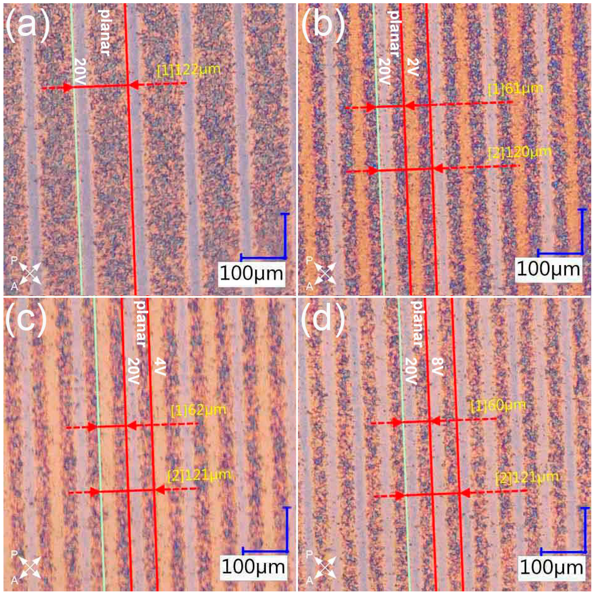
| Grating | Period Measured under a Microscope [µm] | Measured Distance between 0th and 1st Diffraction Order [cm] | Period Calculated Based on Diffraction Pattern [µm] |
|---|---|---|---|
| 20 V | 122.0 (1.2) | 1.463 (0.014) | 121.9 (2.8) |
| 2 V/20 V | 61.0 (1.2) | 2.938 (0.014) | 60.7 (1.4) |
| 120.0 (1.2) | 1.463 (0.014) | 121.8 (2.8) | |
| 4 V/20 V | 62.0 (1.2) | 2.938 (0.014) | 60.7 (1.4) |
| 121.0 (1.2) | 1.463 (0.014) | 121.8 (2.8) | |
| 8 V/20 V | 60.0 (1.2) | 2.950 (0.014) | 60.4 (1.4) |
| 121.0 (1.2) | 1.463 (0.014) | 121.8 (2.8) |
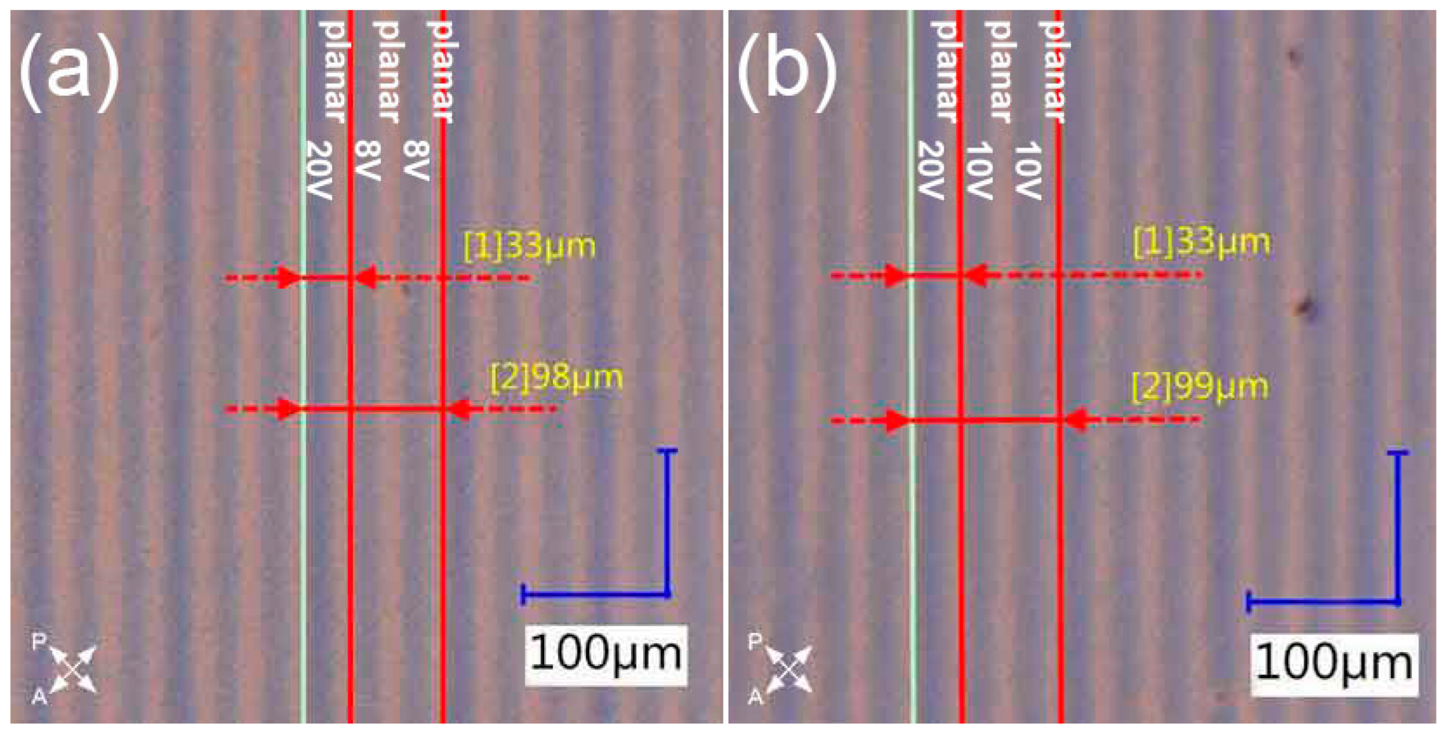
| Grating | Period Measured under a Microscope [µm] | Measured Distance between 0th and 1st Diffraction Order [cm] | Period Calculated Based on Diffraction Pattern [µm] |
|---|---|---|---|
| 8 V/20 V | 33.0 (1.2) | 5.363 (0.014) | 33.23 (0.75) |
| 98.0 (1.2) | 1.800 (0.014) | 99.0 (2.3) | |
| 10 V/20 V | 33.0 (1.2) | 5.400 (0.014) | 33.00 (0.75) |
| 99.0 (1.2) | 1.800 (0.014) | 99.0 (2.3) |
Disclaimer/Publisher’s Note: The statements, opinions and data contained in all publications are solely those of the individual author(s) and contributor(s) and not of MDPI and/or the editor(s). MDPI and/or the editor(s) disclaim responsibility for any injury to people or property resulting from any ideas, methods, instructions or products referred to in the content. |
© 2023 by the authors. Licensee MDPI, Basel, Switzerland. This article is an open access article distributed under the terms and conditions of the Creative Commons Attribution (CC BY) license (https://creativecommons.org/licenses/by/4.0/).
Share and Cite
Kajkowska, M.; Chychłowski, M.S.; Ertman, S.; Lesiak, P. Dual-Period Polarization-Dependent Diffraction Gratings Based on a Polymer-Stabilized Liquid Crystal. Materials 2023, 16, 7313. https://doi.org/10.3390/ma16237313
Kajkowska M, Chychłowski MS, Ertman S, Lesiak P. Dual-Period Polarization-Dependent Diffraction Gratings Based on a Polymer-Stabilized Liquid Crystal. Materials. 2023; 16(23):7313. https://doi.org/10.3390/ma16237313
Chicago/Turabian StyleKajkowska, Marta, Miłosz Sławomir Chychłowski, Sławomir Ertman, and Piotr Lesiak. 2023. "Dual-Period Polarization-Dependent Diffraction Gratings Based on a Polymer-Stabilized Liquid Crystal" Materials 16, no. 23: 7313. https://doi.org/10.3390/ma16237313
APA StyleKajkowska, M., Chychłowski, M. S., Ertman, S., & Lesiak, P. (2023). Dual-Period Polarization-Dependent Diffraction Gratings Based on a Polymer-Stabilized Liquid Crystal. Materials, 16(23), 7313. https://doi.org/10.3390/ma16237313