
Study on the Internal Stress and Thermal Anisotropy in Magnesium Alloys Using a Thermal Elastic Viscoplastic Self-Consistent Model


Abstract
:1. Introduction
2. Methodology
3. Modeling
4. Results
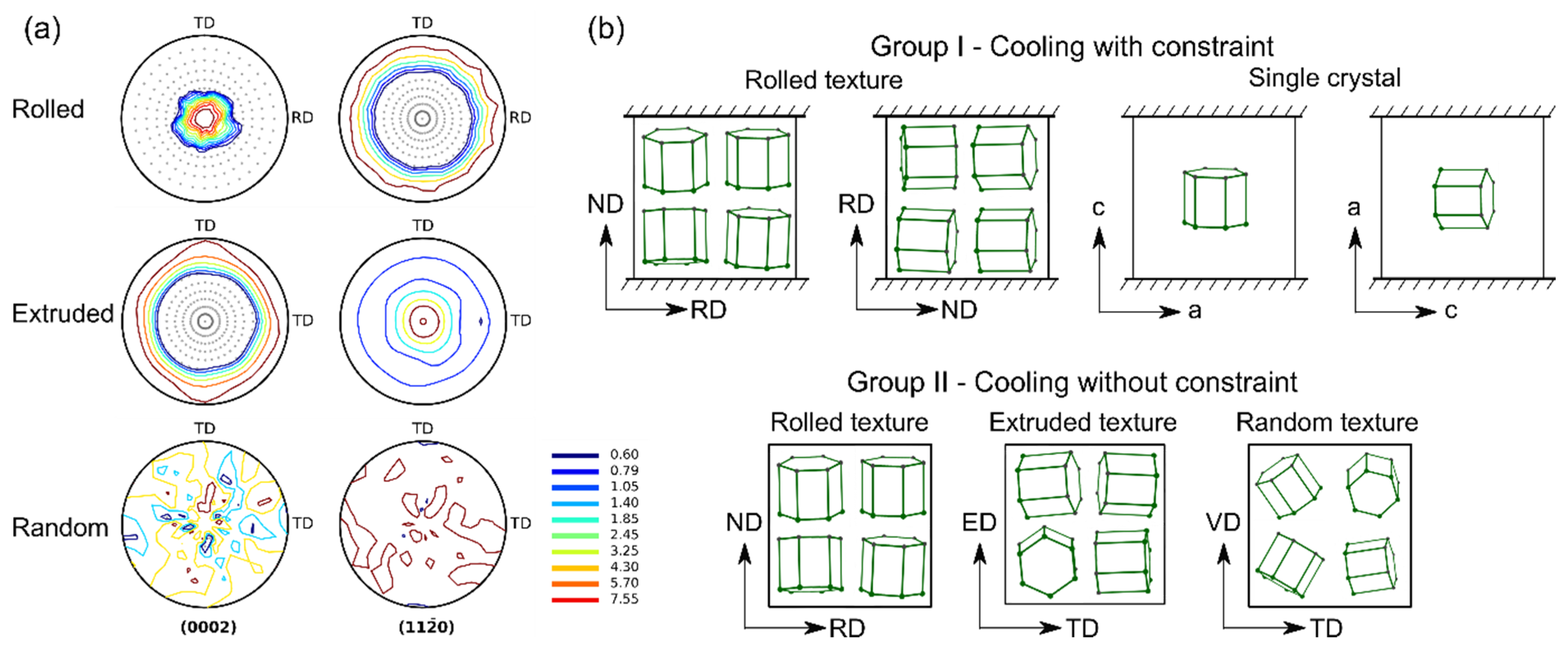
4.1. Group I
- (1)
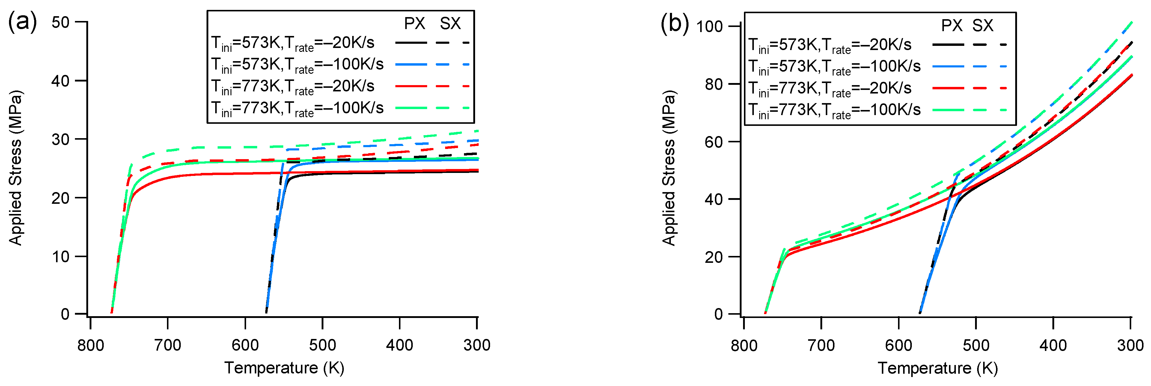
- Stress response
- (2)
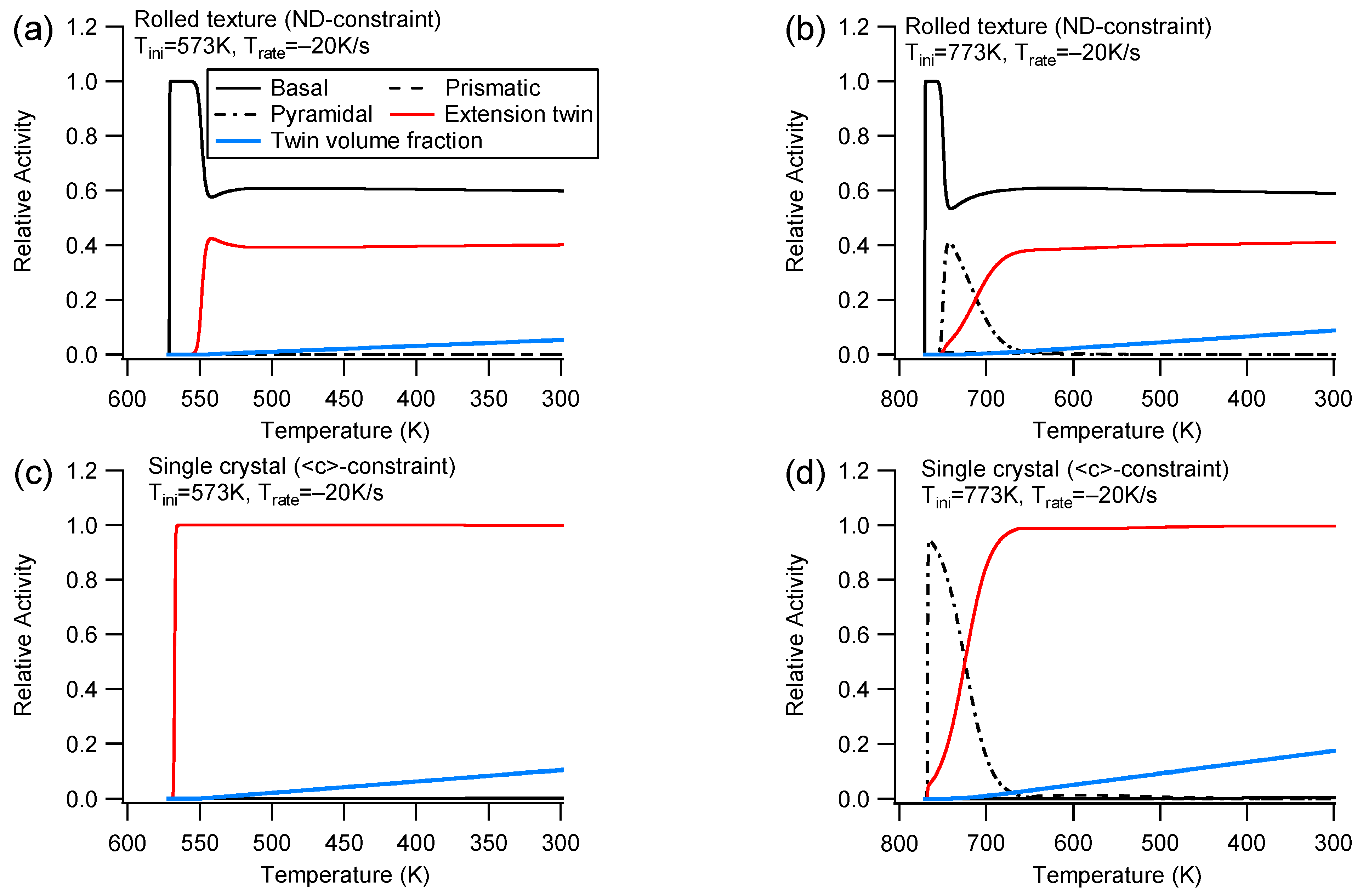
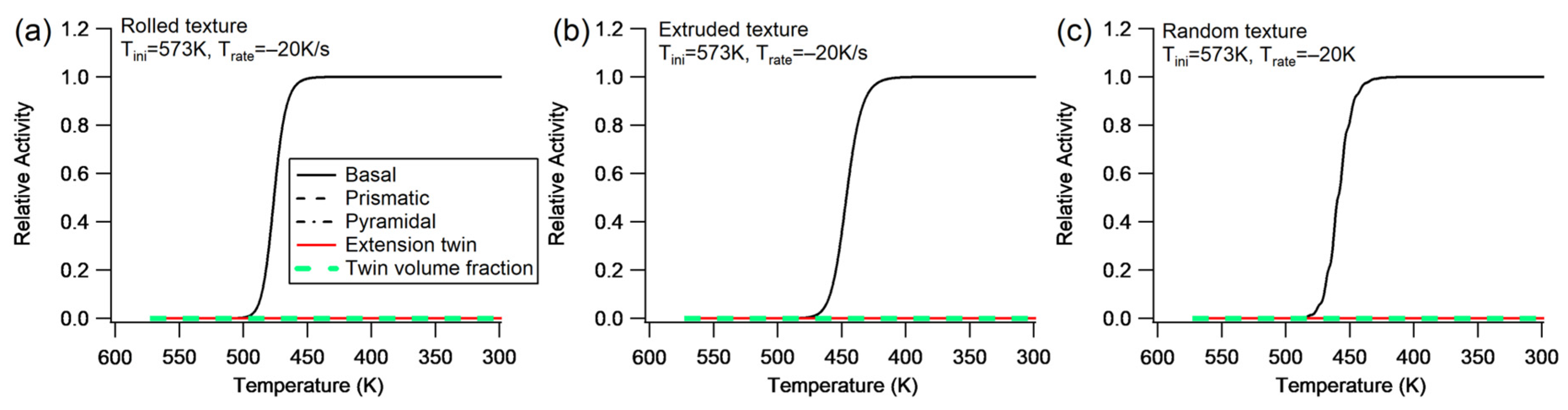
- Slip and twinning activities
- (3)
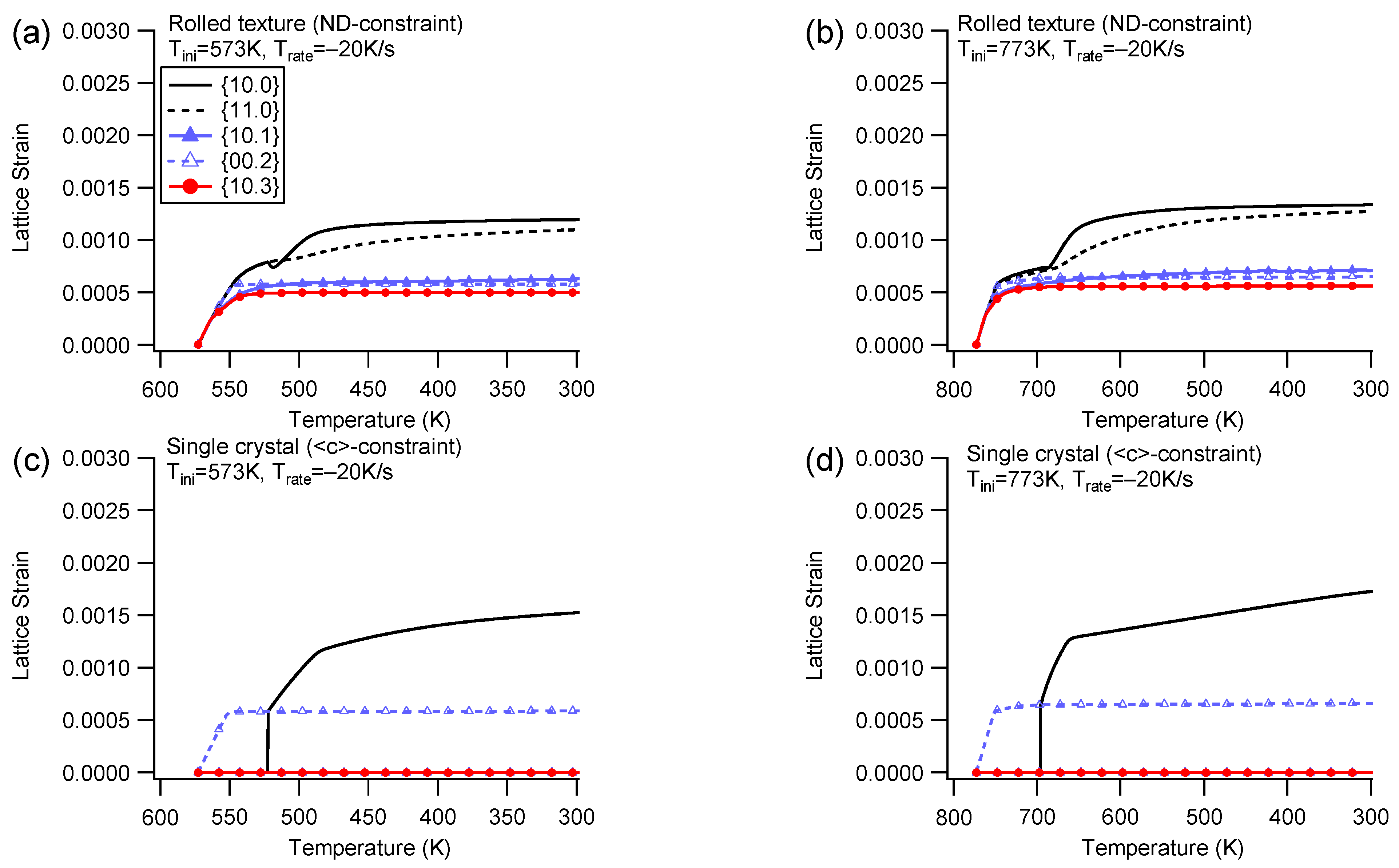
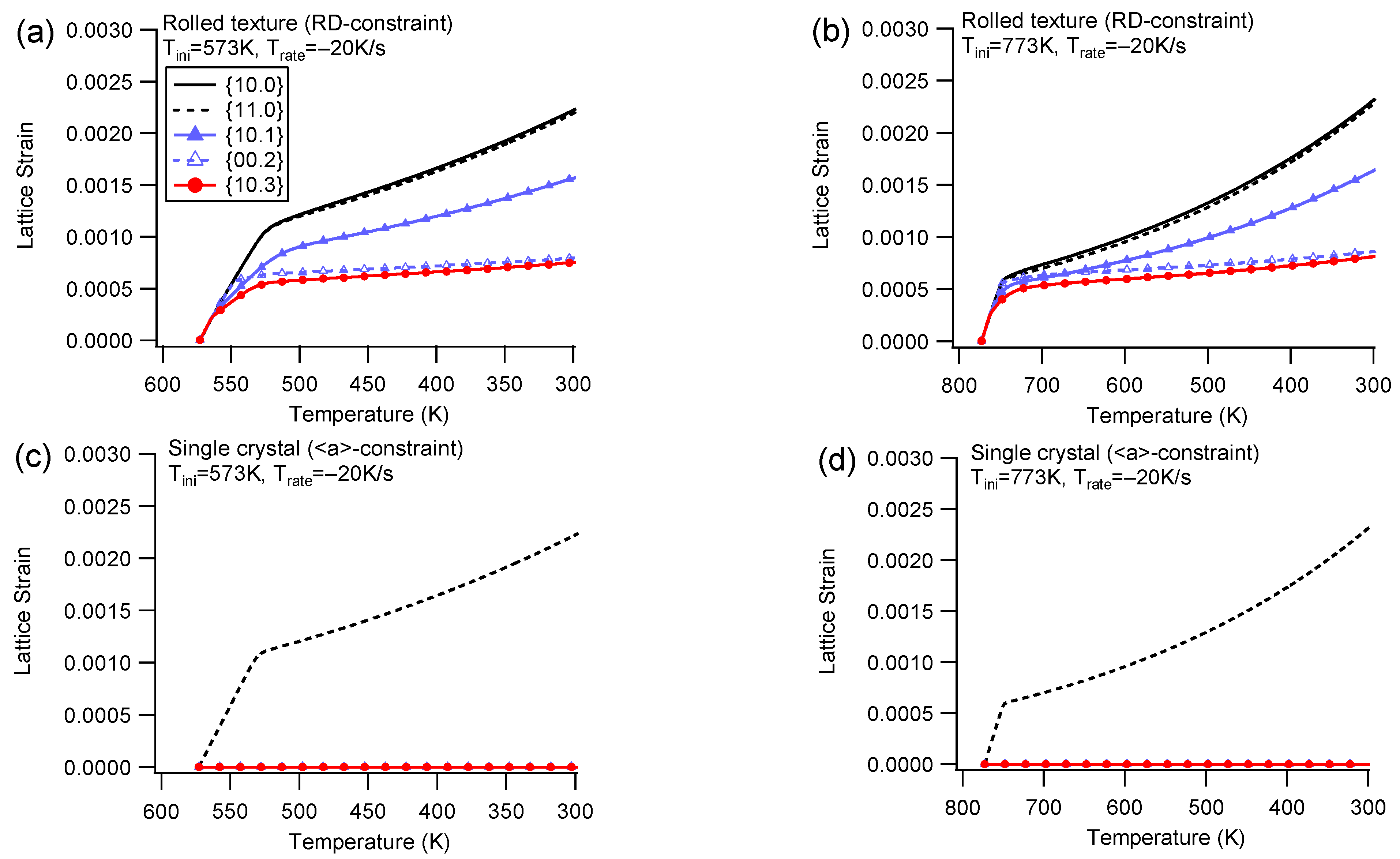
- Elastic lattice strain
4.2. Group II
- (1)
- Slip and twinning activities
- (2)
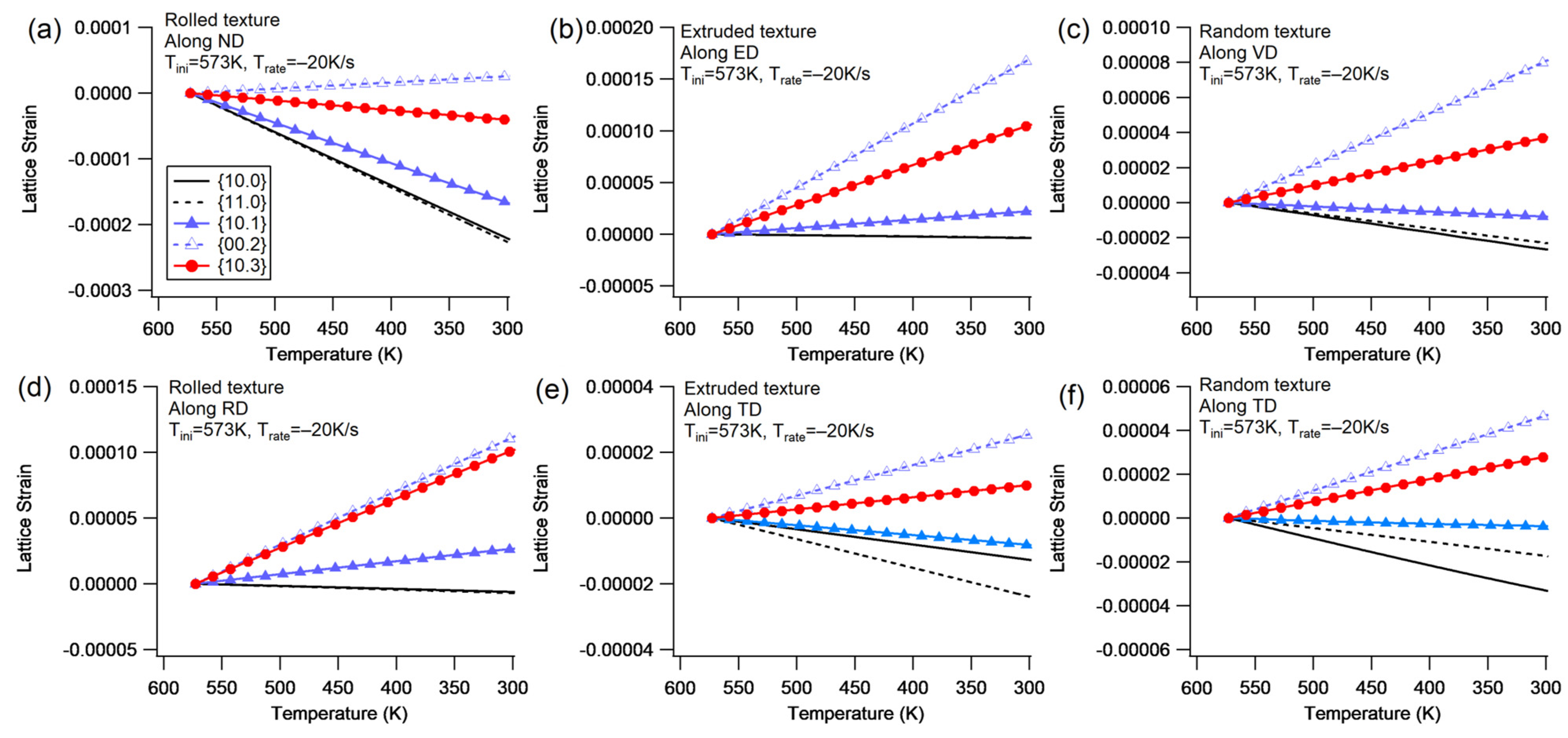
- Elastic lattice strain
5. Discussion
5.1. Influence of Thermal Anisotropy for the Single Crystal
5.2. The Role of Intrinsic Thermal Stress in Macroscale Cooling
6. Conclusions
- (1)
- The elastic lattice strain is significantly higher under cooling with constraint compared to that under cooling without constraint. The deformation mechanism observed under cooling with constraint resembles tension along the direction of constraint at room temperature. Polycrystals offer more deformation mechanisms to accommodate the thermal anisotropy, leading to a lower applied stress within the constrained boundary, in contrast to the single crystal.
- (2)
- Among the observed textures, the maximum amplitude of residual lattice strain follows this order, from high to low: rolled > extruded > random. The overall polycrystals exhibit lower internal stress due to reduced thermal anisotropy. In the rolled texture, the {10.0} and {11.0} planes experience the highest magnitude of compressive lattice strain, while the extruded texture demonstrates the highest magnitude of tensile lattice strain on the {00.2} plane.
- (3)
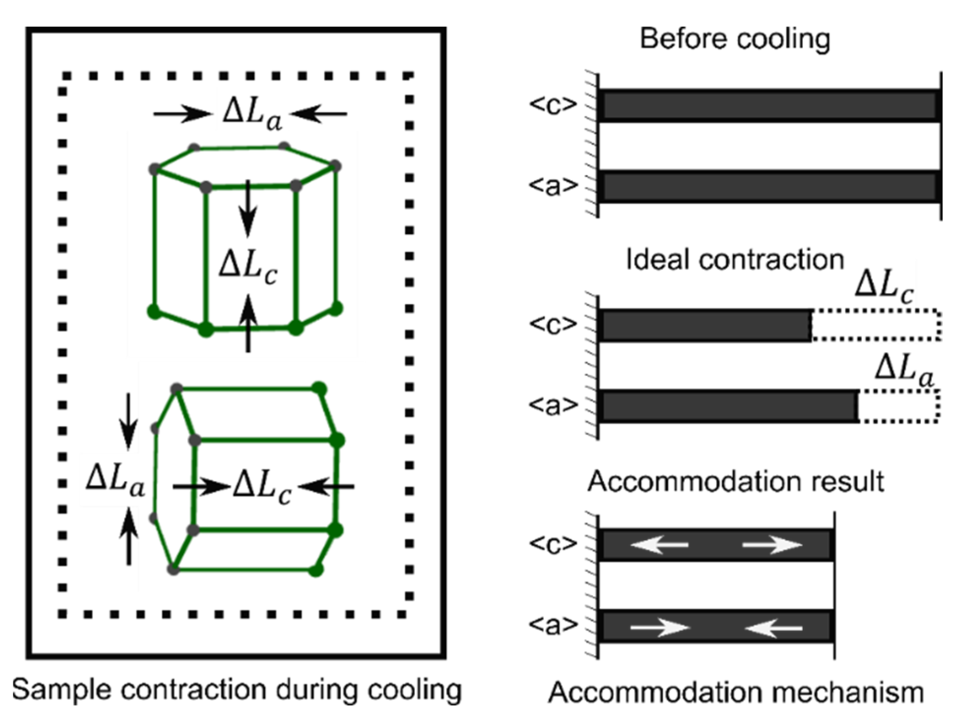
- The strain accommodation mechanism during cooling without constraint can be captured by the thermal EVPSC model, in which the intrinsic thermal strain is solely derived from the interactions between grains. As the cooling process progresses, a single crystal within aggregates contracts more prominently along the <c> direction compared to the <a> direction. Consequently, the {00.2} plane undergoes tensile lattice strain, while the {10.0} and {11.0} planes experience compressive lattice strain.
- (4)
- A speculation is proposed that the macroscopic thermal stress is the sum of the intrinsic thermal stress and the additional stress induced by a macroscale strain mismatch. Based on this hypothesis and the strain accommodation mechanism during cooling, a deeper understanding of the anisotropic residual stress can be promoted to macroscale cooling.
Author Contributions
Funding
Institutional Review Board Statement
Informed Consent Statement
Data Availability Statement
Acknowledgments
Conflicts of Interest
References
- Tresa, M. Pollock Weight Loss with Magnesium Alloys. Science 2010, 328, 985–986. [Google Scholar]
- Ali, Y.; Qiu, D.; Jiang, B.; Pan, F.; Zhang, M.X. Current research progress in grain refinement of cast magnesium alloys: A review article. J. Alloys Compd. 2015, 619, 639–651. [Google Scholar] [CrossRef]
- Yang, Y.; Xiong, X.; Chen, J.; Peng, X.; Chen, D.; Pan, F. Research advances in magnesium and magnesium alloys worldwide in 2020. J. Magnes. Alloys 2021, 9, 705–747. [Google Scholar] [CrossRef]
- Song, J.; She, J.; Chen, D.; Pan, F. Latest research advances on magnesium and magnesium alloys worldwide. J. Magnes. Alloys 2020, 8, 1–41. [Google Scholar] [CrossRef]
- Agnew, S.R.; Duygulu, Ö. Plastic anisotropy and the role of non-basal slip in magnesium alloy AZ31B. Int. J. Plast. 2005, 21, 1161–1193. [Google Scholar] [CrossRef]
- Sarker, D.; Chen, D.L. Dependence of compressive deformation on pre-strain and loading direction in an extruded magnesium alloy: Texture, twinning and de-twinning. Mater. Sci. Eng. A 2014, 596, 134–144. [Google Scholar] [CrossRef]
- Park, S.H.; Hong, S.G.; Lee, C.S. In-plane anisotropic deformation behavior of rolled Mg-3Al-1Zn alloy by initial {10–12} twins. Mater. Sci. Eng. A 2013, 570, 149–163. [Google Scholar] [CrossRef]
- Wu, W.; Chuang, C.P.; Qiao, D.; Ren, Y.; An, K. Investigation of deformation twinning under complex stress states in a rolled magnesium alloy. J. Alloys Compd. 2016, 683, 619–633. [Google Scholar] [CrossRef]
- Turner, P.A.; Tomé, C.N. A study of residual stresses in Zircaloy-2 with rod texture. Acta Metall. Mater. 1994, 42, 4143–4153. [Google Scholar] [CrossRef]
- Tomé, C.N.; Christodoulou, N.; Turner, P.A.; Miller, M.A.; Woo, C.H.; Root, J.; Holden, T.M. Role of internal stresses in the transient of irradiation growth of Zircaloy-2. J. Nucl. Mater. 1996, 227, 237–250. [Google Scholar] [CrossRef]
- Salvati, E.; Sui, T.; Korsunsky, A.M. Uncertainty quantification of residual stress evaluation by the FIB-DIC ring-core method due to elastic anisotropy effects. Int. J. Solids Struct. 2016, 87, 61–69. [Google Scholar] [CrossRef]
- Agnew, S.R.; Tomé, C.N.; Brown, D.W.; Holden, T.M.; Vogel, S.C. Study of slip mechanisms in a magnesium alloy by neutron diffraction and modeling. Scr. Mater. 2003, 48, 1003–1008. [Google Scholar] [CrossRef]
- Agnew, S.R.; Brown, D.W.; Tomé, C.N. Validating a polycrystal model for the elastoplastic response of magnesium alloy AZ31 using in situ neutron diffraction. Acta Mater. 2006, 54, 4841–4852. [Google Scholar] [CrossRef]
- Clausen, B.; Tomé, C.N.; Brown, D.W.; Agnew, S.R. Reorientation and stress relaxation due to twinning: Modeling and experimental characterization for Mg. Acta Mater. 2008, 56, 2456–2468. [Google Scholar] [CrossRef]
- Wang, H.; Wu, P.D.; Wang, J. Modeling inelastic behavior of magnesium alloys during cyclic loading-unloading. Int. J. Plast. 2013, 47, 49–64. [Google Scholar] [CrossRef]
- Wang, H.; Lee, S.Y.; Huang, E.W.; Jain, J.; Li, D.; Peng, Y.; Choi, H.S.; Wu, P. Crystal plasticity modeling and neutron diffraction measurements of a magnesium AZ31B plate: Effects of plastic anisotropy and surrounding grains. J. Mech. Phys. Solids 2020, 135, 103795. [Google Scholar] [CrossRef]
- Zhao, L.; Guan, B.; Xin, Y.; Huang, X.; Liu, C.; Wu, P.; Liu, Q. A quantitative study on mechanical behavior of Mg alloys with bimodal texture components. Acta Mater. 2021, 214, 117013. [Google Scholar] [CrossRef]
- Lee, S.Y.; Gharghouri, M.A. Pseudoelastic behavior of magnesium alloy during twinning-dominated cyclic deformation. Mater. Sci. Eng. A 2013, 572, 98–102. [Google Scholar] [CrossRef]
- Wu, L.; Agnew, S.R.; Brown, D.W.; Stoica, G.M.; Clausen, B.; Jain, A. Internal stress relaxation and load redistribution during the twinning—Detwinning-dominated cyclic deformation of a wrought magnesium alloy, ZK60A. Acta Mater. 2008, 56, 3699–3707. [Google Scholar] [CrossRef]
- Tang, W.; Lee, J.Y.; Wang, H.; Steglich, D.; Li, D.; Peng, Y.; Wu, P. Unloading behaviors of the rare-earth magnesium alloy ZE10 sheet. J. Magnes. Alloys 2020, 9, 927–936. [Google Scholar] [CrossRef]
- Wang, H.; Lee, S.Y.; Wang, H.; Woo, W.; Huang, E.W.; Jain, J.; An, K. On plastic anisotropy and deformation history-driven anelasticity of an extruded magnesium alloy. Scr. Mater. 2020, 176, 36–41. [Google Scholar] [CrossRef]
- Wu, W.; Qiao, H.; An, K.; Guo, X.; Wu, P.; Liaw, P.K. Investigation of deformation dynamics in a wrought magnesium alloy. Int. J. Plast. 2014, 62, 105–120. [Google Scholar] [CrossRef]
- Wang, H.; Clausen, B.; Capolungo, L.; Beyerlein, I.J.; Wang, J.; Tomé, C.N. Stress and strain relaxation in magnesium AZ31 rolled plate: In-situ neutron measurement and elastic viscoplastic polycrystal modeling. Int. J. Plast. 2016, 79, 275–292. [Google Scholar] [CrossRef]
- Jain, A.; Agnew, S.R. Modeling the temperature dependent effect of twinning on the behavior of magnesium alloy AZ31B sheet. Mater. Sci. Eng. A 2007, 462, 29–36. [Google Scholar] [CrossRef]
- Chapuis, A.; Driver, J.H. Temperature dependency of slip and twinning in plane strain compressed magnesium single crystals. Acta Mater. 2011, 59, 1986–1994. [Google Scholar] [CrossRef]
- Hutchinson, W.B.; Barnett, M.R. Effective values of critical resolved shear stress for slip in polycrystalline magnesium and other hcp metals. Scr. Mater. 2010, 63, 737–740. [Google Scholar] [CrossRef]
- Kröner, E. On the plastic deformation of polycrystals. Acta Metall. 1961, 9, 155–161. [Google Scholar] [CrossRef]
- Hill, R. A self-consistent mechanics of composite materials. J. Mech. Phys. Solids 1965, 13, 213–222. [Google Scholar] [CrossRef]
- Zienkiewicz, O.C.; Taylor, R.L. Finite Element Method for Solid and Structural Mechanics, 6th ed.; Elsevier: Amsterdam, The Netherlands, 2005; pp. 6–8. [Google Scholar]
- Robinson, J.S.; Tanner, D.A.; Truman, C.E.; Paradowska, A.M.; Wimpory, R.C. The influence of quench sensitivity on residual stresses in the aluminium alloys 7010 and 7075. Mater. Charact. 2012, 65, 73–85. [Google Scholar] [CrossRef]
- Koç, M.; Culp, J.; Altan, T. Prediction of residual stresses in quenched aluminum blocks and their reduction through cold working processes. J. Mater. Process. Technol. 2006, 174, 342–354. [Google Scholar] [CrossRef]
- Bouafia, F.; Serier, B.; Bouiadjra, B.A.B. Finite element analysis of the thermal residual stresses of SiC particle reinforced aluminum composite. Comput. Mater. Sci. 2012, 54, 195–203. [Google Scholar] [CrossRef]
- Liao, H.; Ma, M.; Li, X.; Zhang, K.; Li, Y.; Shi, G. Residual stresses in spray quenched EW75 magnesium alloy. Mater. Sci. Forum 2013, 747–748, 172–177. [Google Scholar] [CrossRef]
- Wang, C.; Luo, T.; Zhou, J.; Yang, Y. Effects of solution and quenching treatment on the residual stress in extruded ZK60 magnesium alloy. Mater. Sci. Eng. A 2018, 722, 14–19. [Google Scholar] [CrossRef]
- Wang, C.; Luo, T.; Liu, Y.; Huang, Q.; Yang, Y. Residual stress and precipitation of Mg-5Zn-3.5Sn-1Mn-0.5Ea-0.5Cu alloy with different quenching rates. J. Magnes. Alloys 2021, 9, 604–612. [Google Scholar] [CrossRef]
- Lebensohn, R.A.; Tomé, C.N. A self-consistent anisotropic approach for the simulation of plastic deformation and texture development of polycrystals: Application to zirconium alloys. Acta Metall. Mater. 1993, 41, 2611–2624. [Google Scholar] [CrossRef]
- Lebensohn, R.A.; Tomé, C.N.; Maudlin, P.J. A selfconsistent formulation for the prediction of the anisotropic behavior of viscoplastic polycrystals with voids. J. Mech. Phys. Solids 2004, 52, 249–278. [Google Scholar] [CrossRef]
- Segurado, J.; Lebensohn, R.A.; Llorca, J. Computational Homogenization of Polycrystals. In Advances in Applied Mechanics; Academic Press: Cambridge, MA, USA, 2018; Volume 51, pp. 1–114. [Google Scholar]
- Beyerlein, I.J.; Knezevic, M. Review of microstructure and micromechanism-based constitutive modeling of polycrystals with a low-symmetry crystal structure. J. Mater. Res. 2018, 33, 3711–3738. [Google Scholar] [CrossRef]
- Wang, H.; Wu, P.D.; Tomé, C.N.; Wang, J. A constitutive model of twinning and detwinning for hexagonal close packed polycrystals. Mater. Sci. Eng. A 2012, 555, 93–98. [Google Scholar] [CrossRef]
- Wang, H.; Wu, P.D.; Wang, J.; Tomé, C.N. A crystal plasticity model for hexagonal close packed (HCP) crystals including twinning and de-twinning mechanisms. Int. J. Plast. 2013, 49, 36–52. [Google Scholar] [CrossRef]
- Lebensohn, R.A.; Tomé, C.N. A self-consistent viscoplastic model: Prediction of rolling textures of anisotropic polycrystals. Mater. Sci. Eng. A 1994, 175, 71–82. [Google Scholar] [CrossRef]
- Varshni, Y.P. Temperature dependence of the elastic constants. Phys. Rev. B 1970, 2, 3952–3958. [Google Scholar] [CrossRef]
- Barnett, M.R. A Taylor model based description of the proof stress of magnesium AZ31 during hot working. Metall. Mater. Trans. A Phys. Metall. Mater. Sci. 2003, 34A, 1799–1806. [Google Scholar] [CrossRef]
- Zhou, G.; Jain, M.K.; Wu, P.; Shao, Y.; Li, D.; Peng, Y. Experiment and crystal plasticity analysis on plastic deformation of AZ31B Mg alloy sheet under intermediate temperatures: How deformation mechanisms evolve. Int. J. Plast. 2016, 79, 19–47. [Google Scholar] [CrossRef]
- Beyerlein, I.J.; Tomé, C.N. A dislocation-based constitutive law for pure Zr including temperature effects. Int. J. Plast. 2008, 24, 867–895. [Google Scholar] [CrossRef]
- Olsson, P.A.T. First principles investigation of the finite temperature dependence of the elastic constants of zirconium, magnesium and gold. Comput. Mater. Sci. 2015, 99, 361–372. [Google Scholar] [CrossRef]
- Wang, H.; Wu, P.; Kurukuri, S.; Worswick, M.J.; Peng, Y.; Tang, D.; Li, D. Strain rate sensitivities of deformation mechanisms in magnesium alloys. Int. J. Plast. 2018, 107, 207–222. [Google Scholar] [CrossRef]
- Wang, H.; Raeisinia, B.; Wu, P.D.; Agnew, S.R.; Tomé, C.N. Evaluation of self-consistent polycrystal plasticity models for magnesium alloy AZ31B sheet. Int. J. Solids Struct. 2010, 47, 2905–2917. [Google Scholar] [CrossRef]
- Wang, H.; Wu, P.D.; Tomé, C.N.; Huang, Y. A finite strain elastic-viscoplastic self-consistent model for polycrystalline materials. J. Mech. Phys. Solids 2010, 58, 594–612. [Google Scholar] [CrossRef]
- Bridgman, P.W. Physical Properties of Single Crystal Magnesium. Proc. Am. Acad. Arts Sci. 1932, 67, 29–41. [Google Scholar] [CrossRef]
- Pathak, P.D.; Desai, R.J. Thermal expansion of magnesium and temperature variation of negative second moment of its frequency spectrum. Phys. Status Solidi 1981, 66, K179–K182. [Google Scholar] [CrossRef]
- Zhu, X.; Wang, Y.; Carneiro, L.; Wang, H.; Jiang, Y. Evaluation of elastic-viscoplastic self-consistent models for a rolled AZ31B magnesium alloy under monotonic loading along five different material orientations and free-end torsion. J. Magnes. Alloys 2023, 11, 1264–1275. [Google Scholar] [CrossRef]
- Xu, F.; Holt, R.A.; Daymond, M.R. Modeling lattice strain evolution during uniaxial deformation of textured Zircaloy-2. Acta Mater. 2008, 56, 3672–3687. [Google Scholar] [CrossRef]
- Qiao, H.; Wu, P.D.; Wang, H.; Gharghouri, M.A.; Daymond, M.R. Evaluation of elastic-viscoplastic self-consistent polycrystal plasticity models for zirconium alloys. Int. J. Solids Struct. 2015, 71, 308–322. [Google Scholar] [CrossRef]
- Xu, F. Lattice Strain and Texture Evolution During Room-Temperature Deformation in Zircaloy-2. Ph.D. Thesis, Queen’s University, Kingston, ON, Canada, 2007. [Google Scholar]
- Xu, C.; Wang, J.; Liu, S.; Wang, Z.; Ru, K.; Sun, S.; Sun, Y. Effect of quenching temperature on microstructure and mechanical properties of Mg-35 wt%Sc alloy. J. Alloys Compd. 2023, 943, 169165. [Google Scholar] [CrossRef]
- Woo, W. Severe Plastic Deformation Using Friction Stir Processing, and the Characterization of Microstructure and Mechanical Behavior Using Neutron Diffraction. Ph.D Thesis, University of Tennessee, Knoxville, TN, USA, 2006. [Google Scholar]
- Woo, W.; Choo, H.; Prime, M.B.; Feng, Z.; Clausen, B. Microstructure, texture and residual stress in a friction-stir-processed AZ31B magnesium alloy. Acta Mater. 2008, 56, 1701–1711. [Google Scholar] [CrossRef]
- Park, S.H.C.; Sato, Y.S.; Kokawa, H. Basal plane texture and flow pattern in friction stir weld of a magnesium alloy. Metall. Mater. Trans. A Phys. Metall. Mater. Sci. 2003, 34A, 987–994. [Google Scholar] [CrossRef]
- Xin, R.; Sun, L.; Liu, D.; Zhou, Z.; Liu, Q. Effect of subsequent tension and annealing on microstructure evolution and strength enhancement of friction stir welded Mg alloys. Mater. Sci. Eng. A 2014, 602, 1–10. [Google Scholar] [CrossRef]
- Mironov, S.; Onuma, T.; Sato, Y.S.; Kokawa, H. Microstructure evolution during friction-stir welding of AZ31 magnesium alloy. Acta Mater. 2015, 100, 301–312. [Google Scholar] [CrossRef]
- Mironov, S.; Onuma, T.; Sato, Y.S.; Yoneyama, S.; Kokawa, H. Microstructural changes during tension of friction-stir welded AZ31 magnesium alloy. Mater. Charact. 2017, 130, 1–8. [Google Scholar] [CrossRef]
- Woo, W.; Choo, H.; Brown, D.W.; Clausen, B.; Feng, Z.L.; Liaw, P.K. Residual Strain Measurements in a Friction-Stir Processed AZ31B Magnesium Alloy Using Neutron Diffraction. Mater. Sci. Forum 2007, 539–543, 3795–3800. [Google Scholar] [CrossRef]


| Mode | (MPa) | Elastic Constant | (MPa) | (MPa) | ||
|---|---|---|---|---|---|---|
| Basal | 5 | - | 6.34 × 10⁴ | 3.577 × 10³ | 192.6 | |
| Prismatic | 158.7 | 306.5 | 2.59 × 10⁴ | 0.661 × 10³ | 339.6 | |
| Pyramidal | 227.9 | 284.8 | 2.17 × 10⁴ | 0.857 × 10³ | 458.4 | |
| Extension twin | 20 | - | 6.64 × 10⁴ | 4.282 × 10³ | 190.2 | |
| 1.84 × 10⁴ | 2.125 × 10³ | 219.9 |
| Constraint Direction | Initial Temp. | Temp. Rate | {10.0} | {11.0} | {10.1} | {00.2} | {10.3} |
|---|---|---|---|---|---|---|---|
| ND | 300 | −20 | 53.9 | 49.6 | 28.4 | 26.2 | 22.6 |
| <c> | 68.7 | 0 | 0 | 26.5 | 0 | ||
| ND | 300 | −100 | 58.1 | 53.3 | 28.3 | 28.3 | 24.3 |
| <c> | 73.4 | 0 | 0 | 28.5 | 0 | ||
| ND | 500 | −20 | 60.2 | 57.5 | 32.0 | 29.3 | 25.4 |
| <c> | 77.9 | 0 | 0 | 29.7 | 0 | ||
| ND | 500 | −100 | 64.8 | 61.9 | 34.4 | 31.5 | 27.0 |
| <c> | 83.6 | 0 | 0 | 32.0 | 0 | ||
| RD | 300 | −20 | 105.8 | 99.2 | 70.8 | 35.8 | 33.9 |
| <a> | 0 | 106.7 | 0 | 0 | 0 | ||
| RD | 300 | −100 | 108.5 | 107.0 | 76.4 | 38.6 | 36.5 |
| <a> | 0 | 108.5 | 0 | 0 | 0 | ||
| RD | 500 | −20 | 104.6 | 103.1 | 74.0 | 38.8 | 36.7 |
| <a> | 0 | 104.6 | 0 | 0 | 0 | ||
| RD | 500 | −100 | 112.8 | 111.2 | 79.7 | 41.8 | 39.4 |
| <a> | 0 | 112.6 | 0 | 0 | 0 |
| Tex. | Ini. Temp./ Temp. Rate | Dir. | {10.0} | {11.0} | {10.1} | {00.2} | {10.3} |
|---|---|---|---|---|---|---|---|
| Rolled | 300/−20 | ND | −10.0 | −10.3 | −7.6 | 1.2 | −1.8 |
| RD | −0.3 | −0.3 | 1.2 | 5.0 | 4.6 | ||
| Rolled | 300/−100 | ND | −10.0 | −10.3 | −7.6 | 1.2 | −1.8 |
| RD | −0.3 | −0.3 | 1.2 | 5.0 | 4.6 | ||
| Rolled | 500/−20 | ND | −17.6 | −18.0 | −12.7 | 1.8 | −2.6 |
| RD | −0.4 | −0.4 | 1.7 | 8.9 | 7.7 | ||
| Rolled | 500/−100 | ND | −17.5 | −17.9 | −12.9 | 1.8 | −2.8 |
| RD | −0.4 | −0.5 | 1.8 | 8.8 | 7.7 | ||
| Extruded | 300/−20 | ED | −0.2 | −0.2 | 1.0 | 7.7 | 4.8 |
| TD | −0.6 | −1.1 | −0.4 | 1.2 | 0.5 | ||
| Extruded | 300/−100 | ED | −0.2 | −0.2 | 1.0 | 7.6 | 4.7 |
| TD | −1.4 | −1.8 | −0.9 | 1.4 | 0.7 | ||
| Extruded | 500/−20 | ED | −0.2 | −0.2 | 1.7 | 13.2 | 7.9 |
| TD | −2.4 | −3.1 | −1.6 | 2.4 | 1.1 | ||
| Extruded | 500/−100 | ED | −0.2 | −0.2 | 1.7 | 13.3 | 8.1 |
| TD | −2.5 | −3.1 | −1.6 | 2.4 | 1.1 | ||
| Random | 300/−20 | VD | −1.2 | −1.0 | −1.0 | 3.6 | 1.7 |
| TD | −1.5 | −0.8 | −0.2 | 2.1 | 1.3 | ||
| Random | 300/−100 | VD | −1.2 | −1.0 | −0.3 | 3.6 | 1.7 |
| TD | −1.5 | −1.4 | 0.0 | 1.2 | 1.1 | ||
| Random | 500/−20 | VD | −2.0 | −1.7 | −0.6 | 6.3 | 2.9 |
| TD | −2.5 | −2.5 | 0.1 | 2.1 | 2.0 | ||
| Random | 500/−100 | VD | −2.1 | −1.8 | −0.6 | 6.3 | 2.9 |
| TD | −2.5 | −2.4 | 0.0 | 2.1 | 2.0 |
Disclaimer/Publisher’s Note: The statements, opinions and data contained in all publications are solely those of the individual author(s) and contributor(s) and not of MDPI and/or the editor(s). MDPI and/or the editor(s) disclaim responsibility for any injury to people or property resulting from any ideas, methods, instructions or products referred to in the content. |
© 2023 by the authors. Licensee MDPI, Basel, Switzerland. This article is an open access article distributed under the terms and conditions of the Creative Commons Attribution (CC BY) license (https://creativecommons.org/licenses/by/4.0/).
Share and Cite
Zhu, X.; Wang, H.; Wu, Y. Study on the Internal Stress and Thermal Anisotropy in Magnesium Alloys Using a Thermal Elastic Viscoplastic Self-Consistent Model. Materials 2023, 16, 7097. https://doi.org/10.3390/ma16227097
Zhu X, Wang H, Wu Y. Study on the Internal Stress and Thermal Anisotropy in Magnesium Alloys Using a Thermal Elastic Viscoplastic Self-Consistent Model. Materials. 2023; 16(22):7097. https://doi.org/10.3390/ma16227097
Chicago/Turabian StyleZhu, Xianyun, Huamiao Wang, and Yunxin Wu. 2023. "Study on the Internal Stress and Thermal Anisotropy in Magnesium Alloys Using a Thermal Elastic Viscoplastic Self-Consistent Model" Materials 16, no. 22: 7097. https://doi.org/10.3390/ma16227097
APA StyleZhu, X., Wang, H., & Wu, Y. (2023). Study on the Internal Stress and Thermal Anisotropy in Magnesium Alloys Using a Thermal Elastic Viscoplastic Self-Consistent Model. Materials, 16(22), 7097. https://doi.org/10.3390/ma16227097