
Effect of the Rolling Process on the Properties of the Mg/Al Bimetallic Bars Obtained by the Explosive Welding Method

 ,
,  ,
,  ,
,  ,
,  ,
,  and
and
Abstract
:1. Introduction
2. Material and Research Methodology
2.1. Rolling of Mg-Al Bimetallic Rods
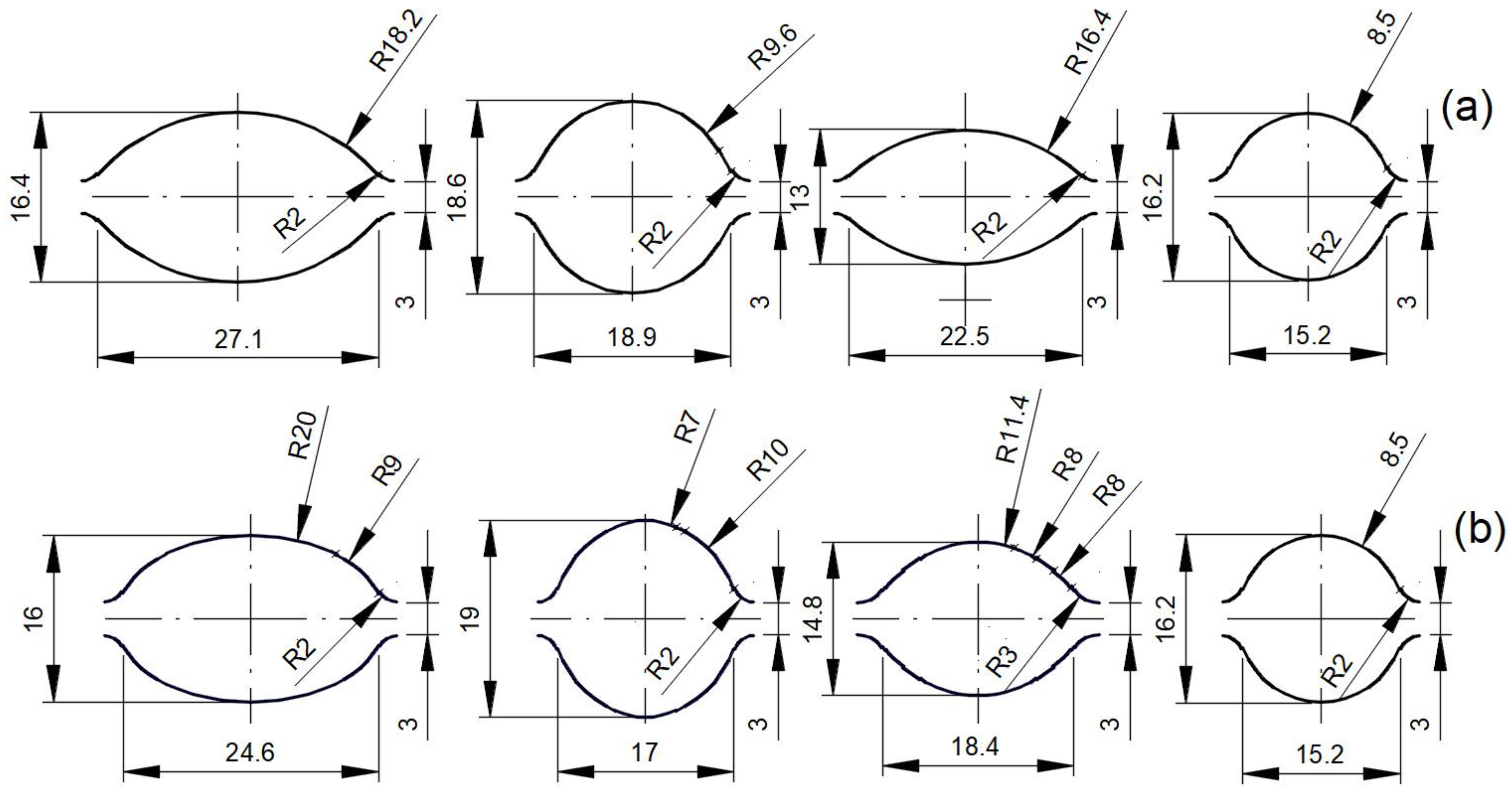
- Variant I: classic pattern of elongating cuts, circle-oval-circle.
- Variant II: modified system of multi-radium elongating circle-oval-circle patterns.
2.2. Microstructural Studies
2.3. Electrochemical Research
2.4. Microhardness Studies
3. Research Results
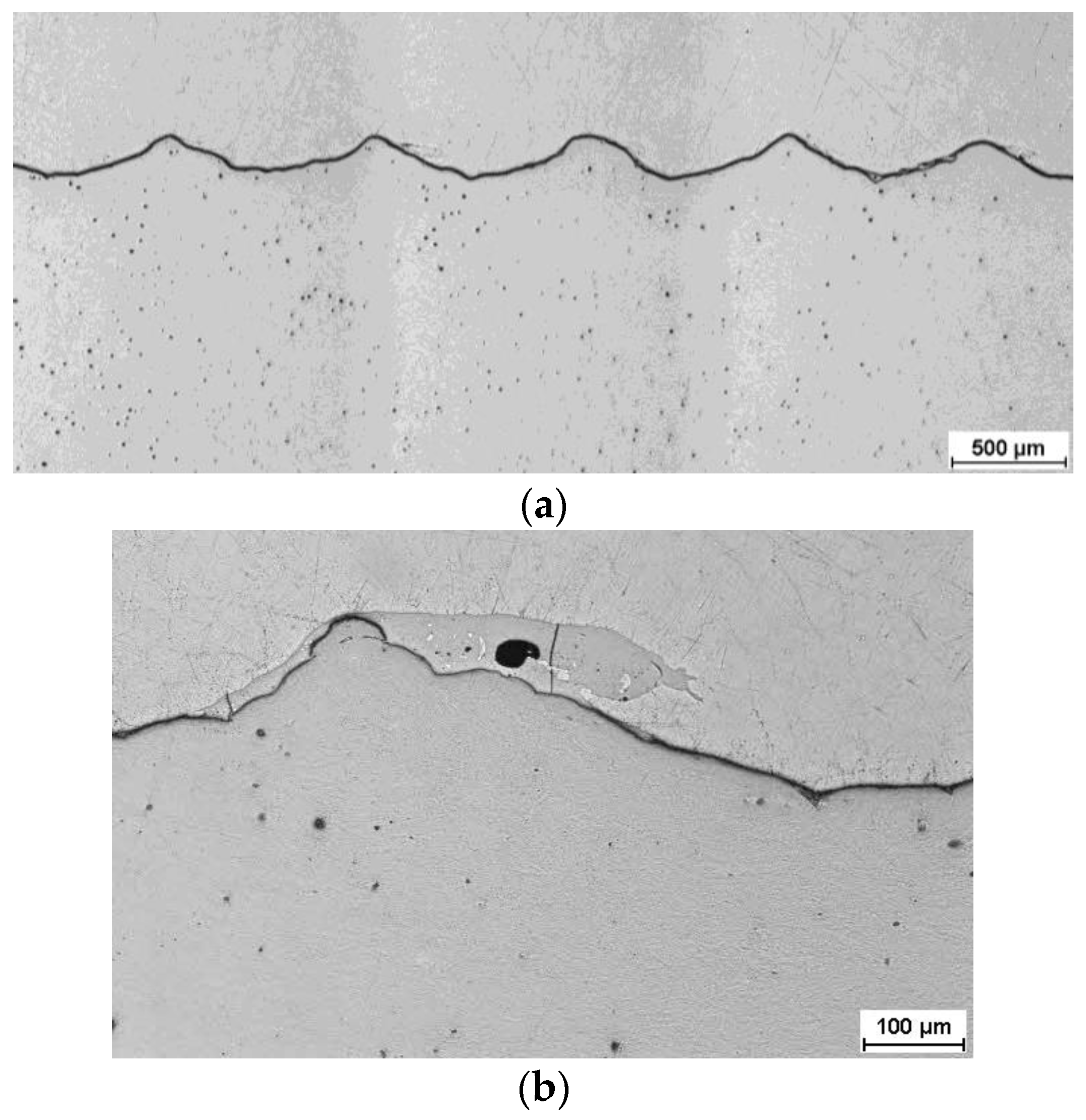
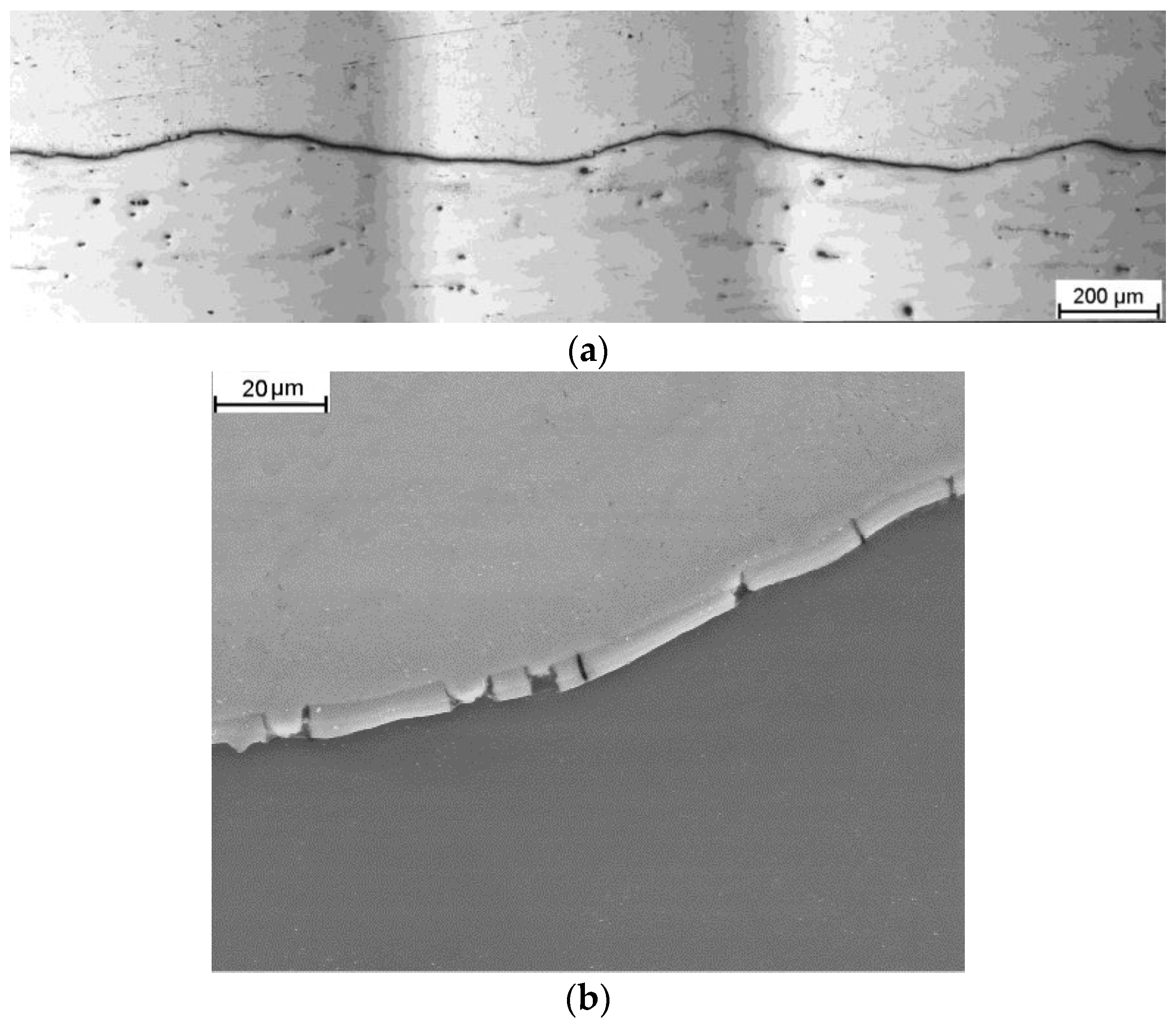
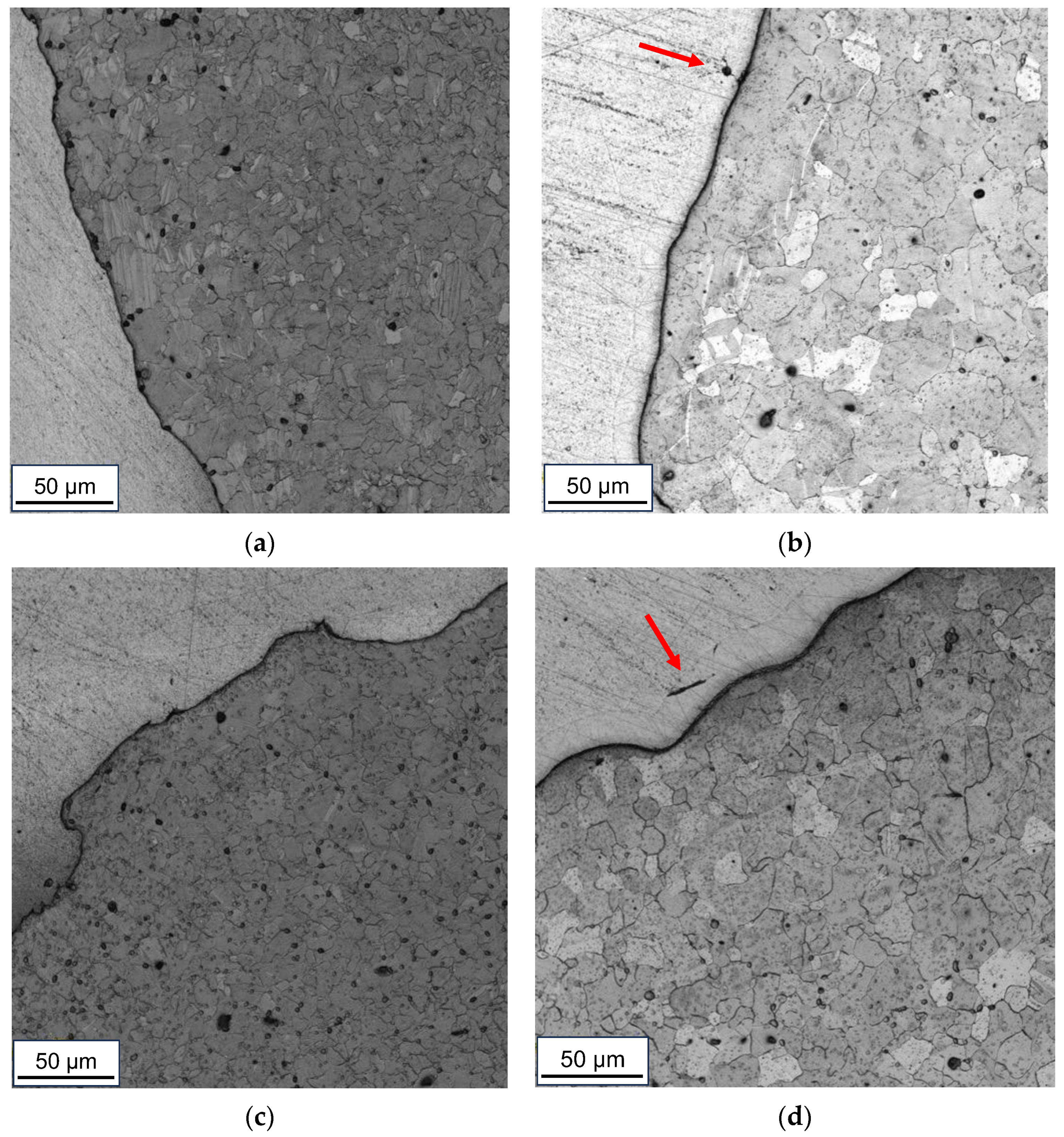
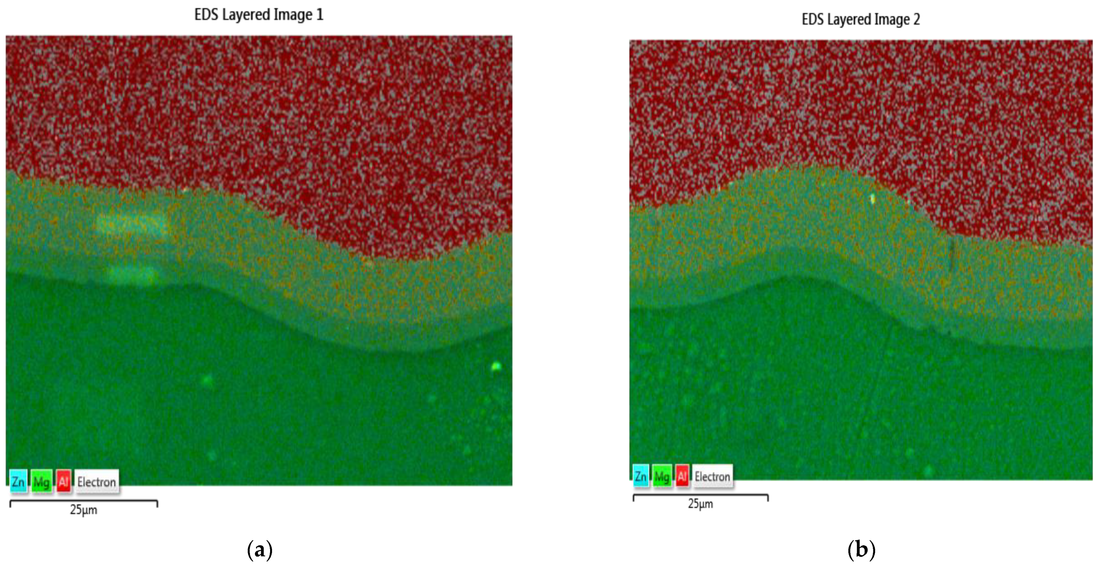
3.1. Microstructural Studies
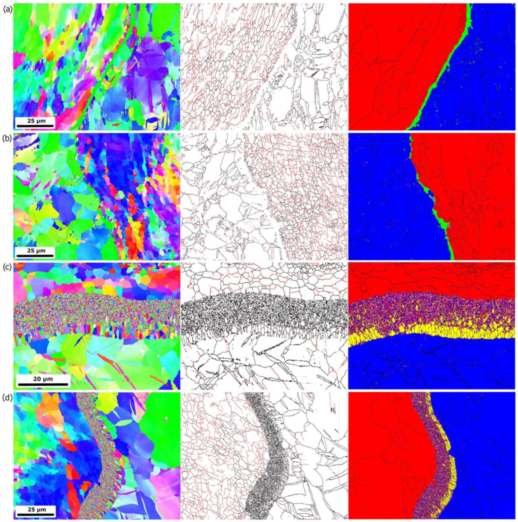
3.2. EBSD Studies
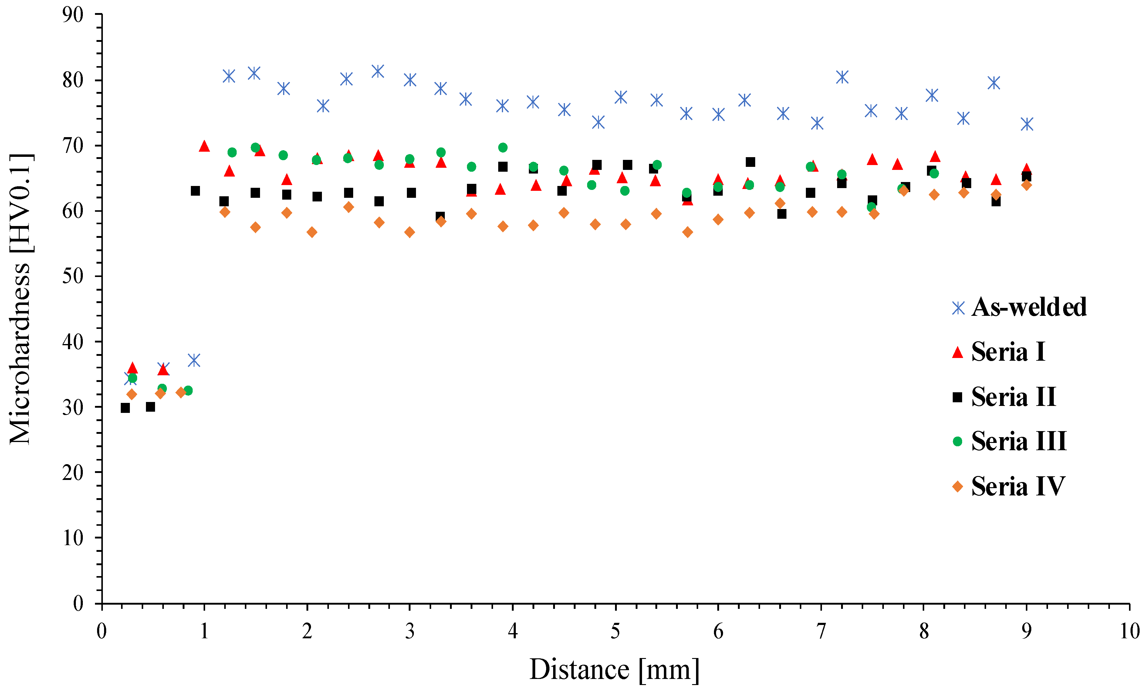
3.3. Microhardness Measurements
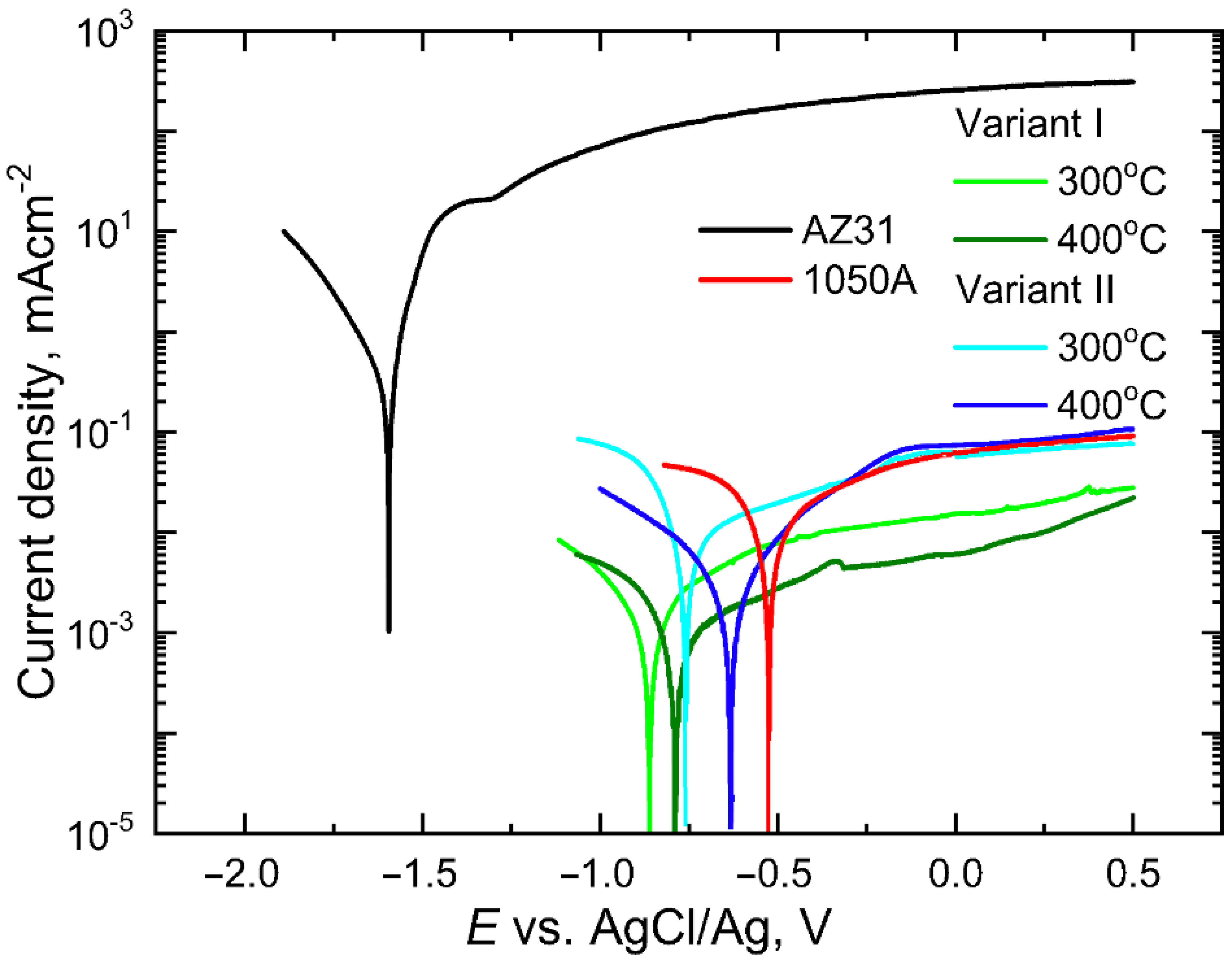
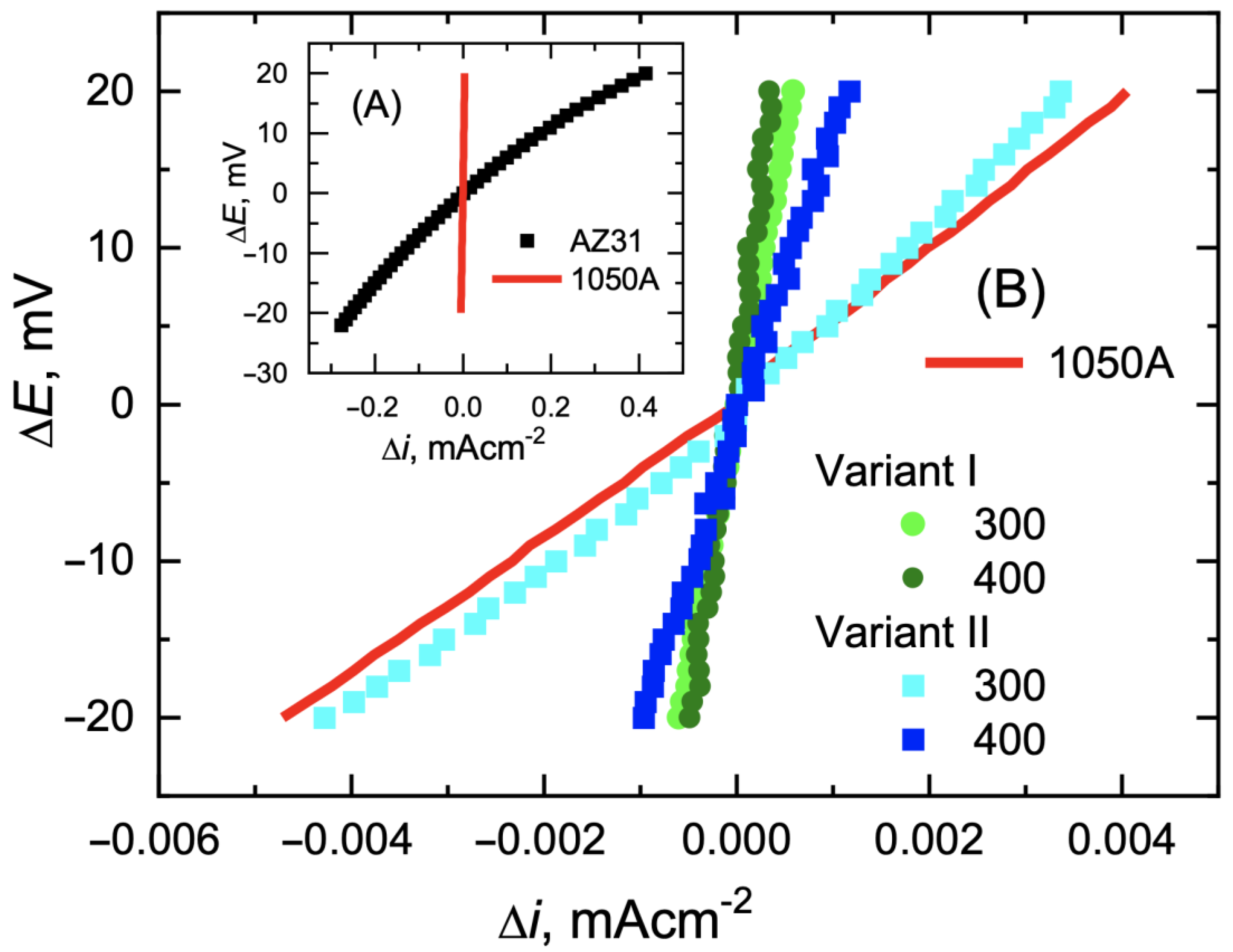
3.4. Electrochemical Research
4. Conclusions
- This study determined the influence of process parameters on the pattern and the possibility of controlling the plastic flow of Mg/Al bimetallic rods during their rolling in elongating grooves.
- Both rolling technologies ensure very good corrosion parameters for the Mg/Al bimetal. After the rolling process, the material shows clearly lower values of both icor and current in the passive range.
- As a result of hot forming, the microhardness of AZ31 has been reduced (compared to the as-welded state) by 15 HV0.1 on average. The reduction in the AA1050 layer is significantly lower and reported only for the rods forming at 400 °C.
- In the transition zone of bimetallic rods rolling at 400 °C, two phases are distinguished—Al3Mg2 and Mg17Al12, localized next to the Mg core, characterized by columnar, coarser grains with lengths within the range of 4–5 µm. Closer to the Al layer, the transition zone consists mainly of the Al3Mg2 phase, characterized by refined, smaller grain sizes. With a 15 share of the cover layer in the cross-section of the bimetallic rod, “variant I—classical rolling” of rolling slows down the dissolution rate slightly more and facilitates the transition of the surface of this material to a passive state.
Author Contributions
Funding
Institutional Review Board Statement
Informed Consent Statement
Data Availability Statement
Conflicts of Interest
References
- Zeng, R.; Zhang, J.; Huang, W.; Dietzel, W.; Kainer, K.U.; Blawert, C.; Wei, K.E. Review of studies on corrosion of magnesium alloys. Trans. Nonferrous Met. Soc. China 2006, 2, 763–771. [Google Scholar] [CrossRef]
- Guo, K.W. A Review of Magnesium/Magnesium Alloys Corrosion. Recent Pat. Corros. Sci. 2011, 1, 72–90. [Google Scholar]
- Predko, P.; Rajnovic, D.; Grilli, M.L.; Postolnyi, B.O.; Zemcenkovs, V.; Rijkuris, G.; Pole, E.; Lisnanskis, M. Promising Methods for Corrosion Protection of Magnesium Alloys in the Case of Mg-Al, Mg-Mn-Ce and Mg-Zn-Zr: A Recent Progress Review. Metals 2021, 11, 1133. [Google Scholar] [CrossRef]
- Gray, J.E.; Luan, B. Protective coatings on magnesium and its alloys-a critical review. J. Alloys Compd. 2002, 336, 88–113. [Google Scholar] [CrossRef]
- Wu, T.; Zhang, K. Corrosion and Protection of Magnesium Alloys: Recent Advances and Future Perspectives. Coatings 2023, 13, 1533. [Google Scholar] [CrossRef]
- Mola, R. The properties of Mg protected by Al- and Al/Zn-enriched layers containing intermetallic phases. J. Mat. Res. 2015, 30, 3682–3691. [Google Scholar] [CrossRef]
- Galun, R.; Weisheit, A.; Mordike, B. Improving the Surface Properties of Magnesium by Laser Alloying. Corros. Rev. 1998, 16, 53–74. [Google Scholar] [CrossRef]
- Ignat, S.; Sallamand, P.; Grevey, D.; Lambertin, M. Magnesium alloys laser (Nd: YAG) cladding and alloying with side injection of aluminium powder. Appl. Surf. Sci. 2004, 225, 124–134. [Google Scholar] [CrossRef]
- Mola, R.; Cieślik, M.; Odo, K. Characteristics of AlSi11-AM60 bimetallic joints produced by diffusion bonding. IOP Conf. Ser. Mater. Sci. Eng. 2018, 461, 012058. [Google Scholar] [CrossRef]
- Liu, W.; Long, L.; Ma, Y.; Wu, l. Microstructure evolution and mechanical properties of Mg/Al diffusion bonded joints. J. Alloys Compd. 2015, 643, 34–39. [Google Scholar] [CrossRef]
- Li, X.; Liang, W.; Zhao, X.; Zhang, Y.; Fu, X.; Liu, F. Bonding of Mg and Al with Mg-Al eutectic alloy and its application in aluminum coating on magnesium. J. Alloys Compd. 2009, 471, 408–411. [Google Scholar] [CrossRef]
- Chen, Z.; Wang, D.; Cao, X.; Yang, W.; Wang, W. Influence of multi-pass rolling and subsequent annealing on the interface microstructure and mechanical properties of the explosive welding Mg/Al composite plates. Mater. Sci. Eng. A 2018, 723, 97–108. [Google Scholar] [CrossRef]
- Yan, Y.B.; Zhang, Z.W.; Shen, W.; Wang, J.H.; Zhang, L.K.; Chin, B.A. Microstructure and properties of magnesium AZ31B-aluminum 7075 explosively welded composite plate. Mater. Sci. Eng. A 2010, 527, 2241–2245. [Google Scholar] [CrossRef]
- Zhu, B.; Liang, W.; Li, X. Interfacial microstructure, bonding strength and fracture of Magnesium-Aluminum laminated composite plates fabricated by direct hot pressing. Mater. Sci. Eng. A 2011, 528, 6584–6588. [Google Scholar] [CrossRef]
- Tokunaga, T.; Szeliga, D.; Matsuura, K.; Ohno, M.; Pietrzyk, M. Sensitivity analysis for thickness uniformity of Al coating layer in extrusion of Mg/Al clad bar. Int. J. Adv. Manuf. Technol. 2015, 80, 507–513. [Google Scholar] [CrossRef]
- Golovko, O.; Bieliaiev, S.M.; Nürnberger, F.; Danchenko, V.M. Extrusion of the bimetallic aluminium-magnesium rods and tubes. Forsch. Ingenieurwesen 2015, 79, 17–27. [Google Scholar] [CrossRef]
- Zhang, X.P.; Yang, T.H.; Castagne, S.; Wang, J.T. Microstructure; bonding strength and thickness ratio of Al/Mg/Al alloy laminated composites prepared by hot rolling. Mater. Sci. Eng. A 2011, 528, 1954–1960. [Google Scholar] [CrossRef]
- Habila, W.; Azzeddine, H.; Mehdi, B.; Tirsatine, K.; Baudin, T.; Helbert, A.L.; Brisset, F.; Gautrot, S.; Mathon, M.H.; Bradai, D. Investigation of microstructure and texture evolution of a Mg/Al laminated composite elaborated by accumulative roll bonding. Mater. Charact. 2019, 147, 242–252. [Google Scholar] [CrossRef]
- Liu, N.; Chen, L.; Fu, Y.; Zhang, Y.; Tan, T.; Yin, F.; Liang, C. Interfacial characteristic of multi-pass caliber-rolled Mg/Al compound castings. J. Mater. Process. Technol. 2019, 267, 196–204. [Google Scholar] [CrossRef]
- Mróz, S.; Stefanik, A.; Szota, P. Groove rolling process of Mg/Al bimetallic bars. Arch. Metall. Mater. 2019, 64, 1067–1072. [Google Scholar] [CrossRef]
- Papenberg, N.P.; Gneiger, S.; Weißensteiner, I.; Uggowitzer, P.J.; Pogatscher, S. Mg-Alloys for Forging Applications—A Review. Materials 2020, 13, 985. [Google Scholar] [CrossRef] [PubMed]
- Binotsch, C.; Nickel, D.; Feuerhack, A.; Awiszus, B. Forging of Al-Mg compounds and characterization of interface. Proc. Eng. 2014, 81, 540–545. [Google Scholar] [CrossRef]
- Bae, J.H.; Prasada Rao, A.K.; Kim, K.H.; Kim, N.J. Cladding of Mg alloy with Al by twin roll casting. Scr. Mater. 2011, 64, 836–839. [Google Scholar] [CrossRef]
- Wang, J.; Zhao, F.; Xie, G.; Hou, Y.; Wang, R.; Liu, X. Rolling deformation behaviour and interface evaluation of Cu-Al bimetallic composite plates fabricated by horizontal continuous composite casting. J. Mater. Process. Technol. 2021, 298, 117296. [Google Scholar] [CrossRef]
- Priel, E.; Ungarish, Z.; Navi, N.U. Co-extrusion of a Mg/Al composite billet: A computational study validated by experiments. J. Mater. Process. Technol. 2016, 236, 103–113. [Google Scholar] [CrossRef]
- Mróz, S.; Mola, R.; Szota, P.; Stefanik, A. Microstructure and properties of 1050A/AZ31 bimetallic bars produced by explosive cladding and subsequent groove rolling process. Archiv. Civ. Mech. Eng. 2020, 20, 1–15. [Google Scholar] [CrossRef]
- Mróz, S.; Jagielska-Wiaderek, K.; Szota, P.; Stefanik, A.; Kosturek, R.; Wachowski, M. Effect of the Shape of Rolling Passes and the Temperature on the Corrosion Protection of the Mg/Al Bimetallic Bars. Materials 2021, 14, 6926. [Google Scholar] [CrossRef]
- Ghaderi, S.H.; Mori, A.; Hokamoto, K. Analysis of explosively welded aluminium-AZ31 magnesium alloy joints. Mater. Trans. 2008, 49, 1142–1147. [Google Scholar] [CrossRef]
- Dyja, H.; Mróz, S.; Milenin, A. Theoretical and experimental analysis of the rolling process of bimetallic rods Cu-steel and Cu-Al. J. Mater. Process. Technol. 2004, 153–154, 100–107. [Google Scholar] [CrossRef]
- Gronostajski, Z.; Pater, Z.; Madej, L.; Gontarz, A.; Lisiecki, L.; Lukaszek-Solek, A.; Łuksza, J.; Mróz, S.; Muskalski, Z.; Muzykiewicz, W.; et al. Recent development trends in metal forming. Archiv. Civ. Mech. Eng. 2019, 19, 898–941. [Google Scholar] [CrossRef]
- Wachowski, M.; Kosturek, R.; Śnieżek, L.; Mróz, S.; Stefanik, A.; Szota, P. The Effect of Post-Weld Hot-Rolling on the Properties of Explosively Welded Mg/Al/Ti Multilayer Composite. Materials 2020, 13, 1930. [Google Scholar] [CrossRef] [PubMed]
- Fronczek, D.M.; Chulist, R.; Litynska-Dobrzynska, L.; Kac, S.; Schell, N.; Kania, Z.; Szulc, Z.; Wojewoda-Budka, J. Microstructure and kinetics of intermetallic phase growth of three-layered A1050/AZ31/A1050 clads prepared by explosive welding combined with subsequent annealing. Mat. Des. 2017, 130, 120–130. [Google Scholar] [CrossRef]
- Zhang, N.; Wang, W.; Cao, X.; Wu, J. The effect of annealing on the interface microstructure and mechanical characteristics of AZ31B/AA6061 composite plates fabricated by explosive welding. Mat. Des. 2015, 65, 1100–1109. [Google Scholar] [CrossRef]
- Paul, H.; Petrzak, P.; Chulist, R.; Maj Ł Mania, I.; Prażmowski, M. Effect of impact loading and heat treatment on microstructure and properties of multi-layered AZ31/AA1050 plates fabricated by single-shot explosive welding. Mat. Des. 2022, 214, 110411. [Google Scholar] [CrossRef]
- Surowska, B. Wybrane Zagadnienia z Korozji i Ochrony Przed Korozją; Wydawnictwo Politechniki Lubelskiej: Lublin, Poland, 2002. [Google Scholar]
- Bialobrzeski, A.; Czekaj, E.; Heller, M. Corrosive properties of aluminum and magnesium alloys processed by pressure casting technology. Arch. Foundry 2002, 2, 294–313. [Google Scholar]
- Białobrzeski, A.; Czekaj, E.; Heller, M. Właściwości korozyjne stopów aluminium i magnezu przetwarzanych technologią odlewania ciśnieniowego. Arch. Foundry 2002, 2, 294–313. [Google Scholar]
- Pourbaix, M. Wykłady z Korozji Elektrochemicznej; PWN: Warszawa, Poland, 1978; pp. 118–184. [Google Scholar]
- Shreir, L.L.; Cottis, R.A. Shreir’s Corrosion, 4th ed.; Polarization Resistance; Elsevier–Academic Press: Cambridge, MA, USA, 2010; Volume 2, pp. 1466–1467. [Google Scholar]


| Material | Chemical Composition, % Mass. | ||||||||
|---|---|---|---|---|---|---|---|---|---|
| AZ31 | Mn | Mg | Cu | Zn | Ca | Al | Si | Fe | Ni |
| 0.24 | rest | – | 0.72 | – | 2.8 | 0.01 | 0.003 | 0.001 | |
| AA1050 | Si | Fe | Cu | Mn | Mg | Zn | Ti | Al | Pb |
| 0.06 | 0.18 | 0.002 | 0.003 | 0.002 | 0.008 | 0.020 | 99.74 | – | |
| No. of Set/Sample | Outer Diameter of Al Tube [mm] | Inner Diameter of Al Tube [mm] | Wall Thickness [mm] | Diameter of the Mg Bar [mm] | Distance between Al Tube and Mg Bar [mm] |
|---|---|---|---|---|---|
| 1, 2, 3 | 24 | 21 | 1.5 | 19.2 | 0.9 |
| 4 ÷ 10 | 23 | 21 | 1.0 | 19.2 | 0.9 |
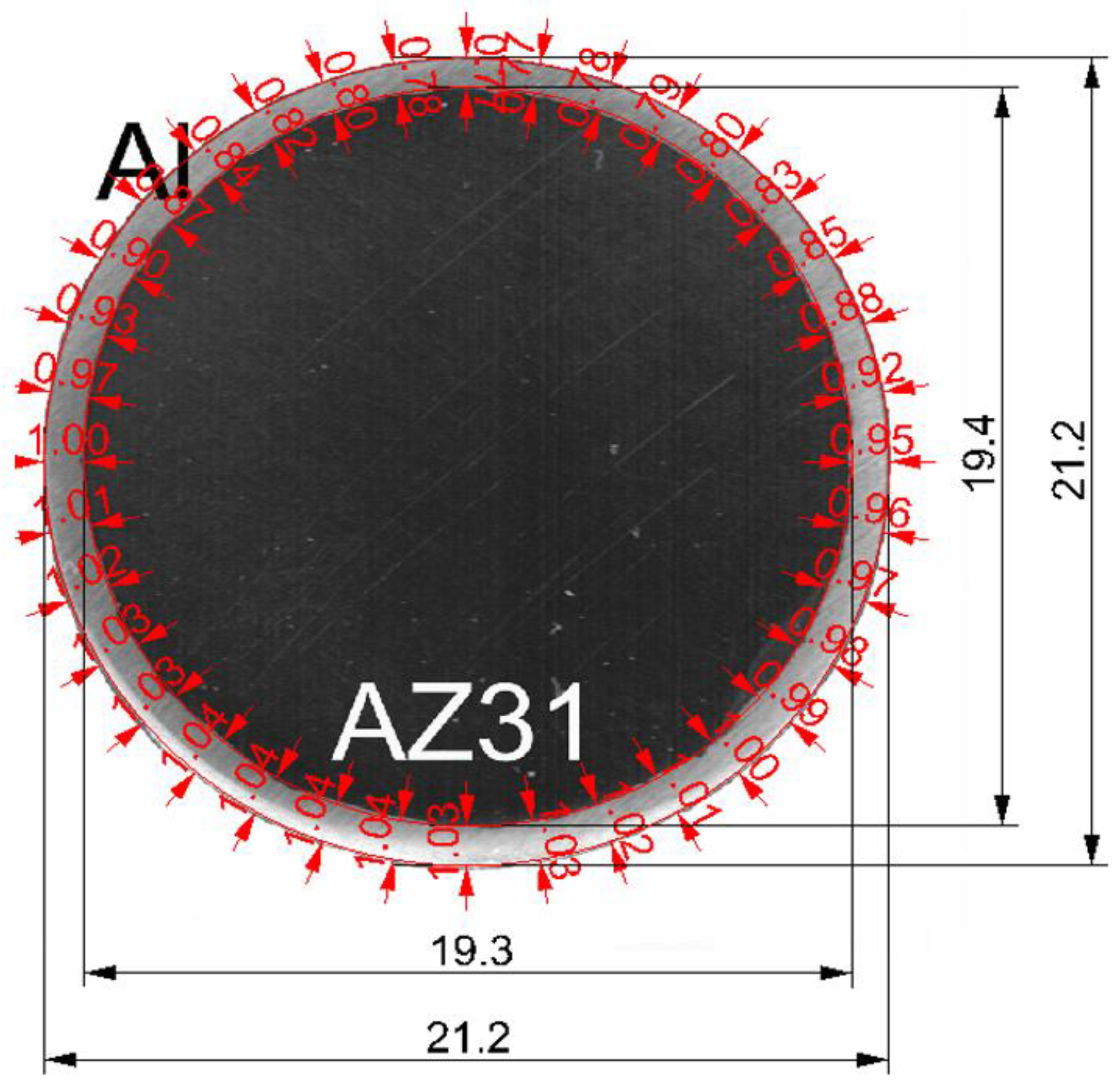
| Average External Diameter [mm] | Average Proportion of Al Layer in the Cross-Section [%] | Average Thickness of Al Layer [mm] |
|---|---|---|
| 21.2 | 16.8 | 0.93 ± 0.02 |
| Type of Material | Sample Designation |
|---|---|
| Aluminium alloy AA1050 | 100% Al |
| Magnesium alloy AZ31 | AZ31 |
| Bimetals form after explosive welding | −AZ31 + 15%Al |
| Bimetals after classical rolling, respectively at 300 °C or 400 °C—Variant I | Series I—rolling temperature: 300 °C Series II—rolling temperature: 400 °C |
| Bimetals after modified rolling, respectively at 300 °C or 400 °C—Variant II | Series III—rolling temperature: 300 °C Series IV—rolling temperature: 400 °C |
| Temp. | Constituting | Bimetallic Rods | Variant I—Classical Rolling | Variant II—Modified Rolling | Changes | |||
|---|---|---|---|---|---|---|---|---|
| [°C] | [%] | Average thickness of the layer [mm] | Kplat | Average thickness of the layer [mm] | Kplat | Average thickness of the layer [mm] | Kplat | [%] |
| 300 | 15 | 0.93 | 1.351 | 0.78 | 1.444 | 0.79 | 1.36 | 6.4 |
| 400 | 15 | 0.93 | 1.351 | 0.73 | 1.574 | 0.76 | 1.51 | 4.1 |
| Material/Rolling | Rolling Temperature | Ecor, [V] | ia [mA·cm−2] | Rp [Ω·cm2] | icor [mA·cm−2] |
|---|---|---|---|---|---|
| AZ31 | −1.6 | 260 | 60 | 860 × 10−3 | |
| Variant I | 300 °C | −0.86 | 1.5 × 10⁻² | 30 × 103 | 1.7 × 10⁻³ |
| 400 °C | −0.78 | 0.6 × 10⁻² | 50 × 103 | 1.1 × 10⁻³ | |
| Variant II | 300 °C | −0.75 | 6.0 × 10⁻² | 5.8 × 10³ | 8.9 × 10⁻³ |
| 400 °C | −0.63 | 6.5 × 10⁻² | 20 × 103 | 2.6 × 10⁻³ | |
| 1050 A | −0.53 | 6.0 × 10⁻² | 5.5 × 10³ | 9.5 × 10⁻³ |
Disclaimer/Publisher’s Note: The statements, opinions and data contained in all publications are solely those of the individual author(s) and contributor(s) and not of MDPI and/or the editor(s). MDPI and/or the editor(s) disclaim responsibility for any injury to people or property resulting from any ideas, methods, instructions or products referred to in the content. |
© 2023 by the authors. Licensee MDPI, Basel, Switzerland. This article is an open access article distributed under the terms and conditions of the Creative Commons Attribution (CC BY) license (https://creativecommons.org/licenses/by/4.0/).
Share and Cite
Mróz, S.; Jagielska-Wiaderek, K.; Stefanik, A.; Szota, P.; Wachowski, M.; Kosturek, R.; Lipińska, M. Effect of the Rolling Process on the Properties of the Mg/Al Bimetallic Bars Obtained by the Explosive Welding Method. Materials 2023, 16, 6971. https://doi.org/10.3390/ma16216971
Mróz S, Jagielska-Wiaderek K, Stefanik A, Szota P, Wachowski M, Kosturek R, Lipińska M. Effect of the Rolling Process on the Properties of the Mg/Al Bimetallic Bars Obtained by the Explosive Welding Method. Materials. 2023; 16(21):6971. https://doi.org/10.3390/ma16216971
Chicago/Turabian StyleMróz, Sebastian, Karina Jagielska-Wiaderek, Andrzej Stefanik, Piotr Szota, Marcin Wachowski, Robert Kosturek, and Marta Lipińska. 2023. "Effect of the Rolling Process on the Properties of the Mg/Al Bimetallic Bars Obtained by the Explosive Welding Method" Materials 16, no. 21: 6971. https://doi.org/10.3390/ma16216971
APA StyleMróz, S., Jagielska-Wiaderek, K., Stefanik, A., Szota, P., Wachowski, M., Kosturek, R., & Lipińska, M. (2023). Effect of the Rolling Process on the Properties of the Mg/Al Bimetallic Bars Obtained by the Explosive Welding Method. Materials, 16(21), 6971. https://doi.org/10.3390/ma16216971