Abstract
The superconducting joints of superconducting in situ MgB2 wires have been of great interest since the first MgB2 wires were manufactured. The necessity of joining fully reacted wires in applications such as NMR brings complexity to the methodology of connecting already reacted wires sintered under optimised conditions via a mixture of Mg + 2B and subsequential second heat treatment to establish fully superconducting MgB2 joints. Some of the data in the literature resolved such a procedure by applying high cold pressure and sintering at a low temperature. A topical review publication did not address in depth the question of whether cold sintering is a potential solution, suggesting that hot pressing is the way forward. In this paper, we discuss the potential joint interfacial requirements, suggesting a thermo-mechanical procedure to successfully form a superconductive connection of two in situ reacted wires in the presence of Mg + 2B flux. The critical current at 25 K of the researched junction achieved 50% Ic for an individual in situ wire.
1. Introduction
The superconducting joints of superconducting in situ MgB2 wires have been of great interest [1,2,3] since the first MgB2 wires were manufactured [4,5,6]. Persistent current joints between technological superconductors were the subject of a topical review [7] in which the authors discussed in depth the joint manufacture techniques for five major technological superconductors: NbTi, Nb3Sn, MgB2, Bi2Sr2Ca2Cu3Ox, and RE-Ba2Cu3O7−x. It was suggested by the authors of [3], that the melting point of MgB2 is high, and at high temperatures the compound tends to decompose into non-superconducting compounds, so the heating and recrystallising of reacted MgB2 wires is not an effective method for forming high-quality superconducting joints. Also, it was indicated that applying high pressure at room temperatures is similarly ineffective, as MgB2 is a brittle ceramic, much harder than the metal sheath materials. Both of the above conclusions are debatable and questionable. In the earlier technique of making joints between ex situ MgB2 wires via in situ Mg + 2B jointing, presented by [8], ex situ wires inserted into a Mg + 2B chamber did not show superconductivity in a 10 K self-field and showed only very weak superconductivity at 4.2 K when sintered at 640–670 °C; they were non-superconducting if sintered at temperatures below or above this range of temperatures. These disappointing results were due to procedural experimental mistakes, not a principally unachievable rule.
Instead of cold pressing the Mg + B precursor powder, followed by heat-treatment at ambient pressure, the author of [9] used a hot-pressing technique to produce a dense, filler material. On the other hand, hot pressing may not be most convenient method of making joints in an industrial environment; therefore, using our experience with cold deformation and the densification of joints [1], as well as optimisation expertise in the co-sintering of hybrid MgB2 in situ wire in direct contact with an ex situ barrier [10,11,12], in the present study, we attempt, based on the Mg–B binary phase diagram and the formation kinetics of MgB2, to define interfacial conditions for the thermo-mechanical formation of fully reacted MgB2 wires and secondary higher-temperature sintering in the presence of Mg + 2B.
2. Materials and Methods
Single-core in situ wires with an OD of 0.7 mm were manufactured according to a standard in situ procedure, as previously described in detail [13]. It was established that a short sintering time at ~700 °C was sufficient to achieve good performance for the in situ wires used. The architecture of the joint is schematically presented in Figure 1.
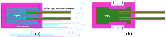
Figure 1.
Schematic of the adopted joint architecture: (a) assembled in situ reacted MgB2 wires inside a capsule filled with pre-compressed Mg+2B mixture of the same composition used for the manufacture of the wires [13]; (b) junction from Figure 1a after 0.5 GPa uniaxial compression in the joining area and sintering at 900 °C for 30 min, followed by cooling, as described in the text.
After filling the joining chamber with Mg+2B powder mixture (of the same composition as that used for the manufacture of the wires), the joined part of the two wires was fixed in place relative to the capsule (effectively preventing lateral movement of the constituting wires) for protection and to enhance the mechanical strength. For further strengthening and improvement of the density of the joined part, as well as to create localised subchannels for the diffusion of Mg into the already-formed MgB2 wire cores and intragranular microcracks (to be explained in the bulk of the text), the joint was uniaxially compressed to a pressure of up to 0.5 GPa perpendicularly to the contacting core-containing zone (Figure 1b). Finally, the joint was inserted into a furnace with an Ar protective atmosphere at ambient pressure for heat treatment at a sintering temperature of 900 °C; the sintering duration was 30 min. Afterwards, the samples were cooled down to room temperature in the furnace with an adjusted dwelling time at 650 °C. The sintering temperature and the duration were chosen according to the Mg–B binary phase diagram, and the heat treatment conditions were chosen according to the in situ PIT prepared wires used here.
Generally, Ic(T, B) measurements of the joints and wires under investigation are conducted versus the cooling temperature and external magnetic flux density in a dedicated system developed to minimise the use of He under dynamic cooling conditions [14]. The Ic defining electric field (E) criterion used was E = 1 μV/cm, both for the length unit of the optimised wire and for the resulting joining distance between the wire ends. For this material development paper, only representative, comparative Ic data for the wire and resulting joint are provided at 25 K in a self-field.
Knowledge of the Mg–B binary phase diagram is very important for the synthesis of superconducting MgB2 composites, wires, and joints, especially if complex problems of diffusive formation and re-bonding at the interface between the already-reacted in situ wire and the in situ filler during the second co-sintering need to take place. It is important to realise that in such a case, if the in situ reacted wire is subjected to compression and deformation and the re-establishment of its intergrain MgB2 connectivity, it is a problem of re-sintering “ex situ” material in contact with the in situ capsule material; this not only adds nomenclatural difficulties to describe the individual stages of the reactive diffusion processes but, most importantly, also poses complex material science problems to be correctly defined, analysed, and resolved.
Some of the Mg–B phase diagrams presented in the literature can provide uncertain ranges of decomposition temperatures for magnesium boride phases such as ex situ MgB2.
The reported decomposition reaction temperature range of boride phases such as
2MgB2(s) ⇒ MgB4(s) + Mg(g) is 850 °C ≤ Tdecomp (MgB2) ≤ 1550 °C [15].
The CALPHAD method and ab initio calculations were conducted by [15] to compute thermodynamic model parameters to determine the decomposition temperatures of magnesium borides and update the Mg–B binary phase diagram (see Figure 2). The planning of the sintering procedure of the “ex situ” (already in situ reacted) wires in the in situ joint capsule was based on the resulting Mg–B binary phase diagram in the present manuscript. It is important to note that based on the findings, the boundary between Mg(s) + MgB2 and Mg(g) + MgB2, as well as the MgB2 + MgB4 zone, on the elaborated phase diagram remains unchanged irrespective of the external pressure within the range 0.1–100 MPa.
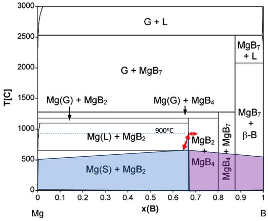
Figure 2.
Mg–B binary phase diagram from [15]. The shaded area represents the availability of Mg and B for the filler reaction process after junction compression to 0.5 GPa. The horizontal “reversible” arrow represents discussion of MgB2 and MgB4 interformation presented in Section 3.1. The vertical “reversible” arrow represents an excess of Mg at the initial stage of sintering of the joints and solid-state diffusion of the joints during cooling presented in Section 3.2.
3. Results
Before we come to presentation of microstructural and current transport results, aspects of possible parallel important events taking place must be discussed to underline the influences on the chosen process and results. The thermo-mechanical processes taking place during joint formation at the interface between the in situ sintered lower-density elongated MgB2 structure of the wires and the Mg + 2B ⇒ MgB2 filler have two fundamental aspects, detailed as follows.
3.1. Induced Interfacial Change and Phase Transformation
There is a potential change in phase transformation chemistry at the open ends of the MgB2 conductor prepared by angular grinding (to maximise the exposure of the MgB2 to a potential joining reaction, which could induce local loss of Mg, thus making it prone to decomposition via 2MgB2(s) ⇒ MgB4(s) + Mg(g)); see Figure 2.
As pointed out by [16], the thermodynamic decomposition of MgB2 takes place under a low Mg partial pressure [17] via 2MgB2(s) ⇒ MgB4(s) + Mg(g). Such a decomposition of MgB2 was experimentally observed as the loss of gaseous Mg at temperatures as low as 610 °C [18]. Importantly, a sintering experiment conducted on MgB4 additives to in situ (Mg + 2B) materials [19] revealed a positive effect of such additions at a small percentage (up to 10 wt%). A MgB2 sample made by an in situ process at 775 °C for 3 h with 2 wt% of MgB4 powder showed a 40% higher critical current density at 25 K in a self-field than did the pure MgB2 sample. However, further increase of the MgB4 powder content up to 10 wt% caused a systematic reduction in the Jc(B,T), but not below the actual value for the pure MgB2 sample. The excessive loss of Mg at 900 °C in the unprotected interface causes the rapid formation of MgB4, which causes degradation of the superconducting properties [20].
As shown by [16], ex situ samples heated at moderately high temperatures of 900 °C for a longer period showed an increased packing factor, a larger intergrain contact area, and significantly decreased resistivity, all of which indicate the solid-state self-sintering of MgB2.
In conclusion, some interfacial MgB4 formation can take place, freeing Mg vapour and facilitating the healing of microcracks; however, such a process can be localised and can be reversed by excess Mg originating from the Mg + 2B filler, as will be discussed in Section 3.2.
3.2. Recompaction and Recombination in the Wire–Filler Bond
Considering that the contact area between MgB2 grains in the ex situ bulk is limited by the porosity, intergrain coupling is still considered insufficient compared with that in the in situ bulk. Thus far, the connectivity of ex situ MgB2 is a trade-off between the higher packing factor and the weaker intergrain coupling. The authors of [16] predicted a high connectivity of 30–40% for moderately sintered ex situ MgB2 with a packing factor (PF) of 75%. It was calculated that an approximately 25% increase in PF compared with that in in situ MgB2 results in up to three times higher connectivity in ex situ MgB2 if a sufficient arrangement of surface contact between grains is achieved, for example, by compressing the matrix to 0.5 GPa, re-deforming the grain structure of the MgB2 wires [1]. Such procedure would, under a controlled atmosphere of Mg pressure sourced from Mg + 2B, promote the solid-state self-sintering of MgB2 and significant improvements in intergrain coupling by heat treatment under ambient pressure; additionally, the reversible process MgB4(s) + Mg(g) ⇒ 2MgB2(s) can take place, see Figure 2.
It was reported in the literature [21] that ex situ and in situ samples sintered at 900 °C for 24 h show similar Jc(0 T, 20 K) values, indicating that exposure of the in situ joint in the presence of ex situ wires is a correct approach to the manufacture of superconducting joints. However, the Jc value in the presence of an external magnetic field is superior for the ex situ wires; this is less important for the joints, which are normally shielded from the magnetic field of the application electromagnet, such as MRI magnets. Clear evidence for strongly connected ex situ MgB2 polycrystalline bulks fabricated by solid-state self-sintering (at 900 °C) [21] formed a basis for planning the sintering of the researched joints at 900 °C for 30 min and cooling them to 650 °C to allow residual magnesium vapour to penetrate the residual interfacial nonuniformities (Figure 2).
The partial pressure of the Mg vapour in the closed environment at the interface between ex situ MgB2 and in situ Mg + 2B (where the complex process of reactive diffusion formation (in situ) of MgB2 accompanied by possible MgB2 (ex situ) localised decomposition to MgB4, releasing Mg and partially re-forming back to MgB2, takes place) is essential for the integrity of the superconducting joint to be formed. The high-temperature vaporisation thermochemistry of the intermediate phases in the B-rich portion of the Mg–B phase diagram from MgB2 to MgB20 was extensively studied by [22], who provided assessment data for the biphasic region where MgB4(s) = MgB2(s) + Mg(g).
3.3. Results of Thermo-Mechanical Processes Joint Formation
Considering the above discussed necessity of powder compaction of the already formed MgB2 material in the wires, a cold uniaxial deformation process of the capsulated joint set-up was adopted (Figure 1b). This rearranged the MgB2 grains close to induced cracks, enable better accessibility of Mg vapour to promote diffusion bonding of the wires with Mg + 2B joint filler. The resulting morphology and microstructure of the jointing MgB2 materials are presented in Figure 3a. The critical current measurement of the representative final joint in a dynamically cooled flow cryostat at 25 K was 50 A, while for the wire, the value was 100 A.
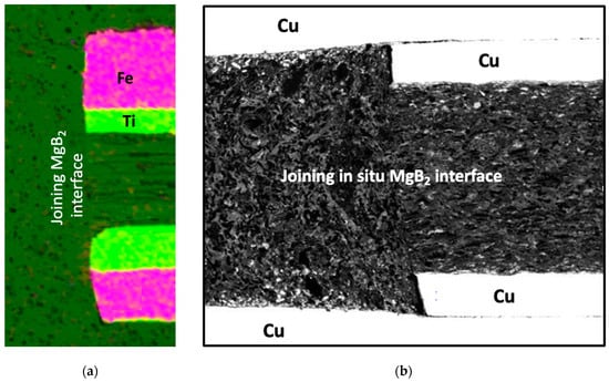
Figure 3.
SEM image of the cross-sectional interface between the wire and filler in the joining capsule. (a) EDAX current work; the OD of the wire was 0.7 mm. The different morphology of the wire core and the filling material can be observed at the actual joining interface. The fibre-like structure of the original wire induced by cold deformation of the powder is pronounced, whereas the filler matrix looks very uniform. A deep green colour represents MgB2. (b) For comparison, the cross-sectional microstructure of the initial fully in situ joint formation is presented [1], where electromagnetic compaction created a distinctive buckling effect on the interfacial region between the wire and the filler, which is not observed in Figure 3a. The above comparison of morphological differences of the fibre-like ex situ wire in a rigid in situ capsule and the in situ wire in contact with in situ filler powder reveals the complexity of the deformation processes taking place in various joints. An important fact is that the Ic value for the joint presented in Figure 1b was only 15% that for the wire (at 25 K self-field).
4. Discussion and Conclusions
The presented positive results reflect an analysis of the possible interfacial and localised complex processes of formation of in situ joints with already manufactured in situ wires. Further analysis of the deformation processes and actual sintering reformation and formation processes based on reactive diffusion processes in the presence of Mg liquid and gas forms requires further research efforts to achieve reproducible joints with greater Jc properties.
It is important to realise that in the proposed case, if the in situ reacted wire is subjected to compression and deformation and the reestablishment of MgB2 intergrain connectivity, it becomes a problem of sintering “ex situ” material not strictly in situ (material that, however, was in situ before the reaction), which introduces not only nomenclatural difficulties to describe but also, most importantly, complex material science problems to be correctly analysed and resolved. As reliable and reproducible joints are needed for applications, in-depth research will continue.
Funding
This research received no external funding.
Institutional Review Board Statement
This study did not require ethical approval.
Informed Consent Statement
Not applicable.
Data Availability Statement
On request.
Acknowledgments
The author would like to thank the Materials Science Department for SEM images.
Conflicts of Interest
There are no conflicts of interest.
References
- Wozniak, M.; Glowacki, B.A.; Setiadinata, S.B.; Thomas, A.M. Pulsed magnetic field assisted technique for joining MgB2 conductors for persistent mode MRI magnets. IEEE Trans. Appl. Supercond. 2013, 23, 6200104. [Google Scholar] [CrossRef]
- Patel, D.J. Design and Fabrication of Solid Nitrogen Cooled MgB2 based Persistent Magnet for MRI Application. Ph.D. Thesis, University of Wollongong, Wollongong, NSW, Australia, November 2016. Available online: https://ro.uow.edu.au/cgi/viewcontent.cgi?article=5774&context=theses (accessed on 9 August 2016).
- Li, X.H.; Ye, L.Y.; Jin, M.J.; Du, X.J.; Gao, Z.S.; Zhang, Z.C.; Kong, L.Q.; Yang, X.L.; Xiao, L.Y.; Ma, Y.W. High critical current joint of MgB2 tapes using Mg and B powder mixture as flux. Supercond. Sci. Technol. 2008, 21, 025017. [Google Scholar] [CrossRef]
- Glowacki, B.A.; Majoros, M.; Vickers, M.; Evetts, J.E.; Shi, Y.; McDougall, I. Superconductivity of powder-in-tube MgB2 wires. Supercond. Sci. Technol. 2001, 14, 193–199. [Google Scholar] [CrossRef]
- Glowacki, B.A.; Majoros, M.; Vickers, M.; Eisterer, M.; Toenies, S.; Weber, H.W.; Fukutomi, M.; Komori, K.; Togano, K. Composite Cu/Fe/MgB2 superconducting wires and MgB2/YSZ/Hastelloy coated conductors for ac and dc applications. Supercond. Sci. Technol. 2003, 16, 297–305. [Google Scholar] [CrossRef]
- Glowacki, B.A.; Majoros, M.; Tanaka, K.; Kitaguchi, H.; Kumakura, H.; Okada, M.; Hirakawa, M.; Yamada, H.; Hancock, M.H.; Bay, N. Critical current and cryogenic stability modelling of filamentary MgB2 conductors. J. Phys. Conf. Ser. 2006, 43, 103–106. [Google Scholar] [CrossRef]
- Brittles, G.D.; Mousavi, T.; Grovenor, C.R.M.; Aksoy, C.; Speller, S.C. Persistent current joints between technological superconductors. Supercond. Sci. Technol. 2015, 28, 093001. [Google Scholar] [CrossRef]
- Yao, W.; Bascuñán, J.; Hahn, S.; Iwasa, Y. A superconducting joint technique for round wires. IEEE Trans. Appl. Supercond. 2009, 19, 2261–2264. [Google Scholar] [PubMed]
- Oomen, M.P. Superconducting Joints between MgB2 Wires for MRI Applications. In Proceedings of the Applied Superconductivity Conference, Charlotte, NC, USA, 10–15 August 2014. [Google Scholar]
- Glowacki, B.A.; Morawski, A. U.S. Patent 2008/0274901 A1; Composite Electrical Conductors and Method for their Manufacture. World Intellectual Property Organization: Geneva, Switzerland, 2008. Available online: http://patentimages.storage.googleapis.com/1b/3f/5e/8f736a1b93aa62/WO2008122802A1.pdf (accessed on 10 July 2023).
- Kario, A.; Morawski, A.; Hassler, W.; Herrmann, M.; Rodig, C.; Schubert, M.; Nenkov, K.; Holzapfel, B.; Schultz, L.; Glowacki, B.A.; et al. Novel ex situ MgB2 barrier for in situ monofilamentary MgB2 conductors with Fe and Cu sheath material. Supercond. Sci. Technol. 2010, 23, 025018. [Google Scholar] [CrossRef]
- Glowacki, B.A.; Nuttall, W.J. Assessment of liquid hydrogen cooled MgB2 conductors for magnetically confined fusion. J. Phys. Conf. Ser. 2008, 97, 012333. [Google Scholar] [CrossRef]
- Glowacki, B.A.; Kutukcu, M.N.; Atamert, S.; Dhulst, C.; Mestdagh, J. Formation of Mg2Si inclusions in in situ SiC doped MgB2 wires made from variable concentration of large micrometer-size Mg powder by continuous method. IOP Conf. Ser. Mater. Eng. 2019, 502, 012176. [Google Scholar] [CrossRef]
- Baskys, A.; Hopkins, S.C.; Bader, J.; Glowacki, B.A. Forced flow He vapor cooled critical current testing facility for measurements of superconductors in a wide temperature and magnetic field range. Cryogenics 2016, 79, 1–6. [Google Scholar] [CrossRef]
- Kim, S.; Donald, S.; Stone, D.S.; Cho, J.I.; Jeong, C.Y.; Kang, C.S.; Bae, J.C. Phase stability determination of the Mg–B binary system using the CALPHAD method and ab initio calculations. J. Alloys Compd. 2009, 470, 85–89. [Google Scholar] [CrossRef]
- Yamamoto, A.; Tanaka, H.; Shimoyama, J.J.; Ogino, H.; Kishio, K.; Matsushita, T. Towards the realization of higher connectivity in MgB2 conductors: In-situ or sintered ex-situ? Jpn. J. Appl. Phys. 2012, 51, 010105. [Google Scholar] [CrossRef]
- Liu, Z.K.; Zhong, Y.; Schlom, D.G.; Xi, X.X.; Li, Q. Computational thermodynamic modeling of the Mg-B system. Calphad 2001, 25, 299–303. [Google Scholar] [CrossRef]
- Brutti, S.; Ciccioli, A.; Balducci, G.; Gigli, G.; Manfrinetti, P.; Palenzona, A. Vaporization thermodynamics of MgB2 and MgB4. Appl. Phys. Lett. 2002, 80, 2892–2894. [Google Scholar] [CrossRef]
- Ishiwata, J.; Muralidhar, M.; Inoue, K.; Murakami, M. Effect of MgB4 addition on the superconducting properties of polycrystalline MgB2. Phys. Procedia 2015, 65, 69–72. [Google Scholar] [CrossRef]
- Yakinci, M.E.; Balci, Y.; Aksan, M.A.; Adiguzel, H.I.; Gencer, A. Degradation of superconducting properties in MgB2 by formation of the MgB4 phase. J. Supercond. 2002, 15, 607–611. [Google Scholar] [CrossRef]
- Tanaka, H.; Yamamoto, A.; Shimoyama, J.I.; Ogino, H.; Kishio, K. Strongly connected ex situ MgB2 polycrystalline bulks fabricated by solid-state self-sintering. Supercond. Sci. Technol. 2012, 25, 115022. [Google Scholar] [CrossRef]
- Balducci, G.; Brutti, S.; Ciccioli, A.; Gigli, G.; Manfrinetti, P.; Palenzona, A.; Butman, M.F.; Kudin, L. Thermodynamics of the intermediate phases in the Mg–B system. J. Phys. Chem. Solids 2005, 66, 292–297. [Google Scholar] [CrossRef]
Disclaimer/Publisher’s Note: The statements, opinions and data contained in all publications are solely those of the individual author(s) and contributor(s) and not of MDPI and/or the editor(s). MDPI and/or the editor(s) disclaim responsibility for any injury to people or property resulting from any ideas, methods, instructions or products referred to in the content. |
© 2023 by the author. Licensee MDPI, Basel, Switzerland. This article is an open access article distributed under the terms and conditions of the Creative Commons Attribution (CC BY) license (https://creativecommons.org/licenses/by/4.0/).