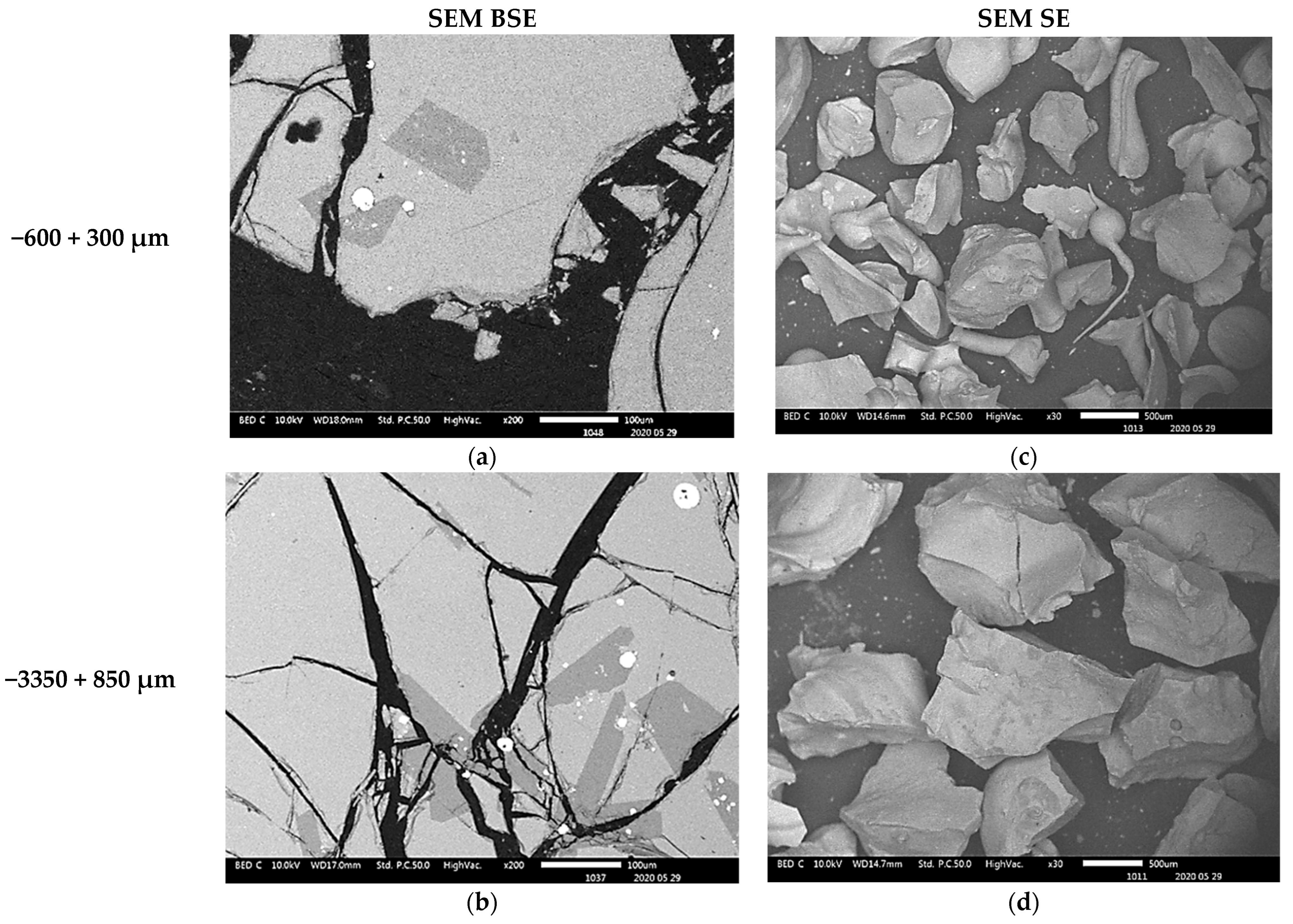
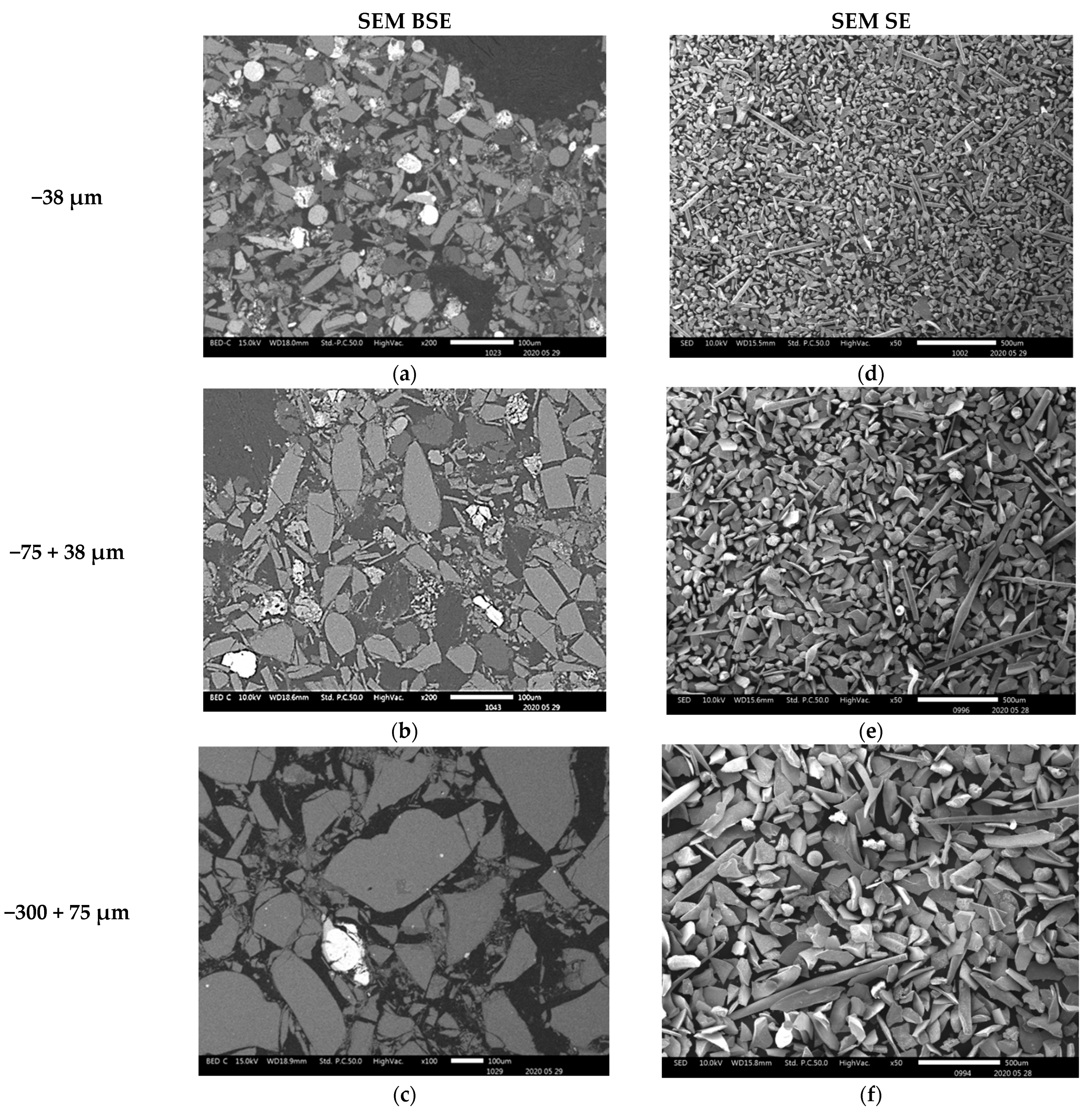
3.3.1. Scanning Electron Microscopy
The compositional contrast observed in backscattered (BSE) mode images (
Figure 3a–c,
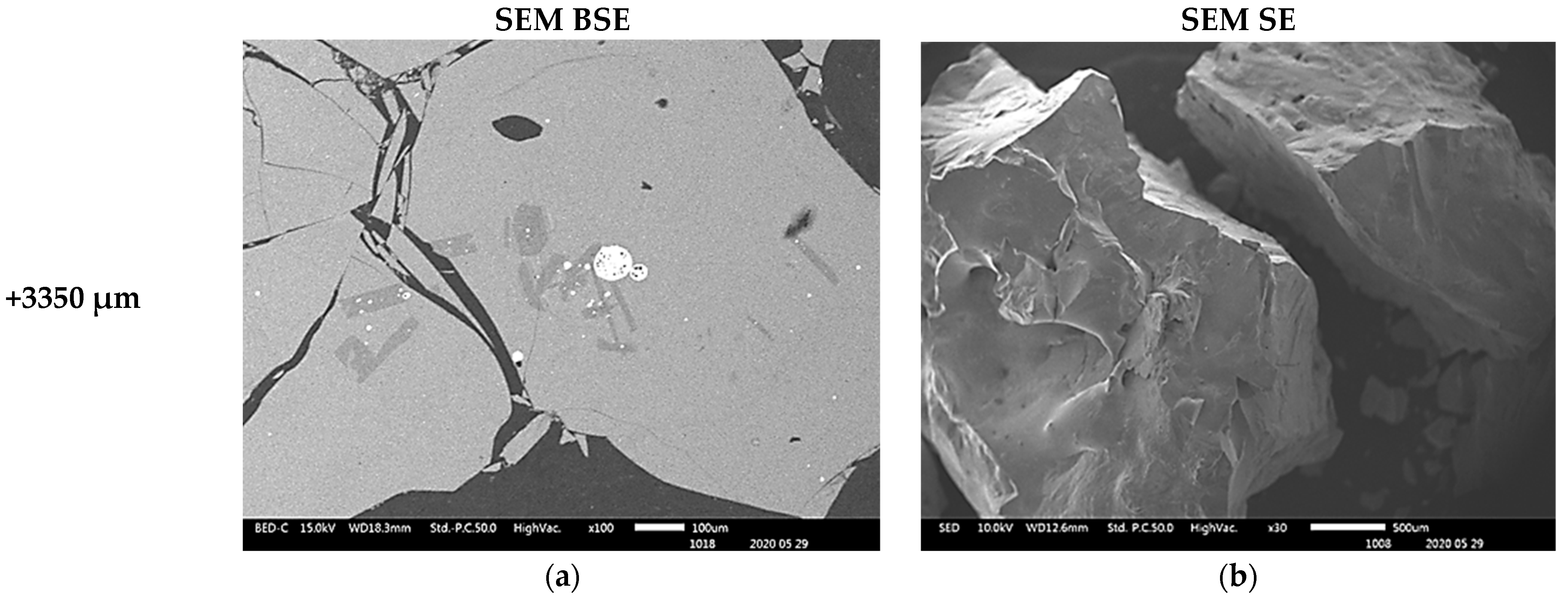
Figure 4a,b and
Figure 5a) indicate that higher proportions of particles of material phases containing the heavy elements were found in the fine particles (−38 µm and −75 + 38 µm). The proportion of the phases of heavy elements is lower in the particles coarser than 300 µm. SEM BSE also revealed that the particles of the heavy metal phases present in the fine granulometric size ranges were separated from the slag matrix particles (i.e., higher degree of liberation between particles of metallic and slag phases). The separation of these particles from the slag matrix is attributed to the non-miscibility between the molten slag and the metal compounds contained in the matte that were mechanically dragged when tapping the slag from the hearth zone of the smelting furnace.
The morphologies and sizes of the particles of the matte or metal phases and the slag matrix particles were investigated under secondary electrons (SE) mode observation in the SEM machine. The images of
Figure 3,
Figure 4 and
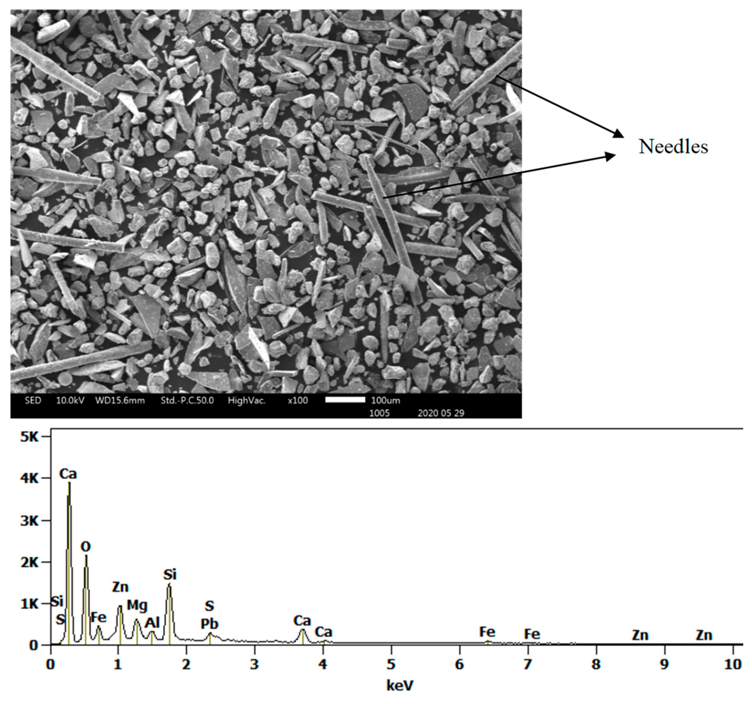
Figure 5 illustrate the actual shapes. The SEM SE images indicate higher proportion of the high aspect ratio (Length/Diameter) needle-like particles present in the finer materials of −38 µm (
Figure 3c). These needle-like particles are relatively coarser within the fine size material fraction, but their relative volumetric proportion in the slag material decreases as the granulometric size ranges increase in the −75 + 38 µm (
Figure 3d) and then in the −300 + 75 µm (
Figure 3f). Finally, no needle-like particles are observed in the coarse size ranges of slag material fractions above 300 µm (
Figure 4c,d and
Figure 5b). The nature and formation mechanism of the needle-like particles is discussed in the next section.
The scanning electron microscopy images show that the small particles of matte or metal phases (high reflectance) found in the coarse granulometric ranges, above 300 µm (
Figure 4 and
Figure 5), were rather trapped by occlusion inside the smelting liquid slag and solidified upon quenching in the high pressure water jet. Large slag particles have cracks that formed during the fast quenching in the water jet. The formation of the cracks is attributed to the low thermal conductivity of the slag [
41,
42,
43,
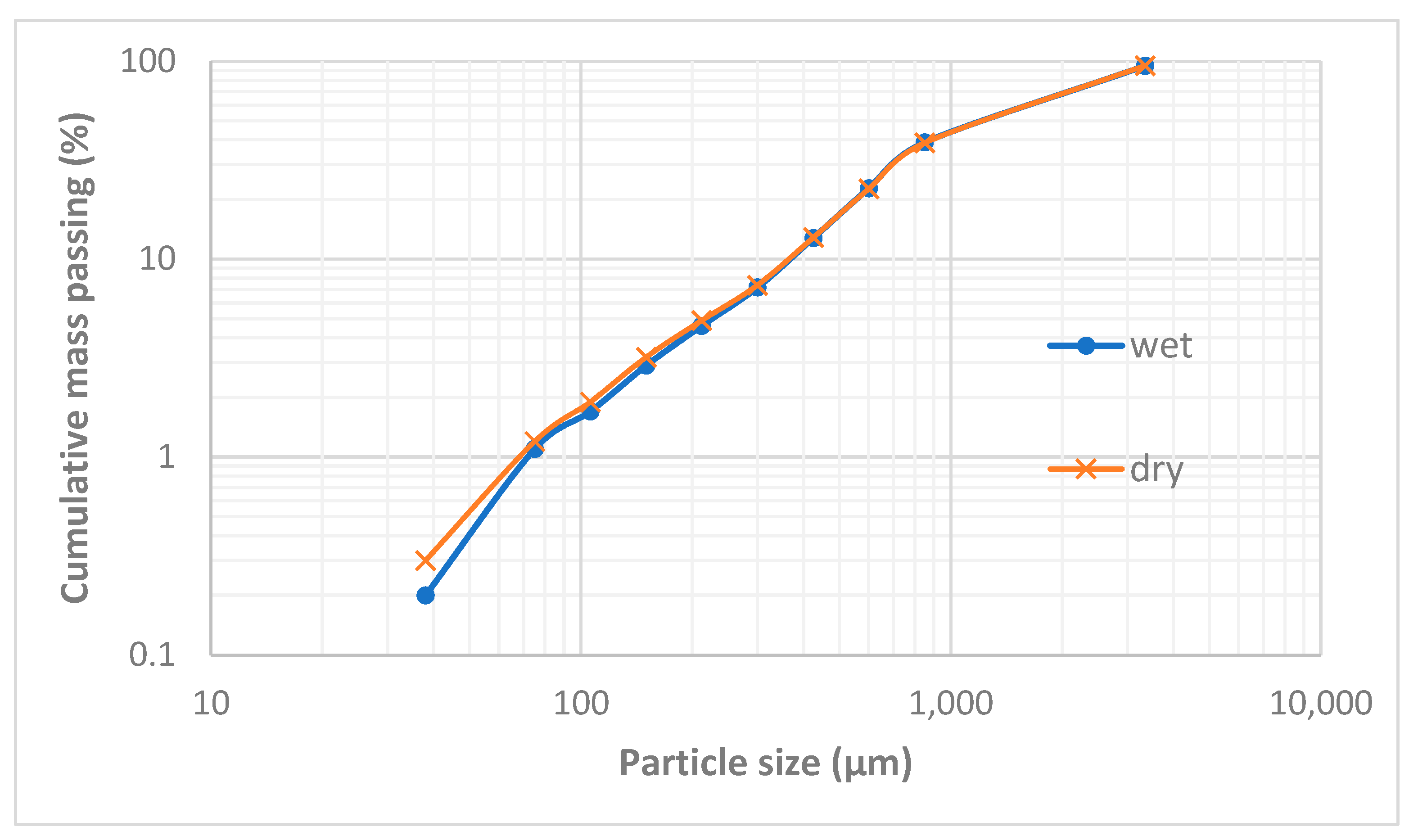
44] and the difference in coefficients of thermal expansion, thus shrinkage, between the slag and the matte (metal) phases, which result in thermal stresses inside the solidified material. The particle size distribution in
Figure 2 suggested that the materials of granulometric size larger than 300 µm represent about 90% (
w/
w) of the sample of the received historic slag material. It, therefore, implies that the major quantities of matte and metal phases, that were mechanically dragged with the slag, are trapped inside the slag particles larger than 300 µm but their concentration values in these large particles are lower than in the finer materials (<300 µm). The fine particle size ranges (<300 μm) represent only about 8% (
w/
w) of the historic smelter slag but with higher contents of matte and metal phases.
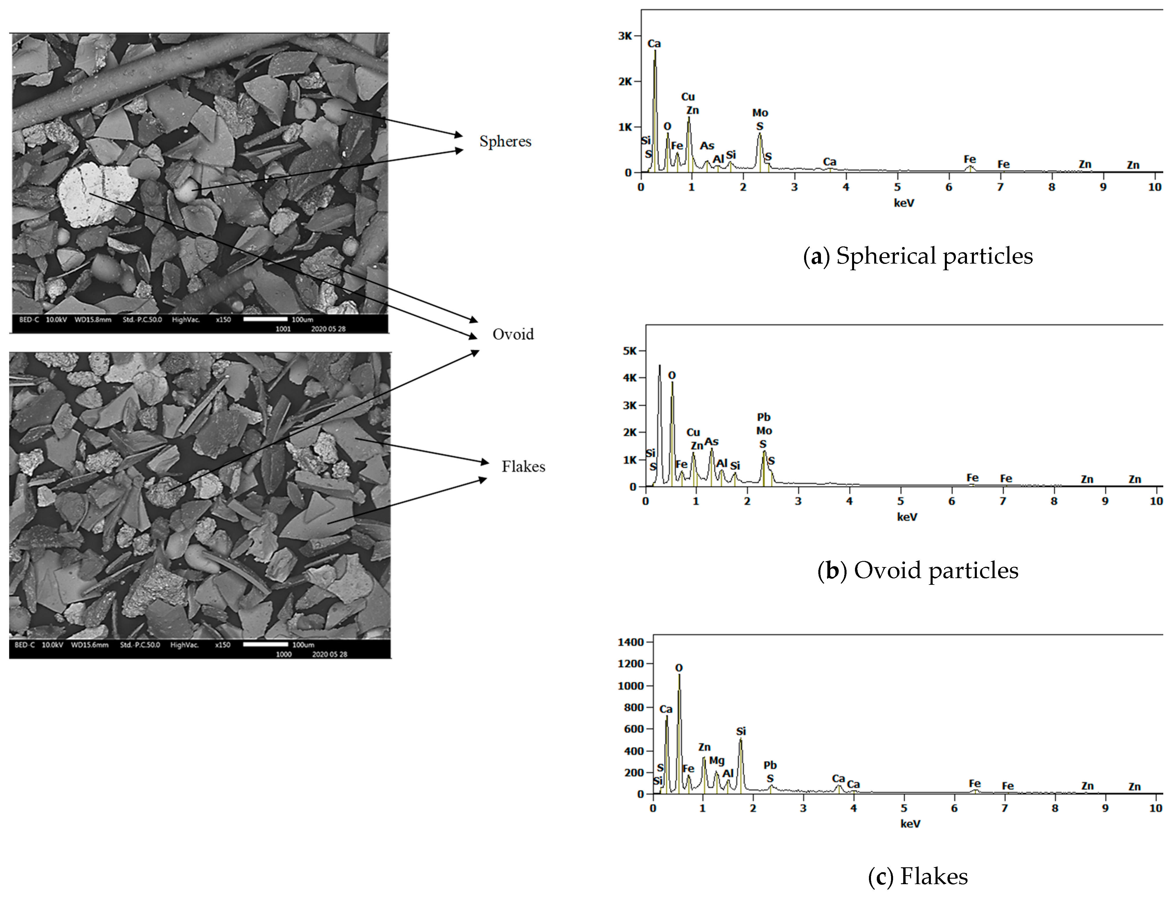
3.3.2. Morphology and Composition of Fine Particle Materials
The SEM SE observation of particles of the received slag sample material collected in granulometric ranges smaller than 300 µm revealed four types of particle shapes as shown in
Figure 6 and
Figure 7 (i.e., the flakes, the spheres with smooth surfaces, the needle-like particles, and the ovoid particles with rough surfaces). The SEM SE images of
Figure 6 and
Figure 7, infer that the flaky particles represent the main constituent of the slag materials in all particle size ranges obtained after sieving the historic slag material. The ovoid particles with rough surfaces are present in a wide size range from 30 to 200 µm. The SEM SE images suggest the ovoid particles are the second important phase present in the material passing the 300 µm sieves. The needle-like particles have aspect ratios (Length/Diameter) higher than 10. Such particles of length bigger than 500 µm have passed through the 38 µm sieve square apertures since their diameter is as small as 25–30 µm. The spherical particles compose the least proportion of phase found in the slag material that passed through the 300 µm sieves. They have a diameter range of 30–70 µm and are distinguishable from the ovoid particles by their smooth surface appearance under SEM SE mode.
Energy dispersive X-ray spectroscopy (EDS) analysis of these four types of particles in the slag sample indicates that they are different phases in compositions. Their corresponding composition ranges are given in
Table 3. The EDX method is considered as semi-quantitative, but has the advantage of evaluating the composition of selected grains or regions within the sample of materials under consideration. The method is not recommended for the quantification of light elements, and thus the oxygen contents only serve as qualitative indicators of the oxide phases present in the slag material. Similarly, the sulphur contents reveal the presence of the sulphide phases.
The results of the EDS area analysis of the particles of the slag materials infer the following:
The flaky particles (i.e., the main component of the solid slag) consist of metal oxide compounds or [(Fe, Ca, Mg, Zn, Al, Si) O]. The flake type of particles contain the highest zinc content of 11–15% (
w/
w) of all the particles present in the slag. The elemental mapping in
Figure 8 shows the preferential location of zinc inside the regions of the flake and needle-like shape particles. The flake type of particles have the lowest contents of sulphide formers Pb and Cu. The EDS analysis showed no peaks for arsenic and germanium in these particles.
The needle-like particles are also composed of the [(Fe, Ca, Mg, Zn, Al, Si) O] compounds, however with higher silicon and lead contents, and lower calcium content than those found the flakes. An acidity index (1) of the slag is introduced to compare the chemistry of the flake shape and the needle-like particles components of the historic slag material as follows:
The calculation yields values of the acidity index equal to 0.5 for the flakes and 1.2 for the needle-like particles of the slag material (i.e., the acidity index of the needles is more than double that of the flakes). This difference suggests that the molten slag in the smelting furnace contained at least two different liquid phases; one main liquid phase of the composition of the flakes and a second liquid phase, in smaller quantity, of the composition as the needle-like particles. The needles phases therefore are much higher in silica-rich phases than other shapes. This second liquid might have consisted of droplets or veins that formed the elongated needles (L > 500 µm) with fine cross section diameters (D < 75 µm) upon tapping and quenching of the slag in the high-pressure water jet. The higher acid index of the needle-like shape particles indicates the tendency of formation of polymeric silicates with tridimensional structures, which results in high viscosity of the molten slag phase. The coexistence of significant numbers of the needle-like particles with the flakes in the fine granulometric size ranges may be ascribed to the separation, due to lack of miscibility, of the two phases in liquid slag inside the hearth of the furnace. Some micron and sub-micron size particles, of similar appearance to the ovoid and spherical shape phase are trapped onto the surface of the needle-like particles, not onto the flake-shaped particles. It is inferred, therefore, that the high viscosity of the liquid phase of high acidity index (needle-like) hindered the decantation of the droplets of liquid sulphide (metal) phases through the hearth zone into the matte or metal phase.
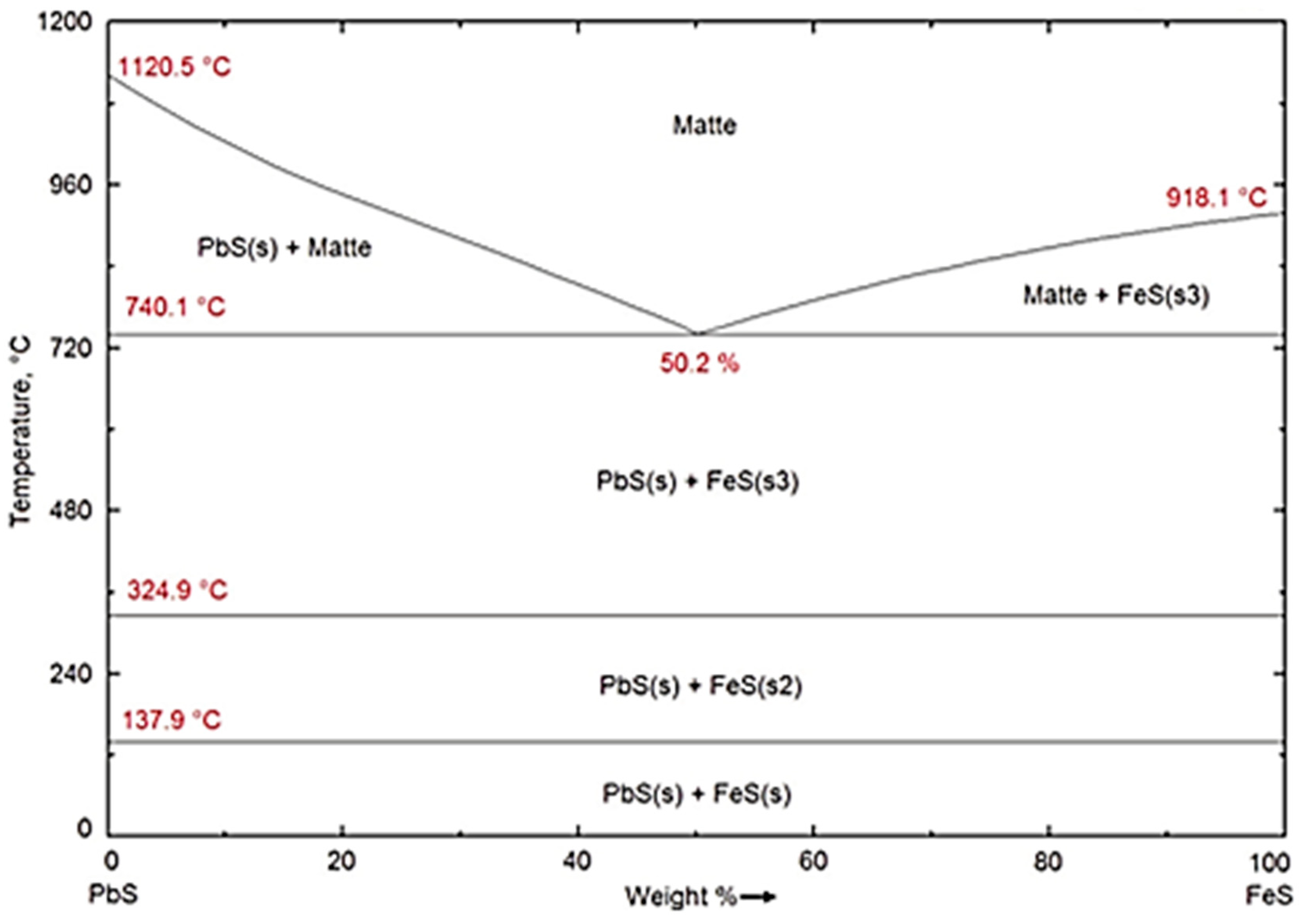
On the other hand, the ovoid particles are distinguishable by their rough surfaces and have very low contents in oxide formers Si, Ca, Fe Mg, Al, and Zn. They rather have the highest concentrations of Cu, Fe, As, and S along with the second highest content of Pb of all the four types of particles encountered in the historic slag material. It is concluded from the results of EDS analysis in
Table 3 that the ovoid particles consist of the sulphide compounds such as Cu
2S, FeS, PbS, and As
2S
3 that constituted the matte product in the smelter. The wide range of variation of the four elements Cu, Fe, Pb and As is ascribed to the heterogeneity within the ovoid shape particles due to the separation of non-miscible sulphides phases upon cooling. The calculated equilibrium phase diagrams in
Figure 9, show the lack of miscibility between PbS and the other sulphides such as FeS, Cu
2S or ZnS below 600 °C. The lack of miscibility with other sulphides and metals is also exploited as a means of producing high grade mattes and Pb metal in smelting furnace.
Finally, the spherical particles with smooth surfaces have the highest Pb content of all the four types of particles, which reaches 79% (
w/
w) in some areas, with relatively low sulphur. The strong oxygen peak infers that these particles consist of a mixture of PbO and Pb metal formed in the melt upon the conversion reactions (2) and (3). The spherical particles have dissolved some amounts of Si, Fe, As, and Zn. The appearance of these free particles in the slag material shows that their material is not miscible either with the liquid slag (flakes and needle-like particles materials) or with the sulphide material of the ovoid shape particles.
The EDS analysis suggested the presence of arsenic and germanium was in the sulphide constituents of the ovoid shape particles and in the high Pb content spherical particles. The Lα X-ray energies of germanium and arsenic are close to each other at 1.188 keV and 1.282 keV, respectively. The EDS method showed little selectivity between these two elements especially in the presence of low germanium concentration and low as expected in this case. This method of analysis suggests that arsenic and germanium are collected in the ovoid shape particles of the sulphide phases and more in the spherical particles of the (Pb, PbO, PbS) phase. The sulphide ovoid shape particles and the lead spherical particles would contain up to 1600 ppm and 6300 ppm germanium respectively. It should however be recalled here that according to the results of particle size classification, these particles and all the slag material passing the sieve at 300 µm represent about 8% (w/w) of the total mass of slag sample received. A conservative approach based on the estimation that those particles only represent 2% (w/w) of the slag material yield a germanium content within the range 32–126 ppm in the historic smelter slag received.
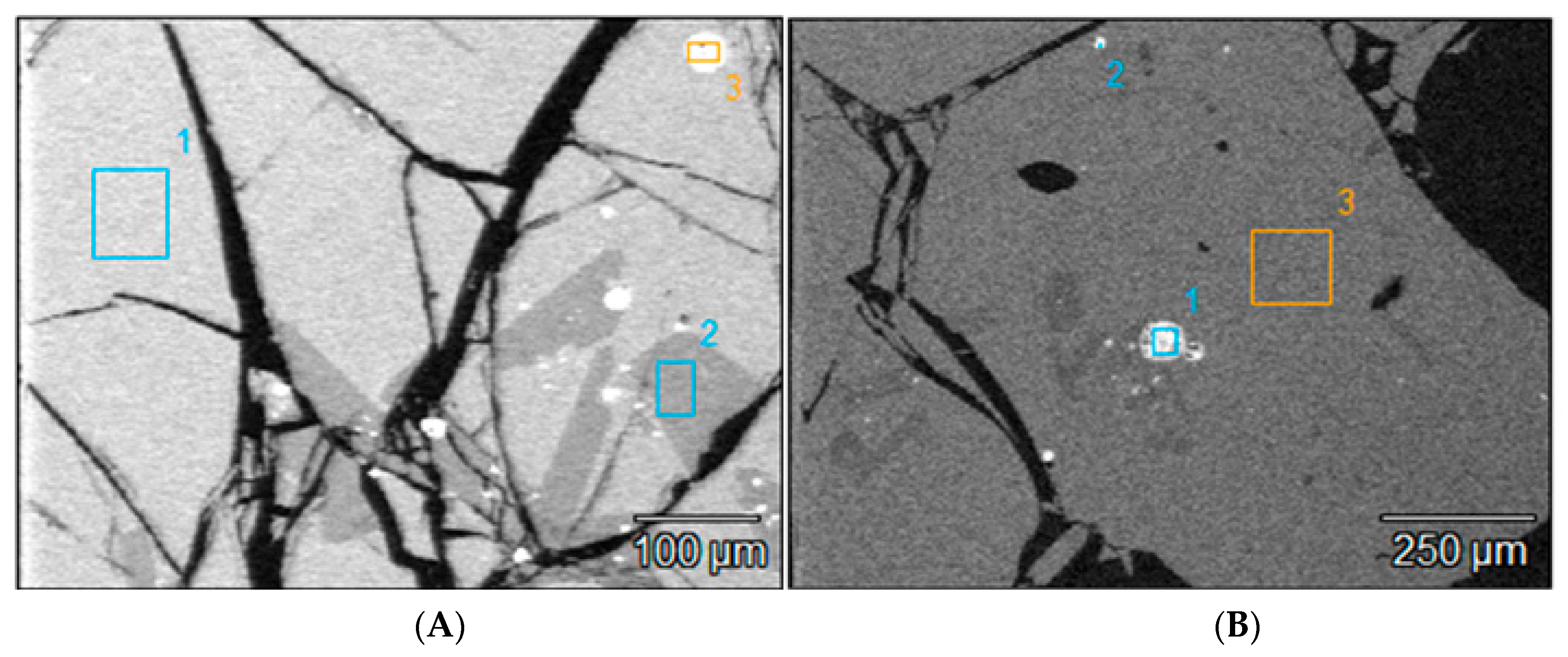
3.3.3. Morphology and Composition of Coarse Size (>300 µm) Slag Particles
The morphologies of the slag particles within the size ranges +300–600 µm, +600–850 µm, and +850–3350 µm are illustrated in
Figure 4 and
Figure 5. Unlike the fine particle size ranges (<300 µm) where flakes, needles, ovoid and spherical shape particles were found, the coarser particles are bulky and irregular multifaceted with multiple cracks. These coarse particles contain some amount of small particles of entrapped matte or metals as seen in the micrographs of the polished particles of sizes larger than 850 µm and 3350 µm which are shown in
Figure 10. The EDS chemical analysis of the phases present in these coarse slag particles (in
Table 4) indicates the presence of two slag phases and the small particles of matte or metal phases.
Table 4 shows that the matrix and the secondary phases of the bulky slag particles (>300 µm) have chemical composition ranges similar to that of the flaky particles found in the fine materials (<300 µm). It therefore infers that the formation of the small flakes resulted from grinding of the molten slag by the high-velocity flow water jet, whereas the coarse bulky slag particles were formed in the low-velocity flow regions of the water jet. Pressure and flow rate distribution inside the water jet determined the granulometric distribution of the solidified slag.
The secondary phase found in the coarse slag particles has slightly higher silicon and calcium contents, but lower Pb content than the main phase of the slag matrix. The matrix and the secondary phases of the coarse particles have acidity index 0.4 and 0.7 respectively, which are close to the acidity index i = 0.5 of the flake shape particles found in the fine material of the received sample of historic smelter slag. It was noticed earlier that the needle-like shape particles only formed at high acidity index 1.2, under high silicon content (37 wt%), which leads to the polymerisation of silicate structures. These silicates have higher viscosity at the slag melting temperature.
3.3.4. Optical Microscopy Analysis of the Slag Constituents
As a way of simplifying the process of identification, all phases identified are given names of natural equivalents. The process of slag formation leads also to the formation of glass and several silicate phases with specific shapes that have been identified both under the SEM and in optical microscopy. Glass is mainly silicate material that is formed when silicate melt is cooled rapidly. The petrography is better understood by realizing that in the slag development, free metal particles become droplets in the slag, and then cool down and tend to form spherical and ovoid shapes. The following sulphide phases have been identified: galena (PbS); wurtzite (ZnS); sphalerite (ZnS); chalcopyrite (CuFeS2); pyrrhotite (Fe1−xS); pyrite (FeS2); minor cubanite (CuFe2S3) and covellite (CuS). The silicates present include fayalite (Fe2SiO4), monticellite (CaMgSiO4), mellilite (Ca(Mg,Fe,Zn)Si2O7), anorthite (CaAl2Si2O8) and Pb-Plagioclase (PbAl2Si2O8). Zn, Mg, Fe, and Ca spinels and wuestite (FeO) are also present.
Six size fractions (−38, −75 + 38, −300 + 75, −600 + 300, −3350 + 850, and +3350 µm) of polished mounted samples were analyzed with the optical microscope, with results shown in
Figure 11 and
Figure 12. In comparing photographs from the SEM and from the optical microscopy, it is worth noting that brightness in SEM is a function of atomic number whereas in microscopy it is a function of the bonding structure. The spinels (Zn, Mg, Fe, and Ca spinels) appear to be the first ones to form in the scorification process. The metallic phases are dominant in the −38, −75 + 38, −300 + 75 µm fractions. The coarse-grained samples contain fewer grains of metallic phases. Three main phases were observed, namely the silicate phase (slag), metallic phase and the sulphide phases as shown in
Figure 11.
The analysis of
Figure 12 also reveals that the metallic and sulphide phases are predominantly contained in the slag finer size fractions (−38, −75 + 38 and −300 + 75 µm) whereas the sulphide phases are also present in the coarser size fractions (300, 850 and 3350 µm).
The SEM EDS was used to determine the elemental composition of the phases. The metallic phase consists of elements such as copper (Cu), lead (Pb), germanium (Ge), and some zinc (Zn). Metallic phases in finer size fraction occur as interstitial grains within the slag matrix and this shows that the metals can easily be separated from the slag (
Figure 13).
The silicate phases consist mostly of olivine and pyroxenes rich in zinc whereas the sulphide phases are predominantly made up of lead sulphide (PbS) grains which are being rimmed by copper and zinc sulphides; occasionally chalcopyrite occurs as a single phase. This proposes that PbS crystallized first as droplets in the slag, followed by ZnS attaching itself, together with CuS, on the nucleated PbS phases (see
Figure 14). The sulphide phase occurs within the slag matrix.
The composition of glass was verified by the SEM EDS, and it is variable and enriched in Ca and Fe. There are several angular grains of feldspars (
Figure 12 and
Figure 13). These attest to the fact that the duration of melting of the historic slag in the furnace was not high enough to allow for good formation of euhedral crystals or the temperature of slag formation was not sufficiently high [
45] to completely melt the furnace charge. Spinels in the slag represent the formation of oxide phases. Some of these spinels will form if oxidation conditions are not high enough in the slag, verging towards reducing conditions where sulphide droplets are stable and form minerals. The most commonly observed sulphides are galena (PbS), wurtzite and sphalerite (ZnS), pyrrhotite (Fe
1−x S); and various sulphides of Cu and Fe such as pyrite (FeS
2), cubanite, covellite, and chalcocite. Wurtzite is a high temperature phase that forms at about 1020 °C [
46] and contains some Fe as observed in the SEM. This suggests that temperatures of that order were at least reached in the furnace.
The important finding here is that the sulphide phases are interstitial and can be liberated from the slag. The scanning microscopy analysis of the slag material shows the presence of the free particles of matte phase and metal (ovoid and spherical) phases in material of size ranges below 300 µm. Slag particles coarser than 300 µm have trapped the matte and metal particles inside. The coarse particles of slag material have large cracks, which indicate that they are brittle and friable. The interfaces between the matte or metal particles and the slag material are incoherent with very little or no bonding strength, this results in the complete separation between them at particle sizes below 300 µm. It may therefore be necessary to mill the slag material to 300 µm to achieve the liberation of all the matte and metal particles trapped inside the coarse slag particles.


 ,
, 