
A Study on the Influence of Process Parameters on the Workpiece Surface Quality in the Cutting of Hard and Brittle Materials with Trepanning Drill

Abstract
:1. Introduction
2. Materials and Methods
2.1. The Formation Mechanism of Surface Roughness of Workpiece
2.2. The Formation Mechanism of Exit-Chipping
3. Results
3.1. Test Conditions and Methods
3.2. Surface Roughness Experiment Results
3.3. Experimental Results of the Exit-Chipping Width
4. Discussion
4.1. The Influence of Process Parameters on the Surface Roughness of Workpiece
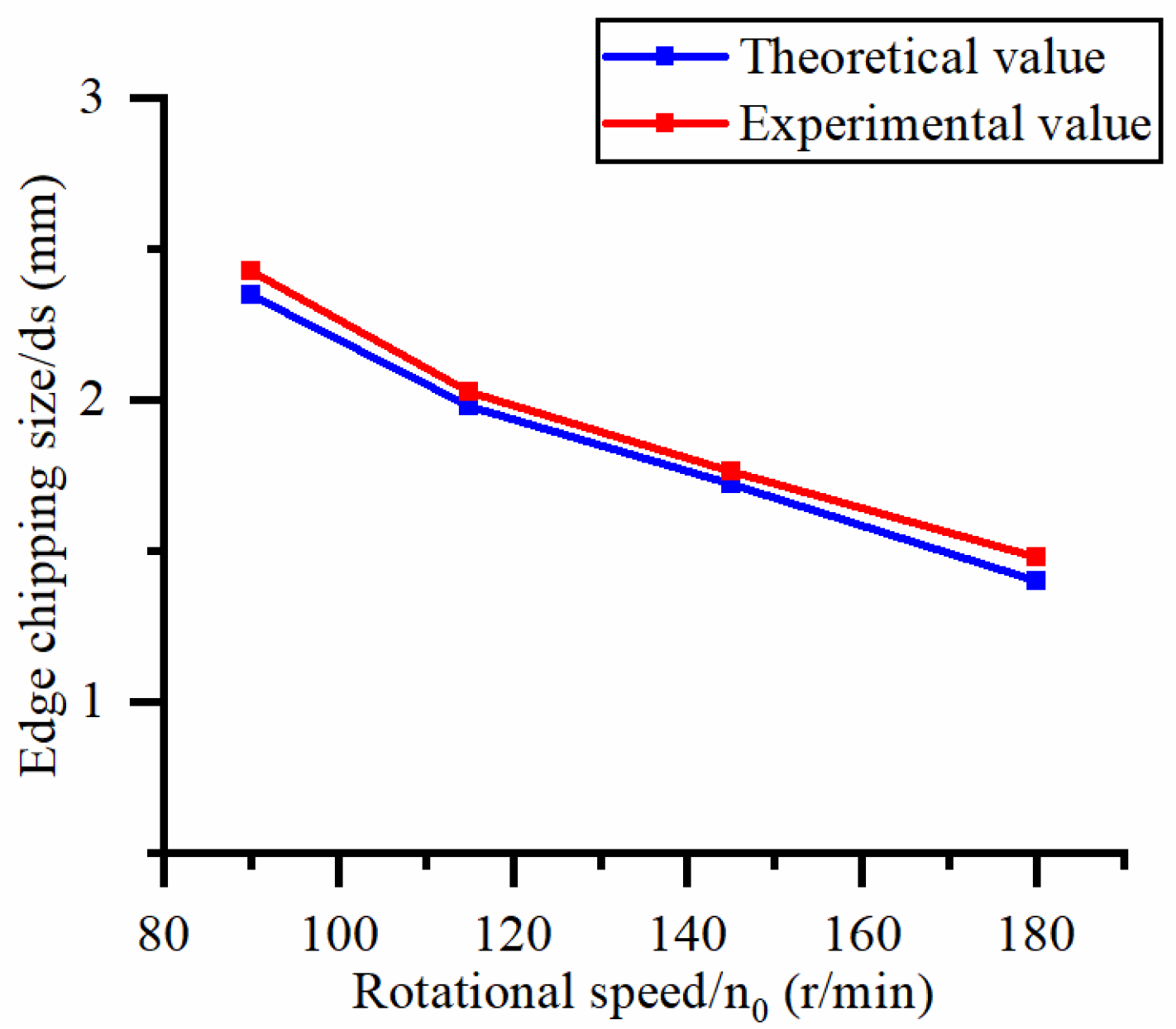
4.2. The Influence of Process Parameters on the Exit-Chipping Width
5. Conclusions
Author Contributions
Funding
Institutional Review Board Statement
Informed Consent Statement
Data Availability Statement
Acknowledgments
Conflicts of Interest
Nomenclature
| Cl | Lateral crack length (μm) |
| α | Dimensionless constant |
| φ | Half angle of the abrasive tip (°) |
| E | Elastic modulus of the material (GPa) |
| KIC | Fracture toughness of the material (MPa·m1/2) |
| Hv | Hardness of the material (GPa) |
| Fan | Axial force exerted on a single abrasive particle (N) |
| Fn | Axial force exerted on the cutter (N) |
| vf | Workpiece feed rate (μm/s) |
| n0 | Rotation speed of trepanning cutter (r/min) |
| D | Outer diameter of the trepanning cutter (mm) |
| d | Inner diameter of the trepanning cutter (mm) |
| m | Effective number of abrasive particles involved in machining |
| Rz | Maximum distance between the peak and valley depth on the micro profile of the measured workpiece surface (μm) |
| Sa | Surface roughness of the hole wall (μm) |
| Cm | Median crack depth generated by a single abrasive particle pressing into a brittle material (μm) |
| ε | Proportional constant independent of material properties |
| ds | Exit-chipping width (mm) |
References
- Esmaeilzare, A.; Rahimi, A.; Rezaei, S.M. Investigation of subsurface damages and surface roughness in grinding process of zerodur® glass–ceramic. Appl. Surf. Sci. 2014, 313, 67–75. [Google Scholar] [CrossRef]
- Chen, J.; Fang, Q.; Li, P. Effect of grinding wheel spindle vibration on surface roughness and subsurface damage in brittle material grinding. Int. J. Mach. Tools Manuf. 2015, 91, 12–23. [Google Scholar] [CrossRef]
- Ma, L.; Gong, Y.; Chen, X. Study on surface roughness model and surface forming mechanism of ceramics in quick point grinding. Int. J. Mach. Tools Manuf. 2014, 77, 82–92. [Google Scholar] [CrossRef]
- Li, C. Research progress of ductile removal mechanism for hard-brittle single crystal materials. J. Mech. Eng. 2019, 55, 181–190. [Google Scholar] [CrossRef]
- Sharma, A.; Babbar, A.; Jain, V.; Gupta, D. Influence of cutting force and drilling temperature on glass hole surface integrity during rotary ultrasonic drilling. In Advances in Production and Industrial Engineering; Springer: Berlin/Heidelberg, Germany, 2021; pp. 369–378. [Google Scholar] [CrossRef]
- Lv, D.; Liu, D.; Chen, G.; Song, L.; Yan, C.; Wu, X.; Zhu, Y. Formation mechanisms of exit-chippings in rotary ultrasonic drilling and conventional drilling of glass bk7. J. Manuf. Sci. Eng. 2020, 142, 4045416. [Google Scholar] [CrossRef]
- Lv, D.; Liu, D.; Chen, M.; Chen, G.; Yan, C.; Ali, I.; Zhu, Y. A mechanistic model for prediction of exit-chipping width in rotary ultrasonic drilling of sapphire. Int. J. Adv. Manuf. Technol. 2022, 120, 3519–3527. [Google Scholar] [CrossRef]
- Ding, K.; Fu, Y.; Su, H.; Chen, Y.; Yu, X.; Ding, G. Experimental studies on drilling tool load and machining quality of c/sic composites in rotary ultrasonic machining. J. Mater. Process Technol. 2014, 214, 2900–2907. [Google Scholar] [CrossRef]
- Zheng, L.; Wei, W.; Feng, Y.; Dong, X.; Zhang, C.; Zeng, Y.; Huan, H. Drilling machinability of engineering ceramics under low-frequency axial vibration processing by sintering/brazing composite diamond trepanning bit. Ceram. Int. 2019, 45, 11905–11911. [Google Scholar] [CrossRef]
- Gao, C.; Yuan, J. Efficient drilling of holes in Al2O3 armor ceramic using impregnated diamond bits. J. Mater. Process Technol. 2011, 211, 1719–1728. [Google Scholar] [CrossRef]
- Zheng, L.; Wang, B.; Feng, B.; Gao, C.; Yuan, J. Experimental study on trepanning drilling of the ceramic composite armor using a sintering diamond tool. Int. J. Adv. Manuf. Technol. 2011, 56, 421–427. [Google Scholar] [CrossRef]
- Li, Z.C.; Jiao, Y.; Deines, T.W.; Pei, Z.J.; Treadwell, C. Rotary ultrasonic machining of ceramic matrix composites: Feasibility study and designed experiments. Int. J. Mach. Tools Manuf. 2005, 45, 1402–1411. [Google Scholar] [CrossRef]
- Jiao, Y.; Liu, W.J.; Pei, Z.J.; Xin, X.J.; Treadwell, C. Study on edge chipping in rotary ultrasonic machining of ceramics: An integration of designed experiments and finite element method analysis. J. Manuf. Sci. Eng. 2005, 127, 752–758. [Google Scholar] [CrossRef]
- Abdelkawy, A.; Hossam, M.; El-Hofy, H. Experimental investigation of the cutting forces and edge chipping in ultrasonic-assisted drilling of soda glass. Int. J. Adv. Manuf. Technol. 2018, 100, 1433–1449. [Google Scholar] [CrossRef]
- Wang, J.; Feng, P.; Zhang, J.; Zhang, C.; Pei, Z. Modeling the dependency of edge chipping size on the material properties and cutting force for rotary ultrasonic drilling of brittle materials. Int. J. Mach. Tools Manuf. 2016, 101, 18–27. [Google Scholar] [CrossRef]
- Li, X.; Gao, Y.; Liu, R.; Zhou, W. Experiment and theoretical prediction for subsurface microcracks and damage depth of multi-crystalline silicon wafer in diamond wire sawing. Eng. Fract. Mech. 2022, 266, 108391. [Google Scholar] [CrossRef]
- Wang, P.; Ge, P.; Gao, Y.; Bi, W. Prediction of sawing force for single-crystal silicon carbide with fixed abrasive diamond wire saw. Mater. Sci. Semicond. Process 2017, 63, 25–32. [Google Scholar] [CrossRef]
- Yu, R.; Li, S.; Zou, Z.; Liang, L. Mathematical modeling and experimental study of cutting force for cutting hard and brittle materials in fixed abrasive trepanning drill. Micromachines 2023, 14, 1270. [Google Scholar] [CrossRef] [PubMed]


| S.No. | Topics | Year | Author (s) | Summary of Work | Output |
|---|---|---|---|---|---|
| 1 | RUM and CD experiments | 2014 | Ding et al. [8] | The effects of RUM and CD on axial force, torque, hole quality, and drilling surface roughness. | The surface roughness of drilling holes obtained using RUM is lower than CD |
| 2 | Constant feed rate drilling experiments | 2019 | Zheng et al. [9] | Constant feed rate drilling experiments on Al2O3 and SiC materials using a diamond drill | The changes in axial force and hole wall surface microstructure during the drilling process |
| 3 | Experiments on drilling Al2O3 armored ceramics | 2011 | Gao et al. [10] | The effects of axial force and rotational speed on drilling efficiency and hole quality | Increasing axial force and rotational speed can improve drilling efficiency, but excessive axial force and excessive rotational speed can also reduce drilling efficiency. |
| 4 | Experiments on drilling ceramic composite armor | 2012 | Zheng et al. [11] | The effects of process parameters such as rotational speed and axial force on machining efficiency and hole wall surface quality | Choosing reasonable process parameters can greatly improve drilling efficiency |
| 5 | Experiments on rotary ultrasonic constant feed rate drilling of hard and brittle materials | 2005 | Li et al. [12,13] | The effects of parameters such as spindle speed, feed rate, and ultrasonic power on cutting force and size of hole edge collapse after processing | Spindle speed and feed rate, as well as their interaction, have significant effects on hole quality. |
| 6 | Experiments on soda glass using a fixed diamond abrasive cutter | 2018 | Abdelkawy et al. [14] | The effects of cutter surface abrasive density, rotational speed, and workpiece feeding on axial force and hole edge collapse | Low rotational speed and high feed rate would reduce the width of hole edge collapse |
| 7 | Experiments on drilling optical glass | 2021 | Sharma et al. [5] | The effects of drilling force and cutting temperature on the surface integrity of holes by drilling optical glass | Reducing cutting force and drilling temperature can reduce the stress during drilling, thereby improving the surface integrity of the workpiece |
| 8 | Formation mechanism of exit-chipping | 2020 | Lv et al. [6] | The formation mechanism of exit-chipping during RUD and CD of BK7 glass from both theoretical and experimental perspectives | A quantitative relationship between instantaneous extrusion pressure and crack propagation direction that is inversely proportional |
| 9 | Establishment of the prediction model for the hole-chipping size | 2016 | Wang et al. [15] | The influence of cutting force and machining-induced subsurface crack damage on hole-chipping. | A prediction model for the hole-chipping size during rotary ultrasonic drilling of hard and brittle materials |
| Serial Number | 1 | 2 | 3 | 4 | 5 | 6 | 7 | 8 |
|---|---|---|---|---|---|---|---|---|
| Rotational speed n0/(r/min) | 90.5 | 90.5 | 90.5 | 90.5 | 90.5 | 113.5 | 144 | 181 |
| Feed rate vf/(μm/s) | 10 | 12 | 15 | 18 | 20 | 20 | 20 | 20 |
| Process Parameters | Surface Morphology | Surface Roughness |
|---|---|---|
| No. 1 n0 = 90.5 rpm vf = 10 μm/s |  |  |
| No. 2 n0 = 90.5 rpm vf = 12 μm/s |  | 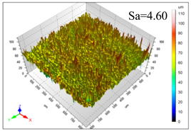 |
| No. 3 n0 = 90.5 rpm vf = 15 μm/s |  | 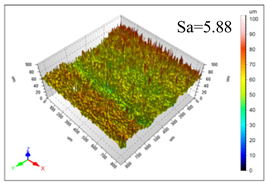 |
| No. 4 n0 = 90.5 rpm vf = 18 μm/s | 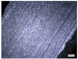 | 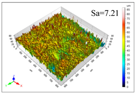 |
| No. 5 n0 = 90.5 rpm vf = 20 μm/s | 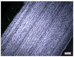 | 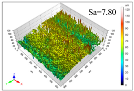 |
| No. 6 n0 = 113.5 rpm vf = 20 μm/s |  | 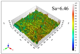 |
| No. 7 n0 = 144 rpm vf = 20 μm/s | 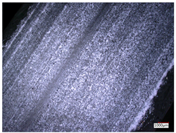 | 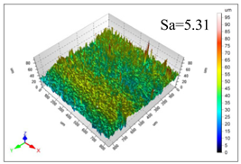 |
| No. 8 n0 = 181 rpm vf = 20 μm/s | 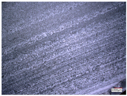 | 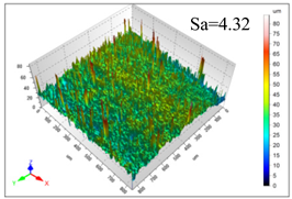 |
| Process parameters | No. 1 n0 = 90.5 rpm; vf = 10 μm/s ds = 1.14 | No. 2 n0 = 90.5 rpm; vf = 12 μm/s ds = 1.70 |
| Exit-chipping image | 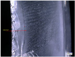 |  |
| Process parameters | No. 3 n0 = 90.5 rpm; vf = 15 μm/s ds = 1.79 | No. 4 n0 = 90.5 rpm; vf = 18 μm/s ds = 2.04 |
| Exit-chipping image | 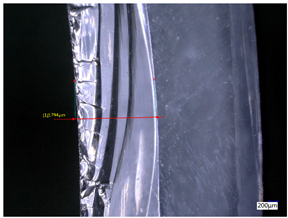 | 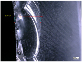 |
| Process parameters | No. 5 n0 = 90.5 rpm; vf = 20 μm/s ds = 2.43 | No. 6 n0 = 113.5 rpm; vf = 20 μm/s ds = 2.03 |
| Exit-chipping image |  | 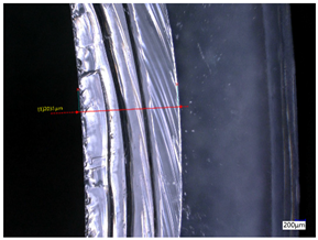 |
| Process parameters | No. 7 n0 = 144 rpm; vf = 20 μm/s ds = 1.76 | No. 8 n0 = 181 rpm; vf = 20 μm/s ds = 1.48 |
| Exit-chipping image | 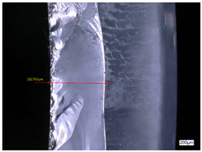 | 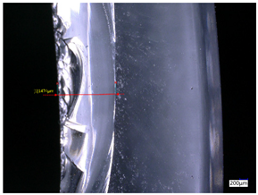 |
| Serial Number | Rotational Speed n0/(r/min) | Feed Rate vf/(μm/s) | Theoretical Values Sa/(μm) | Experimental Values Sa/(μm) | Error (%) |
|---|---|---|---|---|---|
| 1 | 90.5 | 10 | 5.14 | 4.03 | 27.43 |
| 2 | 90.5 | 12 | 5.76 | 4.60 | 25.11 |
| 3 | 90.5 | 15 | 6.62 | 5.88 | 12.52 |
| 4 | 90.5 | 18 | 7.41 | 7.21 | 2.84 |
| 5 | 90.5 | 20 | 7.91 | 7.80 | 1.53 |
| 6 | 113.5 | 20 | 6.82 | 6.46 | 5.55 |
| 7 | 144 | 20 | 5.90 | 5.31 | 11.08 |
| 8 | 181 | 20 | 5.15 | 4.32 | 19.28 |
| Serial Number | Rotational Speed n0/(r/min) | Feed Rate vf/(μm/s) | Theoretical Values ds/(mm) | Experimental Values ds/(mm) | Error (%) |
|---|---|---|---|---|---|
| 1 | 90.5 | 10 | 1.32 | 1.14 | 16.10 |
| 2 | 90.5 | 12 | 1.75 | 1.70 | 2.94 |
| 3 | 90.5 | 15 | 1.95 | 1.79 | 8.70 |
| 4 | 90.5 | 18 | 2.30 | 2.04 | 12.63 |
| 5 | 90.5 | 20 | 2.35 | 2.43 | −3.21 |
| 6 | 113.5 | 20 | 1.98 | 2.03 | −2.46 |
| 7 | 144 | 20 | 1.72 | 1.76 | −2.38 |
| 8 | 181 | 20 | 1.40 | 1.48 | −5.41 |
Disclaimer/Publisher’s Note: The statements, opinions and data contained in all publications are solely those of the individual author(s) and contributor(s) and not of MDPI and/or the editor(s). MDPI and/or the editor(s) disclaim responsibility for any injury to people or property resulting from any ideas, methods, instructions or products referred to in the content. |
© 2023 by the authors. Licensee MDPI, Basel, Switzerland. This article is an open access article distributed under the terms and conditions of the Creative Commons Attribution (CC BY) license (https://creativecommons.org/licenses/by/4.0/).
Share and Cite
Yu, R.; Li, S.; Zou, Z.; Liang, L.; Zhang, J. A Study on the Influence of Process Parameters on the Workpiece Surface Quality in the Cutting of Hard and Brittle Materials with Trepanning Drill. Materials 2023, 16, 6114. https://doi.org/10.3390/ma16186114
Yu R, Li S, Zou Z, Liang L, Zhang J. A Study on the Influence of Process Parameters on the Workpiece Surface Quality in the Cutting of Hard and Brittle Materials with Trepanning Drill. Materials. 2023; 16(18):6114. https://doi.org/10.3390/ma16186114
Chicago/Turabian StyleYu, Ruijiang, Shujuan Li, Zhengkang Zou, Lie Liang, and Jiawei Zhang. 2023. "A Study on the Influence of Process Parameters on the Workpiece Surface Quality in the Cutting of Hard and Brittle Materials with Trepanning Drill" Materials 16, no. 18: 6114. https://doi.org/10.3390/ma16186114
APA StyleYu, R., Li, S., Zou, Z., Liang, L., & Zhang, J. (2023). A Study on the Influence of Process Parameters on the Workpiece Surface Quality in the Cutting of Hard and Brittle Materials with Trepanning Drill. Materials, 16(18), 6114. https://doi.org/10.3390/ma16186114