Article

Thermodynamic and Ab Initio Design of Multicomponent Alloys Based on (Fe50Mn30Co10Cr10)-xBx (x = 0, 5, 7, 10, and 15 at.%)

by
Rodrigo Vargas-Osorio
1,
Laura Gabriela Torres-Mejia
2,
Lais Mujica-Roncery
2,
Jose Y. Aguilar-Hurtado
3 and
Katherine Paredes-Gil
1,4,*
1
Departamento de Química, Facultad de Ciencias Naturales, Matemática y del Medio Ambiente, Universidad Tecnológica Metropolitana, Santiago 7800003, Chile
2
Grupo de Investigación en Materiales Siderúrgicos e INCITEMA, Universidad Pedagógica y Tecnológica de Colombia, Tunja 150003, Boyacaá, Colombia
3
Departamento de Ingeniería Mecánica, Facultad de Ingeniería, Universidad Tecnológica Metropolitana, Santiago 7800003, Chile
4
Programa Institucional de Fomento a la Investigación, Desarrollo e Innovación, Universidad Tecnológica Metropolitana, Ignacio Valdivieso 2409, Santiago 8940577, Chile
*
Author to whom correspondence should be addressed.
Materials 2023, 16(16), 5579; https://doi.org/10.3390/ma16165579
Submission received: 1 July 2023 / Revised: 1 August 2023 / Accepted: 2 August 2023 / Published: 11 August 2023
(This article belongs to the Special Issue Compositional Complex Alloys: From Amorphous to High-Entropy)

Abstract

:
Multicomponent alloys have attained general interest in recent years due to their remarkable performance. Non-equiatomic alloys with boron addition as an interstitial element are being studied, exhibiting outstanding mechanical properties. In order to estimate the mechanical behavior of potential alloys, thermodynamic and ab initio calculations were utilized in this work to investigate phase stability and stacking fault energy (SFE) for (Fe50Mn30Co10Cr10)-xBx (x = 0, 5, 7, 10, and 15 at.%) systems. Thermodynamic experiments revealed two structural variations of borides, M2B(C16) with a tetragonal structure and M2B(CB) with an orthorhombic structure. Borides precipitate when boron content increases, and the FCC matrix becomes deficient in Mn and Cr. According to ab initio calculations, the presence of boron in the FCC and HCP structures primarily disrupts the surroundings of the Fe and Mn atoms, resulting in an increased distortion of the crystal lattice. This is related to the antiferromagnetic condition of the alloys. Furthermore, for alloys with a low boron concentration, the stacking fault energy was found to be near 20 mJ/m2 and greater than 50 mJ/m2 when 10 and 15 at.% boron was added. As boron concentrations increase, M2B borides are formed, generating changes in the matrix composition prone to fault-induced phase transitions that could modify and potentially impair mechanical properties.

1. Introduction

Multicomponent alloys between high-entropy alloys (HEAs) have attained a scientific interest over the last decade due to their remarkable properties, such as a high hardness, ductility, mechanical resistance, thermal stability, wear, and corrosion resistance, to name a few [1,2,3,4,5,6,7,8,9]. These are distinguished by a combination of at least five elements (metallic and non-metallic) with concentrations ranging from 5 to 35 at.%, forming solid solutions (SS) with crystalline structures such as BCC, FCC, and HCP, among others [9,10,11]. In this type of alloys, the effect of high entropy favors the stability of the solid-solution phases, decreasing the tendency for the formation of intermetallic phases, resulting in simpler microstructures with potential applications [12,13,14,15,16,17,18,19,20,21].
The alloy Fe20Mn20Co20Cr20Ni20, also known as the Cantor alloy, solidifies in a single FCC phase, demonstrating exceptional mechanical properties, strength, and ductility at the same time, showing a notable gap concerning conventional alloys, inclusive at cryogenic temperatures [22,23,24,25]. Currently, the study of HEAs has focused on the addition of non-equiatomic quantities of elements, as well as the incorporation of interstitial elements such as C, N, and B, considering that the hardening of the alloys is influenced by these components, in addition to the main elements that comprise the solid solution [26,27,28,29,30]. Chmielak et al. recently investigated the addition of C and in combination with N as interstitial elements in the CrMnFeCoNi alloy, focusing on its mechanical properties from 77 K to 673 K, microstructure, corrosion resistance, and wear resistance [27]. In comparison to the interstitial free FeMnCoCrNi reference alloy, the addition of C and N results in an increase in yield strength and ultimate tensile strength, and a decrease in the ductility. Additionally, all the systems exhibit a reduction in ductility, strength, and specific fracture energy as the temperature increases. Wear resistance at room temperature was lower than that of austenitic steels, whereas surface corrosion performance was comparable to that of reported austenitic steels [27]. In contrast to the previous results, other studies focused on the addition of small amounts of boron to the equiatomic and non-equiatomic FeMnCoCrNi Cantor alloy [28,29], finding that the material exhibits boron segregation, which has a direct effect on grain size and, as a result, stronger cohesion at the grain boundaries, without resulting in a reduction in ductility. In the multicomponent alloy Fe50-xMn30Co10CrBx (x = 0, 0.1, 0.66, and 5.4 at.%) [31,32], a dual FCC-HCP phase was obtained from an athermal martensitic transformation ( γ ε ) , accompanied by the orthorhombic phase type M2B(CB) (M = Cr, Fe). When boron was added, microhardness increased from 291 to 445 HV, as well as the wear resistance by nearly 30% above the free boron alloy. This result is attributed to the eutectic strengthening effect and grain refinement of borides, and probably to multiple deformation mechanisms such as martensitic-transformation-induced plasticity (TRIP), twinning-induced plasticity (TWIP), and a dislocation glide, primarily due to an increase in a metastable FCC with the boron addition [31,32].
Behind the mechanical properties of HEAs, austenitic steels, and other FCC engineering materials is the stacking fault energy (SFE). The SFE is a physical property that governs the activation of different deformation mechanisms, mechanical behavior, and the phase transformation of crystalline alloys. SFE represents the energy associated with the tendency to alter the typical stacking fault sequence and build a distinctive type of defects (for example, the dissociation of partial Shockley dislocations), related to the dislocation movement and plastic deformation of metallic materials. In FCC metals, SFE is determined with the dissociation distance of partial dislocation in the {111} <110> slip system, and the modification in the stacking sequence results in a local stacking fault structure such as hexagonal-close-packed (HCP) nuclei. When SFE values are below 40 mJ/m2, it is commonly considered that martensitic-transformation-induced plasticity (TRIP) and deformation twinning are dominant, whereas a dislocation glide is typically present in materials with a high SFE [33]. As a result, SFE estimation is a powerful parameter for predicting and studying the mechanical behavior of multicomponent alloys.
The theoretical prediction as well as the experimental estimation of the SFE is not straightforward. Transmission electron microscopy (TEM) and X-ray diffraction (XRD) are utilized to determine the SFE by measuring the spacing between dissociated partial dislocations or obtaining the stacking fault probability from the mean square micro-strain ε2, respectively [34,35,36,37]. Thermodynamic calculations have been used to estimate SFE for various alloys using the Olson and Cohen equilibrium thermodynamic formalism [38,39,40]. Ab initio calculations using solid solution modelling at T = 0 K have also been used to determine SFE, allowing the atomistic comprehension of the mechanical behavior [41,42,43,44,45,46,47,48,49]. For example, combining experimental and theoretical calculations, the mechanical properties and SFE of the Cantor alloy and four non-equiatomic derivatives were examined, yielding values in the range of 30 ± 5 mJ/m2 [50]. Fe40-xMn20Co20Cr20Nix (x = 0–20 at.%) HEAs were recently studied using an ab initio design in relation to the HCP-FCC energy differences (ΔEHCP-FCC). The results revealed a substantial relationship between the HCP-FCC phase stability and Ni content, implying that the Fe34Mn20Co20Cr20Ni6 HEA had the highest strength [51,52]. Based on the foregoing, it is possible to study and predict the mechanical behavior using the SFE, integrating structural and thermodynamic characteristics, which provide a more complete understanding of the materials and, as a result, facilitate the design of promising alloys in studies related to the optimization of properties such as ductility, malleability, and hardness [42,43,49,51,52,53,54,55,56,57,58,59].
In this work, a thermodynamic and ab initio alloy design is proposed, based on the system Fe-Mn-Co-Cr with the addition of B as an interstitial element in 0, 5, 7, 10, and 15 at.%, with the aim of comparing and predicting the microstructural results of the Fe-Mn-Co-Cr alloy with a low boron content (0 and 5 at.%), and providing an insight on the structural features and mechanical behavior when 7, 10, and 15 at.% of boron is added. Empiric phase rules, phase diagrams, thermodynamic stability, and stacking fault energy make up part of this study. The final objective was to understand how the boron addition affects the relationship of structure–mechanical properties. In this context, the design of HEAs with boron addition is a promising concept that provides a solution to the abrasive wear of equipment and deterioration problems in surface engineering uses [60,61].

2. Materials and Methods

2.1. Phase Prediction with Empiric Parameters

The concentration of the components, along with specific physicochemical factors, are critical in the investigation of HEA formation. Parameters such as the entropy and enthalpy of mixing, as well as lattice distortion, are studied for a better understanding and prediction of their behavior [62,63].
According to Ludwig Boltzmann, who defined the configurational entropy, the more components there are, the more alternative configurations exist, and hence the entropy increases. Thus, for a random n-component solid solution, the ideal configurational entropy per mole is given by the following [54]:
S = R i = 1 n C i l n C i
where R represents the gas constant ( 8.314   J / mol   K ), C i corresponds to the atomic percentage of component i , and n is the number of alloy components.
The enthalpy of mixing is the amount of energy that a system exchanges with its surroundings, and is expressed as
H = i = 1 ,   j 1 n Ω i j C i C j
where Ω i j is the mixing enthalpy of binary alloys, with C i and C j as the mole fractions of components i and j , respectively [54]. The enthalpy of mixing defines the distribution of atoms in the solid solution (SS), which is grouped if H m i x > 0 or dispersed if H m i x < 0 [9].
The previous parameters can be employed in the variable Ω that relates the effects of the enthalpy and entropy of mixing to predict the formation of a solid solution phase and is expressed as
Ω = T m S m i x | H m i x |
  T m = i = 1 n C i ( T m ) i
where T m corresponds to the average melting temperature of the set of alloy components; likewise, ( T m ) i denotes the inherent melting point of each component [64,65].
Similar electro-negativities of the solute and solvent are associated with the formation of solid solutions. Nevertheless, a significant difference indicates a tendency for the formation of intermetallic phases. This difference is known as
χ = i = 1 n C i ( X i X a v ) 2
where n is the number of elements, C i and X i are the composition, and the Pauling electronegativity of the alloy is expressed as X a v [64].
The solute–solvent atomic size difference is a crucial factor in predicting solid solution formation in HEA. A difference of less than 15% indicates its formation. This difference is denoted as follows:
δ = i = 1 n C i ( 1 r i r ¯ ) 2
r ¯ = i = 1 n C i r i
where r ¯ is the average of the atomic radii of the elements of the system, r i is the atomic radius of the element i , and C i is the atomic percentage of the element i in the HEA.
HEAPS software V1.0 (High Entropy Alloy Prediction Software) was used to determine these parameters [66]. The parameters were classified into various criteria, which are listed in Table 1.

2.2. Thermodynamic CALPHAD Calculations: Phase Diagram Prediction

The CALculation of PHAse Diagrams (CALPHAD) approach was used in conjunction with Thermo-Calc software version 2023 and the TCEF9 database. For the (Fe50Mn30Cr10Co10)-xBx system, equilibrium calculations were carried out to estimate the phase diagram as well as the molar fraction of stable phases as a function of temperature and molar fraction of elements in phases as a function of temperature.
The Olson–Cohen model for the intrinsic SFE in FCC metals and alloys was used to estimate the stacking fault energy from a thermodynamic approach [39], complemented by the model proposed by Hirth, where a stacking fault in an FCC crystal structure consists of a thin-layer HCP phase [67]. The most significant contribution is the difference in Gibbs free energy ( G C γ ε )   between the ε-HCP and γ-FCC phases. As a result, the SFE (γisf, mJ/m2) can be expressed as follows:
S F E   ( γ i s f ) = 2 . 4 3 . a 2 . N A .   G C γ ε + 2 . σ γ ε
where G C γ ε   is the molar Gibbs energy difference in the phase transformation between the austenite   γ and the ε -martensite. At 298.15 K and 1 bar, metastable phase calculations in terms of Gibbs free energy as a function of the composition were performed using Thermo-Calc software and the TCFE9 database, considering the matrix composition from the equilibrium calculations (affected by boride formation), suspending all phases except for FCC and HCP. The interfacial energy, which ranges from 0 to 10 mJ/m2, is denoted with the term   σ γ / ε . Based on data provided for a comparable, an average value of 8 mJ/m2 was assumed [37,68,69]. The expression 4 3 . a 2 . N A describes the molar surface density along { 1   1   1   }   planes, where a is the lattice parameter of the alloys specified in references [32].   N A is Avogadro’s number, and the integer value 2 denotes the number of densely packed planes in the HCP ε -martensite phase.

2.3. Ab Initio DFT Solid Solution Modelling

Solid solution modelling was applied to obtain a random structure with the optimal chemical disorder arrangement [43]. This was performed using the special quasi-random structures (SQS) methodology [70,71,72,73,74,75] implemented in an alloy theoretic automated toolkit (ATAT) program [76]. An objective function was minimized, taking into account (i) a supercell size of 60 atoms, (ii) a chemical composition of (Fe50Mn30Cr10Co10)-xBx (x = 0, 5, 7, 10, and 15 at.% associated with alloy-B0, alloy-B5, alloy-B7, alloy-B10, and alloy-B15, respectively), and (iii) a third nearest-neighbor distance for FCC and HCP structures ranging from 3.0 to 6.0 Å. Afterwards, 1 and 2 boron atoms were added as interstitial atoms in octahedral sites into Fe30Mn18Co6Co6 and Fe27Mn15Co9Cr9 alloys, according to the heat of mixing reported for the metal-boron binary [77]. It should be noted that the compositions of the studied alloys, (Fe50Mn30Cr10Co10)-xBx (x = 0, 5, 7, 10, and 15 at.%), will be addressed considering the metal alloy as 100, 95, 93, 90, and 85% of the solid solution, respectively. When the boron level exceeded 10 at.%, the Fe, Mn, Co, and Cr amounts fluctuated dramatically. Solid solution structures for the intermetallic compounds (Cr, Fe)2B (M2BCB) and (Fe,Cr)2B (M2BC16) with an orthorhombic and tetragonal crystalline structure, respectively, were also obtained to complement the discussion. All the exact compositions are listed in Table 2:
A Vienna Ab-initio Simulation Package (VASP, version 6.2) [78,79] was used to perform DFT periodic calculations with the Perdew–Burke–Ernzerhof (PBE) exchange–correlation functional, which has been widely reported for extended systems [80,81,82]. The valence electrons are extended in a plane waves basis set for each metal, and the core electrons are characterized by the projector augmented wave (PAW) pseudopotential. For the (5 5 5) K-point mesh, the Monkhorst–Pack sampling of the Brillouin zone was used. This mesh was chosen based on the optimal trade-off between the accuracy and the computational cost that had previously been evaluated [83]. ISIF = 3 was used to maximize all FCC and HCP supercells, cell shape, and cell volume. The plane waves’ energy cut-off was set to 500 eV, the self-consistent field (SCF) tolerance was 1 × 10⁻⁶ eV, and the geometry relaxation was considered as convergent when the energy difference from the previous optimization step was less than 1 × 10⁻⁵ eV. To account for the magnetic properties of the studied alloys, the co-linear spin correction energy (ISPIN = 2) was included in the optimized geometry. For each atom, we specified the initial magnetic moment: Fe (S = 1), Mn (S = −1.5), Co (S = 1.5), and Cr (S = 3) for a “ferromagnetic” state (FM) and Fe (S = −1), Mn (S = −1.5), Co (S = −1.5), and Cr (S = −3) for an antiferromagnetic state (AFM). Furthermore, a spin state (AFM-FM = PM) was evaluated, considering half of the moments as up and the other moments as down.
To investigate the phase stability and solubility of boron in the alloys, the formation enthalpy ( Δ H f )   [9,10] was calculated using the total energy of the optimal alloy supercell and the weighted energies of each element in their most stable magnetic state as follows:
H f ( A m , B n , C o , D p , E q ) = E ( A m , B n , C o , D p , E q ) 1 m + n + o + p + q ( mE ( A ) + nE ( B ) + oE ( C ) + pE ( D ) + qE ( E ) )
The SFE was obtained using Stocks et al.’s [48,84] axial interaction model. Based on this approach, the SFE for the martensitic transformation can be estimated by taking into account the interactions of the (111) layer up to the nearest neighbor (ANNI model), which is defined in terms of the total energy of FCC and HCP structures, as well as the area of the (111) plane (A). Thus, the SFE can be expressed as
S F E A N N I   = E h c p E f c c A
The SFE for the phase transformation between the intermetallic compounds (Cr, Fe)2B and (Fe,Cr)2B was computed using this definition, considering the total energy of orthorhombic and tetragonal structures, as well as the area of the (001) plane (A) in relation to that reported by Goldfarb and co-workers [85]. Finally, it is important to note that this equation predicts the SFE exclusively through ab initio calculations, enabling the rationalization of strain-hardening behavior based on the structural and physicochemical properties.

3. Results

3.1. Empiric Formation Phase Rule Analysis

The enthalpy of mixing, entropy of mixing, valence electron concentration, electronegativity, distortion parameter, ratio of entropy/enthalpy contribution, and melting temperature of the alloys (Fe50Mn30Cr10Co10)-xBx (x = 0, 5, 7, 10, and 15 at.%) were determined (see Section 2.2). Table 3 shows that the distortion parameter (δr) ranges between 3.83 and 13.96%, which can be connected with the formation of stable solid solutions, because it has been reported that multiphase/intermetallic HEA takes place when 1 ≤ δr ≤ 13.5%. Furthermore, the electronegativities are similar, which support the solid solution formation. Additionally, the enthalpy of mixing revealed a random distribution of atoms since H m i x < 0 . These parameters increase as the boron content increases, indicating that this element forms part of the solid solution as an interstitial atom. VEC parameter values are in the same range as those published for Fe50Mn30Co10Cr10Bx (x = 0, 0.1, 0.66, and 5.4 at.%) [32]. These values are solely applied to the boron-free alloy, which exhibited both FCC and BCC phases, because it has been shown that both FCC and BCC phases are stable at 6.78 ≤ VEC ≤ 8.0.
Table 4 describes the criteria for the formation phase of alloy-B0 through alloy-B5 in HEAPS software. Based on the MC1 formation criteria, it is possible to observe that raising the boron level from 5 to 10 at.% can result in the formation of either an intermetallic compound (IM) or a bulk metallic glass (MBG). Similar results were found using the MC2 criterion, which compared the parameter Ω (which relates both ∆S and Tm in relation to ∆H) with the variable δr. Therefore, the findings are consistent with previous research that discovered the formation of compounds such as iron and chromium borides (M2B) [32,86].
The MC7 criterion suggested that an intermetallic phase would form without and with the boron addition. However, it is not impossible because the mixing enthalpy is negative, indicating the formation of stable solution solids, thus being a mistake in the HEAPS software criterion. Moreover, for alloy-B0 (Fe50Mn30Co10Cr10), the phases BCC, FCC, and HCP in solid solutions were determined experimentally, confirming the error mistake in this criterion [32]. The MC7 criterion solely examines the relationship of T over Tm-δr-∆Hmix, and does not include the ∆S of the mixture. This variable is particularly relevant since boron interacts differently in the system depending on the elements with which it is coordinated, affecting the microstates that comprise the overall system state. Finally, the IMF1 criterion evaluated using ∆XP suggests the formation of topologically compact phases (TCP), which is attributed to an unusually robust structural state, which would be interesting to explore in future investigations.

3.2. Phase Diagram Prediction for (Fe50Mn30Cr10Co10)-xBx (x = 0, 5, 7, 10, and 15 at.%)

The pseudobinary phase diagram was calculated as a function of the boron content (at.%) (Figure 1), under thermodynamic equilibrium conditions. According to the isoplethal section, a stable fcc austenitic structure and M2B borides (M denotes transitional metals) are formed from the liquid phase to 1200 °C until solidification. Besides the austenitic matrix, two structural variants of M2B-type borides can be present in the microstructure, M2B(C16) having a body-centered tetragonal structure (Strukturbericht notation, C16; space group, I4/mcm) and M2B(CB) with a face-centered orthorhombic structure (Strukturbericht notation, Cb; space group, Fddd). M2B(CB) borides are found as a primary phase at boron contents lower than 15 at.%; meanwhile, M2B(C16) boride precipitates when the boron content is larger than 15 at.%, as a solid-state transformation under thermodynamic equilibrium conditions. Thus, one of the most important features of the phase diagram is the change in crystalline structure of the M2B borides from orthorhombic to tetragonal as the content of the interstitial element increases from 15 to 20 at.%. At temperatures below 600 °C, the austenitic matrix could decompose to a bcc ferritic matrix and intermetallic sigma phase.
Figure 2 illustrates a one-axis calculation of the molar fraction of stable phases for (Fe50Mn30Cr10Co10)-xBx (x = 0, 5, 7, 10, 15, and 20 at.%) as a function of temperature. At a boron content of 0 at.%, an FCC austenitic phase begins to form at a temperature of around 1300 °C. Additionally, at low temperatures, the sigma and BCC phases can occur. In the case of alloy-B0 fabricated with laser cladding, FCC and BCC were formed under conditions out of the thermodynamic equilibrium [32]. Nevertheless, the temperature–time process conditions, especially the cooling rate, are what determine whether the BCC phase is present or not. If the boron content increases, there is a significant decrease in the FCC phase. For boron contents of 5, 7, and 10 at.%, an increase in M2B(CB) is generated with FCC/boride ratios of 0.9/0.1, 0.8/0.2, and 0.7/0.3, respectively. Furthermore, the existence of M2B(C16) borides was undeniably present for boron contents of 15 and 20 at.%. Thus, it can be seen that the ratio of M2B(CB)/M2B(C16) is 0.6/0.4 when the boron content is 15 at.% and 0.3/0.7 when the boron content is 20 at.%. Therefore, the amount of tetragonal boride increases when the boron content is increased from 15 to 20 at.%, while the orthorhombic boride decreases and the FCC phase gradually disappears, which is related to the phase transformation into the two types of M2B borides.
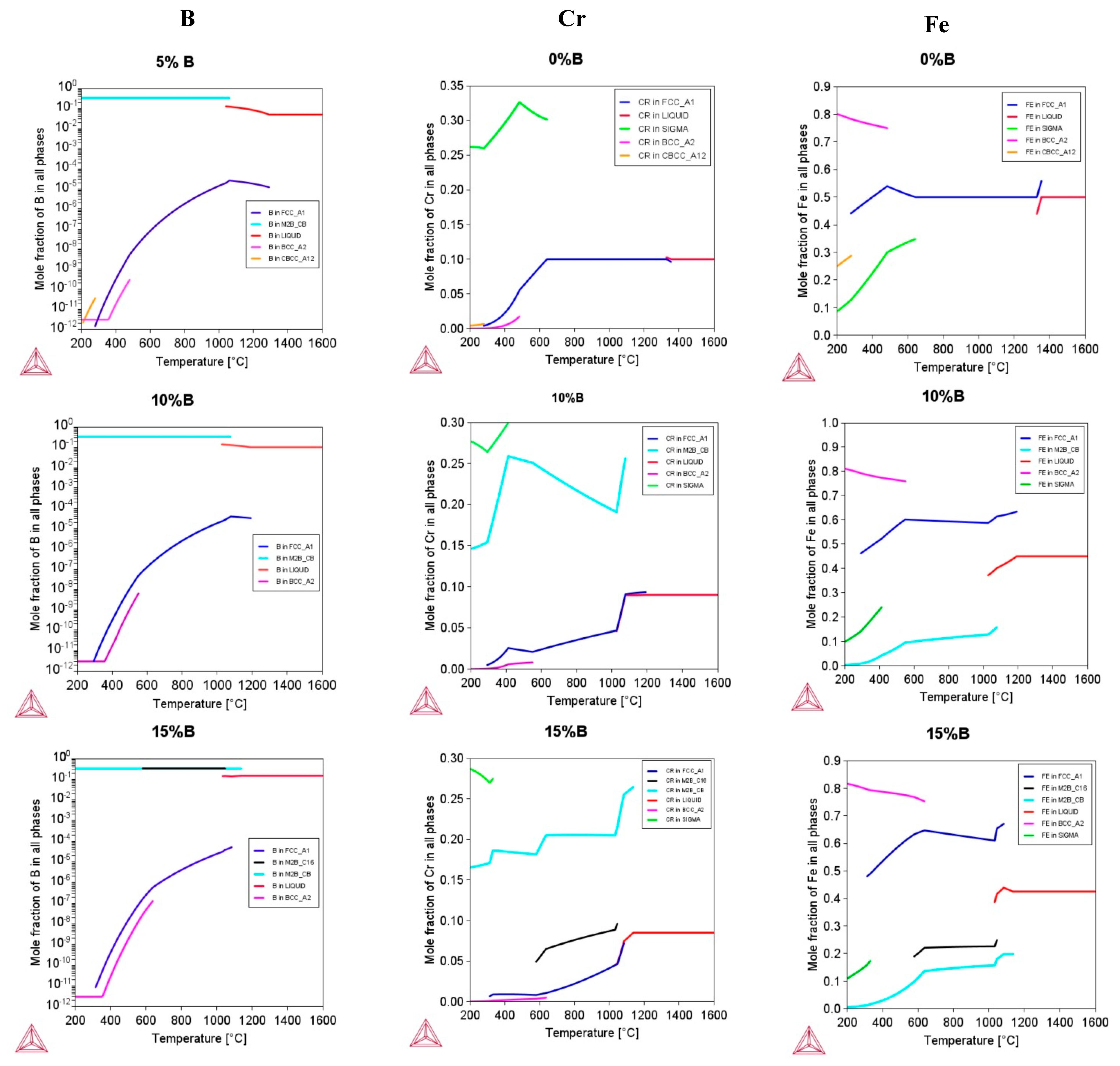
Figure 3 shows the Cr, Fe, and B distribution in the phases with varying boron contents. For the boron-free system, it can be seen that Cr is mainly distributed in the FCC phase, while with the addition of boron, the FCC matrix is depleted, and a greater proportion of Cr is found in borides, mainly in M2B(CB). This indicates that the formation of Cr-rich borides is possible, as was also observed in similar alloys produced with arc-melting and laser cladding [31,32]. Fe is mainly distributed in the FCC phase for the free boron system. Thus, small amounts of iron are present in the M2B(CB) boride when the boron content increases. It is noted that Fe can be found in borides with a larger B addition (15 at.%), in this case, mostly in the M2B(C16) type. Interestingly, these changes were observed in boron-doped alloys [86].
Finally, at a boron percentage of 5 at.%, it is noticed the M2B(CB) boride predominantly contains the greatest amount of boron, whereas the FCC matrix decreases significatively in the boron content. Thus, as the boron percentage increases to between 10 and 15 at.%, the presence of borides becomes more stable, and the matrix retains a low boron content.
Regarding non-equilibrium calculations on the stability of the FCC structure in relation to the deformation mechanisms and mechanical properties, SFE values were obtained with the CALPHAD method, as are shown in Table 5. An increase in boron content modifies the Gibbs free energy of the FCC and HCP lattice; in all cases, the energy associated with the FCC phase has lower values, indicating that it is more stable than the HCP phase. SFE increases with boron addition. For alloy-B0 and alloy-B5, the values are in the range of others reported [50]. Nevertheless, a significant variation of approximately 20 mJ/m2 is observed for the alloy containing 7 at.% boron, whereas the variation of the SFE is approximately 4 mJ/m2 for higher boron contents. This suggests a substantial change in the deformation mechanisms and in the mechanical properties of the alloy with a 7 at.% boron content.

3.3. Structure, Stability, Magnetic Role, and SFE for the Design Alloys (Fe50Mn30Cr10Co10)-xBx (x = 0, 5, 7, 10, and 15 at.%)

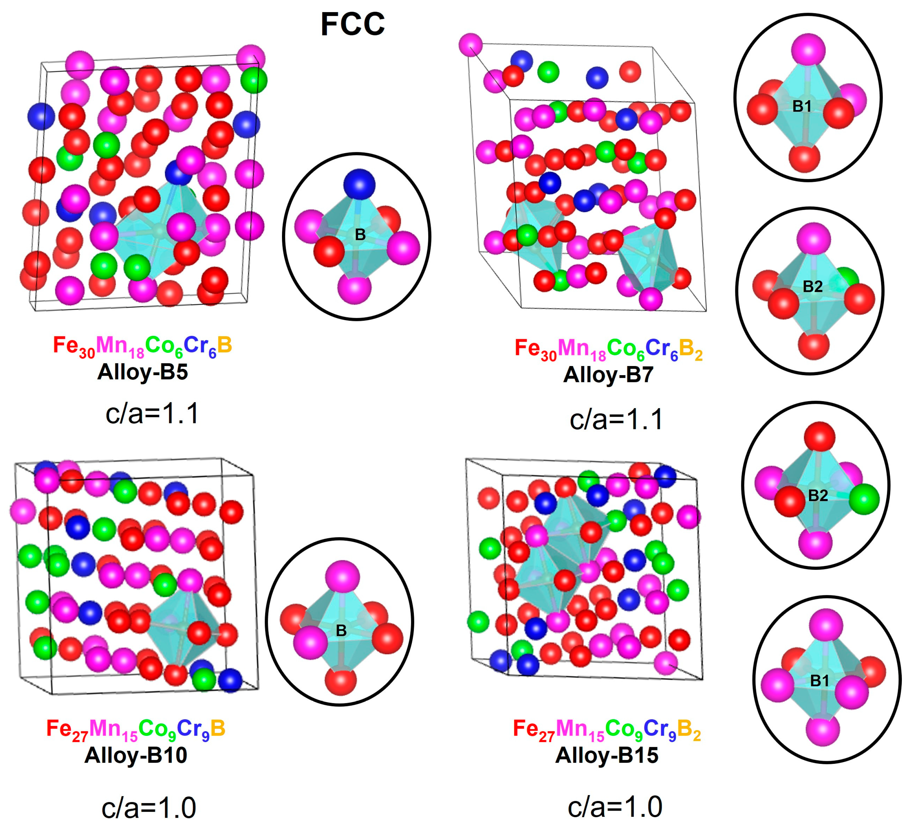
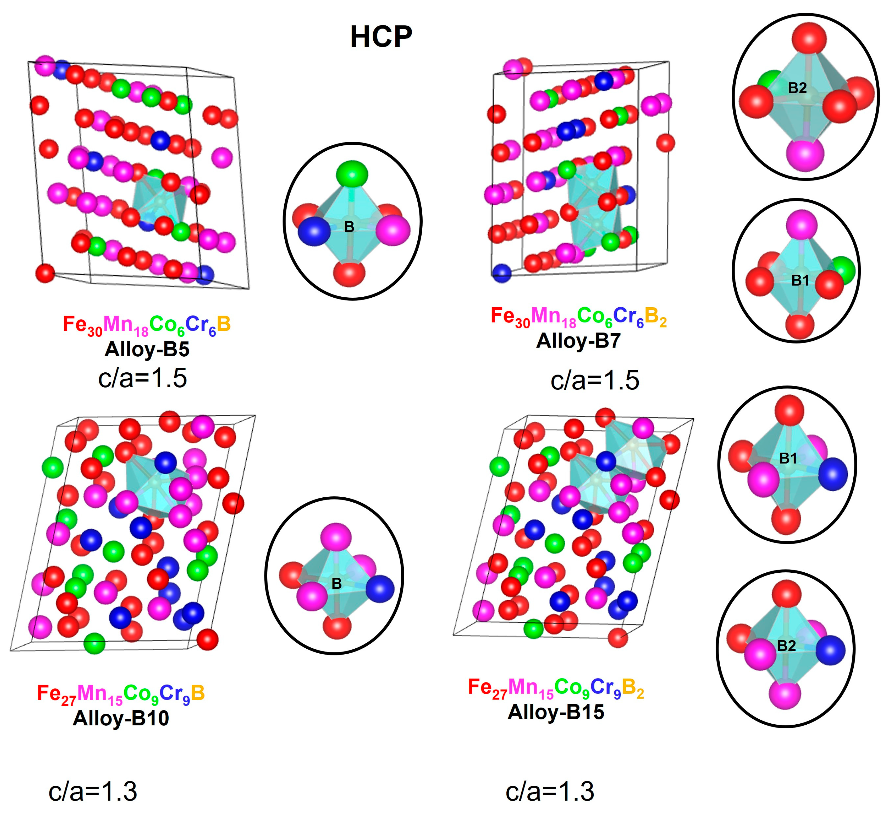
Figure 4 and Figure 5 depict the 60-atom optimized supercells for the FCC and HCP crystalline structures of the alloys (Fe50Mn30Cr10Co10)-xBx (x = 0, 5, 7, 10, and 15 at.%). The lattice parameters are closest to a perfect FCC and HCP structure with slight distortions characteristic of HEAs. In FCC, alloy-B5 and alloy-B10 are more ordered systems than alloy-B7 and alloy-B15, indicating that the larger boron addition in the supercell may affect the entropy of the systems. In FCC and HCP, the lattice parameters of alloy-B10 and alloy-B15 decrease slightly, which is associated with a lower Fe and Mn content compared to alloy-B5 and alloy-B7.
According to the mixing enthalpies reported for binary metal-boron systems (∆ Hmix M-B = −32 (MnB), −31 (CrB), −26 (FeB), and −24 (CoB) kJ/mol), manganese has the strongest affinity for boron, followed by chromium, iron, and cobalt [77]. For the FCC and HCP structures, it can be clearly observed that the boron prefers to form octahedral interactions with manganese and iron elements. Therefore, these atoms play a stabilizing role in the formation of alloys of this type.
Moreover, the prediction of the martensitic transformation γ ε was considered. In this regard, the principal diagonal of the FCC structures was compared to the c-parameter of HCP. The FCC principal diagonal in Fe30Mn18Co6Cr6B is 11.78 Å, while the c-parameter of HCP is 10.77 Å. Similar outcomes were observed for all the alloys modeled with the principal diagonal between 11.78 and 12.66 Å and the c-parameter between 10.48 and 10.77 Å. Consequently, the models applied in this work are structurally appropriate for analyzing martensitic transformations.
In order to compare the atomic distortions in the crystal lattice caused by the addition of boron, the root mean square deviation (RMSD) was calculated. According to Table 6, the average distortion of all elements in FCC phase lattice structures is greater than in HCP (alloy-B5 versus alloy-B7 and alloy-B10 versus alloy-B15). This result is attributed to the fact that the atoms of the FCC phase structures tend to deform into HCP phase structures. In terms of distortions per atom, the Cr and Co atoms are the most distorted in the FCC structures, while the Mn and Fe atoms are the most distorted in the HCP structures. Therefore, the results of the lattice distortions indicate that when boron is added, a greater distortion is generated, stabilizing interactions that could contribute to reducing the Gibbs free energy and achieving a solid solution with a low Gibbs free energy.
The values listed in Table 7 were examined in order to comprehend the stability of the alloys. The HCP phase was found to be more stable than the FCC phase in alloy-B0, alloy-B5, and alloy-B7, which is consistent with experimental studies of the Fe50-xMn30Cr10Co10Bx (x = 0 and 5 at.%). This study revealed that the predominant relative HCP phase composition was 85 and 64 at.% for the addition of 0 and 5 at.% of boron, respectively [32]. Moreover, the phase energy difference (ΔEHCP-FCC) indicates that 5.75 eV and 7.11 eV are required when 5 and 7 at.% boron is added, respectively. On the other hand, the energy values for alloy-B10 and -B15 had an opposite trend, indicating that the FCC phase is more stable than the HCP phase.
This conclusion is consistent with the SFE results obtained using the CALPHAD approach, which shows that the SFE rises due to the increased stability of the FCC phase against the HCP transformation. Thus, boride formation causes a significant alteration in the behavior of the FCC solid solution of alloys with a high boron content.
The enthalpy of formation for each alloy was estimated (Table 8). The values are most closely related to −14.0 kJ/mol. These results show that non-equiatomic alloys with boron additions are 6.0 kJ/mol more stable than the Fe20Mn20Cr20Co20Ni20 Cantor alloy (−8.43 kJ/mol) [50]. A similar tendency for total energy was found. The enthalpy of formation for HCP structures is lower for alloy-B0 and -B5, while it is higher for alloy-B7 to alloy-B15. Again, this suggests that when the boron content is high, the alloys exhibit a different physicochemical behavior. To scrutinize this topic, the enthalpy of formation for the intermetallic compounds, (Cr, Fe)2B and (Fe,Cr)2B, was calculated to be −23.0 and −23.7 kJ/mol, respectively. These values are considerably greater than the enthalpy of formation of the solid solution, which favors the formation of intermetallic compounds.
The magnetic corrections to the energy were calculated using spin-polarized calculations with an initial specified magnetic moment for each atom (Table 7). At T = 0 K, the alloys exhibited a “ferromagnetic” state. In this state, Cr, Fe, and Co have parallel spin states whereas Mn is exclusively antiparallel. As has been widely explicated, the Mn content plays a critical role in t magnetic stabilization [87,88]. Moreover, it is important to highlight that the boron addition can also be responsible for the magnetic behavior because a paramagnetic state has been reported for similar alloys to the CrMnFeCoNi Cantor alloy at room temperature [89]. Therefore, the boron addition favors a magnetic transformation at T = 0 K.
Table 9 shows the SFEs generated from the axial interaction model represented in Equation (10). The values for alloy-B0 to alloy-B7 range from 18.34 to 23.0 mJ/m2—consistent with the Cantor alloy (17–25 mJ/m2) [50]. The results showed that the SFEs increased as the B content increased by 7 at.%, implying that the presence of B generated a hardness that promoted the dissociation or segregation via twinning-induced plasticity (TWIP) and dislocation slip deformation mechanisms, affecting the SFE. These deformation mechanisms have an origin in the Fe-B and Mn-B short-range order interactions represented in an FCC solid solution’s octahedral cavity. Nevertheless, when the boron addition is greater than 10 at.%, the SFE decreases significantly. Therefore, it is suggested that the martensitic transformation is hindered due to the impoverishment of Cr and Fe atoms from the matrix in terms of participating in the formation of the M2B(CB) borides, which could be responsible for the lower SFE.
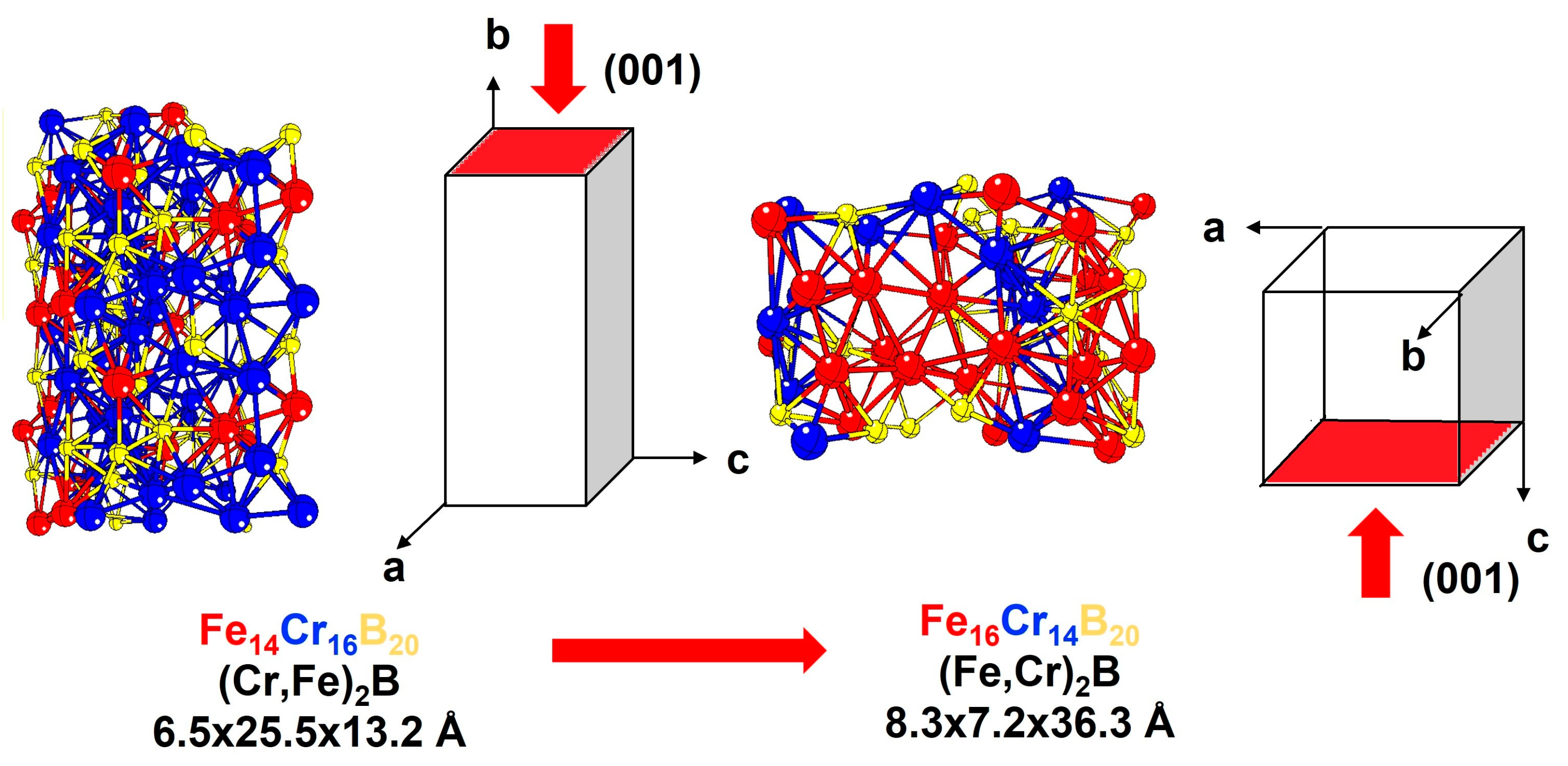
These SFE results are corroborated with the CALPHAD calculations, which indicate that the fcc matrix coexists with M2B(CB) and M2B(C16) borides in alloy-B10 and alloy-B15, respectively. These boride types have been experimentally identified with XRD [32] and HR-TEM [86], suggesting that M2B(CB) is a (Cr,Fe)2B that begins to transform into (Fe,Cr)2B if the Cr content exceeds the solubility limit. This transformation is a “fault-induced phase transformation” [85,90,91]. In this direction, we build and optimize, with SQS + DFT, a model for the orthorhombic (Cr,Fe)2B and tetragonal (Fe,Cr)2B (Figure 6). The phase energy difference (ΔEORT-TETRA) was determined to be 14.35 eV. Additionally, the SFE measured at 46.37 mJ/m2. For alloy-B10 and alloy-B15, it is suggested that the SFE should be the sum of the SFE resulting from the martensitic transformation (SFEANNI) and the SFE resulting from the boride phase transformation (SFEM2B).

4. Discussion

The thermodynamic parameters, CALPHAD method, and SQS + DTF calculations allowed for estimating the phase prediction and SFE results of the multicomponent (Fe50Mn30Co10Cr10)-xBx (x = 0, 5, 7, 10, 15, and 20 at.%) system alloy. Boron has an evident influence on the physical and chemical parameters of the HEAs proposed. Multiple phases are expected based on thermodynamic prediction when boron is added to this alloy. It is essential to highlight that a single phase is stable at high temperatures in the boron-free alloy. At higher concentrations of this interstitial element, borides form and the fcc matrix is depleted in Cr and Mn, which contributes to the stabilization of borides as an equilibrium phase transformation.
On the other hand, the hcp phase is not enclosed in the equilibrium calculations (Figure 1, Figure 2 and Figure 3), due to the fact that it is related to a non-equilibrium phase transformation caused by the high cooling rate during the solidification process in metastable conditions. The free Gibbs energy difference of the FCC (γ) and HCP (ε) phases with respect to the martensitic transition γ-ε is directly connected to the tendency to produce the HCP phase (Table 5). The larger the Δ G γ ε , the less likely an ε- or α-martensitic structure will be formed during the deformation of the thermal shock.
Considering the empiric formation phase rule analysis utilizing HEAPS, the best-fit phase prediction criteria are MC1, MC2, MC7, and IMF1. Experimentally, a dual phase (FCC + HCP) was obtained for this boron-free alloy, where HCP is caused by both a thermal martensitic-like partial-transformation-induced FCC phase and a high cooling rate [28,31,32]. For the IMF1 and VEC conditions, these characteristics would fit the sigma phase illustrated in Figure 3, which is often Cr-and-Mn-rich [83] but has not been observed experimentally because it is driven by diffusion processes that require extended heat treatments.
It is well known that the phase stability is determined with the competition between ΔH and TΔS, minimizing the Gibbs free energy. Nevertheless, as demonstrated for this system, a multicomponent alloy with distinct phases can be formed based on the boron addition. Thus, the stability of the system is determined not only by entropy but also by the enthalpy of phase formation, particularly for intermetallic compounds.
We observe that the SFE rises as the amount of boron increases. In accordance with the SFE value reported for the Cantor alloy, the SFE values for alloys with a minimal boron content (alloy-B0 to alloy-B7) fall between 20 and 23 mJ/m2. With an increasing boron content (alloy-B10 to alloy-B15), the SFE increases significantly to 50–60 mJ/m2.
In the first instance, the stacking fault sequence and the mobility of defects and dislocations are affected by the presence of boron in the solid solution and the formation of boride, which acts as an impediment to the gliding of Shockley partial dislocations.
The increased SFE can be explained with the formation of two boride types, orthorhombic and tetragonal, which undergo a “fault-induced phase transformation” as the boron content rises. Thus, it is suggested that the martensitic transformation is blocked as a result of Cr and Fe atoms in the matrix that becomes depleted of the solid solution in order to participate in forming the borides, thereby influencing the matrix composition. Consequently, this additional transformation impedes the formation of new stacking faults and the movement of dislocations.
Considering the applications of the alloys proposed in this study, particularly in terms of hardness, wear, and corrosion resistance, the following aspects can be considered. It is expected that the hardness of the matrix (either FCC or FCC-HCP) will be greater in systems with a low SFE (alloy-B0 and -B5). Despite this behavior, the overall hardness of the system can increase due to higher concentrations of borides, which are hard phases (alloy-B10 and -B15). In this regard, the combination of hard phases accompanied by a tough and ductile matrix can produce promising results in terms of the wear resistance of the alloys designed. On the other hand, the impoverishment of chromium from the FCC matrix towards the borides could reduce the corrosion resistance of the alloys due to a lack of passivation capability. In this respect, it is important to find a balance between the matrix mechanical properties (SFE), the amount of borides (hard phases), and the chromium content of the matrix for an optimal performance of equipment subjected to wear and corrosion. Future research should be carried out in the study of the phase stability from experimental approaches involving heat treatments.

5. Conclusions

For (Fe50Mn30Cr10Co10)-xBx (x = 0, 5, 7, 10, and 15 at.%), thermodynamic and ab initio calculations were conducted to determine the effect of boron composition. When boron is added, empiric phase rules and a thermodynamic analysis predict the formation of intermetallic compounds. Specifically, the phase diagram at a solidification temperature reveals the presence of an FCC phase and two types of borides, one orthorhombic at boron contents greater than 5 at.% and one tetragonal at boron contents greater than 15 at.%. In this last case, the ratio of orthorhombic/tetragonal is 0.6/0.4. In addition, theoretical calculations were performed to examine the phase stability and stacking fault energy in the alloys. The results showed that when boron is introduced, the lattice distortion increases due to the Fe-B and Mn-B short-range order interactions into the octahedral cavities of the structures, which can give rise to a low formation enthalpy for the solid solutions. Nevertheless, the formation enthalpy of the intermetallic compounds was more stable at 9 kcal/mol than the solid solutions, demonstrating that the production of intermetallic compounds is more favorable when boron is present. Regarding the stacking fault energy of the alloys, it was determined to be closest to 20 mJ/m2 for alloys with a minimal boron content and greater than 50 mJ/m2 when 10 and 15 at.% of boron is added. According to these findings, borides undergo a “fault-induced phase transformation”.

Author Contributions

Conceptualization, K.P.-G. and J.Y.A.-H.; methodology, K.P.-G. and L.M.-R.; formal analysis, R.V.-O., L.G.T.-M., L.M.-R., J.Y.A.-H. and K.P.-G.; investigation, L.G.T.-M. and R.V.-O.; resources, K.P.-G.; writing—original draft preparation, R.V.-O., L.G.T.-M., L.M.-R., J.Y.A.-H. and K.P.-G. All authors have read and agreed to the published version of the manuscript.

Funding

This research was funded by ANID through FONDECYT projects 11200264 and 3210052. L.G.-Torres acknowledges the resources provided by UPTC under the convocation 19 of 2021, project SGI 3282. K. Paredes-Gil acknowledges the computational resources provided by the CYTED cofunded Thematic Network RICAP (517RT0529), the high-performance computing system of PIDi-UTEM (SCC-PIDi-UTEM FONDEQUIP-EQM180180), and the supercomputing infrastructure of the NLHPC (ECM-02).

Institutional Review Board Statement

Not applicable.

Informed Consent Statement

Not applicable.

Data Availability Statement

Not applicable.

Conflicts of Interest

The authors declare no conflict of interest.

References

  1. Cai, Z.; Cui, X.; Liu, Z.; Li, Y.; Dong, M.; Jin, G. Microstructure and Wear Resistance of Laser Cladded Ni-Cr-Co-Ti-V High-Entropy Alloy Coating after Laser Remelting Processing. Opt. Laser Technol. 2018, 99, 276–281. [Google Scholar] [CrossRef]
  2. Ye, Q.; Feng, K.; Li, Z.; Lu, F.; Li, R.; Huang, J.; Wu, Y. Microstructure and Corrosion Properties of CrMnFeCoNi High Entropy Alloy Coating. Appl. Surf. Sci. 2017, 396, 1420–1426. [Google Scholar] [CrossRef]
  3. Miracle, D.B. High Entropy Alloys as a Bold Step Forward in Alloy Development. Nat. Commun. 2019, 10, 1805. [Google Scholar] [CrossRef] [PubMed] [Green Version]
  4. Miracle, D.B.; Senkov, O.N. A Critical Review of High Entropy Alloys and Related Concepts. Acta Mater. 2017, 122, 448–511. [Google Scholar] [CrossRef] [Green Version]
  5. Khan, N.A.; Akhavan, B.; Zhou, H.; Chang, L.; Wang, Y.; Sun, L.; Bilek, M.M.; Liu, Z. High Entropy Alloy Thin Films of AlCoCrCu0.5FeNi with Controlled Microstructure. Appl. Surf. Sci. 2019, 495, 143560. [Google Scholar] [CrossRef]
  6. Joseph, J.; Jarvis, T.; Wu, X.; Stanford, N.; Hodgson, P.; Fabijanic, D.M. Comparative Study of the Microstructures and Mechanical Properties of Direct Laser Fabricated and Arc-Melted AlxCoCrFeNi High Entropy Alloys. Mater. Sci. Eng. A 2015, 633, 184–193. [Google Scholar] [CrossRef]
  7. Ron, T.; Shirizly, A.; Aghion, E. Additive Manufacturing Technologies of High Entropy Alloys (HEA): Review and Prospects. Materials 2023, 16, 2454. [Google Scholar] [CrossRef]
  8. Savage, N. Striking a Balance with High Entropy Alloys. Nat. Commun. 2021, 67, 64–66. [Google Scholar]
  9. George, E.P.; Raabe, D.; Ritchie, R.O. High-Entropy Alloys. Nat. Rev. Mater. 2019, 4, 515–534. [Google Scholar] [CrossRef]
  10. Yeh, M.C.G.J.; Liaw, P.K.; Zhang, Y. High-Entropy Alloys; Gao, M.C., Yeh, J.-W., Liaw, P.K., Zhang, Y., Eds.; Springer: Berlin/Heidelberg, Germany, 2016; ISBN 9783319270111. [Google Scholar]
  11. Zhang, Y.; Zuo, T.T.; Tang, Z.; Gao, M.C.; Dahmen, K.A.; Liaw, P.K.; Lu, Z.P. Microstructures and Properties of High-Entropy Alloys. Prog. Mater. Sci. 2014, 61, 1–93. [Google Scholar] [CrossRef]
  12. Xin, Y.; Li, S.; Qian, Y.; Zhu, W.; Yuan, H.; Jiang, P.; Guo, R.; Wang, L. High-Entropy Alloys as a Platform for Catalysis: Progress, Challenges, and Opportunities. ACS Catal. 2020, 10, 11280–11306. [Google Scholar] [CrossRef]
  13. Li, K.; Chen, W. Recent Progress in High-Entropy Alloys for Catalysts: Synthesis, Applications, and Prospects. Mater. Today Energy 2021, 20, 100638. [Google Scholar] [CrossRef]
  14. Tomboc, G.M.; Kwon, T.; Joo, J.; Lee, K. High Entropy Alloy Electrocatalysts: A Critical Assessment of Fabrication and Performance. J. Mater. Chem. A Mater. 2020, 8, 14844–14862. [Google Scholar] [CrossRef]
  15. Sun, Y.; Dai, S. High-Entropy Materials for Catalysis: A New Frontier. Sci. Adv. 2021, 7, eabg1600. [Google Scholar] [CrossRef]
  16. Wang, X.; Guo, W.; Fu, Y. High-Entropy Alloys: Emerging Materials for Advanced Functional Applications. J. Mater. Chem. A Mater. 2021, 9, 663–701. [Google Scholar]
  17. Amiri, A.; Shahbazian-Yassar, R. Recent Progress of High-Entropy Materials for Energy Storage and Conversion. J. Mater. Chem. A Mater. 2021, 9, 782–823. [Google Scholar] [CrossRef]
  18. Fu, M.; Ma, X.; Zhao, K.; Li, X.; Su, D. High-Entropy Materials for Energy-Related Applications. Iscience 2021, 24, 1–25. [Google Scholar] [CrossRef] [PubMed]
  19. Akinwekomi, A.D.; Akhtar, F. Bibliometric Mapping of Literature on High-Entropy/Multicomponent Alloys and Systematic Review of Emerging Applications. Entropy 2022, 24, 329. [Google Scholar] [CrossRef]
  20. Wang, B.; Yao, Y.; Yu, X.; Wang, C.; Wu, C.; Zou, Z. Understanding the Enhanced Catalytic Activity of High Entropy Alloys: From Theory to Experiment. J. Mater. Chem. A Mater. 2021, 9, 19410–19438. [Google Scholar] [CrossRef]
  21. Yang, F.; Wang, J.; Zhang, Y.; Wu, Z.; Zhang, Z.; Zhao, F.; Huot, J.; Grobivć Novaković, J.; Novaković, N. Recent Progress on the Development of High Entropy Alloys (HEAs) for Solid Hydrogen Storage: A Review. Int. J. Hydrogen Energy 2022, 47, 11236–11249. [Google Scholar] [CrossRef]
  22. Cantor, B.; Chang, I.T.H.; Knight, P.; Vincent, A.J.B. Microstructural Development in Equiatomic Multicomponent Alloys. Mater. Sci. Eng. A 2004, 375–377, 213–218. [Google Scholar] [CrossRef]
  23. Cantor, B. Multicomponent and High Entropy Alloys. Entropy 2014, 16, 4749–4768. [Google Scholar] [CrossRef] [Green Version]
  24. Yeh, J.; Chen, S.; Gan, J.; Lin, S. Communications: Formation of Simple Crystal Structures in Cu-Co-Ni-Cr-Al-Fe-Ti-V Alloys with Multiprincipal Metallic Elements. Metall. Mater. Trans. A 2004, 35, 2533–2536. [Google Scholar]
  25. Yeh, J.W. Alloy Design Strategies and Future Trends in High-Entropy Alloys. JOM 2013, 65, 1759–1771. [Google Scholar] [CrossRef]
  26. Mújica Roncery, L.; Weber, S.; Theisen, W. Nucleation and Precipitation Kinetics of M23C6 and M2N in an Fe-Mn-Cr-C-N Austenitic Matrix and Their Relationship with the Sensitization Phenomenon. Acta Mater. 2011, 59, 6275–6286. [Google Scholar] [CrossRef]
  27. Chmielak, L.; Mujica Roncery, L.; Niederhofer, P.; Weber, S.; Theisen, W. CrMnFeCoNi High Entropy Alloys with Carbon and Nitrogen: Mechanical Properties, Wear and Corrosion Resistance. SN Appl. Sci. 2021, 3, 835. [Google Scholar] [CrossRef]
  28. Li, Z.; Tasan, C.C.; Springer, H.; Gault, B.; Raabe, D. Interstitial Atoms Enable Joint Twinning and Transformation Induced Plasticity in Strong and Ductile High-Entropy Alloys. Sci. Rep. 2017, 7, 40704. [Google Scholar] [CrossRef] [Green Version]
  29. Seol, J.B.; Bae, J.W.; Li, Z.; Han, J.C.; Kim, J.G.; Raabe, D.; Kim, H.S. Boron Doped Ultrastrong and Ductile High-Entropy Alloys. Acta Mater. 2018, 151, 366–376. [Google Scholar] [CrossRef]
  30. Hu, M.; Ouyang, X.; Yin, F.; Zhao, X.; Zhang, Z.; Wang, X. Effect of Boronizing on the Microstructure and Mechanical Properties of CoCrFeNiMn High-Entropy Alloy. Materials 2023, 16, 3754. [Google Scholar] [CrossRef]
  31. Aguilar-Hurtado, J.Y.; Vargas-Uscategui, A.; Zambrano-Mera, D.; Palma-Hillerns, R. The Effect of Boron Content on the Microstructure and Mechanical Properties of Fe50-XMn30Co10Cr10BX (X = 0, 0.3, 0.6 and 1.7 wt%) Multi-Component Alloys Prepared by Arc-Melting. Mater. Sci. Eng. A 2019, 748, 244–252. [Google Scholar] [CrossRef]
  32. Aguilar-Hurtado, J.Y.; Vargas-Uscategui, A.; Paredes-Gil, K.; Palma-Hillerns, R.; Tobar, M.J.; Amado, J.M. Boron Addition in a Non-Equiatomic Fe50Mn30Co10Cr10 Alloy Manufactured by Laser Cladding: Microstructure and Wear Abrasive Resistance. Appl. Surf. Sci. 2020, 515, 146084. [Google Scholar] [CrossRef]
  33. Ding, J.; Yu, Q.; Asta, M.; Ritchie, R.O. Tunable Stacking Fault Energies by Tailoring Local Chemical Order in CrCoNi Medium-Entropy Alloys. Proc. Natl. Acad. Sci. USA 2018, 115, 8919–8924. [Google Scholar] [CrossRef] [Green Version]
  34. Lu, J.; Hultman, L.; Holmström, E.; Antonsson, K.H.; Grehk, M.; Li, W.; Vitos, L.; Golpayegani, A. Stacking Fault Energies in Austenitic Stainless Steels. Acta Mater. 2016, 111, 39–46. [Google Scholar] [CrossRef]
  35. Lee, T.H.; Kim, S.D.; Ha, H.Y.; Jang, J.H.; Moon, J.; Kang, J.Y.; Lee, C.H.; Park, S.J.; Woo, W.; Shin, J.H.; et al. Screw Dislocation Driven Martensitic Nucleation: A Step toward Consilience of Deformation Scenario in Fcc Materials. Acta Mater. 2019, 174, 342–350. [Google Scholar] [CrossRef]
  36. Liu, S.F.; Wu, Y.; Wang, H.T.; He, J.Y.; Liu, J.B.; Chen, C.X.; Liu, X.J.; Wang, H.; Lu, Z.P. Stacking Fault Energy of Face-Centered-Cubic High Entropy Alloys. Intermetallics 2018, 93, 269–273. [Google Scholar] [CrossRef]
  37. Pierce, D.T.; Jiménez, J.A.; Bentley, J.; Raabe, D.; Oskay, C.; Wittig, J.E. The Influence of Manganese Content on the Stacking Fault and Austenite/ε-Martensite Interfacial Energies in Fe-Mn-(Al-Si) Steels Investigated by Experiment and Theory. Acta Mater. 2014, 68, 238–253. [Google Scholar] [CrossRef]
  38. Roncery, L.M.; Weber, S.; Theisen, W. Development of Mn-Cr-(C-N) Corrosion Resistant Twinning Induced Plasticity Steels: Thermodynamic and Diffusion Calculations, Production, and Characterization. Metall. Mater. Trans. A Phys. Metall. Mater. Sci. 2010, 41, 2471–2479. [Google Scholar] [CrossRef]
  39. Olson, G.B.; Cohen, M. A General Mechanism of Martensitic Nucleation: Part I. General Concepts and the FCC → HCP Transformation. Metall. Trans. A 1976, 7, 1897–1904. [Google Scholar] [CrossRef]
  40. Olson, G.B.; Cohen, M. A General Mechanism of Martensitic Nucleation: Part III. Kinetics of Martensitic Nucleation. Metall. Trans. A 1976, 7, 1915–1923. [Google Scholar] [CrossRef]
  41. King, D.J.M.; Middleburgh, S.C.; McGregor, A.G.; Cortie, M.B. Predicting the Formation and Stability of Single Phase High-Entropy Alloys. Acta Mater. 2016, 104, 172–179. [Google Scholar] [CrossRef]
  42. Widom, M. Modeling the Structure and Thermodynamics of High-Entropy Alloys. J. Mater. Res. 2018, 33, 2881–2898. [Google Scholar] [CrossRef] [Green Version]
  43. Tian, F. A Review of Solid-Solution Models of High-Entropy Alloys Based on Ab Initio Calculations. Front. Mater. 2017, 4, 36. [Google Scholar] [CrossRef] [Green Version]
  44. Beyramali Kivy, M.; Asle Zaeem, M.; Lekakh, S. Investigating Phase Formations in Cast AlFeCoNiCu High Entropy Alloys by Combination of Computational Modeling and Experiments. Mater. Des. 2017, 127, 224–232. [Google Scholar] [CrossRef]
  45. Reuter, K.; Stampf, C.; Scheffler, M. Ab Initio Atomistic Thermodynamics and Statistical Mechanics of Surface Properties and Functions. Handb. Mater. Model. 2005, 1, 149–194. [Google Scholar]
  46. Okamoto, N.L.; Fujimoto, S.; Kambara, Y.; Kawamura, M.; Chen, Z.M.T.; Matsunoshita, H.; Tanaka, K.; Inui, H.; George, E.P. Size Effect, Critical Resolved Shear Stress, Stacking Fault Energy, and Solid Solution Strengthening in the CrMnFeCoNi High-Entropy Alloy. Sci. Rep. 2016, 6, 35863. [Google Scholar] [CrossRef]
  47. Denteneer, P.J.H.; Soler, J.M. Energetics of Point and Planar Defects in Aluminium from First-Principles Calculations. Solid State Commun. 1991, 78, 857–861. [Google Scholar] [CrossRef]
  48. Denteneer, P.J.H.; Haeringen, W. van Stacking Fault Energies in Semiconductors from Firts-Principles Calculations. J. Phys. C Solid State Phys. 1987, 20, 883–887. [Google Scholar] [CrossRef]
  49. Ikeda, Y.; Grabowski, B.; Körmann, F. Ab Initio Phase Stabilities and Mechanical Properties of Multicomponent Alloys: A Comprehensive Review for High Entropy Alloys and Compositionally Complex Alloys. Mater. Charact. 2019, 147, 464–511. [Google Scholar] [CrossRef]
  50. Zaddach, A.J.; Niu, C.; Koch, C.C.; Irving, D.L. Mechanical Properties and Stacking Fault Energies of NiFeCrCoMn High-Entropy Alloy. J. Miner. Metal Mater. Soc. 2013, 65, 1780–1789. [Google Scholar] [CrossRef]
  51. Li, Z.; Körmann, F.; Grabowski, B.; Neugebauer, J.; Raabe, D. Ab Initio Assisted Design of Quinary Dual-Phase High-Entropy Alloys with Transformation-Induced Plasticity. Acta Mater. 2017, 136, 262–270. [Google Scholar] [CrossRef]
  52. Raabe, D.; Roters, F.; Neugebauer, J.; Gutierrez-Urrutia, I.; Hickel, T.; Bleck, W.; Schneider, J.M.; Wittig, J.E.; Mayer, J. Ab Initio-Guided Design of Twinning-Induced Plasticity Steels. MRS Bull. 2016, 41, 320–325. [Google Scholar] [CrossRef] [Green Version]
  53. Ma, D.; Grabowski, B.; Körmann, F.; Neugebauer, J.; Raabe, D. Ab Initio Thermodynamics of the CoCrFeMnNi High Entropy Alloy: Importance of Entropy Contributions beyond the Configurational One. Acta Mater. 2015, 100, 90–97. [Google Scholar] [CrossRef]
  54. Yang, X.; Zhang, Y. Prediction of High-Entropy Stabilized Solid-Solution in Multi-Component Alloys. Mater. Chem. Phys. 2012, 132, 233–238. [Google Scholar] [CrossRef]
  55. Gao, M.C. Computational Thermodynamic and Kinetic Modeling of High-Entropy Alloys and Amorphous Alloys. JOM 2012, 64, 828–829. [Google Scholar] [CrossRef]
  56. Choi, W.; Jo, Y.H.; Sohn, S.S.; Lee, S.; Lee, B. Understanding the Physical Metallurgy of the CoCrFeMnNi High-Entropy Alloy: An Atomistic Simulation Study. NPJ Comput. Mater. 2018, 4, 1. [Google Scholar] [CrossRef] [Green Version]
  57. Yin, B.; Curtin, W.A. First-Principles-Based Prediction of Yield Strength in the RhIrPdPtNiCu High-Entropy Alloy. NPJ Comput. Mater. 2019, 5, 14. [Google Scholar] [CrossRef] [Green Version]
  58. Tamm, A.; Aabloo, A.; Klintenberg, M.; Stocks, M.; Caro, A. Atomic-Scale Properties of Ni-Based FCC Ternary, and Quaternary Alloys. Acta Mater. 2015, 99, 307–312. [Google Scholar] [CrossRef] [Green Version]
  59. Van De Walle, A. Methods for First-Principles Alloy Thermodynamics. JOM 2013, 65, 1523–1532. [Google Scholar] [CrossRef]
  60. Manu, B.R.; Gupta, A.; Jayatissa, A.H. Tribological Properties of 2D Materials and Composites—A Review of Recent Advances. Materials 2021, 14, 1630. [Google Scholar] [CrossRef]
  61. He, J.Y.; Wang, H.; Huang, H.L.; Xu, X.D.; Chen, M.W.; Wu, Y.; Liu, X.J.; Nieh, T.G.; An, K.; Lu, Z.P. A Precipitation-Hardened High-Entropy Alloy with Outstanding Tensile Properties. Acta Mater. 2016, 102, 187–196. [Google Scholar] [CrossRef] [Green Version]
  62. Wang, X.; Wang, Z.M. (Eds.) High-Efficiency Solar Cells; Springer: Berlin/Heidelberg, Germany, 2014; ISBN 9783319019871. [Google Scholar]
  63. Tian, F.; Varga, L.K.; Chen, N.; Shen, J.; Vitos, L. Empirical Design of Single-Phase High-Entropy Alloys with High Hardness. Intermetallics 2015, 58, 1–6. [Google Scholar] [CrossRef]
  64. Dong, Y.; Lu, Y.; Jiang, L.; Wang, T.; Li, T. Effects of Electro-Negativity on the Stability of Topologically Close-Packed Phase in High Entropy Alloys. Intermetallics 2014, 52, 105–109. [Google Scholar] [CrossRef]
  65. Zhang, Y.; Zhou, Y.J.; Lin, J.P.; Chen, G.L.; Liaw, P.K. Solid-Solution Phase Formation Rules for Multi-Component Alloys. Adv. Eng. Mater. 2008, 10, 534–538. [Google Scholar] [CrossRef]
  66. Martin, P.; Madrid-Cortes, C.E.; Cáceres, C.; Araya, N.; Aguilar, C.; Cabrera, J.M. HEAPS: A User-Friendly Tool for the Design and Exploration of High-Entropy Alloys Based on Semi-Empirical Parameters. Comput. Phys. Commun. 2022, 278, 108398. [Google Scholar] [CrossRef]
  67. Hirth, J.P. Thermodynamics of Stacking Faults. Metall. Trans. 1970, 1, 2367–2374. [Google Scholar] [CrossRef]
  68. Allain, S.; Chateau, J.P.; Bouaziz, O.; Migot, S.; Guelton, N. Correlations between the Calculated Stacking Fault Energy and the Plasticity Mechanisms in Fe–Mn–C Alloys. Mater. Sci. Eng. A 2004, 387–389, 158–162. [Google Scholar] [CrossRef]
  69. Nakano, J.; Jacques, P.J. Effects of the Thermodynamic Parameters of the Hcp Phase on the Stacking Fault Energy Calculations in the Fe-Mn and Fe-Mn-C Systems. CALPHAD Comput. Coupling Phase Diagr. Thermochem. 2010, 34, 167–175. [Google Scholar] [CrossRef]
  70. Zunger, A.; Wei, S.H.; Ferreira, L.G.; Bernard, J.E. Special Quasirandom Structures. Phys. Rev. Lett. 1990, 65, 353–356. [Google Scholar] [CrossRef] [Green Version]
  71. Van De Walle, A.; Tiwary, P.; De Jong, M.; Olmsted, D.L.; Asta, M.; Dick, A.; Shin, D.; Wang, Y.; Chen, L.Q.; Liu, Z.K. Efficient Stochastic Generation of Special Quasirandom Structures. Calphad 2013, 42, 13–18. [Google Scholar] [CrossRef]
  72. Tasndi, F.; Wang, F.; Odén, M.; Abrikosov, I.A. Special Quasirandom Structure Method in Application for Advanced Properties of Alloys: A study on Ti0.5Al0.5N and TiN/Ti0.5Al0.5N multilayer. Comput. Mater. Sci. 2015, 103, 194–199. [Google Scholar] [CrossRef]
  73. De Jong, M.; Qi, L.; Olmsted, D.L.; Van De Walle, A.; Asta, M. Calculations of Planar Defect Energies in Substitutional Alloys Using the Special-Quasirandom-Structure Approach. Phys. Rev. B Condens. Matter Mater. Phys. 2016, 93, 094101. [Google Scholar] [CrossRef] [Green Version]
  74. Jiang, C.; Wolverton, C.; Sofo, J.; Chen, L.Q.; Liu, Z.K. First-Principles Study of Binary Bcc Alloys Using Special Quasirandom Structures. Phys. Rev. B Condens. Matter Mater. Phys. 2004, 69, 214202. [Google Scholar] [CrossRef] [Green Version]
  75. Shin, D.; Van De Walle, A.; Wang, Y.; Liu, Z.K. First-Principles Study of Ternary Fcc Solution Phases from Special Quasirandom Structures. Phys. Rev. B Condens. Matter Mater. Phys. 2007, 76, 144204. [Google Scholar] [CrossRef] [Green Version]
  76. Van de Walle, A.; Asta, M.; Ceder, G. The Alloy Theoretic Automated Toolkit: A User Guide. Calphad 2002, 26, 539–553. [Google Scholar] [CrossRef] [Green Version]
  77. Takeuchi, A.; Inoue, A. Classification of Bulk Metallic Glasses by Atomic Size Difference, Heat of Mixing and Period of Constituent Elements and Its Application to Characterization of the Main Alloying Element. Mater. Trans. 2005, 46, 2817–2829. [Google Scholar] [CrossRef] [Green Version]
  78. Kresse, G.; Furthmüller, J. Efficiency of Ab-Initio Total Energy Calculations for Metals and Semiconductors Using a Plane-Wave Basis Set. Comput. Mater. Sci. 1996, 6, 15–50. [Google Scholar] [CrossRef]
  79. Kresse, G.; Hafner, J. Norm-Conserving and Ultrasoft Pseudopotentials for First-Row and Transition Elements. J. Phys. Condens. Matter 1994, 6, 8245–8257. [Google Scholar] [CrossRef]
  80. Adamo, C.; Cossi, M.; Barone, V. An Accurate Density Functional Method for the Study of Magnetic Properties: The PBE0 Model. J. Mol. Struct. Theochem 1999, 493, 145–157. [Google Scholar] [CrossRef]
  81. Ernzerhof, M.; Scuseria, G.E. Assessment of the Perdew–Burke–Ernzerhof Exchange-Correlation Functional. J. Chem. Phys. 1999, 110, 5029–5036. [Google Scholar] [CrossRef] [Green Version]
  82. Csonka, G.I.; Perdew, J.P.; Ruzsinszky, A.; Philipsen, P.H.T.; Lebègue, S.; Paier, J.; Vydrov, O.A.; Ángyán, J.G. Assessing the Performance of Recent Density Functionals for Bulk Solids. Phys. Rev. B Condens. Matter Mater. Phys. 2009, 79, 155107. [Google Scholar] [CrossRef]
  83. Torres-Mejia, L.G.; Paredes-Gil, K.; Parra-Vargas, C.A.; Lentz, J.; Weber, S.; Mujica.-Roncery, L. Effect of Deformation on Magnetic Properties of C+N Austenitic Steel. Metall. Mater. Trans. A, 2023; submitted. [Google Scholar]
  84. Zhao, S.; Stocks, G.M.; Zhang, Y. Stacking Fault Energies of Face-Centered Cubic Concentrated Solid Solution Alloys. Acta Mater. 2017, 134, 334–345. [Google Scholar] [CrossRef]
  85. Goldfarb, I.; Kaplan, W.D.; Ariely, S.; Bamberger, M. Fault-Induced Polytypism in (Cr, Fe)2B. Philos. Mag. A Phys. Condens. Matter Struct. Defects Mech. Prop. 1995, 72, 963–979. [Google Scholar] [CrossRef]
  86. Zhang, C.; Chen, G.J.; Dai, P.Q. Evolution of the Microstructure and Properties of Laser-Clad FeCrNiCoBx High-Entropy Alloy Coatings. Mater. Sci. Technol. 2016, 32, 1666–1672. [Google Scholar] [CrossRef]
  87. Wu, X.; Li, Z.; Rao, Z.; Ikeda, Y.; Dutta, B.; Körmann, F.; Neugebauer, J.; Raabe, D. Role of Magnetic Ordering for the Design of Quinary TWIP-TRIP High Entropy Alloys. Phys. Rev. Mater. 2020, 4, 033601. [Google Scholar] [CrossRef] [Green Version]
  88. Egilmez, M.; Abuzaid, W. Magnetic, Electrical and Mechanical Properties of Fe40Mn40Co10Cr10 High Entropy Alloy. Sci. Rep. 2021, 11, 8048. [Google Scholar] [CrossRef]
  89. Niu, C.; Zaddach, A.J.; Koch, C.C.; Irving, D.L. First Principles Exploration of Near-Equiatomic NiFeCrCo High Entropy Alloys. J. Alloys Compd. 2016, 672, 510–520. [Google Scholar] [CrossRef] [Green Version]
  90. Jin, H.W.; Park, C.G.; Kim, M.C. In Situ TEM Heating Studies on the Phase Transformation of Metastable Phases in Fe-Cr-B Alloy Spray Coatings. Mater. Sci. Eng. A 2001, 304, 321–326. [Google Scholar] [CrossRef]
  91. Sorour, A.A.; Chromik, R.R.; Gauvin, R.; Jung, I.H.; Brochu, M. Understanding the Solidification and Microstructure Evolution during CSC-MIG Welding of Fe-Cr-B-Based Alloy. Mater. Charact. 2013, 86, 127–138. [Google Scholar] [CrossRef]
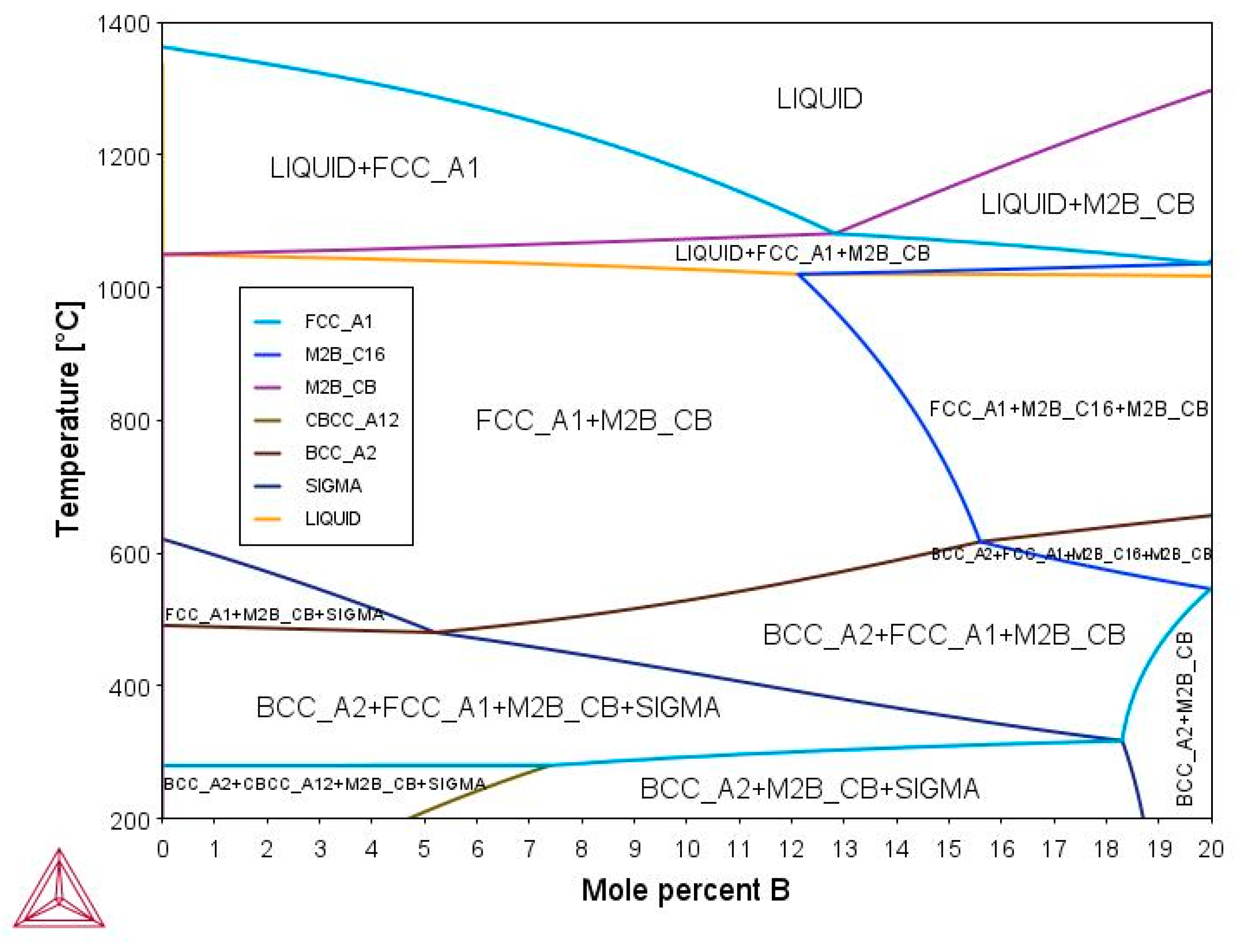
Figure 1. Pseudobinary phase diagram for (Fe50Mn30Cr10Co10)-xBx system.
Materials 16 05579 g001
Figure 2. Molar fraction of stable phases as a function of temperature.
Materials 16 05579 g002
Figure 3. Molar fraction of elements in phases as a function of temperature.
Materials 16 05579 g003
Figure 4. Structural parameters and octahedral cavity for the FCC alloys (Fe50Mn30Cr10Co10)-xBx (x = 0, 5, 7, 10, and 15 at.%) obtained with SQS + DFT. All values given are in Angstrom (Å). Red spheres = iron, magenta spheres = manganese, green spheres = cobalt, blue spheres = Chromium and yellow spheres = boron.
Materials 16 05579 g004
Figure 5. Structural parameters and octahedral cavity for the HCP alloys (Fe50Mn30Cr10Co10)-xBx (x = 0, 5, 7, 10, and 15 at.%) obtained with SQS + DFT. All values given are in Angstrom (Å). Red spheres = iron, magenta spheres = manganese, green spheres = cobalt, blue spheres = Chromium and yellow spheres = boron.
Materials 16 05579 g005
Figure 6. Structural parameters of a 3 × 3 × 3 cell of orthorhombic (Cr,Fe)2B and tetrahedral (Fe,Cr)2B.
Materials 16 05579 g006
Table 1. Criteria and parameters used to determine the stability of the solid solution.
CriteriaParametersRange
MC1 δ r 0.5 % < δ r < 6.5 %
H m i x 17.5   kJ / mol < Hmix < 5   kJ / mol
MC2 Ω Ω   1.1
δ r δ r   6.6 %
MC7 T / T m 0.9 < T / T m
H m i x 15   kJ / mol < Hmix < 5   kJ / mol
δ r δ r ≤ 6.6%
T / T m 0.5     T / T m < 0.9
H m i x H m i x 7.5   kJ / mol
δ r δ r ≤ 3.3%
Table 2. Exact compositions and supercell compositions (at.%) corresponding to (Fe50Mn30Cr10Co10)-xBx (x = 0, 5, 7, 10, and 15 at.%).
NomenclatureExact Composition (at.%)60 Atoms’ FCC and HCP Supercell Composition
Alloy-B0Fe50Mn30Co10Cr10Fe30Mn18Co6Cr6
Alloy-B5Fe48Mn27Co10Cr10B5Fe30Mn18Co6Cr6B
Alloy-B7Fe48Mn27Co9Cr9B7Fe30Mn18Co6Cr6B2
Alloy-B10Fe45Mn27Co9Cr9B10Fe27Mn15Co9Cr9B
Alloy-B15Fe42Mn25Co9Cr9B15Fe27Mn15Co9Cr9B2
Table 3. Physical and chemical parameters for the study of the phase rules of the HEAs.
Nomenclature∆Smix (J/mol*K)∆Hmix (kJ/mol)VEC∆XPδr (%)ΩTm (K)
Alloy-B09.71−0.927.600.1323.8318.541756
Alloy-B510.94−6.197.380.1438.753.171792
Alloy-B711.02−8.077.290.14810.062.461799
Alloy-B1011.45−10.867.140.15511.731.911815
Alloy-B1511.88−15.026.910.16313.961.461848
Table 4. Formation criteria based on physical and chemical parameters using HEAPS program.
NomenclatureMC1 (∆Hmixr)MC2
(Ω-δr)
MC7
(T/Tmr-∆Hmix)
IMF1 (∆XP)
Alloy-B0SSSSIM(0.5 < T/Tm < 0.9)Uncertain
Alloy-B5IM/BMGIMIM(0.5 < T/Tm < 0.9)TCP phase
Alloy-B7IM/BMGIMIM(0.5 < T/Tm < 0.9)TCP phase
Alloy-B10IM/BMGIMIM(0.5 < T/Tm < 0.9)TCP phase
Alloy-B15IM/BMGIMIM(0.5 < T/Tm < 0.9)TCP phase
Table 5. Stacking Fault Energies (SFE) obtained with CALPHAD.
Alloys G γ
(J/mol)
G ε
(J/mol)
Δ G γ ε
(J/mol)
a
(Å)
ρ
(mol/m2)
SFE
(mJ/m2)
Alloy-B0−7327.51−7088.642393.62.96 × 10−524.19
Alloy-B5−15,300.30−14,855.364453.62.96 × 10−536.34
Alloy-B7−17,181.93−16,360.738213.62.96 × 10−556.61
Alloy-B10−17,059.02−16,206.178533.62.96 × 10−560.48
Alloy-B15−16,824.66−15,911.149133.62.96 × 10−564.08
Table 6. Root Mean Square Deviation (RMSD) to compare boron-added alloys.
PhaseAlloysRMSD
All Atoms
RMSD
All Cr
RMSD
All Mn
RMSD
All Fe
RMSD
All Co
FCCalloy-B5 vs. alloy-B72.8244.7582.7052.1633.505
HCPalloy-B5 vs. alloy-B72.2090.6713.0412.0070.666
FCCalloy-B10 vs. alloy-B152.2470.5462.2051.7264.039
HCPalloy-B10 vs. alloy-B151.6560.4410.3332.4370.310
Table 7. Total energy for the alloys studied and magnetic corrections for FCC structures.
AlloysE Total
FCC (eV)
E Total
HCP (eV)
EAFM (eV)EFM (eV)EAFM/FM (eV)
Alloy-B0−487.98−502.23−494.87−495.91−494.64
Alloy-B5−500.22−505.97−506.97−507.22−506.85
Alloy-B7−514.69−521.81−513.21−513.84−513.08
Alloy-B10−506.49−504.27−506.76−506.85−506.53
Alloy-B15−513.18−511.34−515.10−515.23−514.99
Table 8. Enthalpy of formation for the alloys (Fe50Mn30Cr10Co10)-xBx (x = 0, 5, 7, 10, and 15 at.%). Values are in kJ/mol.
Alloys∆Hf (kJ/mol), FCC∆Hf (kJ/mol), HCP
Alloy-B0−14.09−14.19
Alloy-B5−14.08−14.24
Alloy-B7−14.44−14.33
Alloy-B10−14.26−14.18
Alloy-B15−14.39−14.34
Table 9. Stacking Fault Energies (SFE) obtained with DFT.
AlloysΔEHCP-FCC (eV)SFEANNI (mJ/m2)SFEANNI+M2B (mJ/m2)
Alloy-B06.6620.74-
Alloy-B55.7518.34-
Alloy-B77.1123.00-
Alloy-B102.226.1852.55
Alloy-B151.845.0751.44
Disclaimer/Publisher’s Note: The statements, opinions and data contained in all publications are solely those of the individual author(s) and contributor(s) and not of MDPI and/or the editor(s). MDPI and/or the editor(s) disclaim responsibility for any injury to people or property resulting from any ideas, methods, instructions or products referred to in the content.