
Investigation on Thermal Barrier Coating Damages for Ultrafast Laser Drilling of Cooling Holes

Abstract
:1. Introduction
2. Experimental Design Translation
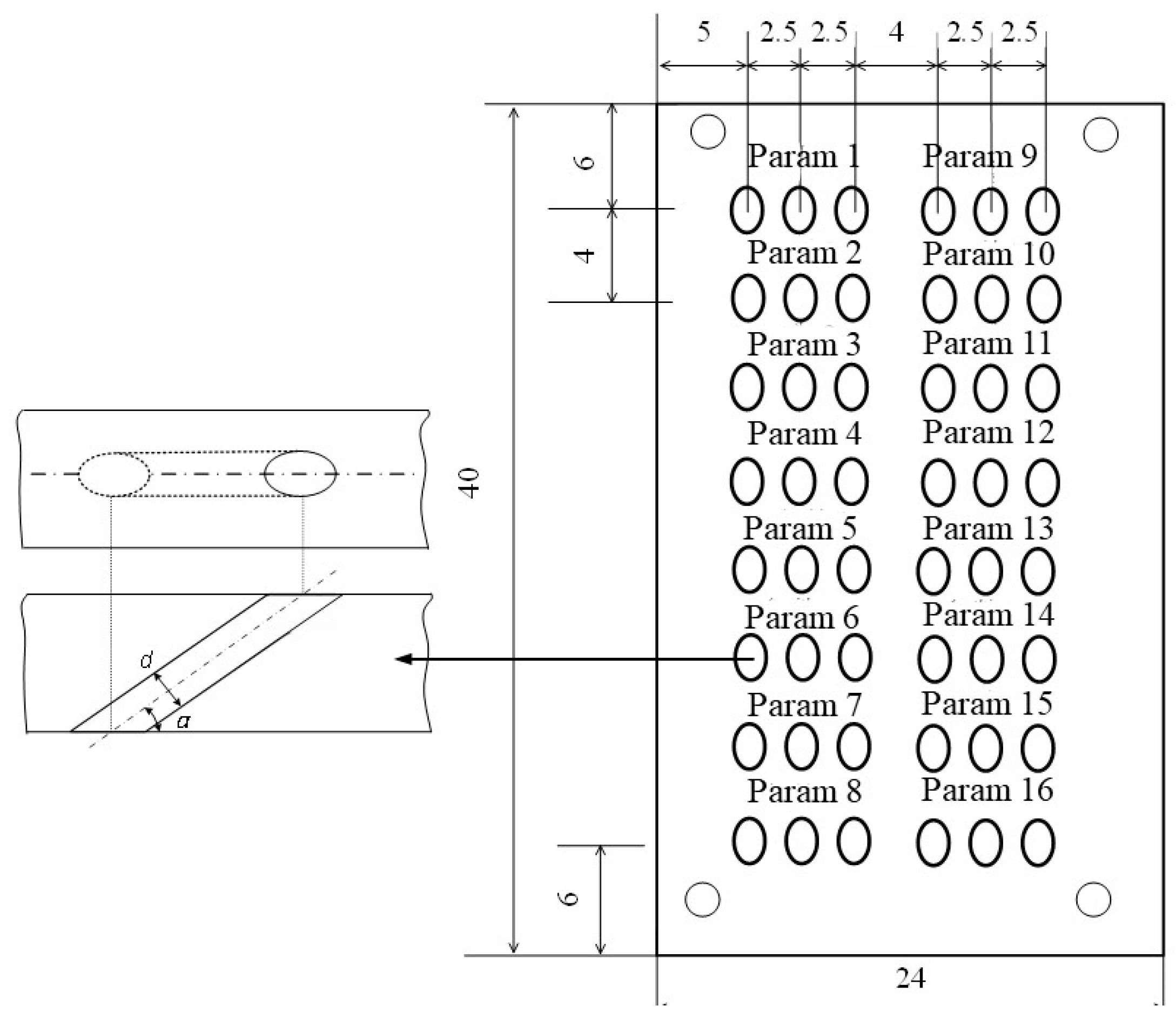
2.1. Experimental Design
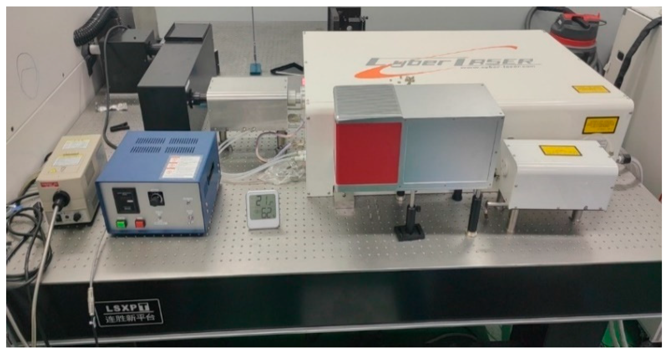
2.2. Experimental Methods and Experimental Equipment
3. Results and Discussions
3.1. Effects of Process Parameters on Coating Surface Roughness
3.2. Effects of Process Parameters on Coating Microhardness
3.3. Study on Damage to Coatings of Holes
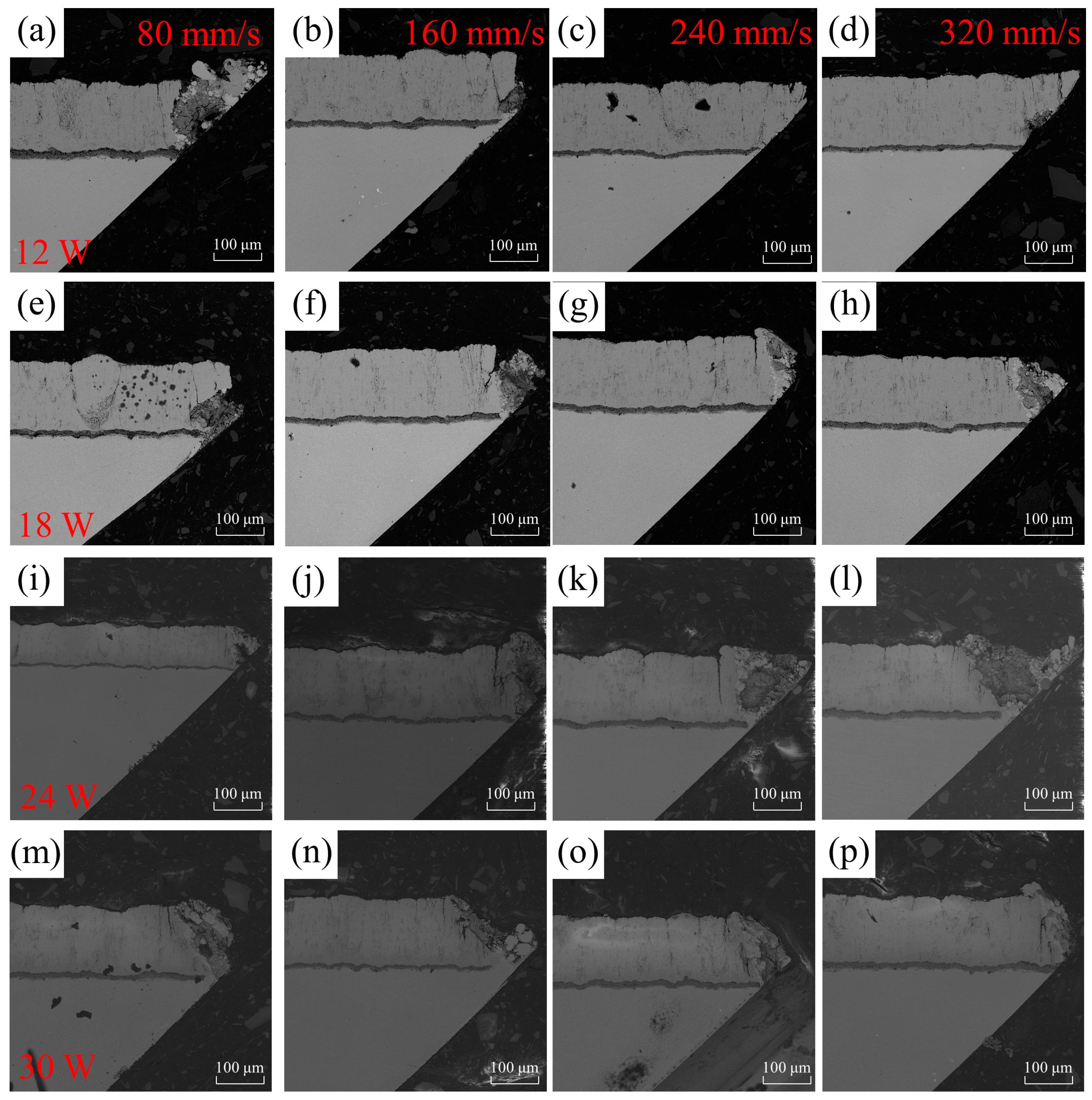
3.4. Effects of Process Parameters on Damage to Coating on the Sharp Angle Side of Holes
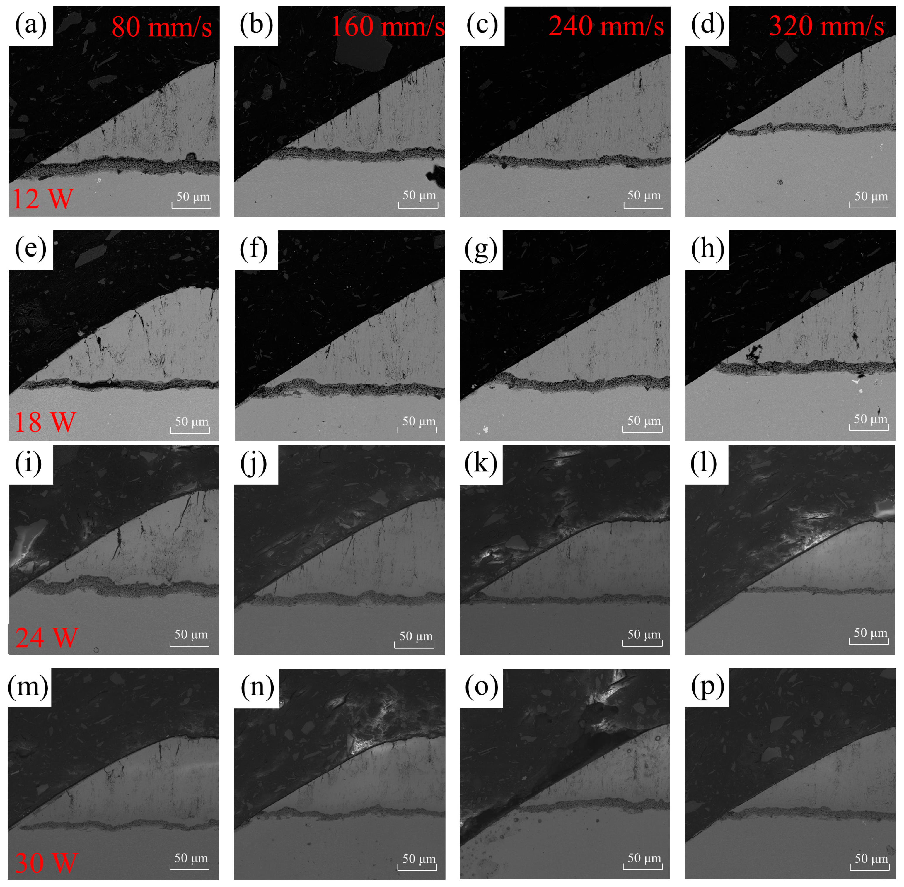
3.5. Effects of Process Parameters on Damage to Coating on the Obtuse Angle Side of Holes
4. Conclusions
- (1)
- The roughness is the lowest when the scanning speed is 320 mm/s, and the pulse energy is 12 W. The surface roughness of the coating around the holes increases with an increase in pulse energy at the same scanning speed. The sharp edge is significantly affected by picosecond laser processing, resulting in a relatively uneven coating surface.
- (2)
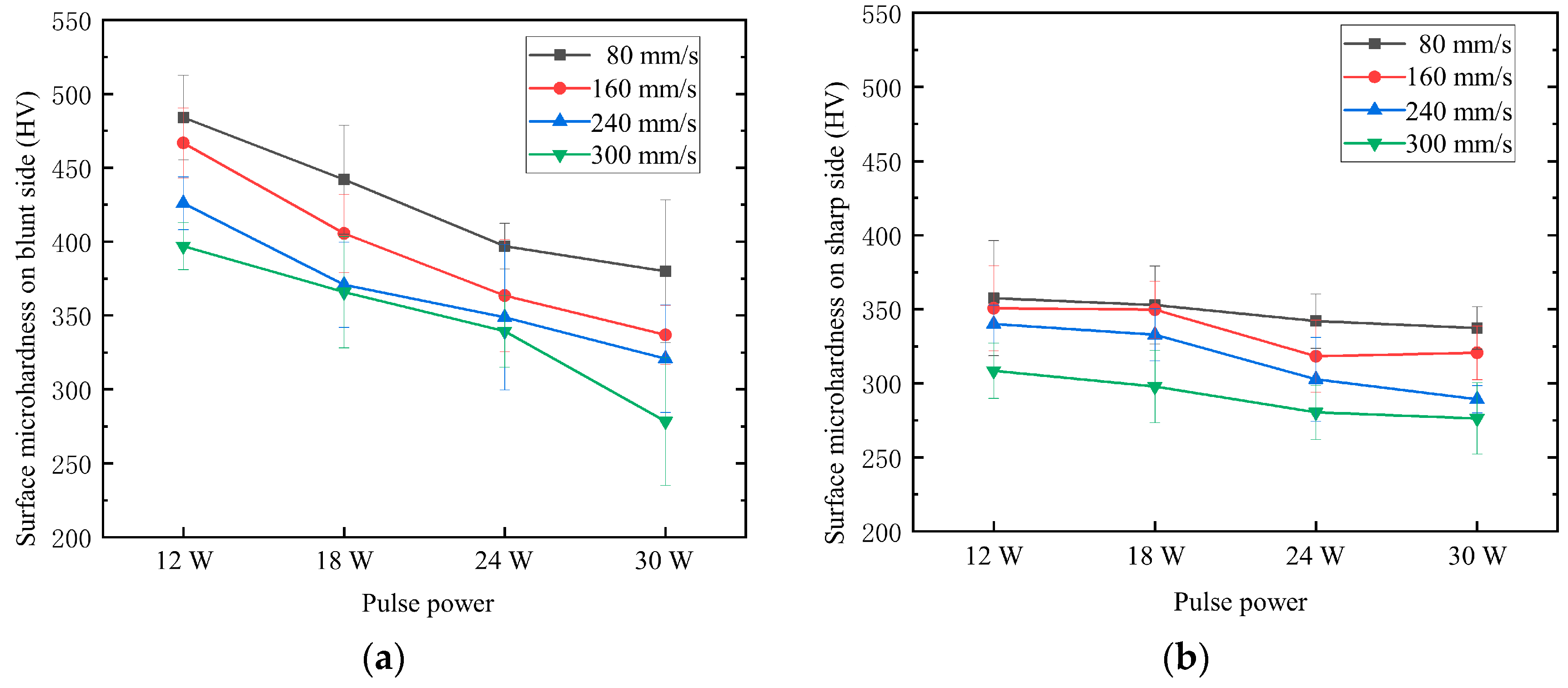
- The microhardness of the coating on the obtuse-angle side of the hole perimeter is generally higher than that on the acute-angle side. This is attributed to the greater influence of molten material ejected from the substrate and accumulated on the surface of the thermal barrier coating on the acute-angle side. Furthermore, the trend of change in microhardness is the same for both blunt and sharp edges, decreasing with increasing pulse energy and scanning speed.
- (3)
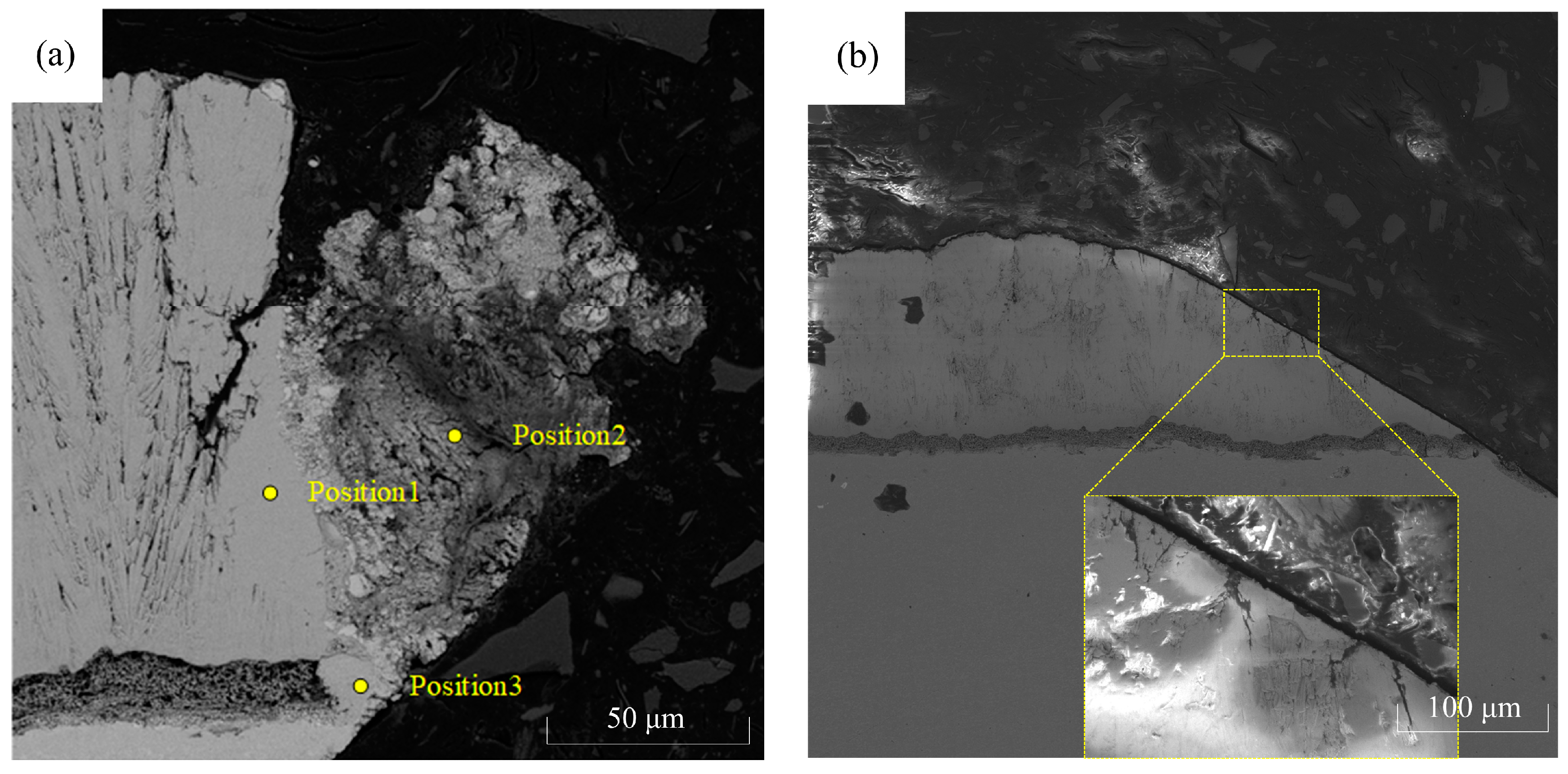
- During the fabrication of thermal barrier coating film holes using a picosecond laser, due to the different ablation thresholds between the coating and substrate, the coating on the sharp edge suffers from damage and detachment due to excessive thermal stress, while microcracks are generated on the blunt edge.
- (4)
- The best quality of the hole perimeter is achieved with a pulse energy of 12 W and a scanning speed of 320 mm/s, while the worst quality is observed with a pulse energy of 30 W and a scanning speed of 80 mm/s. When using low pulse energy and high scanning speed, the damage area on the sharp edge of the gas film hole is smaller, and the crack length on the blunt edge is relatively smaller.
- (5)
- The minimum average crack length and the best processing quality on the blunt edge are achieved with a scanning speed of 320 mm/s and pulse energy of 30 W. The maximum crack length and the widest crack dispersion, indicating the poorest processing quality on the blunt edge, are observed with a scanning speed of 80 mm/s and a pulse energy of 24 W.
Author Contributions
Funding
Institutional Review Board Statement
Informed Consent Statement
Data Availability Statement
Acknowledgments
Conflicts of Interest
References
- Zhang, H.; Gou, J.; Yin, P.; Su, X.; Yuan, X. Film-cooling hole optimization and experimental validation considering the lateral pressure gradient. Front. Mech. Eng. 2023, 6, 193–198. [Google Scholar] [CrossRef]
- Li, M.; Wen, Z.; Wang, P.; Liu, Y.; Li, Z.; Yue, Z. Femtosecond laser high-quality drilling of film cooling holes in nickel-based single superalloy for turbine blades with a two-step helical drilling method. J. Mater. Process. Technol. 2023, 312, 177827. [Google Scholar] [CrossRef]
- He, W.; He, S.; Du, J.; Ming, W.; Ma, J.; Cao, Y.; Li, X. Fiber orientations effect on process performance for wire cut electrical discharge machining (WEDM) of 2D C/SiC composite. Int. J. Adv. Manuf. Technol. 2019, 102, 507–518. [Google Scholar] [CrossRef]
- Diaz, O.G.; Luna, G.G.; Liao, Z.; Axinte, D. The new challenges of machining Ceramic Matrix Composites (CMCs): Review of surface integrity. Int. J. Mach. Tools Manuf. 2019, 139, 24–36. [Google Scholar] [CrossRef]
- Wang, R.; Dong, X.; Wang, K.; Sun, X.; Fan, Z.; Duan, W. Investigation on millijoule femtosecond laser spiral drilling of micro-deep holes in thermal barrier coated alloys. Int. J. Adv. Manuf. Technol. 2021, 144, 3257–3271. [Google Scholar] [CrossRef]
- Wang, R.; Dong, X.; Wang, K.; Sun, X.; Fan, Z.; Duan, W. Two-step approach to improving the quality of laser micro-hole drilling on thermal barrier coated nickel base alloys. Opt. Lasers Eng. 2019, 121, 406–415. [Google Scholar] [CrossRef]
- Lu, C.; Duan, W.; Wang, K.; Wang, R.; Tang, Z. Experiments of drilling micro-holes on superalloy with thermal barrier coatings by using femtosecond laser. Ferroelectrics 2020, 564, 37–51. [Google Scholar] [CrossRef]
- Bathe, P. Evaluation of laser drilling of holes in thermal barrier coated superalloys. Mater. Sci. Technol. 2014, 30, 1778–1782. [Google Scholar] [CrossRef]
- Sezer, H.K.; Li, L.; Schmidt, M.; Pinkerton, A.J.; Anderson, B.; Williams, P. Effect of beam angle on HAZ, recast and oxide layer characteristics in laser drilling of TBC nickel superalloys. Int. J. Mach. Tools Manuf. 2006, 46, 1972–1982. [Google Scholar] [CrossRef]
- Sezer, H.K.; Pinkerton, A.J.; Li, L.; Byrd, P. An investigation into delamination mechanisms in inclined laser drilling of thermal barrier coated aerospace superalloys. J. Laser Appl. 2005, 17, 225–234. [Google Scholar] [CrossRef]
- Liu, H.; Zhao, W.; Wang, L.; Shen, X.; Wang, N.; Wang, X. Percussion Drilling of Deep Holes Using Picosecond Ultrashort Pulse Laser in Ni-Based Superalloy Coated with Ceramic Thermal Barrier Coatings. Materials 2020, 13, 3570. [Google Scholar] [CrossRef]
- Yu, Y.; Zhou, L.; Cai, Z.; He, W. DD6 single-crystal superalloy with thermal barrier coating in femtosecond laser percussion drilling. Opt. Laser Technol. 2021, 133, 106555. [Google Scholar] [CrossRef]
- Marimuthu, S.; Smith, B.; Kiely, A.; Liu, Y. Millisecond pulse laser machining of thermal barrier coatings. CIRP J. Manuf. Sci. Technol. 2020, 28, 107–117. [Google Scholar] [CrossRef]
- Marimuthu, S.; Smith, B.; Kiely, A.; Liu, Y. Delamination-free millisecond laser drilling of thermal barrier coated aerospace alloys. J. Laser Appl. 2019, 31, 042001. [Google Scholar] [CrossRef]
- Marimuthu, S.; Smith, B. Water-jet guided laser drilling of thermal barrier coated aerospace alloy. Int. J. Adv. Manuf. Technol. 2021, 113, 177–191. [Google Scholar] [CrossRef]
- Zhai, Z.; Wang, W.; Mei, X.; Li, M.; Li, X. Percussion drilling on nickel-based alloy with thermal barrier coatings using femtosecond laser. Optik 2019, 194, 163066. [Google Scholar] [CrossRef]
- Zhai, Z.; Wang, W.; Mei, X. Simulation and experimental study on laser drilling of nickel-based alloy with thermal barrier coatings. Int. J. Adv. Manuf. Technol. 2017, 90, 1871–1879. [Google Scholar] [CrossRef]
- Gupta, U.; Nath, A.K.; Bandyopadhyay, P.P. Laser micro-hole drilling in thermal barrier coated nickel based superalloy. IOP Conf. Ser. Mater. Sci. Eng. 2016, 149, 012076. [Google Scholar] [CrossRef]
- Zheng, C.; Zhao, K.; Shen, H.; Zhao, X.; Yao, Z. Crack behavior in ultrafast laser drilling of thermal barrier coated nickel superalloy. J. Mater. Process. Technol. 2019, 282, 116678. [Google Scholar] [CrossRef]
- Fan, Z.; Dong, X.; Wang, K.; Duan, W.; Wang, R.; Mei, X.; Wang, W.; Cui, J.; Yuan, X.; Xu, C. Effect of drilling allowance on TBC delamination, spatter and re-melted cracks characteristics in laser drilling of TBC coated superalloys. Int. J. Mach. Tools Manuf. 2016, 106, 1–10. [Google Scholar] [CrossRef]
- Das, D.K.; Pollock, T.M. Femtosecond laser machining of cooling holes in thermal barrier coated CMSX4 superalloy. J. Mater. Process. Technol. 2009, 209, 5661–5668. [Google Scholar] [CrossRef]
- Zhang, Z.; Wang, W.; Jin, C.; Jiang, R.; Xiong, Y.; Zhang, X.; Mao, Z. Investigation on efficiency and quality for ultrashort pulsed laser ablation of nickel-based single crystal alloy DD6. Int. J. Adv. Manuf. Technol. 2021, 114, 883–897. [Google Scholar] [CrossRef]
- Zhang, Z.; Wang, W.; Jiang, R.; Zhang, X.; Xiong, Y.; Mao, Z. Investigation on geometric precision and surface quality of microholes machined by ultrafast laser. Opt. Laser Technol. 2020, 121, 105834. [Google Scholar] [CrossRef]


| Parameters | Average Power | Scanning Speed |
|---|---|---|
| 1 | 12 W | |
| 2 | ||
| 3 | ||
| 4 | ||
| 5 | 18 W | |
| 6 | ||
| 7 | ||
| 8 | ||
| 9 | 24 W | |
| 10 | ||
| 11 | ||
| 12 | ||
| 13 | 30 W | |
| 14 | ||
| 15 | ||
| 16 |
| Parameters | Symbol | Values |
|---|---|---|
| Pulse width | 2.1 ps | |
| Diameter of the focal point | df | 48 μm |
| Repetition rate | f | 75 kHz |
| Maximum average power | Pmax | 30 W |
| Maximum peak power | 190.4 MW | |
| Maximum pulse energy | Emax | 0.4 J |
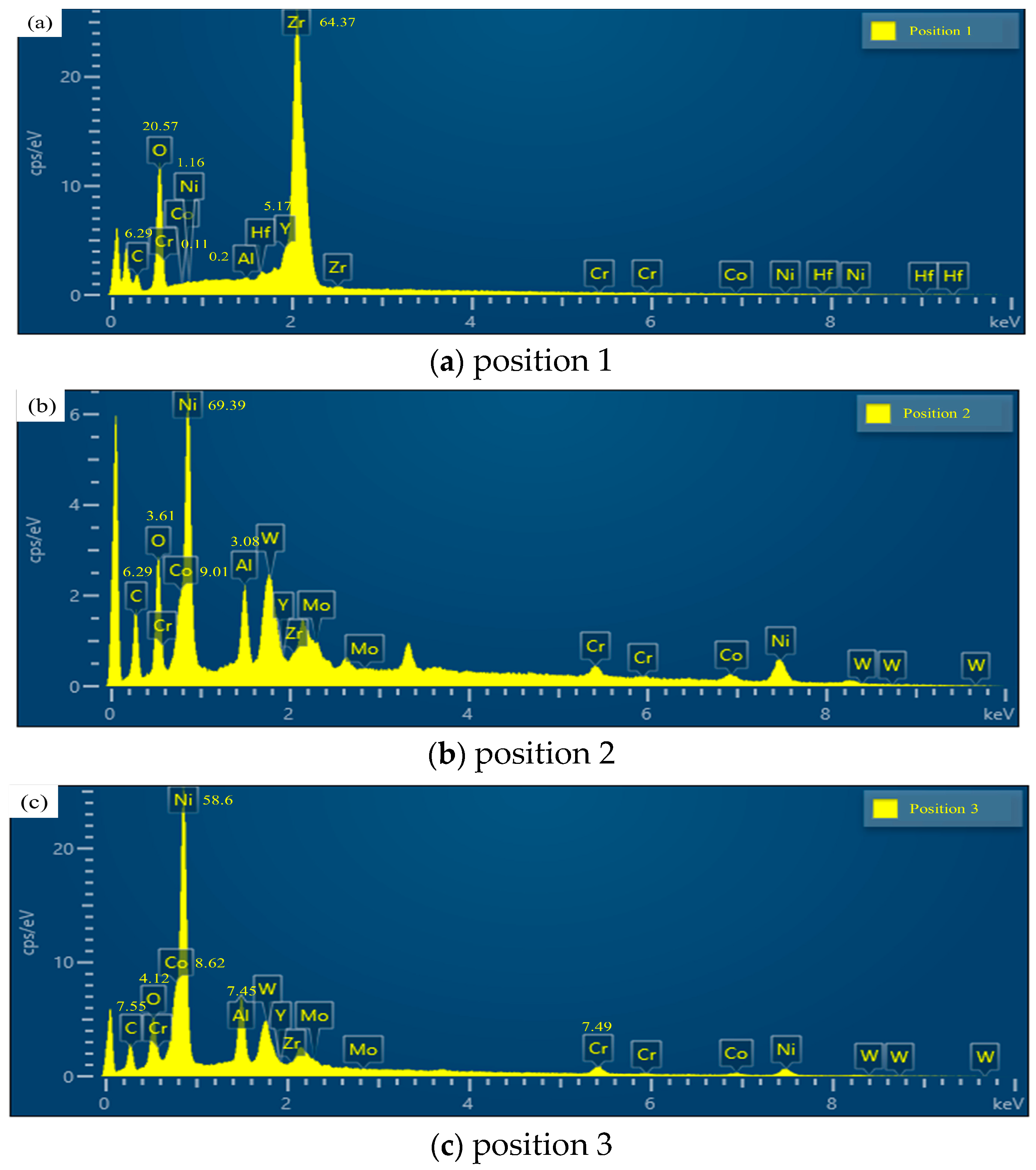
| Element | C | O | Al | Cr | Co | Ni | Y | Zr |
|---|---|---|---|---|---|---|---|---|
| Position 1 | 6.29 | 20.57 | 0.2 | 0.11 | 0 | 1.16 | 5.17 | 64.37 |
| Position 2 | 6.29 | 3.61 | 3.08 | 3.62 | 9.01 | 69.39 | 0 | 0 |
| Position 3 | 7.55 | 4.12 | 7.45 | 7.49 | 8.62 | 58.6 | 0 | 0 |
| Scanning Speed | 80 mm/s | 160 mm/s | 240 mm/s | 320 mm/s | |
|---|---|---|---|---|---|
| Pulse Energy | |||||
| 40% | 19,000 | 10,200 | 540 | 95.7 | |
| 60% | 14,400 | 13,200 | 12,300 | 11,600 | |
| 80% | 20,400 | 17,400 | 14,700 | 12,100 | |
| 100% | 23,300 | 19,100 | 16,200 | 12,400 | |
Disclaimer/Publisher’s Note: The statements, opinions and data contained in all publications are solely those of the individual author(s) and contributor(s) and not of MDPI and/or the editor(s). MDPI and/or the editor(s) disclaim responsibility for any injury to people or property resulting from any ideas, methods, instructions or products referred to in the content. |
© 2023 by the authors. Licensee MDPI, Basel, Switzerland. This article is an open access article distributed under the terms and conditions of the Creative Commons Attribution (CC BY) license (https://creativecommons.org/licenses/by/4.0/).
Share and Cite
Wang, S.; Hu, Y.; Zuo, Y.; Yang, Z.; Jiang, R. Investigation on Thermal Barrier Coating Damages for Ultrafast Laser Drilling of Cooling Holes. Materials 2023, 16, 5395. https://doi.org/10.3390/ma16155395
Wang S, Hu Y, Zuo Y, Yang Z, Jiang R. Investigation on Thermal Barrier Coating Damages for Ultrafast Laser Drilling of Cooling Holes. Materials. 2023; 16(15):5395. https://doi.org/10.3390/ma16155395
Chicago/Turabian StyleWang, Shaojian, Yue Hu, Yangjie Zuo, Zenan Yang, and Ruisong Jiang. 2023. "Investigation on Thermal Barrier Coating Damages for Ultrafast Laser Drilling of Cooling Holes" Materials 16, no. 15: 5395. https://doi.org/10.3390/ma16155395
APA StyleWang, S., Hu, Y., Zuo, Y., Yang, Z., & Jiang, R. (2023). Investigation on Thermal Barrier Coating Damages for Ultrafast Laser Drilling of Cooling Holes. Materials, 16(15), 5395. https://doi.org/10.3390/ma16155395