

Graphene Enhances the Loading Capacity and Lubrication Performance of Ionic Liquids: A Molecular Dynamics Study

(This article belongs to the Section Manufacturing Processes and Systems)
Abstract
1. Introduction
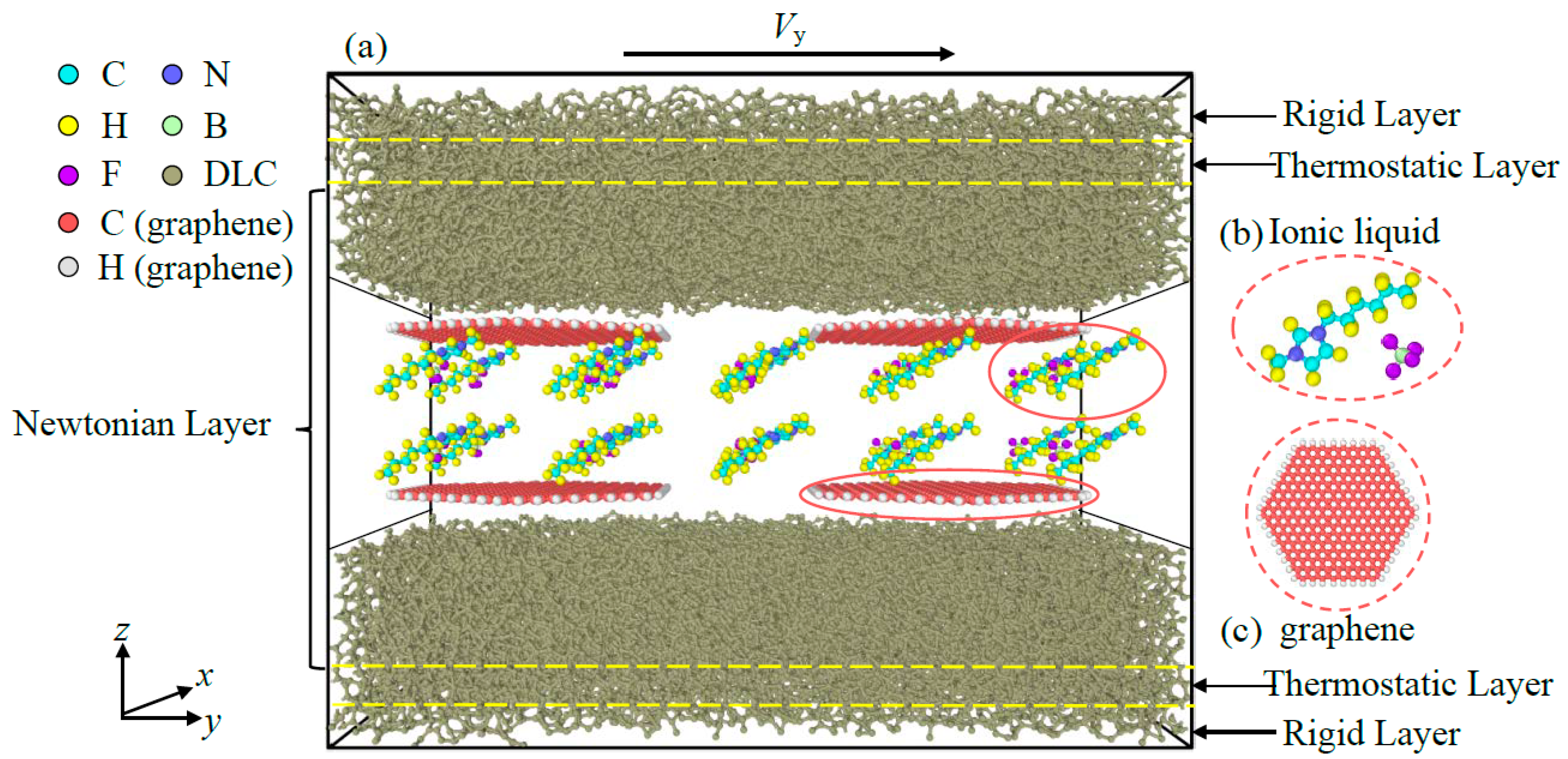
2. Modeling
3. Results
3.1. Friction Behaviors with Different Normal Stress and Amounts of Graphene
3.2. Friction Behaviors with Different Amounts of Ionic Liquids
3.3. Friction Behaviors with Different Surface Roughness
3.4. Friction Behaviors with Different Sliding Velocity
4. Discussion
5. Conclusions
- (1)
- Graphene as lubricant additives can improve the lubrication performance of ILs at all given conditions. The reduction reach up to 88%. The improved tribological properties of composite lubricants are attributed to the fact that intact graphene prevents direct contact of the friction pairs interface, but fail under high normal stress due to structure rupture.
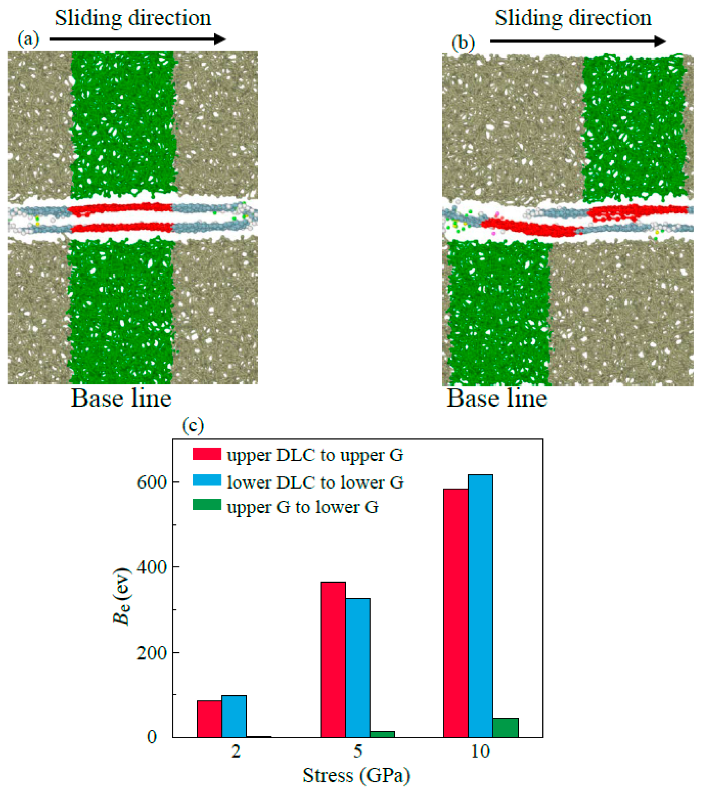
- (2)
- Multilayer graphene has better friction-reducing performance and better friction durability compared to monolayer structure. The antifriction performance is ascribed to the easy-shear property between the multilayer graphene layers with super-low binding energy, which is 5% of the binding energy between the DLC and the graphene. The friction durability is due to the decrease in the percentage of high tensile stress sites which ensures that the multilayer graphene has a more stable structure in lubrication.
- (3)
- The lubricating performance of the compound lubricating oil is sensitive to Ni. Void space occurring under insufficient Ni in lubrication film makes the Fn acting on graphene higher than the theoretical value, which then makes graphene prone to rupturing under the same theoretical pressure. Over-thick IL film and graphene form a three-body abrasive wear structure with stress concentration in the graphene, and eventually lead to degradation of tribological performance of the compound lubricant.
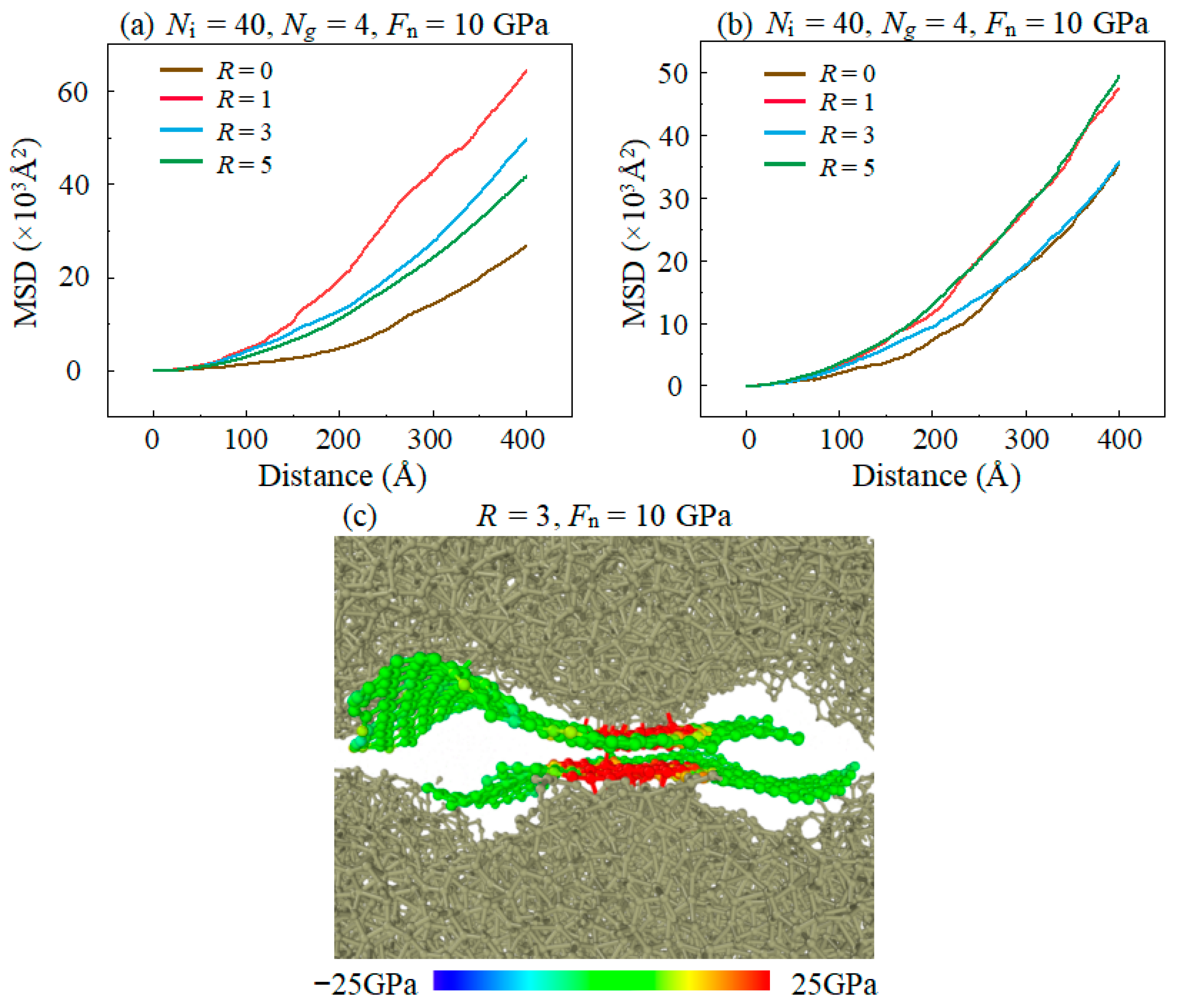
- (4)
- Both the rough surface of the substrate and the high sliding speed affects the lubricating properties of the lubricant, which is caused by the excessively concentrated stress in the graphene plane, promoting the bond formations between graphene and DLC substrates. In addition, it is found that graphitization caused by high temperature effectively reduces friction in the stable stage in high speed.
- (5)
- The results of this study explain the basic friction mechanism of graphene additives in ionic liquid lubricants, and provide a reference for the development of new fluid lubricants by adjusting the content of graphene, normal stress and the thickness of ionic liquid lubrication film to meet potential applications.
Author Contributions
Funding
Institutional Review Board Statement
Informed Consent Statement
Data Availability Statement
Acknowledgments
Conflicts of Interest
References
- Ye, C.F.; Liu, W.M.; Chen, Y.X.; Yu, L.G. Room-temperature ionic liquids: A novel versatile lubricant. Chem. Commun. 2001, 21, 2244–2245. [Google Scholar] [CrossRef]
- Lertola, A.C.; Wang, B.; Li, L. Understanding the Friction of Nanometer-Thick Fluorinated Ionic Liquids. Ind. Eng. Chem. Res. 2018, 57, 11681–11685. [Google Scholar] [CrossRef]
- Omiya, T.; Fontes, M.; Vuchkov, T.; Cruz, S.; Cavaleiro, A.; Ferreira, F. Tribological Performance of Gd-DLC and Eu-DLC Coatings in the Presence of Synthetic Oils Containing Ionic Liquid Additives. Tribol. Lett. 2023, 71, 65. [Google Scholar] [CrossRef]
- Li, C.; Wang, G.; Han, Q.; Feng, G.; Wang, L.; Wang, S. Effects of current-carrying conditions on lubrication and tribological performance of ionic liquid. J. Mol. Liq. 2022, 367, 120471. [Google Scholar] [CrossRef]
- Kondrat, S.; Feng, G.; Bresme, F.; Urbakh, M.; Kornyshev, A.A. Theory and Simulations of Ionic Liquids in Nanoconfinement. Chem. Rev. 2023, 123, 6668–6715. [Google Scholar] [CrossRef]
- Sadeghi, M.; Omiya, T.; Fernandes, F.; Vilhena, L.; Ramalho, A.; Ferreira, F. Tribological Behavior of Doped DLC Coatings in the Presence of Ionic Liquid Additive under Different Lubrication Regimes. Coatings 2023, 13, 891. [Google Scholar] [CrossRef]
- Ji, M.; Liu, S.; Xiao, H.; Li, H. Investigation on tribological performance of Ionic liquid filled microcapsules as additives under water-based drilling mud conditions. Tribol. Int. 2023, 184, 108439. [Google Scholar] [CrossRef]
- Donato, M.T.; Deuermeier, J.; Colaço, R.; Branco, L.C.; Saramago, B. New Protic Ionic Liquids as Potential Additives to Lubricate Si-Based MEMS/NEMS. Molecules 2023, 28, 2678. [Google Scholar] [CrossRef]
- Cai, M.; Yu, Q.; Liu, W.; Zhou, F. Ionic liquid lubricants: When chemistry meets tribology. Chem. Soc. Rev. 2020, 49, 7753–7818. [Google Scholar] [CrossRef]
- Lhermerout, R.; Diederichs, C.; Perkin, S. Are Ionic Liquids Good Boundary Lubricants? A Molecular Perspective. Lubricants 2018, 6, 9. [Google Scholar] [CrossRef]
- Zhang, C.; Zhang, X.; Zhang, W.; Zhao, Z.; Fan, X. Functionalized Graphene from Electrochemical Exfoliation of Graphite toward Improving Lubrication Function of Base Oil. Lubricants 2023, 11, 166. [Google Scholar] [CrossRef]
- Jiang, H.; Hou, X.; Ma, Y.; Guan, W.; Liu, H.; Qian, Y. Elaboration of Ionic Liquids on the Anti-Wear Performance of the Reinforced Steel-Steel Contact Surface. Lubricants 2022, 10, 260. [Google Scholar] [CrossRef]
- Zhang, L.; Pu, J.; Wang, L.; Xue, Q. Frictional dependence of graphene and carbon nanotube in diamond-like carbon/ionic liquids hybrid films in vacuum. Carbon 2014, 80, 734–745. [Google Scholar] [CrossRef]
- Wu, J.; Zhu, J.; Mu, L.; Shi, Y.; Dong, Y.; Feng, X.; Lu, X. High load capacity with ionic liquid-lubricated tribological system. Tribol. Int. 2016, 94, 315–322. [Google Scholar] [CrossRef]
- Lv, M.; Han, F.; Wang, Q.; Wang, T.; Liang, Y. The structure properties and tribological behavior of the ionic liquid–polyimide composite films under high-vacuum environment. High Perform. Polym. 2016, 29, 170–177. [Google Scholar] [CrossRef]
- Zhang, L.; Zhang, Z.; Gao, X.A.; Matlan, S.J.; Taha, N.A. The Preparations of Fluorographene Nanosheets and Research in Tribological Properties in High Vacuum. Materials 2023, 16, 3929. [Google Scholar] [CrossRef]
- Han, K.; Zhang, Y.; Song, N.; Yu, L.; Zhang, P.; Zhang, Z.; Qian, L.; Zhang, S. The Current Situation and Future Direction of Nanoparticles Lubricant Additives in China. Lubricants 2022, 10, 312. [Google Scholar] [CrossRef]
- Sanes, J.; Avilés, M.-D.; Saurín, N.; Espinosa, T.; Carrión, F.-J.; Bermúdez, M.-D. Synergy between graphene and ionic liquid lubricant additives. Tribol. Int. 2017, 116, 371–382. [Google Scholar] [CrossRef]
- Zhang, L.; Pu, J.; Wang, L.; Xue, Q. Synergistic effect of hybrid carbon nanotube-graphene oxide as nanoadditive enhancing the frictional properties of ionic liquids in high vacuum. ACS Appl. Mater. Interfaces 2015, 7, 8592–8600. [Google Scholar] [CrossRef]
- Washizu, H.; Kajita, S.; Tohyama, M.; Ohmori, T.; Nishino, N.; Teranishi, H.; Suzuki, A. Mechanism of ultra low friction of multilayer graphene studied by coarse-grained molecular simulation. Faraday Discuss. 2012, 156, 279–291. [Google Scholar] [CrossRef]
- Ge, X.; Chai, Z.; Shi, Q.; Liu, Y.; Wang, W. Graphene superlubricity: A review. Friction 2023, 11, 1–21. [Google Scholar] [CrossRef]
- Yu, K.; Peng, Y.; Lang, H.; Ding, S.; Huang, Y. Material transfer mechanism for fabrication of superlubricity interface by reciprocating rubbing on graphite under high contact stress. Carbon 2022, 188, 420–430. [Google Scholar] [CrossRef]
- Rasheed, A.K.; Khalid, M.; Rashmi, W.; Gupta, T.C.S.M.; Chan, A. Graphene based nanofluids and nanolubricants—Review of recent developments. Renew. Sustain. Energy Rev. 2016, 63, 346–362. [Google Scholar] [CrossRef]
- Xu, Y.; Peng, Y.; Dearn, K.D.; Zheng, X.; Yao, L.; Hu, X. Synergistic lubricating behaviors of graphene and MoS2 dispersed in esterified bio-oil for steel/steel contact. Wear 2015, 342–343, 297–309. [Google Scholar] [CrossRef]
- Mu, L.; Cao, D.; Zhuang, W.; Yu, Q.; Cai, M.; Shi, Y. Stable Dispersed Zeolitic Imidazolate Framework/Graphene Oxide Nanocomposites in Ionic Liquids Resulting in High Lubricating Performance. Adv. Mater. Interfaces 2020, 7, 1902194. [Google Scholar] [CrossRef]
- Jibin, P.; Wan, S.; Zhao, W.; Mo, Y.; Zhang, X.; Wang, L.; Xue, Q. Preparation and Tribological Study of Functionalized GrapheneÀIL Nanocomposite Ultrathin Lubrication Films on Si Substrates. J. Phys. Chem. C 2011, 115, 13275–13284. [Google Scholar]
- Qi, Y.E.; Zhang, L.; Wang, Y. Insight into the Effect of TDMs on the Tribological Behaviors of the Ionic Liquid Composite Films. Materials 2020, 13, 191. [Google Scholar] [CrossRef]
- Saurín, N.; Sanes, J.; Bermúdez, M.-D. New Graphene/Ionic Liquid Nanolubricants. Mater. Today Proc. 2016, 3, S227–S232. [Google Scholar] [CrossRef]
- Wei, X.; Zhao, Y.; Zhang, L.; Wang, J.; Wang, L.; Xi, D. Effects of ionic liquid on the dispersion and tribological property of graphene lubricant. Lubr. Sci. 2020, 32, 415–423. [Google Scholar] [CrossRef]
- Gao, G.T.; Mikulski, P.T.; Harrison, J.A. Molecular-scale tribology of amorphous carbon coatings: Effects of film thickness, adhesion, and long-range interactions. J. Am. Chem. Soc. 2002, 124, 7202–7209. [Google Scholar] [CrossRef]
- Liu, Y.; Zhang, H.; Luo, Y.; Wang, L.; Xiao, C. Probing the low friction mechanism of hydrogen-free DLC film in oxygen and nitrogen environments by first-principles calculations and molecular dynamics simulation. Surf. Coat. Technol. 2023, 455, 129219. [Google Scholar] [CrossRef]
- Gupta, S.; Sachan, R.; Narayan, J. Scale-up of Q-carbon and nanodiamonds by pulsed laser annealing. Diam. Relat. Mater. 2019, 99, 107531. [Google Scholar] [CrossRef]
- Stukowski, A. Visualization and analysis of atomistic simulation data with OVITO–the Open Visualization Tool. Model. Simul. Mater. Sci. Eng. 2009, 18, 015012. [Google Scholar] [CrossRef]
- Sambasivarao, S.V.; Acevedo, O. Development of OPLS-AA Force Field Parameters for 68 Unique Ionic Liquids. J. Chem. Theory Comput. 2009, 5, 1038–1050. [Google Scholar] [CrossRef] [PubMed]
- Sha, H.; Tetiker, G.; Woytowitz, P.; Faller, R. Molecular Simulation Study of Aluminum—Noble Gas Interfacial Thermal Accommodation Coefficients: Thermodynamics and Molecular-Scale Phenomena. AIChE J. 2017, 64, 338–345. [Google Scholar] [CrossRef]
- Chen, J.; Li, A.; Huang, Z.; Jiang, W.; Xi, G. Numerical study on CO2 non-equilibrium condensation considering shock waves for the potential of flue gas decarbonization. Int. Commun. Heat Mass Transf. 2023, 144, 106749. [Google Scholar] [CrossRef]
- Berman, D.; Erdemir, A.; Sumant, A.V. Graphene: A new emerging lubricant. Mater. Today 2014, 17, 31–42. [Google Scholar] [CrossRef]
- Li, J.; Peng, Y.; Tang, X.; Xu, Q.; Liu, B.; Bai, L. Lubrication Performance of Hydrogenated Graphene on Diamond-Like Carbon Films Based on Molecular Dynamics Simulation. Tribol. Lett. 2021, 69, 12. [Google Scholar] [CrossRef]
- Jeng, Y.-R.; Su, C.C.; Lay, Y.T. Effects of cohesive energy on tribological performance of nanoscale sliding systems under different force fields. J. Chin. Inst. Eng. 2007, 30, 231–240. [Google Scholar] [CrossRef]
- Sang, L.V.; Sugimura, N.; Khajeh, K.; Washizu, H. Solid Lubricants of Combined Graphene and Iron Nanoparticles for Study of Friction and Stability. Langmuir 2022, 38, 1860–1868. [Google Scholar] [CrossRef]
- Sang, L.V.; Sugimura, N.; Washizu, H. Graphene as solid lubricant vertically buried into iron contact surface by annealing for superlubricity. Tribol. Int. 2022, 165, 107288. [Google Scholar] [CrossRef]
- Wang, L.; Gong, P.; Li, W.; Luo, T.; Cao, B. Mono-dispersed Ag/Graphene nanocomposite as lubricant additive to reduce friction and wear. Tribol. Int. 2020, 146, 106228. [Google Scholar] [CrossRef]
- Aviles, M.D.; Pamies, R.; Sanes, J.; Bermudez, M.D. Graphene-Ionic Liquid Thin Film Nanolubricant. Nanomaterials 2020, 10, 535. [Google Scholar] [CrossRef]
- Wang, Y.; Xu, J.; Zhang, J.; Chen, Q.; Ootani, Y.; Higuchi, Y.; Ozawa, N.; Martin, J.M.; Adachi, K.; Kubo, M. Tribochemical reactions and graphitization of diamond-like carbon against alumina give volcano-type temperature dependence of friction coefficients: A tight-binding quantum chemical molecular dynamics simulation. Carbon 2018, 133, 350–357. [Google Scholar] [CrossRef]
- Han, Y.Y.; Qiao, D.; Sun, L.M.; Feng, D.P. Functional alkylimidazolium ionic liquids as lubricants for steel/aluminum contact: Influence of the functional groups on tribological performance. Tribol. Int. 2018, 119, 766–774. [Google Scholar] [CrossRef]
- He, T.; Dai, Q.; Huang, W.; Wang, X. Colloidal suspension of graphene oxide in ionic liquid as lubricant. Appl. Phys. A 2018, 124, 777. [Google Scholar] [CrossRef]
- Li, C.; Tang, W.; Tang, X.-Z.; Yang, L.; Bai, L. A molecular dynamics study on the synergistic lubrication mechanisms of graphene/water-based lubricant systems. Tribol. Int. 2022, 167, 107356. [Google Scholar] [CrossRef]
- Jiang, H.; Yu, Y.; Tang, W.; Zhou, R.; Shi, W.; Bai, L. A molecular dynamics study on the lubrication performance of ionic liquids. J. Mater. Sci. 2022, 57, 18874–18888. [Google Scholar] [CrossRef]


Disclaimer/Publisher’s Note: The statements, opinions and data contained in all publications are solely those of the individual author(s) and contributor(s) and not of MDPI and/or the editor(s). MDPI and/or the editor(s) disclaim responsibility for any injury to people or property resulting from any ideas, methods, instructions or products referred to in the content. |
© 2023 by the authors. Licensee MDPI, Basel, Switzerland. This article is an open access article distributed under the terms and conditions of the Creative Commons Attribution (CC BY) license (https://creativecommons.org/licenses/by/4.0/).
Share and Cite
Jiang, H.; Wang, Y.; Xiong, Z.; Zhou, R.; Yang, L.; Bai, L. Graphene Enhances the Loading Capacity and Lubrication Performance of Ionic Liquids: A Molecular Dynamics Study. Materials 2023, 16, 4942. https://doi.org/10.3390/ma16144942
Jiang H, Wang Y, Xiong Z, Zhou R, Yang L, Bai L. Graphene Enhances the Loading Capacity and Lubrication Performance of Ionic Liquids: A Molecular Dynamics Study. Materials. 2023; 16(14):4942. https://doi.org/10.3390/ma16144942
Chicago/Turabian StyleJiang, Haodong, Yaoze Wang, Zhipeng Xiong, Runhua Zhou, Linyan Yang, and Lichun Bai. 2023. "Graphene Enhances the Loading Capacity and Lubrication Performance of Ionic Liquids: A Molecular Dynamics Study" Materials 16, no. 14: 4942. https://doi.org/10.3390/ma16144942
APA StyleJiang, H., Wang, Y., Xiong, Z., Zhou, R., Yang, L., & Bai, L. (2023). Graphene Enhances the Loading Capacity and Lubrication Performance of Ionic Liquids: A Molecular Dynamics Study. Materials, 16(14), 4942. https://doi.org/10.3390/ma16144942