Abstract
The endurance limit of structural mechanical components is affected by the residual stress state, which depends strongly on the manufacturing process. In general, compressive residual stresses tend to result in an increased fatigue strength. Post-manufacturing processes such as shot peening or vibratory finishing may achieve such a compressive residual stress state. But within complex components, manufacturing-process-based imperfections severely limit the fatigue strength. Thus, the interactions of imperfections, residual stress state and material strength are key aspects in fatigue design. In this work, cast steel and aluminium alloys are investigated, each of them in vibratory finished and polished surface condition. A layer-based fatigue assessment concept is extended towards stable effective mean stress state considering the elastic–plastic material behaviour. Murakami’s concept was applied to incorporate the effect of hardness change and residual stress state. Residual stress relaxation is determined by elastic–plastic simulations invoking a combined hardening model. If the effective stress ratio within the local layer-based fatigue strength is evaluated as critical distance value, a sound calculation of fatigue strength can be achieved. Summing up, the layer-based fatigue strength design is extended and features an enhanced understanding of the effective stabilized mean stress state during cyclic loading.
1. Introduction
Due to the continuously increasing requirements of our modern industrial market, focus is laid on economic and sustainable design. Lightweight engineering is often driven by topology optimization, yielding to complexly shaped components [1]. Due to benefits in castability and comparable low density, AlSi-cast alloys are broadly used in mobility industry and transport applications [2,3,4]. Besides Al-alloys, cast steel alloys play an important role as well due to improved structural load-bearing capability [5,6,7]. The geometrical complexity of cast parts results in high local load factors. Moreover, strongly varying microstructural conditions may occur due to changes in local process parameters like local solidification [8,9,10]. Such local microstructural conditions lead to varying shape and degree of porosity, affecting the local acting stress field significantly [11,12,13]. This results in a severely limited fatigue strength of imperfective cast components compared to the strength of the ideal, defect free material [2,14,15,16,17,18,19]. From the point of manufacturing quality, porosity can be subdivided into gas and shrinkage porosity according to [20] and may be determined either destructively by fractographical inspection or non-destructively via computed tomography (CT) [21,22,23].
Besides inhomogeneities, the effective mean stress state plays an important role in cyclic loading [24,25,26,27]. Although the global cyclic load predominantly results in elastic deformation, the aforementioned defects may lead to localized cyclic plasticisation and provoke therefore a change of the effective mean stress state [28,29]. In order to improve fatigue life of components, one can either reduce the external load, or improve the resistance of the material. If the material cannot be changed, a modification of the local strength by mechanical, chemical or thermal treatment may be helpful. For example, hardening or deep rolling of steel alloys leads to improvement of hardness and to compressive residual stresses depending on the process settings [30,31]. Shot peening yields an increased compressive residual stress state and hardness as well, but increases surface roughness [26,32,33,34,35]. Moreover, welded structures can be treated by HFMI to improve fatigue strength due to local work hardening and compressive residual stresses [36,37]. In contrast, surface treatment by electrochemical polishing leads to a high surface quality but does not evoke residual stresses [38]. Recent additive manufacturing technologies (3D/4D printing) feature multi-material composite design enabling tailored layer-based properties [39]. Residual stresses can be induced by other post treatment processes as well [40,41,42,43,44,45,46]. In detail, grinding and polishing by vibratory finishing as post-manufacturing process can be performed on simple fatigue specimens, but is also well applicable to complex parts like turbines blades [47,48,49]. Vibratory finishing as a post manufacturing process leads to high reproducibility as well as a good surface quality with low scatter of surface roughness values as function of the process settings [50,51,52]. But the fatigue design may be affected by this highly reproductive finishing processes due to the evocation of compressive residual stresses in the surface layer [47,53,54] and a change of surface layer hardness due to small plastic deformations [54,55], depending on the material as well as the polishing medium. These effects of vibratory processing lead often to an increase of the long life fatigue strength [56], but may also reduce fatigue strength [57] depending on the effective residual stress state in the surface layer. Such contrary statements regarding the effects of post-manufacturing surface treatments highlight the importance of considering the effective mean stress state within the most-stressed layer properly.
Regarding nominal fatigue assessment of imperfective material, the common engineering guideline FKM (Forschungskuratorium Maschinenbau) recommends safety factors depending on the methods of non-destructive testing during quality control, but does not consider the statistical distribution of defects within the components [58]. Surface treatment processes are incorporated as surface-layer-factor for post-treatments like hardening, deep rolling or shot peening for example, but the effective residual stress state is not taken into account in detail within this guideline. Application of such general safety factors leads to an underestimation of the fatigue strength, and therefore to a contradiction to modern light-weight design goals.
To assess the fatigue strength of notches or defects individually, the Theory of Critical Distances (TCD) by Taylor offers a widely used local methodology [59,60]. Within this approach, three methods are formulated, namely point, line and area methods. The point method states that the linear-elastic stress at a certain distance (critical distance) from the hot-spot is equal the fatigue strength of plain specimens . El-Haddad et al. [61] introduced the material intrinsic length as a function of and the long crack threshold ; see Equation (1). Taylor’s critical distance is proportional to the intrinsic length of El-Haddad, as stated in [59]. The proposed methodology was applied and validated in several studies [62,63,64] with regard to notched components. Moreover, Taylor’s introduced methods were successfully applied considering the residual stress state in the surface layer of shot peened specimens [32,33]. Therein, sound predictions of the fatigue strength could be observed considering the residual stress state at a critical distance (point method) [65], or by averaging the stress distribution over a distance from the surface (line method) [32,33,34,35].
In order to determine the cyclic stable stress state of ductile materials containing defects and residual stresses, a detailed knowledge about the elastic–plastic material behaviour is necessary. Due to the non-linear material response in parts loaded above a certain stress level, work hardening and subsequent mean stress relaxation occurs [66,67]. This implies that the cyclic loading hysteresis is shifting until stabilization of the material behaviour is reached [68,69]. As the distributed defects may vary severely in shape and size within the highly-stressed volume, the effective load stress due to this stabilization procedure of the hysteresis loop, the effective load–stress ratio is introduced as a function of residual stress profile and external loading [66,70,71]. The stabilization process of the residual stress profile in the surface layer has been well studied for welds [72,73,74], shot peened parts [75,76,77] or in the case of additive manufactured structures [24].
In order to consider the non-linear cyclic deformation behaviour, a mathematical connection between stresses and strains is provided by the constitutive material equation [78]. One common model to describe the elastic–plastic behaviour is provided by Chaboche [79]. This combined hardening model includes an isotropic and kinematic part, and is based on a yield function f, given in Equation (2). Within this equation, the von Mises criterion is denoted by the term , specified in Equation (3) [79].
In Equation (3), the variable describes the stress tensor and is the kinematic back stress tensor; and are the related deviatoric components. The variable k represents the initial size of the yield surface and the isotropic part I of the combined hardening model describes the evolution of the size of the surface, as given in Equation (4). Plastic deformation of the component takes place if the yield function reaches the limit value of zero, while indicates a linear elastic material behaviour [79].
The change of the size of the yield surface is described by isotropic hardening (see Equation (4)) as a function of the accumulated plastic strain, but not referring to the position in the stress space. The constants Q and describe the difference between the initial and stabilized size of the asymptotic surface value and the stabilization rate as function of the accumulated plastic strain p [78,80].
The translation of the yield surface in the stress space is given by the kinematic hardening model keeping the size of the yield surface constant, represented by the kinematic stress tensor in Equation (5) [79]. For uniaxial loading, a non-linear approach can be expressed (see Equation (6)) with the constants and [79]. The accuracy of the model can be improved by superimposing higher order approaches , as indicated by the variable m according to Equation (5).
The initial conditions are represented by the parameters and in Equation (6) and the value describes the flow direction of the yield surface [79]. and representing the kinematic part as well as Q and b for the isotropic part can be experimentally determined based on low-cycle fatigue (LCF) tests using an optimisation routine, proposed in [81].
For ductile metal structures of engineering components containing manufacturing-process-based inhomogeneities, fracture mechanics approaches feature reliable design tools to estimate the fatigue strength [3,82,83,84,85,86,87,88]. According to Murakami [21], defects can be treated as cracks with the size of the projected convex hull independent from their morphology. The influence of the defect’s location is introduced by means of a geometry factor Y [89]. Kitagawa and Takahashi [90] introduced a threshold based methodology to describe the endurance fatigue strength as a function of the defect size, Equation (7). Related extensions of the Kitagawa–Takahashi diagram (KTD) according to El-Haddad introduce a smooth transition between long and short crack behaviour, and Chappetti’s extension incorporates the formation of crack closure effects respectively [61,91]. Maierhofer et al. [92] recommends describing the crack extension from the intrinsic short crack threshold up to the long crack threshold by Equation (8) as functions of the predominant closure mechanisms i. Regarding the in-depth influence of microstructure on crack growth parameters and the effect of the highly stressed volume, the authors refer to previous investigations [93,94] for Al–Si cast alloys.
with
Moreover, the threshold based tool of Kitagawa and Takahashi was applied in [24,95] for superimposing load and residual stresses and is quite effective for fatigue strength assessment considering residual stress measurements. Several studies conclude that residual stresses play a key role in affecting fatigue strength, and respectively crack propagation, in the high cycle fatigue (HCF) region [36,96,97,98,99]. By superimposing the cyclically applied load and residual stress components, an effective load–stress ratio arises, which can strongly differ from the nominal load–stress ratio. This effective local load–stress ratio directly affects the local crack growth behaviour as the effective residual stress state opens or closes the crack flanks [100,101,102]. To consider the influence of the load–stress ratio on the long crack threshold values, Newman [103] introduced an engineering-feasible approach based on an initial crack threshold value at tumescent load and a constant , applied for steel in [92] and for aluminium alloys in [93]. In case of a defect free material, representing the upper border of the KTD, the effect of the load–stress ratio can be considered using the nominal stress approach of the common engineering guideline [58]. The fatigue strength of the defect-free material can be obtained experimentally using hot isostatic pressed (HIP) material, or otherwise estimated based on low cycle fatigue (LCF) tests [104,105]; see Equation (9).
The size of the fracture-initiating defects, representing the axis of abscissae in the KTD, can be described by extreme value statistics, such as the generalized extreme value distribution (GEV) (see Equation (10)) or the derived distributions according to Tiryakioğlu [106]. Extreme value statistics are proved well suited for assessment of extremal defects in components, as summarized by Beretta [107]. But one remaining challenge regarding assessment of extremal defects using computed tomography is the selection of a proper threshold value, which was investigated by Romano et al. [108] using mean excess plots for peak over threshold (POT) sampling.
Besides the Kitagawa–Takahashi diagram, Murakami [21] introduced the well-known -concept as an engineering-feasible methodology for fatigue strength calculation of defect-afflicted components using the projected area of inhomogeneities. The original approach developed for steel alloys was extended by Noguchi et al. [109] for aluminium alloys using the ratio of the Young’s modulus, as depicted in Equation (11). The load–stress ratio is considered within the -concept as a function of the value , which depends on the hardness of the material. In case of defect free material, the base material strength can be calculated to [21].
with
This paper deals with the influence of vibratory finishing process and associated residual stress state on corresponding layer fatigue strength of three investigated cast materials, which covering steel and aluminium alloys with different manufacturing conditions. Five specimen series were taken from these materials, each of them in polished and vibratory finished condition to enable a direct comparison of the fatigue properties. After a detailed description of the experimental framework, the layer-based fatigue assessment concept, originally published by the authors in [94] is extended with regard to the effective residual stress state within the surface layer evoked by vibratory finishing. The residual stress state in the surface layer is measured using X-ray diffraction. In order to determine the effective stable residual stress state after several load cycles, elastic–plastic simulations are set-up to analyse the material behaviour in the surface layer using a combined hardening model for each material. These results extend the probabilistic fatigue assessment methodology for aluminium alloy EN AC 46200 in T6 and HIP+T6 conditions. Subsequently, the extended methodology featuring a layer-based fatigue design with effective stress ratio dependency is validated for two cast steel alloys. Additionally, Murakami’s approach is applied to study the effect of increased surface micro-hardness by vibratory polishing. Summing up, this paper provides a detailed fatigue strength design method evaluating the effective stress ratio within the highly-stressed layers and thereby demonstrating the benefit of vibratory finishing as additional post-treatment for these cast alloys. If the fracture mechanical and fatigue strength parameters as well as imperfection distributions are known, the layer-based fatigue design method featuring the effective stress ratio can be well applied to other materials and load-cases as well.
2. Materials and Methods
The investigated materials in this study are the cast aluminium alloy AlSi8Cu3 (EN AC 46200) in T6 and HIP+T6 heat treatment conditions and the cast steel alloys G12MnMo7-4+QT in quenched and tempered condition, and G21Mn5+N in normalized condition. The material AlSi8Cu3 was taken out of a gravity cast component which was manufactured by a core package casting process [110]; nominal chemical composition is given in Table 1 following the standard [111]. After the casting process, the components were T6 heat treated to obtain a maximum in ultimate strength. Furthermore, some of the components were HIP+T6 treated to obtain a defect-free material batch. Two different positions were investigated within the components, namely position AlSi8Cu3-A possessing a secondary dendrite arm spacing of µm in T6 and HIP+T6 condition and position AlSi8Cu3-B with µm in T6 condition. The secondary dendrite arm spacing is not affected by the HIP processing, as the final T6 condition is identical for both manufacturing routes. Tensile tests revealed a yield strength of MPa and tensile strength of MPa for position AlSi8Cu3-A, and a yield strength of MPa and tensile strength of MPa for position AlSi8Cu3-B. It is important to note that the yield strength of was evaluated at a strain value of 0.01% due to the brittle behaviour of position AlSi8Cu3-B. An overview of the dendritic microstructure in position AlSi8Cu3-A is given in the left column of Figure 1 in the polished state of the metallographic sample.

Table 1.
Nominal chemical composition of the investigated cast alloy AlSi8Cu3+T6 in weight percent.
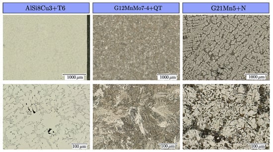
Figure 1.
Overview of microstructure for the investigated materials AlSi8Cu3+T6, G12MnMo7-4+QT and G21Mn5+N.
A dedicated casting geometry was used for the material G21Mn5+N and G12MnMo7-4+QT to ensure a low degree of shrinkage porosity similar to the standard [112]. The chemical composition of the material G21Mn5+N in normalized condition following the standard SEW 685 [113] is given in Table 2, as well as for material G12MnMo7-4+QT according to the standard SEW 520 [114].

Table 2.
Chemical composition in weight percent of the investigated cast steel alloys G12MnMo7-4 and G21Mn5.
Quasi-static tensile tests for the material G21Mn5 revealed a upper yield strength of MPa, a lower yield strength of MPa, an ultimate tensile strength of MPa and an elongation at fracture of more than 50%. An overview of the dendritic, ferrite–pearlite microstructure is given in Figure 1 in the right column. The results of the quasistatic tensile tests of the high-strength cast steel alloy G12MnMo7-4+QT are given in a preceding work of the authors [115]; the corresponding microstructure as a result of the heat treatment is given in the middle column in Figure 1. The metallographic specimens of the cast steel alloys were grinded and polished, followed by etching with with 3% Nital. After the casting process, all cast parts were pre cut using water jet cutting and finally turned by a CNC machine. The final post-processing of the specimen surfaces, e.g., either manually polished or vibratory finished, is applied as final manufacturing step for all fatigue test samples.
2.1. Vibratory Finishing
It is well known that fatigue specimens have to be polished after the CNC-turning process to comply with the specifications of the standard [116,117]. This process is typically carried out manually, but in order to reduce the human influence for highly reproducible surface properties, vibratory finishing appears to be a useful alternative. In addition, electrochemical polishing is an alternative to manual polishing, but requires additional etching equipment and high-current power sources [38]. Whereas polishing primarily targets a reduction of the surface roughness, vibratory finishing offers as side effect a modification of the surface layer regarding residual stress state and hardness distribution, as introduced in Section 1.
A trough vibrator AVAtec® TV 60 (Avatec Gmbh, Sindelfingen, Germany) was used to obtain a defined residual stress state by vibratory finishing. Therefore, different abrasive ceramic and plastic media were used in three subsequent treatment steps (strong grinding, smoothing and polishing). Additionally, a corrosion-preventing compound is necessary to absorb the abrasion of grinding media and workpieces. The specimens were grinded for several hours in the oscillating bowl for each abrasive media. Figure 2 illustrates the obtained surface quality for the polished and vibratory finished condition of each series. Roughness parameters were evaluated with a Mahr® MarSurf VD140 (Mahr Austria GmbH, Vienna, Austria). The arithmetic mean roughness value is µm for the polished (POL) specimens and µm for the vibratory finished (VF) ones, and the total height of the roughness profile is µm for polished and µm for vibratory finished specimens. Due to this quite high surface quality and the low difference of the roughness values, the effect of roughness on fatigue strength was purposely not taken into account in this study. For further sample designation, polished specimens are labelled with the suffix POL and vibratory finished ones with the suffix VF.
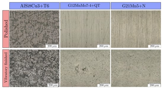
Figure 2.
Comparison of vibratory finished and polished surface for the investigated materials AlSi8Cu3+T6, G12MnMo7-4+QT and G21Mn5+N.
2.2. High Cycle Fatigue Tests (HCF)
The long life fatigue strength for the investigated specimen series has been determined by uniaxial fatigue testing at room temperature following the standard [118,119]. The force-controlled high-cycle fatigue tests are conducted on a RUMUL® Testonic 150 kN (Russenberger Prüfmaschinen AG, Neuhausen am Rheinfall, Switzerland) resonance test rig for the steel specimens and a RUMUL® Microtron 20 kN (Russenberger Prüfmaschinen AG, Neuhausen am Rheinfall, Switzerland) for the aluminium specimens, imposing a global nominal load ratio of . Figure 3a,b depict the specimen geometries used for high cycle fatigue (HCF) testing, which are manufactured from bulk material. The blue marked test sections in Figure 3 were finished with the respective surface treatment, either manually polished or vibratory finished. Each test terminated with the final rupture of the specimen, respectively a certain drop in frequency, or if the run-out number of cycles is achieved. In absence of any damage, in terms of observable surface crack initiation, the run-outs were subsequently retested at high stress levels in the finite life region of the S/N-curve to study the fracture initiating defects for all fatigue samples. Table 3 gives an overview of the high cycle fatigue tests with the related manufacturing and post-treatment coding. It should be mentioned that a part of these summarized results was obtained in preceding work by the authors [115,120,121].
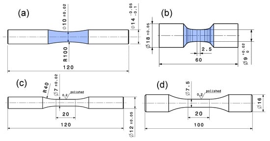
Figure 3.
Specimen geometries for fatigue testing: (a) HCF steel alloys; (b) HCF aluminium alloy; (c) LCF steel alloys; (d) LCF aluminium alloy. All dimensions are in mm.

Table 3.
Overview of the fatigue tests performed on polished and vibratory finished samples for the three investigated materials.
2.3. Low Cycle Fatigue Tests (LCF)
Low cycle fatigue experiments were conducted for the investigated cast materials to determine the elastic–plastic behaviour. The specimens were manufactured following the standard [116,122] featuring only a polished surface condition; see Figure 3c for steel alloys and Figure 3d for aluminium alloy. A servo-hydraulic test rig was used for the strain-controlled fatigue tests utilizing an extensometer for strain measurement. The specimens are tested at a triangular loading sequence featuring a constant strain rate of 1% per second at an alternate strain ratio of .
2.4. Residual Stress Measurements
Polished and vibratory finished specimens of both steel series were subjected to residual stress measurements conducted with a X-RAYBOT from MRX-RAYS® (MRX-RAYS, Brumath, France). This portable X-ray diffractometer was equipped with a 2 mm collimator in accordance with the standard DIN EN 15305 [123], limiting the radius of the irradiated area to the half radius of the surface curvature. The aluminium series were measured with a Seifert XRD Charon SXL (XRD Eigenmann GmbH, Schnaittach, Germany) by Materials Center Leoben Forschung GmbH with a 0.3 mm collimator. Cr-K radiation was used for all series with a wavelength of Å and a -mounting measurement setup following the standard [124]. Furthermore, the applied measurement procedure is in accordance with the standard ASTM E2860-12 [125]. A V-foil is placed in the secondary optical path to filter the Cr-radiation. The X-ray tube is operating at 20 kV and 1 mA and tilts in a range of ±40° in axial specimen direction (-angle). A total number of 17 increments with an exposure time of 60 s each point is used. For the residual stress determination, the diffraction peaks from Al-alpha 311 and Fe-alpha 211 were used and the detected peak shape is fitted by means of a Pseudo-Voight function. The stress evaluation is performed based on the method and elliptical fitting of the data points at a confidence level of 90% is applied. All residual stresses (surface and gradient in depth) were measured along the specimen axis, which represents the loading direction, at selected samples of each material batch.
To carefully remove small layers from the surface a Struers® LectroPol-5 (Struers GmbH, Willich, Germany) was used for electrolytic polishing, exemplarily depicted as polished notch at the specimen surface in Figure 4. A 3D-printed, flow-optimized fluid directing mask characterised by a 0.5 circular area was used at a voltage of 36 V for polishing in the test-cross section of the specimen. The electrolytic solution A2 of Struers is used at a temperature of 5 °C up to 10 °C to perform a constant material removal rate. The electrochemical erosion time was set for each increment individually, guaranteeing that the target depth was reached for subsequent residual stress measurements. The depth profile was measured by a Mahr® MarSurf VD140 (Mahr Austria GmbH, Vienna, Austria) using the contour measuring unit, yielding a depth profile as depicted in Figure 4.
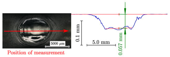
Figure 4.
Electrolytic polished surface on a steel specimen (left) and corresponding cross-section (right). The red arrow represents the direction of measurement for the blue profile.
2.5. Fracture Analysis and Computed Tomography
Subsequently to the fatigue testing, the ruptured specimens’ fracture surfaces were analysed utilizing a digital optical microscope (DOM) from KEYENCE® VHX-5000 (Keyence Corporation, Osaka, Japan) for macroscopic inspection. Local analysis of the fracture initiating defect was carried out by means of a ZEISS EVO 15 (Carl Zeiss AG, Oberkochen, Germany) scanning electron microscope (SEM), allowing a further magnified inspection of fracture origin and measurement of defects’ sizes. Non-destructive testing by means of computed tomography (CT) was realized by a Phoenix/X-ray Nanotom 180 (GE inspection technologies, Lewistown, PA, USA) using a voxel-size of just 4.5 m for series AlSi8Cu3-A-T6 and 5.5 m for AlSi8Cu3-B-T6.
2.6. Hardness Measurement
Macro hardness was measured by a ZWICK® ZHU 2.5 (ZwickRoell GmbH & Co. KG, Ulm, Germany) test rig using a Vickers indenter. The applied testing parameters correspond to HV1 testing, according to standard ASTM E384 [126], and were used for surface hardness measurements to differentiate between polished and vibratory finished condition. Furthermore, nano-indentation measurements were conducted at the Department of Materials Science (Montanuniversität Leoben, Leoben, Austria) for selected specimens to determine a work hardening of the surface layer by post treatment. Therefore, a Keysight Nanoindenter G200 (Keysight Technologies, Santa Rosa, CA, USA) testing unit utilizing a Berkovich indenter at a constant strain rate of 0.05 was used. The indentation depth was 150 nm for cross section in the surface layer and 2500 nm for the cross section in the bulk material.
2.7. Crack Propagation Testing
To build up the Kitagawa–Takahashi diagram and its fracture mechanical extensions, detailed information about the crack growth behaviour is necessary. Long-crack growth threshold stress intensity factors were determined for load ratios from up to to obtain the Newman curve [103]. The short crack threshold values were determined at high load–stress ratios to minimize closure effects, as presented in in [127,128]. Single edge notched bending specimens were utilized. Their geometry is illustrated in Figure 5.

Figure 5.
SENB-specimen geometry for fatigue crack growth testing. All dimensions are in mm.
After extracting the specimens from the bulk material using a CNC-milling machine, an initial notch featuring a depth of 4 mm and a width of 0.35 mm was manufactured using wire cut discharge machining (EDM). To facilitate the measurement of the initial notch geometry by the DOM, the sides of the sample were grinded and polished up to 1 m using diamond suspension. A sharp mechanical notch, which is necessary for subsequent compression pre-cracking, was produced by razor-blade polishing utilizing a 6 m diamond paste. Compressive pre-cracking [129,130] was conducted on a SincoTec® Power Swing MOT100kN (SincoTec Test Systems GmbH, Clausthal-Zellerfeld, Germany) resonance test rig at a stress ratio of . To determine the cyclic R-curve behaviour, the stepwise rising load amplitude crack growth test according to Tabernig et al. [131] was applied. Crack propagation experiments were conducted using a RUMUL® Cracktronic (Russenberger Prüfmaschinen AG, Neuhausen am Rheinfall, Switzerland) resonance test rig. The constant amplitude loading was started at and stepwise increased to capture the cyclic R-curve until long-crack propagation occurred. The crack length was measured by the direct current potential voltage drop (DCPD) method incorporating a temperature coefficient to compensate the effect of ambient temperature change.
3. Results
3.1. High Cycle Fatigue Strength
The statistical evaluation of the fatigue data in the finite life region was conducted according to the standard [132]. In the long-life fatigue regime, the fatigue strength was estimated at a probability of survival of applying the transformation [133]. The slope in the long-life region was estimated as function of the slope in the finite life region , as proven applicable in [19,134]. Some of the fatigue test results can be found in previous publications [120,135], but additional data points were included to extend the experimental database and improve statistical evaluation.
Figure 6 displays the fatigue data of the material AlSi8Cu3 in heat treatment T6 (a) and HIP+T6 (b) condition. Each test series of the Al-specimens is opposed for the two different surface conditions; see suffix POL and VF. For the HIP+T6 treated series, representing the porosity free base material strength, the long life fatigue strength of the vibratory finished samples (AlSi8Cu3-A-HIP+T6-VF) was increased by 10.2% compared to the polished ones (AlSi8Cu3-A-HIP+T6-POL); see S-N curves in Figure 6b. The slopes in the finite life region for both surface states are quit similar, but the scatter index of the vibratory finished samples is significantly reduced compared to the polished state; see summary in Table 4.
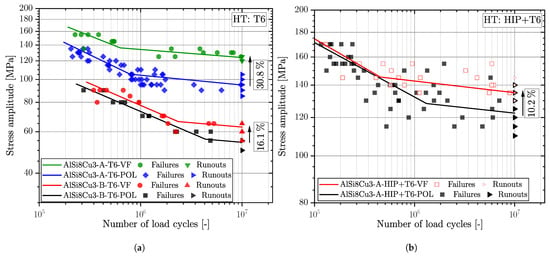
Figure 6.
S-N-curves for (a) T6 heat treated and (b) HIP+T6 heat treated cast material AlSi8Cu3 in vibratory finished and polished surface condition for load–stress ratio .

Table 4.
Fatigue strength results for AlSi8Cu3 cast material.
Series AlSi8Cu3-A-T6 revealed a improvement of the mean long life fatigue strength due to vibratory finishing of 30.8%; see blue and green marked data in Figure 6a. This position revealed a decrease in the scatter index in the long life region too, as well as the slope in the finite life region keeps similar. Concerning the fatigue data for the coarse microstructure, represented by series AlSi8Cu3-B-T6, the slope for polished is along the slope for vibratory finished surface, but the scatter index is increased for the vibratory finished fatigue data. Apart the high porosity of these samples the comparable low number of tested fatigue specimens might be a reason for the slightly increased fatigue scatter index. An increase in mean fatigue strength was additionally achieved by 16.1% by vibratory finishing.
Figure 7 depicts the fatigue data for the cast steel series G21Mn5+N and G12MnMo7-4+QT for the polished and vibratory finished surface conditions. It can be clearly seen that the increase in fatigue strength is somewhat reduced compared to the aluminium alloy. One reason might be due to the increased strength of the material and therefore a reduced plastic deformation in the surface layer. The low-strength cast steel alloy revealed an increase in by 7.1%, and the high-strength cast steel alloy just 2.2%. This confirms the previous assumption that the applied vibratory finishing process is no longer capable of increasing the fatigue strength significantly. It should be noted that the vibratory finishing treatment parameters and applied ceramics are identical for both cast steel materials; see Section 2. Both cast steel series revealed quite similar slopes in the finite life region.
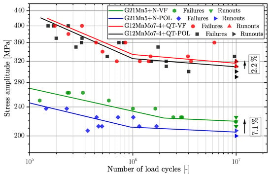
Figure 7.
Fatigue test results of series G12MnMo7-4+QT and G21Mn5+N in vibratory finished and polished surface condition for load–stress ratio .
Series G12MnMo7-4+QT exhibited a significant reduction of the fatigue scatter index, although series G21Mn5+N remains almost unaffected; see summarized fatigue data in Table 5. The aim of this experimental work was to build-up a fatigue test database on the effect of vibratory finishing versus manual polished surface conditions for cast aluminium and cast steel alloys. This database is further on used as experimental reference to extend the layer-based fatigue assessment model towards effective stress ratio effects.

Table 5.
Comparison of fatigue results for cast steel series G21Mn5+Nand G12MnMo7-4+QT in polished a vibratory finished condition.
3.2. Short and Long Crack Propagation
In order to facilitate a fracture-mechanical approach for fatigue assessment, short and long crack growth data are necessary for all investigated cast alloys. All crack growth data were evaluated at a probability of occurrence of . Short and long crack growth behaviour of the aluminium series AlSi8Cu3-A and AlSi8Cu3-B, including detailed analysis of the microstructural relationship as well as a generalized dataset, is already reported in [93].
Moreover, the crack growth behaviour of series G21Mn5+N was analyzed in detail by the authors in [136]. It should be mentioned, that additional experiments were conducted to extend previous studies for statistical improvement. The crack closure factor representing the generalized R-curves according to Kolitsch et al. [137] is summarized in Figure 8b for all investigated alloys. Crack growth data of series G12MnMo7-4+QT have been extended for different stress ratios within this work; compare to Figure 8a as reference. A summary of the R-curve data for this high strength cast alloy is given in Table 6. The long crack growth threshold values are given in Table 7.
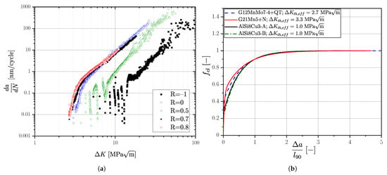
Figure 8.
Crack growth data: (a) Short and long crack growth curves for series G12MnMo7-4+QT and (b) Generalized R-curves for all investigated cast alloy series.

Table 6.
Generalized R-curve parameters for cast steel alloy G12MnMo7-4+QT for .

Table 7.
Long Crack growth threshold values of series G12MnMo7-4+QT for .
3.3. Cyclic Elastic-Plastic Material Behaviour
The statistical evaluation of the experimental results was conducted according the standard [116,122], defining the number of cycles to failure as a ten-percent decrease in the stabilized hysteresis. Subsequent, a strain-based low-cycle-fatigue study is conducted for all materials and evaluated according to Manson [138], Coffin [139] and Basquin [140] using the elastic–plastic strains at . The evaluated curves are depicted in Figure 9 for the material AlSi8Cu3 as well as in Figure 10 for the steel alloys.
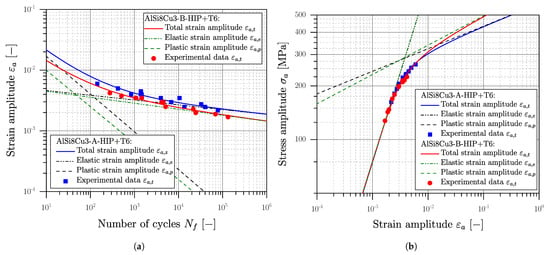
Figure 9.
Low cycle fatigue results of AlSi8Cu3 cast alloy for (a) Manson–Coffin curve and (b) Stabilized cyclic stress–strain behaviour.
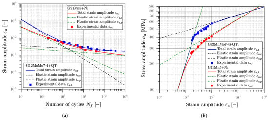
Figure 10.
Low cycle fatigue results of cast steel alloys for (a) Manson–Coffin curve and (b) Stabilized cyclic stress–strain behaviour.
The total strain amplitude of the Manson–Coffin curve can be calculated as superposition of the elastic and plastic portion, represented by Equation (12) [138,139,140]. The elastic portion of the Manson–Coffin curve is given by the fatigue strength coefficient , the Young’s modulus and the fatigue strength exponent b of Basquin. For the plastic part in Equation (12), a ductility coefficient and the ductility exponent c are used [139,140,141].
The stabilized cyclic stress–strain curve, depicted in Figure 9b and Figure 10b, was evaluated according to the Ramberg–Osgood formulation [142], given in Equation (13).
The cyclic hardening coefficient is calculated following Equation (14) utilizing the parameters of the Manson–Coffin curve as well as the cyclic strain hardening exponent , as given in Equation (16) [143,144].
Low cycle fatigue experiments were conducted for the HIP+T6 treated aluminium series AlSi8Cu3-A-HIP+T6 and AlSi8Cu3-B-HIP+T6 due to the quite brittle behaviour of the defect-afflicted T6 series. The cyclic stress–strain curves in Figure 9b are similar; the low cycle fatigue strength of position B is somewhat reduced due to the coarser microstructure; see Figure 9a. Comparing the 0.01% yield stress of MPa of position A, and respectively MPa for position B, a small fraction of cyclic hardening can be assumed. For both cast steel series cyclic softening can be perceived clearly, comparing the initial yield strength of and ; see Figure 10b. A summary of the elastic–plastic fatigue experiments is given in Table 8.

Table 8.
Summary of basic elastic–plastic parameters of the investigated cast alloys.
To numerically simulate the redistribution of the residual stress state in the surface layer due to local work hardening, a proper cyclic plasticity material model has to be evaluated from the established experimental database. The superposition of notches and residual stresses in the surface layer enforces the simulation of local mean-stress relaxation by cyclic loading. The parameters of the combined hardening simulation model are explained in Section 1; see Equations (2)–(6). Two back stresses are considered for the non-linear kinematic part of the combined hardening model; see summary of the determined parameters in Table 9.

Table 9.
Non-linear combined hardening models for the investigated cast materials.
A non-linear finite element analysis was carried out using Simulia Abaqus® CAE/2022 to validate the combined hardening model against experimental specimen test data. Therefore, single element tests were conducted to evaluate the stabilized hysteresis loop at selected strain amplitudes using axisymmetric elements of type CAX4R. Figure 11 depicts experimental and simulated stabilized hysteresis loops for all investigated series.
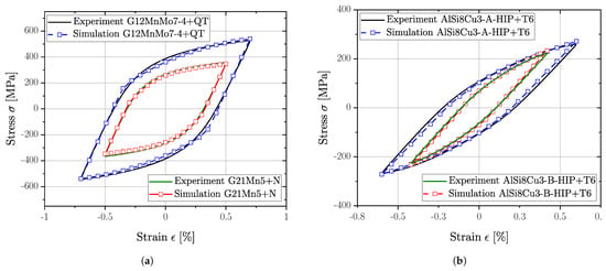
Figure 11.
Validation of non-linear combined hardening models at stabilized condition for selected LCF-tests: (a) Cast steel alloys and (b) Cast aluminium alloys.
3.4. Fractography and Statistics of Extremes
All fracture surfaces of the fatigue tested samples were analysed with regard to crack initiation site and failure mechanism. Selected fracture surfaces of tested samples are depicted in Figure 12, where the red line highlights the crack initiation spot. Specimen series AlSi8Cu3-A-HP+T6 exhibited different failure mechanisms like slip bands, oxide films, inclusions or small surface pits for both surface states. All these inhomogeneities were located near, or at, the specimen surface. Figure 12a displays a slip surface interacting with small oxide films, which can be identified as dark areas in the blue-framed sub-figure. A fracture surface with a crack initiating from a surface pit is depicted in Figure 12b. Porosity induced crack initiation is identified as the main failure mechanism for aluminium specimen series Alsi8Cu3-A-T6 and Alsi8Cu3-B-T6 for both surface finishing treatments; see Figure 12c,d, where position A revealed a mean defect size of and position B . The distance of fracture initiating defects from the surface for vibratory finished samples is slightly increased compared to polished ones. One reason might be the compressive residual stress state in the surface layer [145], shifting the crack initiation site below the surface until an increasing effective load–stress ratio is achieved again.
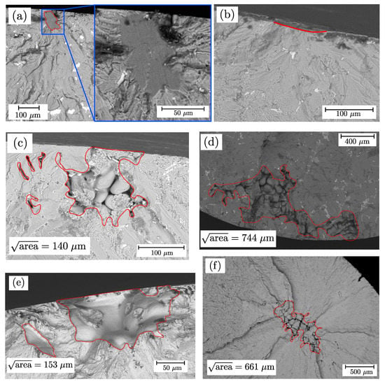
Figure 12.
Main fracture initiating defects of the investigated specimen series for polished and vibratory finished surface condition: (a) Slip band and (b) Surface initiation; (c) Shrinkage AlSi8Cu3-A and (d) Shrinkage AlSi8Cu3-B; (e) Shrinkage G12MnMo7-4+QT and (f) Bulk shrinkage G21Mn5+N.
Figure 12e depicts porosity as the main failure mechanism of series G12MnMo7-4+QT for polished and vibratory finished surface, resulting a mean imperfection size of . Almost all fracture initiating defects are superficial. Regarding series G21Mn5+N, a larger fraction are bulk volume defects, as depicted in Figure 12f. The statistical mean of the projected imperfection size is . The evaluation of the projected area of the defects as well as the distance from the surface were measured using Fiji [146] as image processing tool. A spline was drawn manually around the contour of the defect, leading to smaller but more precisely defined defect sizes compared to Murakami’s convex hull approach. Moreover, a direct comparison of the projected area from computed tomography and fractography is therefore possible. Interacting defects were defined according to the proposal of Åman et al. [147], that states if the distance between two defects is less than the size of the smaller defect, both defects have to be considered as interacting. In this case, the sum of the projected was taken into account.
Statistics of extreme were applied to study the distribution of fracture initiating defects, as introduced in Section 1. Regression analysis using Matlab® 2020b parametrized the generalized extreme value (GEV) distribution functions for each series. The general distribution function is given in Equation (10). The parameters of the distribution function, namely, location , scale and shape parameter were determined using the maximum likelihood estimation [148], followed by a Kolmogorov–Smirnov (KS) test at a significance level of 5% to proof the goodness of fit for the evaluated distribution [149]. Figure 13 depicts the cumulative GEV distributions for AlSi8Cu3-A-T6 and AlSi8Cu3-B-T6 series, both for polished and vibratory finished condition. The maximum sized defects of the vibratory finished condition are slightly increased compared to polished ones, but the mean value is quite similar for both specimen series. Series AlSi8Cu3-A-T6 results for the polished and for the vibratory finished state and series AlSi8Cu3-B-T6 for polished and for vibratory finished samples. Since the scatter bands of both series are overlapping for each surface state, a common GEV was evaluated summarizing the defects of polished and vibratory finished surface state for each specimen series; see dashed orange line in Figure 13 for series AlSi8Cu3-A-T6 and dashed purple line for series AlSi8Cu3-B-T6. Moreover, the basic defect distribution for polished and vibratory finished state within the whole sample is the same, because the difference is caused by the residual stress field in the surface layer.
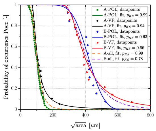
Figure 13.
Defect distributions for AlSi8Cu3-A+T6 and AlSi8Cu3-B+T6.
A summary of the evaluated distribution parameters for all defects for polished and vibratory finished state as well as the related projected for all fracture initiating defects is given in Table 10. Fracture surfaces of steel samples were statistically analysed yielding the distributions plotted in Figure 14. Series G12MnMo7-4+QT reveals quite similar GEVs for the polished and vibratory finished surface; see red marked data for vibratory finished () and blue marked for polished () data in Figure 14. In addition, a combined GEV distribution for polished and vibratory finished was evaluated as well; see dashed purple line in Figure 14 and data summary in Table 10. Series G21Mn5+N reveals a comparably large scatter band of the assessed GEV for polished () and vibratory finished () surface condition. Concluding, a common GEV was evaluated as well for this cast material; see dashed orange line in Figure 14. It should be mentioned that the evaluated GEV distributions are based on measurement of the projected imperfection area of each fatigue tested specimen.

Table 10.
GEV distribution parameters of the investigated fracture surfaces.
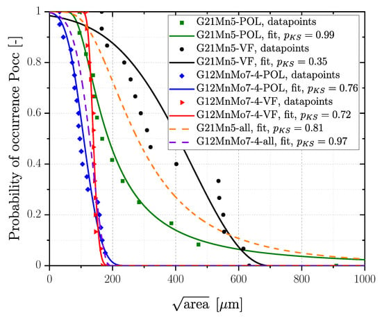
Figure 14.
Defect distributions of G12MnMo7-4+QT and G21Mn5+N.
3.5. Computed Tomography
Computed tomography investigations were conducted only for the aluminium series, applying a threshold-based image post processing of the raw data, as detailed in a previous study of the authors [94]. A clustering of interacting porosity networks was incorporated following the proposal of Åman et al. [147]. Subsequently, the projected area was evaluated perpendicular to the load direction. As mentioned in the previous section, the region of failure initiation for cast aluminium alloys ranges from superficial defects up to bulk defects with a minimum distance to the surface of more than 500 m. Thus, the computed tomography raw data have been evaluated for different layers. The size of the layer was set in accordance to the position of the majority of fracture-initiating pores. Hence, a layer starting from the surface up to a distance of 100 m was selected for the polished specimens of series AlSi8Cu3-A-T6 and 250 m for the vibratory finished ones based on the analysis of the fracture surfaces. Series AlSi8Cu3-B-T6 revealed a size for the surface layer of 400 m for the polished surface and 500 m in the case of a vibratory finished state.
The distribution of defects detected by CT using POT has asymptotic properties, thus a generalized Pareto distribution can be fitted to the data. Most of the pores are not critical regarding fatigue resistance, therefore a proper threshold value has to be chosen above which pores considered as fatigue critical. Romano et al. [108] determined the threshold value of CT-data using mean excess plots for additive manufactured parts. Mean residual life plots and threshold stability plots for the generalized Pareto distribution [150] were used to determine an applicable threshold set value for the defect size of the CT data of the cast aluminium parts [151,152]. Once a proper threshold is calculated, the mean residual life over the selected threshold value becomes linear [108]. Mean residual life plots and threshold choice plots revealed a threshold value of about 90 m for series AlSi8Cu3-A-T6 and 350 m for series AlSi8Cu3-B-T6, resulting in the GEV distributions depicted in Figure 15. In addition, a comparison of the CT-data and fractography for the fatigue critical layers was performed, leading to a sound accordance of the distributions; see Figure 15a.
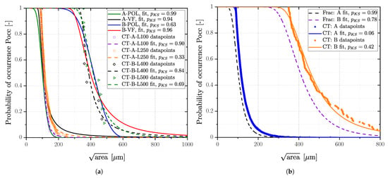
Figure 15.
Comparison of fractography and computed tomography for AlSi8Cu3-A+T6 and AlSi8Cu3-B+T6: (a) Inspected layers for predominant region of failure in case of POL and VF samples and (b) Mean fractographic distribution compared to computed tomography.
For applications in practice, the size of the fatigue critical layer is not known in advance. One can choose the highly stressed volume (HSV) for CT scan as well, but the statistical size effect has to be considered accordingly [94]. Incorporating all defects of the specimens’ cross section results in distributions as depicted in Figure 15b. The mean values of the GEV for both Al-series as well as the associated parameters are given in Table 11. The distributions are shifted slightly to larger defects due to the effect of HSV.

Table 11.
Distribution parameters of shrinkage porosity over the entire specimen cross section analysed by CT.
3.6. Residual Stress Measurements
Residual stresses were measured for all investigated specimen series except AlSi8Cu3-B-T6 in several positions in the surface layer, depicted in Figure 16a,b. The residual stress state was measured in the test cross-section of the specimen along the loading direction, representing the z-axis in Figure 16c. It is clearly shown in Table 12 that machined and vibratory finished specimens are characterised by a compressive residual stress state on the surface, but at a certain distance from the surface, the residual stress state undergoes a rapid change. Figure 16a depicts the magnitude of the measured residual stress state in the surface layer for the aluminium series, whereas Figure 16b illustrates the residual stress profiles for the steel series.
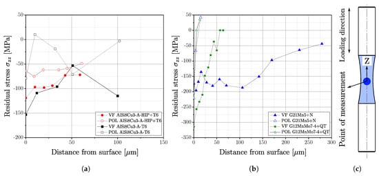
Figure 16.
Residual stress measurements in the surface layer of polished (POL) and vibratory finished (VF) specimens: (a) Magnitude of residual stresses in z-direction for aluminium series, (b) Magnitude of residual stresses in z-direction for steel series, (c) Position of measurement for selected specimen geometry.

Table 12.
Measured initial surface residual stress for polished and vibratory finished specimens.
Polished specimens of the cast steel series revealed a strong gradient towards tensile values since the initiated compressive residual stress state at the surface changes between 10 m and 15 m to tensile; see Figure 16b. However, apart from the initial surface condition, the course of residual stresses is quite similar for the polished steel series. In contrast, the vibratory finished condition revealed different distributions of the stress state; see Figure 16b. Whereas series G12MnMo7-4+QT still possess a large gradient with transition into tensile stress state at a depth of about 60 m, series G21Mn5+N exhibits a decreased gradient and therefore compressive residual stresses up to a depth of 300 m. One reason might be the comparably high strength and increased hardness of the quenched and tempered series G12MnMo7-4. Thus, reducing the impact of the ceramic particles of vibratory finishing process featuring small plastic deformations at the surface layer, whereas the more ductile series G21Mn5+N is affected a somewhat due to its lower yield limit.
The aluminium series AlSi8Cu3-A-T6 indicates the same behaviour as the steel parts; the compressive layer of the polished surface is quite small, and the gradient of the vibratory finished surface is decreased; see Figure 16a. In contrast, series AlSi8Cu3-A-HIP+T6 features a low gradient for the polished state as well. One reason for this still-decreased gradient of polished surface condition might be a pre-existing residual stress state resulting from the HIP process, apparent when comparing series AlSi8Cu3-A-T6-POL and AlSi8Cu3-A-HIP+T6-POL in Figure 16a.
3.7. Surface Layer Hardness
Vickers hardness measurements were conducted at the investigated specimens’ surfaces. Comparing the ratio of the smooth roughness profile for both surface conditions to the indentation depth, the influence of the surface profile on hardness can be neglected. Figure 17 depicts the probability density functions (PDF) of the Vickers Hardness (HV1) and the corresponding mean value in the framed box as well. Except for series AlSi8Cu3-B-T6, all investigated samples revealed an increase in surface hardness after vibratory finishing. Depending on the strength, respectively hardness of the material, enhancement ranges between 5.7% for the high strength cast steel alloy up to 11.5% for the aluminium alloy of position A. The lower strength cast steel alloy reveals an increase of 9.4%. Only series AlSi8Cu3-B-T6 revealed no significant change of hardness, but the scatter index of the polished specimens is somewhat increased. One reason might be coarse microstructure and high degree of porosity of these samples series implying a reduced plastic deformability.
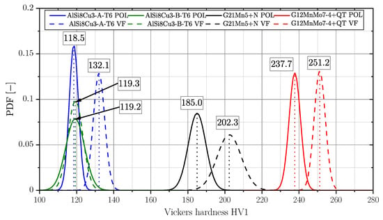
Figure 17.
Surface hardness HV1 of series AlSi8Cu3-A-T6, AlSi8Cu3-B-T6, G21Mn5+N and G12MnMo7-4+QT for polished and vibratory finished surface. Boxed values represent the mean values of the normal distributions.
In addition, nanoindentation experiments were carried out in the cross section of the surface layer in order to obtain information about the hardness gradient by polishing or vibratory finishing. It should be mentioned that the indenter tips of Vickers for macrohardness and Berkovich for nanoindentation are different and the hardness results are therefore not directly comparable. But the main focus is laid on the course of the hardness in the surface layer, dependent on the material series and surface treatment condition. Figure 18 depicts the obtained results for series AlSi8Cu3-A-T6 and G21Mn5+N. A grid of indentation points was positioned at the surface layer, exemplary shown in the subfigures of the plots in Figure 18. In case of series AlSi8Cu3-A-T6, a slight increase in hardness can be noticed comparing the red and black datapoints at the surface position in Figure 18a. In contrast, the cast steel alloy G21Mn5+N reveals no recognizable change of hardness in the surface layer; see Figure 18b.
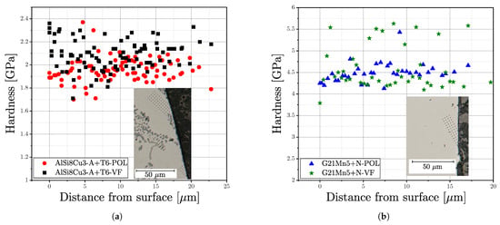
Figure 18.
Nanoindentation measurements of series (a) AlSi8Cu3-A-T6 and (b) G21Mn5+N.
However, the intensity of the vibratory finishing process is quite small for the used ceramic and plastic process media in case of steel samples, in contrast to literature data, where increased hardness values could be observed using special finishing media [54,55]. The scatter of the datapoints can be justified by the effect of the local microstructure within the comparably low indentation depth of only 150 nm.
4. Cyclic Stability of Residual Stresses
It was shown in Section 3 that the fatigue behaviour of the investigated materials changes quite significantly towards increased fatigue performance by vibratory finishing, with exception of the high strength cast steel alloy G12MnMo7-4+QT, lacking a pronounced increase in similar strength. Manufacturing process based defects such as shrinkage porosity for example are playing a major role in terms of fatigue performance; see Section 1. Depending on size, shape and position of inhomogeneities in respect to the surface, varying fatigue strength values can be obtained. In the vicinity of each defect, the residual stress field within the appropriate surface layer may become modified due to cyclic hardening or softening. Sausto et al. [24] proposed to determine the residual stress relaxation using elastic–plastic FE simulations to predict the evolution of the residual stress state in the surface layer for additive manufactured samples with different surface layer treatments. As depicted in the experimental work, the effect of vibratory finishing versus manual polishing depends on the locally applicable residual stress ratio for each material, as the defect distribution itself is not changed by the surface treatment process itself. Thus, the key part of this work focusses on the extension of layer-based fatigue assessment tool, as previously introduced for cast aluminium alloys [94], towards consideration of the effective residual stress state for each extremal defect. This section deals with the predicted stability of the residual stress state in the surface layer during fatigue loading by simulation.
4.1. Approximation of Residual Stress Profile
In order to perform a numerical simulation on residual stress relaxation, a continuous stress profile into the specimen depth is essential. For fatigue analysis, only the first material layers are of particular importance. Therefore, the residual stresses of the tested specimens were measured to a depth of approximately in the size of the El-Haddad length . These residual stresses must be self-equilibrated within the considered part. According to the findings of Smith et al. [153], the residual stress field within a cylindrical body must satisfy the equilibrium relationships stated in Equation (16).
represents the maximum radius of the cylindrical specimen cross section and is the axial stress function along the radius r. The initial function of was evaluated based on the experimental measurements in the surface layer; values of the residual stresses in the material depth were calculated in an iterative process to fulfil Equation (16).
Figure 19 exemplary depicts the approximated residual stress profile for one aluminium series, (a) for polished surface and (b) for vibratory finished surface and Figure 20 for one cast steel alloy. The measurements for both surface post-treatment states revealed a high scatter of the derived residual stresses; see green line and related error bars at the measurement points. This scattering of residual stress data points can be attributed to the effect of local microstructure. An estimate of the approximation function was made as multiparametric exponential function. In the following step, the stress values of the approximation function were implemented in the FE-model as initial stress state, followed by an subsequent equilibrium step. The respective stress distribution in equilibrium state of the FE simulation is given in the sub plots and the blue lines as well.
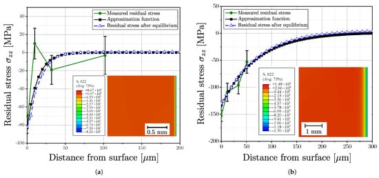
Figure 19.
Approximated residual stress profile of series AlSi8Cu3-A-T6 and profile after equilibrium step in FE simulation for (a) Polished surface and (b) Vibratory finished surface.
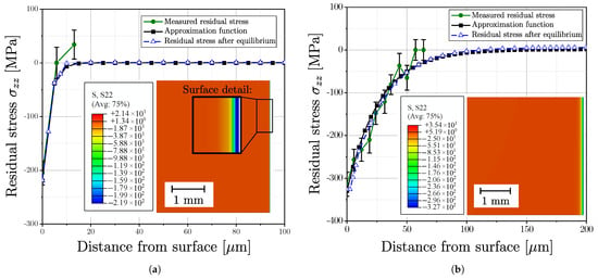
Figure 20.
Approximated residual stress profile of series G12MnMo7-4+QT and profile after equilibrium step in FE simulation for (a) Polished surface and (b) Vibratory finished surface.
4.2. Numerical Analyses
An axisymmetric model of the gauge section was used to investigate the cyclic evolution of the residual stresses inside the surface layer to reduce computational effort of the elastic–plastic FE-simulations in Abaqus CAE/2022. A user defined Python script was developed to set-up a proper axisymmetric model and subsequent postprocessing. A cyclic load function was defined for the applied surface until a stable stress–strain hysteresis is reached. The set-values for the combined hardening material model were taken from Table 9. Linear axisymmetric elements of type CAX4R were adopted to mesh the model. A very high mesh refinement was necessary to achieve numerical convergence concerning the steep stress gradient in the surface layer, especially for the polished samples. Hence, an element size starting with 2.5 m was applied for local mesh seed. Thus, up to 18,000 axisymmetric elements were necessary to properly simulate the residual stress gradient in the surface layer; see red bounded box in Figure 21. XASYMM and ZASYMM boundary conditions were applied, depicted in Figure 21.
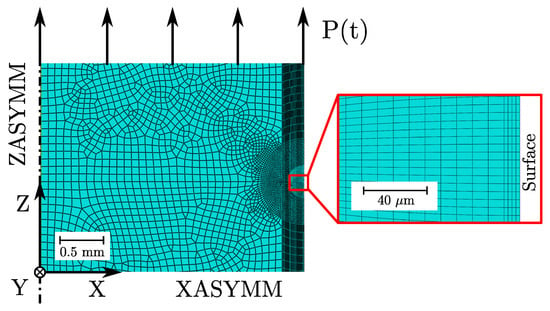
Figure 21.
Simulation set-up to determine the stable effective load–stress ratio in the surface layer.
Within post processing, stresses and strains were evaluated on user defined stress paths as a function of time or load cycles respectively and radial position in the specimen cross section. Figure 22a depicts the effective load stress for a vibratory finished sample on the surface , in a distance of from the surface , a distance of labelled as and the applied load stress in the center of the specimen . The effective stress state over the specimens’ radius R as well as the corresponding effective load–stress ratio are plotted in Figure 22b for the vibratory finished surface state. Similarly, Figure 22c,d depict the results for the polished surface condition of series AlSi8Cu3-A-T6. Calculation of the effective load–stress ratio is conducted invoking Equation (17) for three different depth values in Table 13.
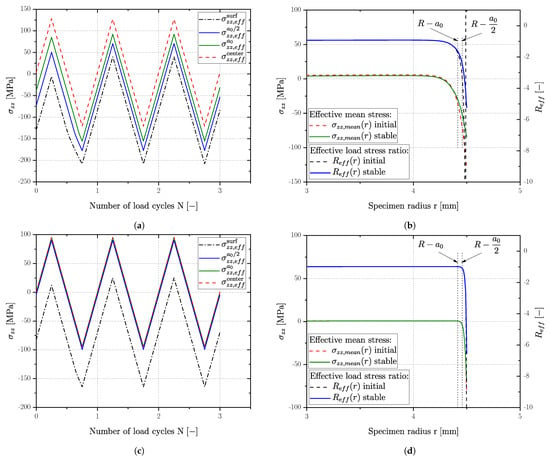
Figure 22.
Simulation of cyclic residual stress behaviour in the surface layer, exemplifying effective mean stress course and stress ratio in AlSi8Cu3-A-T6 samples as (a) Stress history by VF (b) Effective stress ratio by VF (c) Stress history by POL (d) Effective stress ratio by POL.

Table 13.
Stabilized effective load–stress ratio in the specimen cross section determined by elastic–plastic FE simulations.
It is clearly evident in Figure 22a,b that plastic deformation in the surface layer takes place mostly in the first stress-controlled load cycle. Whereas the polished state reveals a plastic deformation only in the first few microns in the surface layer (see stress distribution in Figure 22d) vibratory finished samples revealed a larger zone of plastic influence up to a distance of from the surface.
Table 13 presents a summary of the stabilized effective load–stress ratio of all investigated series in polished and vibratory finished condition. The values are given at the aforementioned distances from the surface (, ) and at the surface. A positive value of the effective load–stress ratio occurs if the residual stress state is somewhat higher than the applied load stress . All specimen series revealed a compressive stable effective load–stress ratio at the surface. In a distance of from the surface, was compressive as well for the vibratory finished samples, whereas the polished samples approach the global applied load–stress ratio, except series AlSi8Cu3-A-HIP+T6 possessing a comparably flat gradient. At a distance of almost all values are set to the global applied load–stress ratio, even though an effect of the shallower residual stress gradient remained.
The applied scheme for modelling the effective stable load–stress ratio of a sample subjected to cyclic loading is given in Figure 23. Step 1a represents the experimental part regarding residual stress measurement in the manufacturing process based surface layer. In parallel, a proper material model must be set-up for work hardening simulation as Step 1b for example by evaluating low cycle fatigue tests. Step 2 represents the conduction of the elastic plastic simulation of the updated residual stress profile in the surface layer. Finally, a stable residual stress state can be estimated along the specimens’ radius, Step 3, resulting the effective load–stress ratio as input parameter for subsequent fatigue assessment as Step 4.
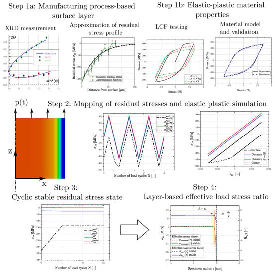
Figure 23.
Schematic description of the process for determining the cyclic stable residual stress profile and effective load–stress ratio, which serve as input parameters for fatigue strength assessment.
4.3. Experimental Validation of Stabilized Hysteresis Loop
Although the validation of the invoked material model was realized by strain controlled single element tests, an experimental validation of the cyclic stable residual stress state on the surface was conducted as well for series G21Mn5+N up to long life fatigue limit. Thereby, the high cycle fatigue test was interrupted at selected numbers of load cycles to measure the surface residual stress state. The applied load stress amplitude is about 200 MPa, ensuring fatigue testing in the long life region.
The course of the residual stress profile in dependency of the load cycle number is given in Figure 24a. It is clearly evident from the experimental results (black dash-dotted line with red scatter of the measurement) that the first cycles are most important regarding residual stress redistribution, achieving the stable residual stress in the first few load cycles. The observed increase in the compressive residual stress state on the surface at cycles my be due to deviation of the measurement set point. But the simulation is still within the measured scatter band. Overall, simulated residual stresses revealed a satisfying compliance to the measured mean values, evident in Figure 24a that the simulation always remains within the scatter band of the measurements. Moreover, a stable residual stress state is accomplished in the simulation within the first load cycle (see Figure 24b) due to plastic deformation during pressure loading.
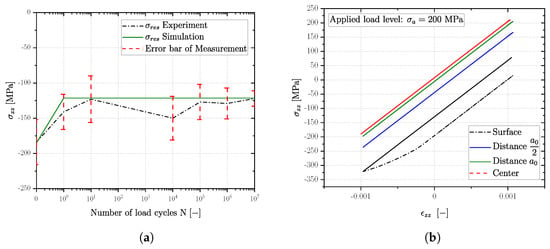
Figure 24.
Validation of residual stress redistribution for series G21Mn5+N with vibratory finishing: (a) Comparison of simulation and experiment and (b) Cyclic stress strain behaviour in selected layers.
5. Fatigue Model and Discussion
This section provides the implementation of the numerically simulated effective stable residual stress ratio into established fatigue models capable for defect tolerant design. The defect distribution is evaluated for each layer, and the obtained extremal defect size links to the fatigue threshold limit as Kitagawa–Takahashi diagram [26]. Otherwise, Murakami’s concept relates the projected extremal defect area of the assessed layer to the fatigue stress limit [21]. As pointed out in the previous section, the effect of effective residual stress ratio, and related change in micro hardness, within the evaluated layer shall be additionally considered to improve these fatigue design concepts further. Without the proper knowledge of the effective stress ratio, one cannot distinguish between manually polished and vibratory finished surface condition. Hence, the extended fatigue models shall be able to incorporate the effect of post surface finishing method properly.
The calculated fatigue limits are compared to the endurance value of the S/N-curves as given in Section 3. Table 4 and Table 5 depict the experimentally obtained long-life fatigue strengths of cast aluminum and cast steel as reference. The evaluated design strength of each series is based on a probability of fifty percent of the imperfection distribution. In case of aluminum alloys, the aggregated distribution of all CT-scanned samples has been utilized, compare to of AlSi8Cu3-A+T6 and AlSi8Cu3-B+T6 in Figure 15 of the highly-stressed volumes. In case of cast steel, the mean occurrence value of the defects is based on the fractographically determined distribution for G21Mn5+N and G12MnMo7-4+QT.
5.1. Kitagawa–Takahashi Diagram
The Kitagawa–Takahashi diagram (KTD) is one of the most widely used fatigue strength models based on fracture mechanics, which considers manufacturing process induced material inhomogeneities. In this work, El-Haddad’s extension et al. [61] and the effect of crack closure mechanisms according to Chapetti [91] are utilized for fatigue strength assessment. The fracture mechanical crack closure integration was already extended regarding defect distribution and layer based fatigue assessment for AlSi-cast parts in [94,135]. It is denoted in this work as R-curve concept; see Equation (18). Figure 25 depicts the KTD in original formulation (solid lines), with the modification by El-Haddad (dotted line) and the R-curve concept (dashed line) for different effective load–stress ratios for cast steel alloys G21Mn5+N and G12MnMo7-4+QT. The illustrated range of the cyclic stable effective load–stress ratio is taken in accordance to the simulation study, results summarized in Table 13, as shown in detail in Section 4, for the respective series and surface state.
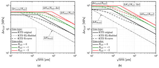
Figure 25.
Schematic representation of the original Kitagawa diagram, as well as its modifications for three different effective load–stress ratios (): (a) G21Mn5+N and (b) G12MnMo7-4+QT.
The upper border represents the fatigue strength of the defect free base material. It can be calculated from the Ramberg–Osgood parameters of the cyclic stable stress strain curve, or experimentally as S/N-curve from defect-free samples. For the aluminium alloy, was obtained from fatigue testing of HIP+T6 treated samples. Thus, the local base material strength for the effective local load–stress ratio can be calculated using the Haigh diagram in accordance with the standard [58]. For both cast steel alloys, the base material strength was estimated using the Ramberg–Osgood parameters according Equation (9), as no defect free samples were available for fatigue testing. The effective load–stress ratio was taken into account in the same way as for the aluminium alloy.
The long crack threshold value as function of the effective load–stress ratio can be determined from the Newman curve [103] for the respective material; see Figure 26a and Equation (20), representing the right border of the KT-diagram. The transition between crack threshold and base material strength is characterized by the build up of extrinsic shielding mechanisms, which can be represented by the cyclic R-curve, as given in Figure 26b for aluminium alloy AlSi8Cu3-AB, in Figure 26c for cast steel G21Mn5+N, and in Figure 26d for cast steel G12MnMo7-4+QT. Depending on the effective load–stress ratio , the local crack threshold affected by build up of closure mechanisms is a function of the crack extension, as proposed by Maierhofer et al. [92]. The course of the stress-intensity-factor-range crack-length dependency is calculated using Equation (8) in Figure 26b–d. Summing up, the effective stress ratio affects the fracture mechanical long-crack threshold values quite severely. The difference decreases for short cracks, and becomes zero in case of the effective stress intensity factor implying no crack elongation . The R-curve concept is capable of considering this complex dependency, El-Haddad’s more simpler KT-modification takes only the long-crack dependency into account.
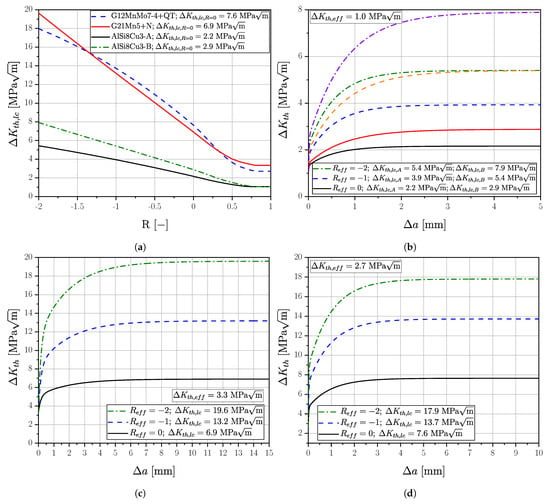
Figure 26.
Crack growth data for the investigated materials illustrating the effective stress ratio : (a) Newman curves and (b) R-curve of material AlSi8Cu3 (c) R-curve of material G21Mn5+N and (d) R-curve of material G12MnMo7-4+QT.
The effect of defect location within the evaluated layer, e.g., close to the surface or within bulk volume, is considered by the geometry factor Y. It is set to 0.73 for superficial and 0.65 for internal crack initiating imperfections, according to Radaj [89]. The depicted S/N-curves representing the mean value of fatigue testing implying both locations of fracture; see Section 3. Hence, a mean geometry correction factor was calculated for each specimen series based on the fractographic investigations, resulting probabilistic mean values between 0.65 and 0.73.
Finally, the fatigue strength for a probability of occurrence of 50% can be evaluated as intersection of defects’ size and the respective limit line (R-curve or El-Haddad) in the KT-diagram. The size of fracture initiating defects is based on the GEV-distributions of each series; see results of statistical analysis of defects in Section 3. As the basic defect distribution in the highly stressed material volume is the same, the observed difference in fatigue strength between manually polished and vibratory finished samples is traced back to the effect of the effective residual stress state. The stress ratio R affects the long-crack threshold and thereby the design limit curve of the KTD. Equation (20) depicts the dependency of the long-crack threshold range on the stress ratio, parametrized for each material as illustrated in Figure 26. Table 14 summarizes the calculated KTD fatigue design strengths for each cast alloy assuming that the load–stress ratio is applicable. This neglects purposely the effective load–stress ratio in the surface layer. Thus, this simplification can not distinct between manual polishing and vibratory finished surface treatment. The defect distribution is properly considered as -value at an occurrence level of fifty percent for each series.

Table 14.
Calculated fatigue strength of investigated series without effect of surface layer treatment ().
To incorporate the effective stress ratio within the surface layer for fatigue assessment, one has to be replace R by in Equation (20). This lead to a sound match between experiment and calculation long-life-fatigue strength for the four investigated series, as depicted in Figure 27. Even though not pronounced distinctive for all cast alloys, the R-curve concept is preferable in conservative fatigue design compared to the simpler El-Haddad’s method. This holds especially true for the high-strength cast steel. Table 15 depicts the calculated fatigue strength of each surface treatment for the four different investigated cast alloys. In general, the KTD evaluation method with effective stress ratio extension is capable to reproduce the fatigue strength changes for polished and vibratory surface treatment satisfyingly. The observed improvement is different for each material, and is based on the effective stress ratio value within the surface layer for each material. Fatigue assessment based on the KT-diagram with effective stress ratio leads to match between experiment and calculated fatigue life within ten percent in stress range for all investigated cast alloys and surface post-treatment methods.
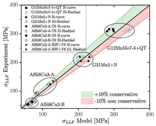
Figure 27.
Comparison of experimental data and model predictions for fatigue assessment using the layer-based probabilistic Kitagawa diagram with extension.

Table 15.
Calculated long life fatigue strength values focussing on the effect of compared to the experimental results using different surface treatments.
It should be noted that the defect-free base material strength of each alloy is not obtained directly by fatigue testing, as the effective stress ratio effect has to be considered as well. In detail, the experimentally determined, corrected fatigue strength of the polished series AlSi8Cu3-A-HIP+T6 was used as base material strength in the assessment methodology for the aluminium series. Vibratory finished samples of this defect free series revealed a estimated fatigue strength of MPa, which is 4.2% conservative compared to the experimental results for both, the R-curve as well as the EL-Haddad concept. The comparison to the experimental data are additionally depicted as black filled stars in Figure 27.
5.2. Murakami Concept
In order to incorporate the effect of local hardness change and the effect of the local stress ratio , Murakami’s approach [21] is used as a second fatigue assessment method; see Equation (21). Again, the effective stress ratio is put into operation instead of the load–stress ratio R. In addition, the measured change in surface hardness is considered for each surface treatment. The constants and of the extended Murakami approach for light metals by Noguchi et al. [109] were set to for surface, and for bulk defects, as well as . The used local hardness values are referred in Figure 17 and detailed in Section 3. The effective local load–stress ratio was again taken from the elastic plastic simulations in stabilized condition, listed in Table 13.
Figure 28 depicts the differences between experimentally determined fatigue strength and calculated one for each cast alloy, using the modified Murakami approach with effective stress ratio . It is obvious that Murakami’s empirical approach is not as well applicable as the more sophisticated R-curve concept. But for more ductile materials, as in case of cast steel G12Mn5+N and the less porosity afflicted aluminium alloy charge AlSi8Cu3-A, Murakami’s approach is also quite close to the experimental reference. Table 16 summarizes the calculated fatigue strength values of Murakami’s method using the effective stress ratio within the surface layer. It should be mentioned that the proposed extension by consideration of the effective surface layer stress ratio generally improves the accuracy of Murakami’s method, using only the load–stress ratio R. But the observed deviation in calculated fatigue strength are between 26% conservative and up to 62% non-conservative, depending on the investigated material.
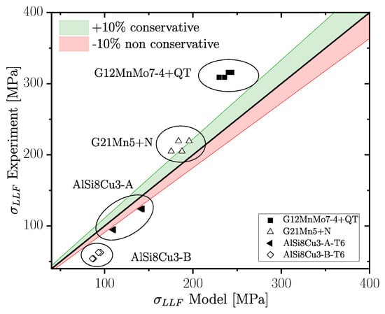
Figure 28.
Comparison between experimental data and model predictions for fatigue assessment, considering local effective stress ratio and hardness, using the modified Murakami approach.

Table 16.
Calculated fatigue strength of Murakami’s approach compared to experimental results.
Summing up, it is clearly evident from the analysis of the results in this study, that the residual stress state has to be taken into account to distinguish between polished and vibratory finished surfaces for a proper estimation of the fatigue strength. Especially if fatigue samples are surface post-treated by vibratory finishing processes for ensuring sample manufacturing process reproducibility, the tested fatigue strength can be overestimated. But if the course of the effective stress ratio is considered within the surface layer, the fatigue assessment can be properly applied, as illustrated for cast alloys using the R-curve KTD method with extension. It should be noted that the surface treatment effect can be assessed in a similar manner for materials without imperfections, in this case taking only the change of by elasto-plastic simulations accordingly into account.
6. Conclusions
The effect of vibratory finishing and the associated residual stresses were taken into account for evaluation of fatigue performance of two cast steel alloys as well as one aluminium alloy with different microstructure and heat treatment conditions. To investigate the evolution of residual stresses during cyclic loading, comprehensive numerical analysis were performed incorporating the cyclic elasto-plastic material behaviour for each cast alloy. The obtained numerical results yield an effective stress ratio dependency for each layer and implemented in fracture mechanical fatigue models such as the Kitagawa–Takahashi diagram as effective stress ratio . In addition, the suitability of Murakami’s method was studied as well. Finally, the following conclusions can be drawn from the obtained results focussing on the effect of surface treatment and related effective stress ratio in fatigue design:
- Vibratory finishing has a significant impact on the high cycle fatigue strength and reduces the scatter index of fatigue test data compared to manually operated polishing processes.
- The impact of vibratory finishing on the surface layer depends quite strongly on the yield strength of the investigated material.
- For aluminium alloys, the benefit in fatigue strength can approach thirty percent, but for high-strength cast alloys the gained increase reduces to about three percent.
- A compressive residual stress state is achieved for all examined vibratory finished specimen series and results in a corresponding improvement of fatigue strength.
- Although global elastic loading is applied in fatigue testing, the residual stress profile in the surface layer is rearranged due to cyclic loading. The modification of residual stress state was investigated with a series of elastic–plastic finite-element simulations.
- The proposed methodology for incorporating the cyclic stable effective residual stress state is capable for fatigue design of post-processing treatments such as vibratory finishing, but can be similarly applied to study other surface treatment processes such as shot-peening or case hardening as well.
- Quite accurate fatigue strength calculations within ten percent stress range deviations were obtained considering the cyclic stable residual stress profile of the numerical simulations at a certain distance from the surface using a probabilistic Kitagawa–Takahashi diagram including short crack effect, load–stress ratio and microstructure dependency.
- The more easily applicable approach of Murakami considering the local stable effective load–stress ratio and surface hardness leads to an increased fatigue scatter band, but is still applicable for ductile cast alloys with about fifteen percent in stress range deviation.
Author Contributions
Conceptualization, M.O.; methodology, M.O., M.S. and M.H.; software, M.O. and S.F.; validation, M.O., M.H. and M.S.; formal analysis, M.O. and M.H.; investigation, M.O. and M.H.; resources, M.S.; data curation, M.O., S.F. and M.H.; writing—original draft preparation, M.O.; writing—review and editing, M.O. and M.S.; visualization, M.O.; supervision, M.S.; project administration, M.S.; funding acquisition, M.S. All authors have read and agreed to the published version of the manuscript.
Funding
This research was funded by the Austrian Federal Ministry for Digital and Economic Affairs and the National Foundation for Research, Technology, and Development.
Institutional Review Board Statement
Not applicable.
Data Availability Statement
Not applicable.
Acknowledgments
The financial support by the Austrian Federal Ministry for Digital and Economic Affairs and the National Foundation for Research, Technology and Development is gratefully acknowledged.
Conflicts of Interest
The authors declare no conflict of interest. The funders had no role in the design of the study, in the collection, analyses, or interpretation of data, in the writing of the manuscript, or in the decision to publish the results.
Abbreviations
The following abbreviations are used in this manuscript:
| Defect size perpendicular to the load direction | |
| Crack opening function | |
| Kinematic material parameter | |
| Scale parameter of the GEV distribution | |
| Deviation in % between two values | |
| Fatigue range of defect free material | |
| Effective crack threshold range | |
| Long crack threshold range | |
| Long crack threshold value at tumescent loading | |
| Elastic strain amplitude | |
| Plastic strain amplitude | |
| Total strain amplitude | |
| Fatigue ductility coefficient | |
| Plastic strain | |
| Initial plastic strain | |
| Secondary dendrite arm spacing | |
| Location parameter of the GEV distribution | |
| Weighting factor for crack closure | |
| Shape parameter of the GEV distribution | |
| Stress tensor | |
| Deviatoric part of the stress tensor | |
| Stress amplitude | |
| Fatigue strength coefficient | |
| Long life fatigue strength at ten million load cycles | |
| Effective, cyclic stable residual stresses | |
| Cyclic stable residual stresses at distance from surface | |
| Cyclic stable residual stresses at distance from surface | |
| Cyclic stable residual stresses at specimen center | |
| Residual stresses in z-direction | |
| Cyclic stable residual stresses at surface | |
| Kinematic back stress tensor | |
| Deviatoric part of kinematic back stress tensor | |
| Direction of flow | |
| a | Crack length |
| EL Haddad constant | |
| Intrinsic crack length | |
| Newman coefficient | |
| b | Fatigue strength exponent |
| Stabilization rate of yield surface | |
| c | Fatigue ductility exponent |
| Kinematic material parameter | |
| Material constant of Newman curve | |
| E | Quasistatic Young’s Modulus |
| f | Yield function |
| Vickers hardness | |
| I | Isotropic part of combined hardening model |
| von Mises criterion | |
| k | Initial size of the yield function |
| Inverse slope of the S/N-curve in finite life region | |
| Inverse slope of the S/N-curve in long life region | |
| Cyclic strength coefficient | |
| Crack elongation where closure effect is completely developed | |
| Lower yield strength | |
| Cyclic strain hardening exponent | |
| p | Accumulated plastic strain |
| Probability of occurrence | |
| Probability of survival | |
| Q | Difference between initial and stabilized size of the yield surface |
| Strain ratio | |
| R | Load stress ratio |
| Arithmetic mean high of the roughness profile | |
| Mean high of the roughness profile elements | |
| Effective cyclic stable load ratio | |
| Tensile strength | |
| Fatigue scatter index of the S/N-curve | |
| Ultimate tensile strength | |
| Upper yield strength | |
| Y | Geometry factor |
| Yield strength | |
| CT | Computed tomography |
| DCPD | Direct current potential drop |
| DOM | Digital optical microscope |
| EDM | Electrical discharge machining |
| FKM | Forschungskuratorium Maschinenbau |
| GEV | Generalized extreme value distribution |
| HCF | High cycle fatigue |
| HIP | Hot isostatic pressed |
| HSV | Highly stressed volume |
| KS | Kolmogorov-Smirnov |
| KTD | Kitagawa–Takahashi diagram |
| LCF | Low cycle fatigue |
| POL | Polished surface state |
| POT | Peak over threshold sampling |
| SEM | Scanning electron microscope |
| TCD | Theory of critical distances |
| VF | Vibratory finished surface state |
| XRD | X-ray diffraction analysis |
References
- Fiedler, K.; Rolfe, B.F.; de Souza, T. Integrated Shape and Topology Optimization-Applications in Automotive Design and Manufacturing. SAE Int. J. Mater. Manuf. 2017, 10, 385–394. [Google Scholar] [CrossRef]
- Zerbst, U.; Madia, M.; Klinger, C.; Bettge, D.; Murakami, Y. Defects as a root cause of fatigue failure of metallic components. III: Cavities, dents, corrosion pits, scratches. Eng. Fail. Anal. 2019, 97, 759–776. [Google Scholar] [CrossRef]
- Tenkamp, J.; Awd, M.; Siddique, S.; Starke, P.; Walther, F. Fracture–Mechanical Assessment of the Effect of Defects on the Fatigue Lifetime and Limit in Cast and Additively Manufactured Aluminum–Silicon Alloys from HCF to VHCF Regime. Metals 2020, 10, 943. [Google Scholar] [CrossRef]
- Niu, G.; Wang, Y.; Zhu, L.; Ye, J.; Mao, J. Fluidity of casting Al–Si series alloys for automotive light-weighting: A systematic review. Mater. Sci. Technol. 2022, 38, 902–911. [Google Scholar] [CrossRef]
- Druschitz, A.P.; Fitzgerald, D.C. Lightweight Iron and Steel Castings for Automotive Applications. In Proceedings of the SAE 2000 World Congress Detroit, Warrendale, PA, USA, 31 August 2000; SAE Technical Paper Series. SAE: Warrendale, PA, USA, 2000. [Google Scholar] [CrossRef]
- Santos, J.; Gouveia, R.M.; Silva, F. Designing a new sustainable approach to the change for lightweight materials in structural components used in truck industry. J. Clean. Prod. 2017, 164, 115–123. [Google Scholar] [CrossRef]
- Sharma, V.; Zivic, F.; Adamovic, D.; Ljusic, P.; Kotorcevic, N.; Slavkovic, V.; Grujovic, N. Multi-Criteria Decision Making Methods for Selection of Lightweight Material for Railway Vehicles. Materials 2022, 16, 368. [Google Scholar] [CrossRef] [PubMed]
- Campbell, J. Complete Casting Handbook: Metal Casting Processes, Techniques and Design; Elsevier Butterworth-Heinemann: Oxford, UK, 2011. [Google Scholar]
- Campbell, J. Entrainment defects. Mater. Sci. Technol. 2013, 22, 127–145. [Google Scholar] [CrossRef]
- Olofsson, J. Local microstructure-based material performance and damage in design and finite element simulations of cast components. J. Comput. Des. Eng. 2018, 5, 419–426. [Google Scholar] [CrossRef]
- Boileau, J.M.; Allison, J.E. The effect of solidification time and heat treatment on the fatigue properties of a cast 319 aluminum alloy. Metall. Trans. 2003, 34, 1807–1820. [Google Scholar] [CrossRef]
- Zhang, L.Y.; Jiang, Y.H.; Ma, Z.; Shan, S.F.; Jia, Y.Z.; Fan, C.Z.; Wang, W.K. Effect of cooling rate on solidified microstructure and mechanical properties of aluminium-A356 alloy. J. Mater. Process. Technol. 2008, 207, 107–111. [Google Scholar] [CrossRef]
- Bermond, A.; Roume, C.; Stolarz, J.; Lenci, M.; Carton, J.F.; Klocker, H. Low Cycle Fatigue of G20Mn5 Cast Steel Relation between Microstructure and Fatigue Life. Materials 2022, 15, 7072. [Google Scholar] [CrossRef] [PubMed]
- Murakami, Y. Material defects as the basis of fatigue design. Int. J. Fatigue 2012, 41, 2–10. [Google Scholar] [CrossRef]
- Hardin, R.A.; Beckermann, C. Effect of Porosity on Deformation, Damage, and Fracture of Cast Steel. Metall. Trans. 2013, 44, 5316–5332. [Google Scholar] [CrossRef]
- Makino, T.; Shimokawa, Y.; Yamamoto, M. Fatigue Property and Design Criterion of Cast Steel for Railway Bogie Frames. Mater. Trans. 2019, 60, 950–958. [Google Scholar] [CrossRef]
- Nagel, S.; Rauber, C.; Veile, I.; Knödel, P.; Ummenhofer, T. Influence of internal imperfections on the fatigue resistance of cast steel—Testing methodology. MATEC Web Conf. 2019, 300, 09001. [Google Scholar] [CrossRef]
- Tiryakioğlu, M. Relationship between Defect Size and Fatigue Life Distributions in Al-7 Pct Si-Mg Alloy Castings. Metall. Mater. Trans. A 2009, 40, 1623–1630. [Google Scholar] [CrossRef]
- Leitner, M.; Garb, C.; Remes, H.; Stoschka, M. Microporosity and statistical size effect on the fatigue strength of cast aluminium alloys EN AC-45500 and 46200. Mater. Sci. Eng. A 2017, 707, 567–575. [Google Scholar] [CrossRef]
- Rotella, A.; Nadot, Y.; Piellard, M.; Augustin, R.; Fleuriot, M. Fatigue limit of a cast Al-Si-Mg alloy (A357-T6) with natural casting shrinkages using ASTM standard X-ray inspection. Int. J. Fatigue 2018, 114, 177–188. [Google Scholar] [CrossRef]
- Murakami, Y. Metal Fatigue: Effects of Small Defects and Nonmetallic Inclusions; Elsevier: Amsterdam, The Netherlands, 2002. [Google Scholar]
- Nourian-Avval, A.; Fatemi, A. Characterization and Analysis of Porosities in High Pressure Die Cast Aluminum by Using Metallography, X-ray Radiography, and Micro-Computed Tomography. Materials 2020, 13, 3068. [Google Scholar] [CrossRef]
- Nudelis, N.; Mayr, P. A Novel Classification Method for Pores in Laser Powder Bed Fusion. Metals 2021, 11, 1912. [Google Scholar] [CrossRef]
- Sausto, F.; Tezzele, C.; Beretta, S. Analysis of Fatigue Strength of L-PBF AlSi10Mg with Different Surface Post-Processes: Effect of Residual Stresses. Metals 2022, 12, 898. [Google Scholar] [CrossRef]
- Vaara, J.; Kunnari, A.; Frondelius, T. Literature review of fatigue assessment methods in residual stressed state. Eng. Fail. Anal. 2020, 110, 104379. [Google Scholar] [CrossRef]
- Buchanan, D.J.; John, R. Residual stress redistribution in shot peened samples subject to mechanical loading. Mater. Sci. Eng. A 2014, 615, 70–78. [Google Scholar] [CrossRef]
- Bagehorn, S.; Wehr, J.; Maier, H.J. Application of mechanical surface finishing processes for roughness reduction and fatigue improvement of additively manufactured Ti-6Al-4V parts. Int. J. Fatigue 2017, 102, 135–142. [Google Scholar] [CrossRef]
- Benedetti, M.; Berto, F.; Le Bone, L.; Santus, C. A novel Strain-Energy-Density based fatigue criterion accounting for mean stress and plasticity effects on the medium-to-high-cycle uniaxial fatigue strength of plain and notched components. Int. J. Fatigue 2020, 133, 105397. [Google Scholar] [CrossRef]
- Wang, Q.; Ji, B.; Fu, Z.; Ye, Z. Evaluation of crack propagation and fatigue strength of rib-to-deck welds based on effective notch stress method. Constr. Build. Mater. 2019, 201, 51–61. [Google Scholar] [CrossRef]
- Soriano, C.; Leunda, J.; Lambarri, J.; García Navas, V.; Sanz, C. Effect of laser surface hardening on the microstructure, hardness and residual stresses of austempered ductile iron grades. Appl. Surf. Sci. 2011, 257, 7101–7106. [Google Scholar] [CrossRef]
- Fischer, A.; Scholtes, B.; Niendorf, T. On the Influence of Surface Hardening Treatments on Microstructure Evolution and Residual Stress in Microalloyed Medium Carbon Steel. J. Mater. Eng. Perform. 2020, 29, 3040–3054. [Google Scholar] [CrossRef]
- Benedetti, M.; Fontanari, V.; Bandini, M. A simplified and fast method to predict plain and notch fatigue of shot peened high-strength aluminium alloys under reverse bending. Surf. Coat. Technol. 2014, 243, 2–9. [Google Scholar] [CrossRef]
- Crupi, G.; Taylor, D. Residual Stresses and Fatigue Prediction Using the Theory of Critical Distances. Stress 2004, 50. [Google Scholar]
- Benedetti, M.; Fontanari, V.; Santus, C.; Bandini, M. Notch fatigue behaviour of shot peened high-strength aluminium alloys: Experiments and predictions using a critical distance method. Int. J. Fatigue 2010, 32, 1600–1611. [Google Scholar] [CrossRef]
- Bagherifard, S.; Colombo, C.; Guagliano, M. Application of different fatigue strength criteria to shot peened notched components. Part 1: Fracture Mechanics based approaches. Appl. Surf. Sci. 2014, 289, 180–187. [Google Scholar] [CrossRef]
- Leitner, M.; Simunek, D.; Shah, S.F.; Stoschka, M. Numerical fatigue assessment of welded and HFMI-treated joints by notch stress/strain and fracture mechanical approaches. Adv. Eng. Softw. 2018, 120, 96–106. [Google Scholar] [CrossRef]
- Leitner, M.; Stoschka, M.; Ottersböck, M. Fatigue assessment of welded and high frequency mechanical impact (HFMI) treated joints by master notch stress approach. Int. J. Fatigue 2017, 101, 232–243. [Google Scholar] [CrossRef]
- Meier, B.; Godja, N.; Warchomicka, F.; Belei, C.; Schäfer, S.; Schindel, A.; Palcynski, G.; Kaindl, R.; Waldhauser, W.; Sommitsch, C. Influences of Surface, Heat Treatment, and Print Orientation on the Anisotropy of the Mechanical Properties and the Impact Strength of Ti 6Al 4V Processed by Laser Powder Bed Fusion. J. Solid Mech. Mater. Eng. 2022, 6, 87. [Google Scholar] [CrossRef]
- Zhou, X.; Ren, L.; Song, Z.; Li, G.; Zhang, J.; Li, B.; Wu, Q.; Li, W.; Ren, L.; Liu, Q. Advances in 3D/4D printing of mechanical metamaterials: From manufacturing to applications. Compos. Part B Eng. 2023, 254, 110585. [Google Scholar] [CrossRef]
- Schulze, V. Modern Mechanical Surface Treatment: States, Stability, Effects; Wiley-VCH: Weinheim, Germany, 2006. [Google Scholar]
- Soyama, H.; Chighizola, C.R.; Hill, M.R. Effect of compressive residual stress introduced by cavitation peening and shot peening on the improvement of fatigue strength of stainless steel. J. Mater. Process. Technol. 2021, 288, 116877. [Google Scholar] [CrossRef]
- Tan, L.; Zhang, D.; Yao, C.; Wu, D.; Zhang, J. Evolution and empirical modeling of compressive residual stress profile after milling, polishing and shot peening for TC17 alloy. J. Manuf. Process. 2017, 26, 155–165. [Google Scholar] [CrossRef]
- Zhang, J.Y.; Yao, C.F.; Cui, M.C.; Tan, L.; Sun, Y.Q. Three-dimensional modeling and reconstructive change of residual stress during machining process of milling, polishing, heat treatment, vibratory finishing, and shot peening of fan blade. Adv. Manuf. 2021, 9, 430–445. [Google Scholar] [CrossRef]
- Kumar, D.; Idapalapati, S.; Wang, W.; Narasimalu, S. Effect of Surface Mechanical Treatments on the Microstructure-Property-Performance of Engineering Alloys. Materials 2019, 12, 2503. [Google Scholar] [CrossRef]
- Lesyk, D.A.; Martinez, S.; Mordyuk, B.N.; Dzhemelinskyi, V.V.; Lamikiz, A.; Prokopenko, G.I. Post-processing of the Inconel 718 alloy parts fabricated by selective laser melting: Effects of mechanical surface treatments on surface topography, porosity, hardness and residual stress. Surf. Coat. Technol. 2020, 381, 125136. [Google Scholar] [CrossRef]
- Luo, S.; Zhou, L.; Nie, X.; Li, Y.; He, W. The compound process of laser shock peening and vibratory finishing and its effect on fatigue strength of Ti-3.5Mo-6.5Al-1.5Zr-0.25Si titanium alloy. J. Alloys Compd. 2019, 783, 828–835. [Google Scholar] [CrossRef]
- Alcaraz, J.Y.; Zhang, J.; Nagalingam, A.P.; Gopasetty, S.K.; Toh, B.L.; Gopinath, A.; Ahluwalia, K.; Ang, M.G.W.; Yeo, S.H. Numerical modeling of residual stresses during vibratory peening of a 3-stage Blisk—A multi-scale discrete element and finite element approach. J. Mater. Process. Technol. 2022, 299, 117383. [Google Scholar] [CrossRef]
- Atzeni, E.; Balestrucci, A.; Catalano, A.R.; Iuliano, L.; Priarone, P.C.; Salmi, A.; Settineri, L. Performance assessment of a vibro-finishing technology for additively manufactured components. Procedia CIRP 2020, 88, 427–432. [Google Scholar] [CrossRef]
- Sangid, M.D.; Stori, J.A.; Ferriera, P.M. Process characterization of vibrostrengthening and application to fatigue enhancement of aluminum aerospace components—Part I. Experimental study of process parameters. Int. J. Adv. Manuf. Technol. 2011, 53, 545–560. [Google Scholar] [CrossRef]
- Eifler, M.; Garretson, I.C.; Linke, B.S.; Das, J.; Torner, F.; Seewig, J. Effects of vibratory finishing of 304 stainless steel samples on areal roughness parameters: A correlational analysis for anisotropy parameters. J. Mater. Process. Technol. 2019, 273, 116256. [Google Scholar] [CrossRef]
- Stańczyk, M.; Figlus, T. The Effect of Selected Parameters of Vibro-Abrasive Processing on the Surface Quality of Products Made of 6082 Aluminium Alloy. Materials 2019, 12, 4117. [Google Scholar] [CrossRef]
- Wong, B.J.; Majumdar, K.; Ahluwalia, K.; Yeo, S.H. Effects of high frequency vibratory finishing of aerospace components. J. Mech. Sci. Technol. 2019, 33, 1809–1815. [Google Scholar] [CrossRef]
- Chan, W.L.; Ahluwalia, K.; Gopinath, A. Parametric Study of Fixtured Vibropeening. Metals 2019, 9, 910. [Google Scholar] [CrossRef]
- Canals, L.; Badreddine, J.; McGillivray, B.; Miao, H.Y.; Levesque, M. Effect of vibratory peening on the sub-surface layer of aerospace materials Ti-6Al-4V and E-16NiCrMo13. J. Mater. Process. Technol. 2019, 264, 91–106. [Google Scholar] [CrossRef]
- Kumar, D.; Idapalapati, S.; Wang, W.; Child, D.J.; Haubold, T.; Wong, C.C. Microstructure-mechanical property correlation in shot peened and vibro-peened Ni-based superalloy. J. Mater. Process. Technol. 2019, 267, 215–229. [Google Scholar] [CrossRef]
- Segurado, E.; Belzunce, J.; Fernández, I. Enhanced Fatigue Behavior in Quenched and Tempered High-Strength Steel by Means of Double Surface Treatments. J. Mater. Eng. Perform. 2019, 28, 2094–2102. [Google Scholar] [CrossRef]
- Hamidi Nasab, M.; Giussani, A.; Gastaldi, D.; Tirelli, V.; Vedani, M. Effect of Surface and Subsurface Defects on Fatigue Behavior of AlSi10Mg Alloy Processed by Laser Powder Bed Fusion (L-PBF). Metals 2019, 9, 1063. [Google Scholar] [CrossRef]
- Rennert, R.; Maschinenbau, F.F. Rechnerischer Festigkeitsnachweis für Maschinenbauteile aus Stahl, Eisenguss- und Aluminiumwerkstoffen, 6th ed.; FKM-Richtlinie, VDMA-Verl.: Frankfurt am Main, Germany, 2012. [Google Scholar]
- Taylor, D. Geometrical effects in fatigue: A unifying theoretical model. Int. J. Fatigue 1999, 21, 413–420. [Google Scholar] [CrossRef]
- Taylor, D. The theory of critical distances. Eng. Fract. Mech. 2008, 75, 1696–1705. [Google Scholar] [CrossRef]
- El Haddad, M.H.; Topper, T.H.; Smith, K.N. Prediction of non propagating cracks. Eng. Fract. Mech. 1979, 11, 573–584. [Google Scholar] [CrossRef]
- Susmel, L.; Taylor, D. The theory of critical distances to predict static strength of notched brittle components subjected to mixed-mode loading. Eng. Fract. Mech. 2008, 75, 534–550. [Google Scholar] [CrossRef]
- Chiandussi, G.; Rossetto, M. Evaluation of the fatigue strength of notched specimens by the point and line methods with high stress ratios. Int. J. Fatigue 2005, 27, 639–650. [Google Scholar] [CrossRef]
- Susmel, L. The theory of critical distances: A review of its applications in fatigue. Eng. Fract. Mech. 2008, 75, 1706–1724. [Google Scholar] [CrossRef]
- Olmi, G.; Comandini, M.; Freddi, A. Fatigue on Shot-Peened Gears: Experimentation, Simulation and Sensitivity Analyses. Strain 2010, 46, 382–395. [Google Scholar] [CrossRef]
- Lee, C.H.; Chang, K.H.; van Do, V.N. Finite element modeling of residual stress relaxation in steel butt welds under cyclic loading. Eng. Struct. 2015, 103, 63–71. [Google Scholar] [CrossRef]
- Kwofie, S. Description and simulation of cyclic stress-strain response during residual stress relaxation under cyclic load. Procedia Eng. 2011, 10, 293–298. [Google Scholar] [CrossRef]
- Morrow, J.; Sinclair, G.M. Cycle-Dependent Stress Relaxation. In Symposium on Basic Mechanisms of Fatigue; ASTM International: West Conshohocken, PA, USA, 1959; pp. 83–109. [Google Scholar] [CrossRef]
- Paul, S.K.; Stanford, N.; Taylor, A.; Hilditch, T. The effect of low cycle fatigue, ratcheting and mean stress relaxation on stress–strain response and microstructural development in a dual phase steel. Int. J. Fatigue 2015, 80, 341–348. [Google Scholar] [CrossRef]
- Landgraf, R.W.; Chernenkoff, R.A. Residual stress effects on fatigue of surface processed steels. Anal. Exp. Methods Residual Stress Eff. Fatigue ASTM STP 1988, 1004, 1–12. [Google Scholar]
- Lee, Y. Effects of redistributing residual stress on the fatigue behavior of ss330 weldment. Int. J. Fatigue 1998, 20, 565–573. [Google Scholar] [CrossRef]
- Hensel, J.; Nitschke-Pagel, T.; Tchoffo Ngoula, D.; Beier, H.T.; Tchuindjang, D.; Zerbst, U. Welding residual stresses as needed for the prediction of fatigue crack propagation and fatigue strength. Eng. Fract. Mech. 2018, 198, 123–141. [Google Scholar] [CrossRef]
- Han, S.; Lee, T.; Shin, B. Residual stress relaxation of welded steel components under cyclic load. Steel Res. 2002, 73, 414–420. [Google Scholar] [CrossRef]
- Wang, X.; Meng, Q.; Hu, W. Fatigue life prediction for butt–welded joints considering weld–induced residual stresses and initial damage, relaxation of residual stress, and elasto–plastic fatigue damage. Fatigue Fract. Eng. Mater. Struct. 2018, 42, 1373–1386. [Google Scholar] [CrossRef]
- Foss, B.J.; Gray, S.; Hardy, M.C.; Stekovic, S.; McPhail, D.S.; Shollock, B.A. Analysis of shot-peening and residual stress relaxation in the nickel-based superalloy RR1000. Acta Mater. 2013, 61, 2548–2559. [Google Scholar] [CrossRef]
- Kim, J.C.; Cheong, S.K.; Noguchi, H. Residual stress relaxation and low- and high-cycle fatigue behavior of shot-peened medium-carbon steel. Int. J. Fatigue 2013, 56, 114–122. [Google Scholar] [CrossRef]
- Leguinagoicoa, N.; Albizuri, J.; Larrañaga, A. Fatigue improvement and residual stress relaxation of shot-peened alloy steel DIN 34CrNiMo6 under axial loading. Int. J. Fatigue 2022, 162, 107006. [Google Scholar] [CrossRef]
- Chaboche, J.L. A review of some plasticity and viscoplasticity constitutive theories. Int. J. Plast. 2008, 24, 1642–1693. [Google Scholar] [CrossRef]
- Chaboche, J.L. Time-independent constitutive theories for cyclic plasticity. Int. J. Plast. 1986, 2, 149–188. [Google Scholar] [CrossRef]
- Halama, R.; Sedlk, J.; Sofer, M. Phenomenological Modelling of Cyclic Plasticity. In Numerical Modelling; Miidla, P., Ed.; IntechOpen: London, UK, 2012. [Google Scholar] [CrossRef]
- Seisenbacher, B.; Winter, G.; Grün, F. Improved Approach to Determine the Material Parameters for a Combined Hardening Model. Mater. Sci. Appl. 2018, 9, 357–367. [Google Scholar] [CrossRef]
- Tenkamp, J.; Koch, A.; Knorre, S.; Krupp, U.; Michels, W.; Walther, F. Defect-correlated fatigue assessment of A356-T6 aluminum cast alloy using computed tomography based Kitagawa-Takahashi diagrams. Int. J. Fatigue 2018, 108, 25–34. [Google Scholar] [CrossRef]
- Tenkamp, J.; Stern, F.; Walther, F. Uniform Fatigue Damage Tolerance Assessment for Additively Manufactured and Cast Al-Si Alloys by Linking Novel Elastic-Plastic Facture Mechanical Approaches. SSRN Electron. J. 2022. [Google Scholar] [CrossRef]
- Beretta, S.; Romano, S. A comparison of fatigue strength sensitivity to defects for materials manufactured by AM or traditional processes. Int. J. Fatigue 2017, 94, 178–191. [Google Scholar] [CrossRef]
- Romano, S.; Brückner-Foit, A.; Brandão, A.; Gumpinger, J.; Ghidini, T.; Beretta, S. Fatigue properties of AlSi10Mg obtained by additive manufacturing: Defect-based modelling and prediction of fatigue strength. Eng. Fract. Mech. 2018, 187, 165–189. [Google Scholar] [CrossRef]
- Gao, T.; Ji, C.; Zhan, Z.; Huang, Y.; Liu, C.; Hu, W.; Meng, Q. A novel defect-based fatigue damage model coupled with an optimized neural network for high-cycle fatigue analysis of casting alloys with surface defect. Int. J. Fatigue 2023, 170, 107538. [Google Scholar] [CrossRef]
- Fischer, C.; Schweizer, C. Experimental investigation of the damage characteristics of two cast aluminium alloys: Part III—Influence of the local microstructure and initial defect size on the fatigue properties. Int. J. Fatigue 2021, 152, 106388. [Google Scholar] [CrossRef]
- Nourian-Avval, A.; Fatemi, A. Fatigue Design with High Pressure Die Cast Aluminum Including the Effects of Defects, Section Size, Stress Gradient, and Mean Stress. Mater. Today Commun. 2020, 25, 101567. [Google Scholar] [CrossRef]
- Radaj, D. Geometry correction for stress intesity at elliptical cracks. Weld. Cut. 1977, 29, 198–402. [Google Scholar]
- Kitagawa, H.; Takahashi, S. (Eds.) Applicability of Fracture Mechanics to Very Small Cracks or the Cracks in the Early Stage; American Society for Metals: Detroit, MI, USA, 1976. [Google Scholar]
- Chapetti, M.D. Fatigue propagation threshold of short cracks under constant amplitude loading. Int. J. Fatigue 2003, 25, 1319–1326. [Google Scholar] [CrossRef]
- Maierhofer, J.; Pippan, R.; Gänser, H.P. Modified NASGRO equation for physically short cracks. Int. J. Fatigue 2014, 59, 200–207. [Google Scholar] [CrossRef]
- Oberreiter, M.; Aigner, R.; Pomberger, S.; Leitner, M.; Stoschka, M. Impact of microstructural properties on the crack threshold of aluminium castings. Eng. Fract. Mech. 2021, 241, 107431. [Google Scholar] [CrossRef]
- Oberreiter, M.; Fladischer, S.; Stoschka, M.; Leitner, M. A Probabilistic Fatigue Strength Assessment in AlSi-Cast Material by a Layer-Based Approach. Metals 2022, 12, 784. [Google Scholar] [CrossRef]
- Gumpinger, J.; Brandão, A.D.; Beevers, E.; Rohr, T.; Ghidini, T.; Beretta, S.; Romano, S. Expression of Additive Manufacturing Surface Irregularities through a Flaw-Based Assessment. In Structural Integrity of Additive Manufactured Parts; Shamsaei, N., Daniewicz, S., Hrabe, N., Beretta, S., Waller, J., Seifi, M., Eds.; ASTM International: West Conshohocken, PA, USA, 2020; pp. 234–249. [Google Scholar] [CrossRef]
- Schneller, W.; Leitner, M.; Leuders, S.; Sprauel, J.M.; Grün, F.; Pfeifer, T.; Jantschner, O. Fatigue strength estimation methodology of additively manufactured metallic bulk material. Addit. Manuf. 2020, 39, 101688. [Google Scholar] [CrossRef]
- Edwards, P.; Ramulu, M. Fatigue performance evaluation of selective laser melted Ti–6Al–4V. Mater. Sci. Eng. A 2014, 598, 327–337. [Google Scholar] [CrossRef]
- Cuellar, S.D.; Hill, M.R.; DeWald, A.T.; Rankin, J.E. Residual stress and fatigue life in laser shock peened open hole samples. Int. J. Fatigue 2012, 44, 8–13. [Google Scholar] [CrossRef]
- Luo, Y.; Wu, S.; Zhao, X.; Hu, Y.; Li, C.; Shen, Z.; Zhong, X. Three-dimensional correlation of damage criticality with the defect size and lifetime of externally impacted 25CrMo4 steel. Mater. Des. 2020, 195, 109001. [Google Scholar] [CrossRef]
- Lados, D.A.; Apelian, D. The effect of residual stress on the fatigue crack growth behavior of Al-Si-Mg cast alloys—Mechanisms and corrective mathematical models. Metall. Trans. 2006, 37, 133–145. [Google Scholar] [CrossRef]
- Leuders, S.; Thöne, M.; Riemer, A.; Niendorf, T.; Tröster, T.; Richard, H.A.; Maier, H.J. On the mechanical behaviour of titanium alloy TiAl6V4 manufactured by selective laser melting: Fatigue resistance and crack growth performance. Int. J. Fatigue 2013, 48, 300–307. [Google Scholar] [CrossRef]
- Piette, T.D.; Warren, R.J.; Spangenberger, A.G.; Hummelt, E.J.; Lados, D.A. Microstructure evolution, fatigue crack growth, and ultrasonic fatigue in As-fabricated laser powder bed and conventionally cast Al–10Si-0.4Mg: A mechanistic understanding and integrated flaw-sensitive fatigue design methods. Mater. Sci. Eng. A 2021, 825, 141892. [Google Scholar] [CrossRef]
- Newman, J.C. A crack opening stress equation for fatigue crack growth. Int. J. Fract. 1984, 24, R131–R135. [Google Scholar] [CrossRef]
- Miller, K.J. The short crack problem. Fatigue Fract. Eng. Mater. Struct. 1982, 5, 223–232. [Google Scholar] [CrossRef]
- Miller, K.J.; de los Rios, E.R. The Behaviour of Short Fatigue Cracks; Mechanical Engineering Publications: Suffolk, UK, 1986. [Google Scholar]
- Tiryakioğlu, M. Statistical distributions for the size of fatigue-initiating defects in Al–7%Si–0.3%Mg alloy castings: A comparative study. Mater. Sci. Eng. A 2008, 497, 119–125. [Google Scholar] [CrossRef]
- Beretta, S. More than 25 years of extreme value statistics for defects: Fundamentals, historical developments, recent applications. Int. J. Fatigue 2021, 151, 106407. [Google Scholar] [CrossRef]
- Romano, S.; Brandão, A.; Gumpinger, J.; Gschweitl, M.; Beretta, S. Qualification of AM parts: Extreme value statistics applied to tomographic measurements. Mater. Des. 2017, 131, 32–48. [Google Scholar] [CrossRef]
- Noguchi, H.; Morishige, K.; Fujii, T.; Kawazoe, T.; Hamada, S. Proposal of method for estimation stress intensity factor range on small crack for light metals. In Proceedings of the 56th JSMS Annual Meetings, Melbourne, Australia, 15–20 July 2007; pp. 138–197. [Google Scholar]
- Ernst, F.; Kube, D.; Klaus, G.; Nemak Dillingen GmbH. Al-Kurbelgehäuse mit thermisch gespritzter Eisenbasisbeschichtung: Gießtechnische Anforderungen. Giesserei 2013, 100, 44–51. [Google Scholar]
- DIN EN 1706; Aluminium and Aluminium Alloys-Castings-Chemical Composition and Mechanical Properties, German version EN 1706:2010. Association Française de Normalisation: Paris, France, 2013.
- ASTM-A536; Specification for Ductile Iron Castings. ASTM: West Conshohocken, PA, USA, 1999.
- SEW685; Cryogenic Steel Casting/Steel Castings Having High Impact Strength at Low Temperatures-Technical Delivery Conditions. SEW: Bruchsal, Germany, 2000.
- SEW 520; Hochfester Stahlguß mit guter Schweißeignung. SEW: Bruchsal, Germany, 1996.
- Horvath, M.; Oberreiter, M.; Stoschka, M. Energy-Based Fatigue Assessment of Defect-Afflicted Cast Steel Components by Means of a Linear-Elastic Approach. Appl. Sci. 2023, 13, 3768. [Google Scholar] [CrossRef]
- ISO 12106; Metallic Materials-Fatigue Testing-Axial-Strain-Controlled Method. ISO: Geneva, Switzerland, 2017.
- E08 Committee; Test Method for Strain-Controlled Fatigue Testing. ASTM International: West Conshohocken, PA, USA, 2020. [CrossRef]
- DIN 50100; Load Controlled Fatigue Testing-Execution and Evaluation of Cyclic Tests at Constant Load Amplitudes on Metallic Specimens and Components. DIN: Berlin, Germany, 2022.
- ISO 1099; Metallic Materialsy-Fatigue Testing-Axial Force-Controlled Method. ISO: Geneva, Switzerland, 2006.
- Oberreiter, M.; Pomberger, S.; Leitner, M.; Stoschka, M. Validation Study on the Statistical Size Effect in Cast Aluminium. Metals 2020, 10, 710. [Google Scholar] [CrossRef]
- Oberreiterr, M.; Stoschka, M.; Horvath, M.; Fladischer, S. Effect of local microstructure on fatigue and related failure mechanisms in AlSi-castings. Procedia Struct. Integr. 2023, 43, 240–245. [Google Scholar] [CrossRef]
- DIN EN 3988; Test Methods for Metallic Materials-Constant Amplitude Strain-Controlled Low Cycle Fatigue Testing. DIN: Berlin, Germany, 1998.
- DIN EN 15305:2009-01; Non-Destructive Testing-Test Method for Residual Stress Analysis by X-ray Diffraction. EN_15305:2008. DIN: Berlin, Germany, 2009. [CrossRef]
- ASTM-E915-16; Test Method for Verifying the Alignment of X-ray Diffraction Instrumentation for Residual Stress Measurement. ASTM International: West Conshohocken, PA, USA, 2016. [CrossRef]
- ASTM-E2860-12; Test Method for Residual Stress Measurement by X-ray Diffraction for Bearing Steels. ASTM International: West Conshohocken, PA, USA, 2012. [CrossRef]
- ASTM E384; Standard Test Method for Microindentation Hardness of Materials. ASTM International: West Conshohocken, PA, USA, 1999. [CrossRef]
- Madia, M.; Vojtek, T.; Duarte, L.; Zerbst, U.; Pokorný, P.; Jambor, M.; Hutař, P. Determination of fatigue crack propagation thresholds for steel in presence of environmental effects. Int. J. Fatigue 2021, 153, 106449. [Google Scholar] [CrossRef]
- Pippan, R. The effective threshold of fatigue crack propagation in aluminium alloys. I. The influence of yield stress and chemical composition. Philos. Mag. A 1998, 77, 861–873. [Google Scholar] [CrossRef]
- Pippan, R.; Plöchl, L.; Klanner, F.; Stüwe, H.P. The use of fatigue specimens precracked in compression for measuring threshold values and crack growth. J. Test. Eval. 1994, 22, 98–103. [Google Scholar]
- Newman, J.C., Jr.; Yamada, Y. Compression precracking methods to generate near-threshold fatigue-crack-growth-rate data. Int. J. Fatigue 2010, 32, 879–885. [Google Scholar] [CrossRef]
- Tabernig, B.; Pippan, R. Determination of the length dependence of the threshold for fatigue crack propagation. Eng. Fract. Mech. 2002, 69, 899–907. [Google Scholar] [CrossRef]
- ASTM E739; Practice for Statistical Analysis of Linear or Linearized Stress-Life (S-N) and Strain-Life (-N) Fatigue Data. ASTM International: West Conshohocken, PA, USA, 1998. [CrossRef]
- Dengel, D. Die arc sin √P-Transformation—ein einfaches Verfahren zur grafischen und rechnerischen Auswertung geplanter Wöhlerversuche. Mater. Und Werkst. 1975, 6, 253–261. [Google Scholar] [CrossRef]
- Garb, C.; Leitner, M.; Grün, F. Application of √area-concept to assess fatigue strength of AlSi7Cu0.5Mg casted components. Eng. Fract. Mech. 2017, 185, 61–71. [Google Scholar] [CrossRef]
- Aigner, R.; Pomberger, S.; Leitner, M.; Stoschka, M. On the Statistical Size Effect of Cast Aluminium. Materials 2019, 12, 1578. [Google Scholar] [CrossRef]
- Horvath, M.; Oberreiter, M.; Stoschka, M.; Leitner, M. Set-up of a Generalized Dataset for Crack-Closure-Mechanisms of Cast Steel. J. Cast. Mater. Eng. 2021, 5, 84–88. [Google Scholar] [CrossRef]
- Kolitsch, S.; Gänser, H.P.; Maierhofer, J.; Pippan, R. Fatigue crack growth threshold as a design criterion—Statistical scatter and load ratio in the Kitagawa-Takahashi diagram. IOP Conf. Ser. Mater. Sci. Eng. 2016, 119, 012015. [Google Scholar] [CrossRef]
- Manson, S.S. Behavior of Materials Under Conditions of Thermal Stress; NASA: Washington, DC, USA, 1954.
- Coffin, L.F. A study of the effect of cyclic thermal stresses on a ductile material. Trans. ASME 1954, 76, 931–950. [Google Scholar] [CrossRef]
- Basquin, O.H. The exponential law of endurance tests. Am. Soc. Test Mater. Proc. 1910, 10, 625–630. [Google Scholar]
- Manson, S.S. Fatigue: A complex subject-Some simple approximations. Exp. Mech. 1965, 5, 193–226. [Google Scholar] [CrossRef]
- Ramberg, W.; Osgood, W.R. Description of Stress-Strain Curves by Three Parameters; NASA: Washington, DC, USA, 1943.
- Lukáš, P.; Klesnil, M. Cyclic stress-strain response and fatigue life of metals in low amplitude region. Mater. Sci. Eng. 1973, 11, 345–356. [Google Scholar] [CrossRef]
- Nieslony, A.; Dsoki, C.; Kaufmann, H.; Krug, P. New method for evaluation of the Manson–Coffin–Basquin and Ramberg–Osgood equations with respect to compatibility. Int. J. Fatigue 2008, 30, 1967–1977. [Google Scholar] [CrossRef]
- Sanchez, A.G.; You, C.; Leering, M.; Glaser, D.; Furfari, D.; Fitzpatrick, M.E.; Wharton, J.; Reed, P. Effects of laser shock peening on the mechanisms of fatigue short crack initiation and propagation of AA7075-T651. Int. J. Fatigue 2021, 143, 106025. [Google Scholar] [CrossRef]
- Schindelin, J.; Arganda-Carreras, I.; Frise, E.; Kaynig, V.; Longair, M.; Pietzsch, T.; Preibisch, S.; Rueden, C.; Saalfeld, S.; Schmid, B.; et al. Fiji: An open-source platform for biological-image analysis. Nat. Methods 2012, 9, 676–682. [Google Scholar] [CrossRef]
- Åman, M.; Wada, K.; Matsunaga, H.; Remes, H.; Marquis, G. The influence of interacting small defects on the fatigue limits of a pure iron and a bearing steel. Int. J. Fatigue 2020, 135, 105560. [Google Scholar] [CrossRef]
- Beretta, S.; Murakami, Y. Statistical analysis of defects for fatigue strength prediction and quality control of materials. Fatigue Fract. Eng. Mater. Struct. 1998, 21, 1049–1065. [Google Scholar] [CrossRef]
- Massey, F.J., Jr. The Kolmogorov-Smirnov test for goodness of fit. J. Am. Stat. Assoc. 1951, 46, 68–78. [Google Scholar] [CrossRef]
- Coles, S. An Introduction to Statistical Modeling of Extreme Values; Springer Series in Statistics; Springer: London, UK; Berlin/Heidelberg, Germany, 2001. [Google Scholar] [CrossRef]
- Hu, Y.; Scarrott, C. evmix: An R package for Extreme Value Mixture Modeling, Threshold Estimation and Boundary Corrected Kernel Density Estimation. J. Stat. Softw. 2018, 84, 1–27. [Google Scholar] [CrossRef]
- Scarrott, C.; MacDonald, A. A review of extreme value threshold estimation and uncertainty quantification. Revstat-Stat. J. 2012, 10, 33–60. [Google Scholar]
- Smith, D. Experimental measurement and finite element simulation of the interaction between residual stresses and mechanical loading. Int. J. Fatigue 2001, 23, 293–302. [Google Scholar] [CrossRef]
Disclaimer/Publisher’s Note: The statements, opinions and data contained in all publications are solely those of the individual author(s) and contributor(s) and not of MDPI and/or the editor(s). MDPI and/or the editor(s) disclaim responsibility for any injury to people or property resulting from any ideas, methods, instructions or products referred to in the content. |
© 2023 by the authors. Licensee MDPI, Basel, Switzerland. This article is an open access article distributed under the terms and conditions of the Creative Commons Attribution (CC BY) license (https://creativecommons.org/licenses/by/4.0/).