Article

Synthesis of Mesoporous and Hollow SiO2@ Eu(TTA)3phen with Enhanced Fluorescence Properties

Institute of Hybrid Materials, National Center of International Research for Hybrid Materials Technology, National Base of International Science & Technology Cooperation, College of Materials Science and Engineering, Qingdao University, Qingdao 266071, China
*
Authors to whom correspondence should be addressed.
Materials 2023, 16(13), 4501; https://doi.org/10.3390/ma16134501
Submission received: 8 May 2023 / Revised: 13 June 2023 / Accepted: 19 June 2023 / Published: 21 June 2023

Abstract

:
Lanthanide ions are extensively utilized in optoelectronic materials, owing to their narrow emission bandwidth, prolonged lifetime, and elevated fluorescence quantum yield. Inorganic non-metallic materials commonly serve as host matrices for lanthanide complexes, posing noteworthy challenges regarding loading quantity and fluorescence performance stability post-loading. In this investigation, an enhanced Stöber method was employed to synthesize mesoporous hollow silica, and diverse forms of SiO2@Eu(TTA)3phen (S@Eu) were successfully prepared. Transmission electron microscopy (TEM), energy-dispersive X-ray spectroscopy (EDS), Fourier-transform infrared (FTIR) spectroscopy, and X-ray photoelectron spectroscopy (XPS) outcomes revealed the effective binding of silica with Eu(TTA)3phen through both physical adsorption and chemical bonding. This includes the formation of Si-O-C bonds between silica and the ligand, as well as Si-O-Eu bonds between silica and europium ions. Fluorescence tests demonstrated that the mesoporous SiO2@Eu(TTA)3phen(MS@Eu) composite exhibited the highest fluorescence intensity among the three structured silica composites, with a notable enhancement of 46.60% compared to the normal SiO2@Eu(TTA)3phen composite. The Brunauer–Emmett–Teller (BET) analysis indicated that the specific surface area plays a crucial role in influencing the fluorescence intensity of SiO2@Eu(TTA)3phen, whereby the prepared mesoporous hollow silica further elevated the fluorescence intensity by 61.49%. Moreover, SiO2@Eu(TTA)3phen demonstrated 11.11% greater cyclic stability, heightened thermal stability, and enhanced alkaline resistance relative to SiO2@Eu(TTA)3phen.

1. Introduction

Rare-earth metal elements possess a distinctive electronic structure characterized by the 4f subshell, which bestows upon them exceptional optical, electrical, and magnetic properties [1,2,3]. They have found widespread utilization across various industries, including the military, metallurgy, petrochemicals, electronics, glass and ceramics, and agriculture. In particular, rare-earth metals have gained prominence in high-tech sectors such as new materials and electronics, and they are recognized as strategic resources by numerous nations worldwide [4]. Among the diverse avenues of research into functional rare-earth materials, the investigation of luminescent rare-earth materials holds paramount importance [5,6,7,8,9]. Owing to the limited molar absorptivity (less than 10 L mol−1 cm−1) of trivalent lanthanide ions and the forbidden f-f transitions, only a minute fraction of radiation directly excites the 4f level of rare-earth ions, resulting in feeble luminescence. The effective solution lies in the incorporation of rare-earth complexes into inorganic materials. In this approach, organic ligands possessing strong absorption bands in the ultraviolet (UV) region can capture more light energy than the lanthanide ions themselves. Subsequently, the excited energy is transferred from the organic ligands to the lanthanide ions through intramolecular energy transfer, enabling the sensitization of rare-earth ions to emit stronger light compared to pure lanthanide ions [10]. The rigid lattice structure of inorganic materials provides a stable microenvironment for luminescent lanthanide ions. The incorporation of lanthanide complexes into inorganic materials offers several advantages, including large Stoke shifts, narrow emission spectra, prolonged lifetimes, and high photochemical stability [11,12,13,14,15,16,17]. These merits endow lanthanide-doped inorganic materials with significant advantages across numerous applications, laying a solid foundation for modern technologies such as lighting, photon communication, battery devices, and bioimaging [18,19,20,21].
Silicon dioxide, a vital inorganic compound, possesses remarkable chemical stability and hardness. It features a compact and rigid crystal structure, along with exceptional insulation performance and biocompatibility. Silicon dioxide finds extensive application in the fabrication of optical glass [22], semiconductor devices [23], catalysts [24], coatings [25,26], ceramics [27], rubber [28], and plastics [29]. Moreover, it is widely employed in the medical [30], cosmetic [31], food [32], and environmental protection fields [33]. Within the realm of materials research, mesoporous silica and hollow silica have emerged as prominent topics of exploration. Mesoporous silica refers to a porous material characterized by a regular pore structure, with pore sizes ranging from 2 to 50 nanometers [34,35]. Several methods, such as the sol–gel method, hydrothermal method, and electrochemical method, can be employed for synthesizing mesoporous silica. Due to its adjustable pore structure, substantial specific surface area, controllable pore size, and high surface activity, mesoporous silica finds versatile applications in adsorption, catalysis, separation, sensing, and various other fields [36]. On the other hand, hollow silica is a material with a hollow internal structure and a solid silicon oxide exterior. Unlike mesoporous silica, there are relatively fewer methods for synthesizing hollow silica, primarily including the template method, membrane reaction method, and hydrothermal method [26,37]. Hollow silica possesses advantages such as a high specific surface area, hollow structure, and controllable pore size, making it widely applicable in areas such as drug delivery, catalyst carriers, and sensors. The common approaches for synthesizing mesoporous silica and hollow silica mainly involve the employment of either the hard template method or the soft template method [38,39]. The hard template method offers advantages such as precise preparation, controllable pore size, and excellent pore connectivity [40]. However, it is associated with drawbacks such as complex preparation procedures, the necessity for template and deposition material preparation, and the potential for pore channel deformation or shrinkage following template removal. In contrast, the soft template method is characterized by a simpler preparation process, a wider range of pore sizes, and favorable pore connectivity [41]. Nonetheless, it exhibits disadvantages such as lower pore size accuracy and uneven pore size distribution. A template-free method for synthesizing hollow silica presents advantages such as simplicity, controllable pore size, large-scale production, and minimal pollution, thus holding great potential for further exploration [42,43,44,45,46,47].
Silica-based rare-earth materials exhibit a wide range of applications [48,49,50,51,52,53,54]. Notably, Tin-gyun Wang et al. [55] recently presented a novel approach for fabricating transparent Ce/Tb co-doped yttrium pyrosilicate (YPS) nanocrystal silica fibers using the C2 laser heating method. By embedding Ce3+ and Tb3+ ions, they achieved an impressive energy transfer efficiency of up to 59.87% and improved fluorescence performance. This advancement positions the material as a promising candidate for scintillators, fiber lasers, and phosphors. In a separate investigation conducted by Yujuan He et al. [56], films of europium-doped yttrium orthovanadate (YVO4:Eu) and hollow silica nanoparticles (HSNPs) were prepared and applied onto a glass cover of a polycrystalline silicon solar cell. The resulting film demonstrated downshifting and anti-reflection capabilities, effectively capturing ultraviolet photons and minimizing reflection. This innovation renders the material suitable for integration into solar cell modules.
Previous research on the combination of rare-earth metals and silica has predominantly focused on silica fibers or thin films [57], while studies exploring the combination of distinct structures of spherical silica and rare-earth complexes have been scarce. This study aimed to address this gap by preparing silica spheres with varying degrees of internal and external shrinkage. Through ultrasonic and heating treatments, silica spheres with diverse morphologies, including solid, mesoporous, and hollow structures, were successfully obtained. The rare-earth complex Eu(TTA)3phen was subsequently adsorbed onto the surfaces of these silica spheres, resulting in impressive fluorescence performance (Figure 1). A comparison of the fluorescence performance with other structures of SiO2@Eu(TTA)3phen revealed that mesoporous SiO2@Eu(TTA)3phen exhibited superior performance and demonstrated significant potential in battery devices. Furthermore, the fluorescence intensity variations and cyclic stability of SiO2@Eu(TTA)3phen and Eu(TTA)3phen were evaluated under different environmental temperatures and pH values, with SiO2@Eu(TTA)3phen demonstrating excellent performance.

2. Materials and Methods

2.1. Materials

Ethanol, tetramethylammonium hydroxide (TMAH), and tetraethyl orthosilicate (TEOS) were acquired from Beijing Chemical Corporation. Ammonium hydroxide (AR grade) and 1,10-phenanthroline (phen) were obtained from Sinopharm Chemical Reagent Co., Ltd. (Shanghai, China). Europium oxide was sourced from Darui Company (Shanghai, China). Trifluoroacetylacetone (TTA) was procured from Shanghai McLean Biochemical Co., Ltd. Solvent-grade ethanol was utilized directly without further treatment. Ethyl orthosilicate underwent distillation prior to use. High-purity water (Pall Purelab Plus) with a resistivity of 18 M Ω/cm was employed in all experimental procedures.

2.2. Preparation of Silica Spheres

The modified Stöber method [58] was employed for the preparation process. To synthesize silica spheres, a solution containing 50 mL of ethanol, 1.0 mL of water, and 1.0 mL of 0.1 M tetramethylammonium hydroxide (TMAH) was introduced into an oil bath placed within a three-necked flask. Subsequently, 1.25 mL of tetraethyl orthosilicate (TEOS) was added to the solution, which was stirred at a rate of 800 rpm for a duration of three hours. Afterward, the mixture underwent centrifugation at 10,000 rpm for a period of 20 min, allowing for the collection of the solid precipitates.

2.3. Preparation of Hollow Silica

The collected solid precipitates were introduced into 50 mL of boiling water containing an appropriate amount of TMAH and subjected to an etching process for a duration of three hours. Following etching, the mixture underwent centrifugation at 10,000 rpm, allowing for the collection of the resulting solid materials.

2.4. Preparation of Mesoporous Silica

The collected solid precipitates were washed twice and subsequently added to hot water at a temperature of 90 °C, along with an appropriate amount of TMAH, for etching over a period of three hours. Following the etching process, the mixture underwent centrifugation at 10,000 rpm, allowing for the collection of the resulting solid material.

2.5. Preparation of Mesoporous Hollow SiO2

The collected silica solids were introduced into an ethanol solution of TMAH with a pH of 10.8 and subjected to sonication for a duration of 30 min. Subsequently, the mixture was centrifuged, and the resulting solid precipitates were collected. These solids were further subjected to heating and stirring in boiling water for a period of 3 h. After undergoing centrifugation once again, the solids were sonicated and washed twice using ethanol.

2.6. Preparation of SiO2@Eu(TTA)3phen with Four Morphologies

In order to prepare silica spheres with different morphologies, a mixture of 9.5 mL of ethanol and 0.1 mL of 0.1 M phenanthroline (phen) solution was added to the previously obtained silicon dioxide spheres with varying morphologies. The mixture was then subjected to sonication for a duration of 30 min. Subsequently, 0.1 mL of 0.1 M EuCl3 and 0.3 mL of 0.1 M thenoyltrifluoroacetone (TTA) were added to the mixture, which was stirred for three hours at room temperature. After undergoing centrifugation, the solid precipitates were collected and washed twice using ethanol.

2.7. Preparation of SiO2@Eu(TTA)3phen with Three Morphologies

In a three-necked flask immersed in an oil bath, mix 50 mL of ethanol, 1.0 mL of water, and 1.0 mL of TMAH (0.1 M). Add 5 mL of TEOS to the mixture and stir at 800 rpm for 3 h. Centrifuge the mixture at 10,000 rpm for 20 min and collect the solid. Mix the prepared silica spheres with 9.5 mL of ethanol and 0.1 mL of phen (0.1 M) solution. Ultrasonicate the mixture for 30 min. Add 0.1 mL of EuCl3 (0.1 M), 0.3 mL of TTA (0.1 M), and 0.35 mL of NH4OH (0.1 M) to the solution and stir at room temperature for 2.5 h. Collect the solid after centrifugation. Repeat this step three times to prepare three sets of samples.
Dilute the collected S@Eu and Eu solids with 5 mL of ethanol. Divide the mixture into five groups and stir each group at 10, 30, 50, 70, and 90 degrees Celsius for 2 h. After washing, dissolve the solids in a 5 mL ethanol solution.
Divide the collected S@Eu and Eu solids into five groups and immerse them in ethanol solutions with pH values of 3, 5, 7, 9, and 11. Adjust the pH by adding HCl or TMAH and stir for 2 h. After washing, dissolve the solids in a 5 mL ethanol solution.
Dilute the collected S@Eu and Eu solids with 5 mL of ethanol. Centrifuge and sonicate each group 1, 2, 3, 4, and 5 times. Collect the solids and dissolve them in a 5 mL ethanol solution. Repeat this process three times to prepare three sets of samples.

2.8. Characterizations

Transmission electron microscopy (TEM): TEM tests were performed using the Tecnai G2 F20 S-TWIN field-emission transmission electron microscope (FEI America). A small amount of prepared sample ethanol solution was taken using a pipette and dropped onto a carbon-film-coated copper grid. The grid was then dried under a drying lamp. The TEM images were obtained to examine the morphology and structure of the samples. Fourier-transform infrared (FTIR) spectroscopy: FTIR spectra were recorded using the Nicolet 670 Fourier-transform infrared spectrophotometer. First, the background infrared spectrum was recorded by adding ethanol to the sample chamber. After cleaning the sample chamber, the prepared sample ethanol solution was added, and the infrared spectrum of the sample was measured. The FTIR spectra provided information about the functional groups present in the samples. X-ray photoelectron spectroscopy (XPS): XPS analysis was performed using the Thermo Scientific Escalab 250Xi. The sample, after thorough drying, was affixed to a conductive adhesive and tested. XPS provided information about the elemental composition and chemical states of the elements present in the samples. Brunauer–Emmett–Teller (BET) surface area measurement: BET surface area measurements were conducted to determine the specific surface area of the samples. Approximately 100 mg of the sample was placed in a test tube and subjected to vacuuming for 10 h to remove adsorbed gas. After vacuuming, the sample was cooled to room temperature and backfilled with nitrogen gas. The weight of the sample tube was recorded, and the sample was weighed using the decrement method. The analysis station was used to measure the sample and obtain the BET surface area. energy-dispersive spectrometry (EDS): EDS analysis was performed using the FEI QUANTA 250 FEG. The samples were characterized at an accelerating voltage of 15 kV. EDS provided information about the elemental composition of the samples.

3. Results and Discussion

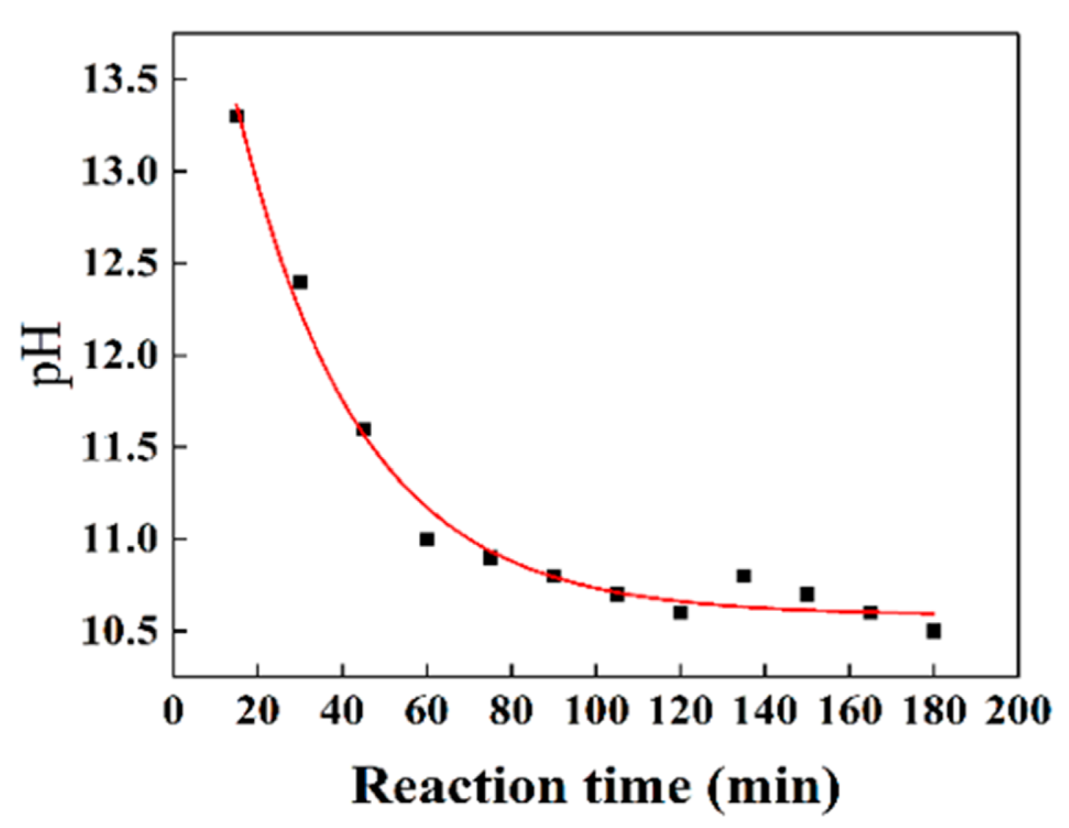
3.1. Preparation Process Analysis

In the Stöber method, the designated silicon source for the preparation of SiO2 is known as tetraethyl orthosilicate (TEOS). This compound undergoes hydrolysis to yield silanol groups (-Si-OH), effectively replacing the ethoxy groups (Si-OR). The pace of this reaction is influenced by the extent of ethoxy group conversion into silanol groups. In the typical Stöber synthesis, a catalyst such as ammonia solution is employed to expedite the hydrolysis and condensation reactions. The presence of OH ions in the ammonia solution enhances their efficacy as nucleophiles. Both hydrolysis and condensation reactions entail nucleophilic substitution, yet the condensation reaction proceeds at a considerably swifter pace compared to hydrolysis. This is attributed to the propensity of silanol groups to release protons more readily than water molecules, resulting in an augmented positive charge density around the silicon atom. Consequently, nucleophilic substitution becomes more favorable. Consequently, silanol monomers display a greater inclination to connect with larger silica clusters, as opposed to other monomers or smaller oligomers.
By manipulating the TMAH content within the silica spheres, three distinct types of silica particles were synthesized, each exhibiting solid, mesoporous, and hollow structures. TMAH, functioning as a catalyst for silica preparation, induces a rapid decline in pH throughout the reaction process, thereby influencing the rates of hydrolysis and condensation of TEOS. During the initial stages of the reaction, both hydrolysis and condensation occur at an accelerated pace, giving rise to a less densely consolidated silica structure that is susceptible to etching. However, in the subsequent stages, these processes decelerate, resulting in the formation of highly condensed silica that resists etching. Figure 2 provides a depiction of the pH variation over time in a reaction solution catalyzed by 2.0 mM TMAH. Within the first hour, the pH of the solution experiences a sharp decline from 13.3 to 11.1, gradually settling at 10.5 over the subsequent two hours. The pH fluctuations exert a direct influence on the hydrolysis and condensation reactions of TEOS facilitated by TMAH, which exhibit heightened reactivity during the initial hour but subsequently decelerate. This deceleration can be attributed to the pronounced drop in pH as the reaction progresses. These distinct stages promote the formation of loosely and tightly aggregated silica gel networks, respectively.

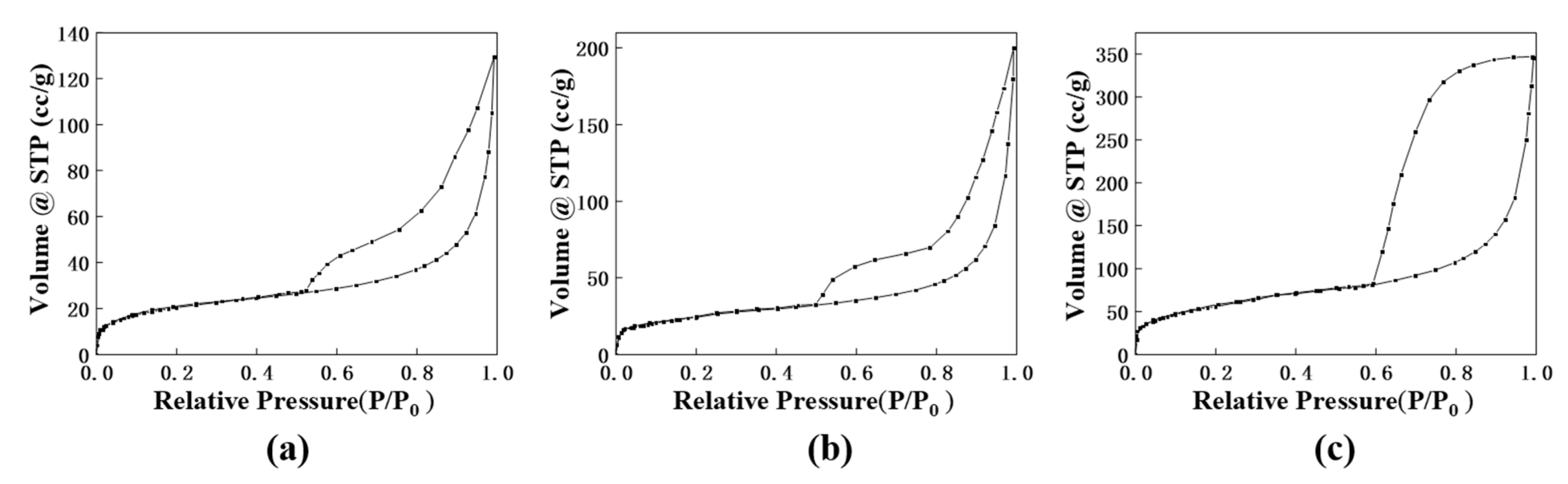
3.2. Morphological Analysis of Silica-Doped Europium Complexes

Through the application of ultrasound and pH adjustment, it became possible to manipulate the concentration and spatial arrangement of tetramethylammonium hydroxide (TMAH) within silica spheres characterized by varying degrees of inner and outer condensation. By subjecting these spheres to alkaline boiling conditions, distinct outcomes were achieved based on the TMAH content. Spheres harboring a greater quantity of TMAH internally underwent etching, resulting in the formation of hollow silica spheres. On the other hand, spheres with a lower and more dispersed concentration of TMAH yielded mesoporous silica spheres through the etching process. Meanwhile, solid silica spheres were obtained from those containing an exceedingly minimal amount of TMAH, even after the etching procedure.
Figure 3a–c showcase transmission electron microscopy (TEM) images of solid, mesoporous, and hollow SiO2 particles, respectively. Additionally, Figure 3d–f present TEM images of solid S@Eu, mesoporous MS@Eu, and hollow SiO2@Eu(TTA)3phen (HS@Eu) complexes, respectively. The synthesized SiO2 particles exhibited an average diameter of 150 nm, with the hollow SiO2 possessing a shell thickness of approximately 27 nm. Notably, the morphologies of the complexes varied depending on their concentrations, as depicted in Figure S1. The images in Figure 3d–f vividly demonstrate the uniform dispersion of flocculent materials on the surface of SiO2 particles. Moreover, it can be observed that the flocculent materials exhibit greater density surrounding MS@Eu and HS@Eu, while fewer free flocculent materials are present near regular SiO2. This reaffirms the adsorption of flocculent materials onto SiO2, as confirmed by Figure 3.
To further investigate the nature of the flocculent material—specifically, whether it corresponds to Eu(TTA)3phen—an energy-dispersive X-ray spectroscopy (EDS) mapping analysis was conducted. Figure 4a–c,f demonstrate the uneven distribution of the elements Eu and S on the mesoporous silica spheres, with the S derived from 2-thenoyltrifluoroacetone. Similarly, EDS mapping analysis was performed on the hollow silica spheres, as presented in Figure 4e–h. The distinct characteristic of the hollow silica spheres is the presence of a lower concentration of Si in the central region and a higher concentration in the outer layer, which is consistent with the findings from the TEM examination. The S and Eu are well dispersed on the outer layer of the silica. Based on the EDS spectrum and TEM results obtained from the hollow silica analysis, it can be concluded that the flocculent material corresponds to Eu(TTA)3phen.

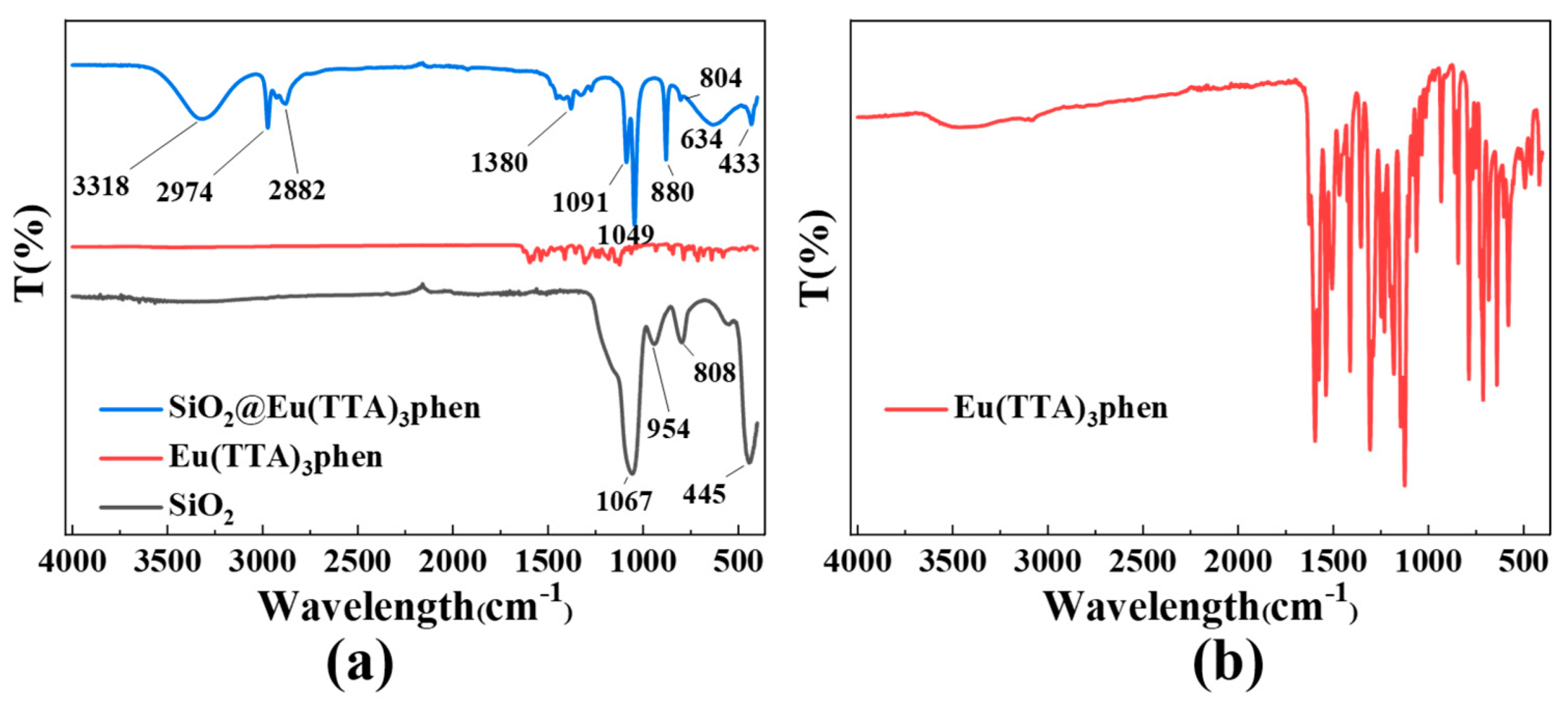
3.3. Analysis of the Binding Mechanism of S@Eu

Figure 5 illustrates the FTIR spectrum. Within the silica infrared spectrum, the peaks at 808 cm−1 and 445 cm−1 correspond to the symmetric stretching vibration of Si-O bonds, while the peak at 954 cm−1 corresponds to the bending vibration of Si-OH bonds. Notably, there is a prominent and broad peak at 1067 cm−1, representing the antisymmetric stretching vibration of Si-O-Si bonds. In the infrared spectrum of Eu(TTA)3phen, numerous small peaks in the range of 500–1700 cm−1 arise from the internal vibrations of Eu(TTA)3phen molecules. For instance, the CF3 stretching vibration occurs within the 1120–1350 cm−1 range, while the phenyl ring exhibits aromatic ring vibration typically observed at 1600–1500 cm−1. Additionally, the carbonyl group generates a carbonyl stretching vibration at 1700–1600 cm−1, and the aromatic amine group induces an amino stretching vibration at 3400–3200 cm−1. Regarding S@Eu, the absence of the peak at 954 cm−1 can be attributed to the reaction between the Si-OH groups on the silica surface and TTA, resulting in the formation of hydrogen bonds. Furthermore, the disappearance of the peak at 808 cm−1 and the emergence of the peaks at 880 cm−1 and 634 cm−1 can be attributed to the formation of Si-O-Eu bonds between Eu(TTA)3phen and the silica surface, along with the formation of Eu-N bonds resulting from the coordination between Eu and phen during the complex formation. Additional peaks observed include 2882 cm−1 and 2974 cm−1, corresponding to the symmetric and antisymmetric stretching vibrations of CH3 in Eu(TTA)3phen, respectively. The peak at 3318 cm−1 represents the stretching vibration of N-H, derived from the residual amino group of ammonia.
The C 1s XPS analysis, depicted in Figure 6b,e, provides valuable insights. It reveals the presence of stable CF3 peaks at approximately 292 eV for both Eu(TTA)3phen and Si@Eu, originating from the TTA ligand. Furthermore, C-O and C=O peaks are observed at 286 eV and 288 eV, respectively. Notably, Si@Eu exhibits an additional peak at 287 eV, which arises from the reaction between the C=O bond in the TTA ligand and the -OH groups on the surface of the silica. This reaction leads to the formation of a C-O-Si bond. The fitting results of the oxygen peak, displayed in Figure 6c,f, indicate that the binding energy of the O-Eu bond in Eu(TTA)3phen is measured at 530 eV. In comparison, S@Eu not only forms bonds with the O atoms in the ligand but also establishes a Si-O-Eu bond with the O atoms on the surface of the silica, resulting in a peak located at 535 eV. The abundance of Si-O-Si bonds indicates that the primary component of S@Eu is still silica. Moreover, infrared analysis confirms the coexistence of both physical adsorption and chemical bonding between the silica and Eu(TTA)3phen.

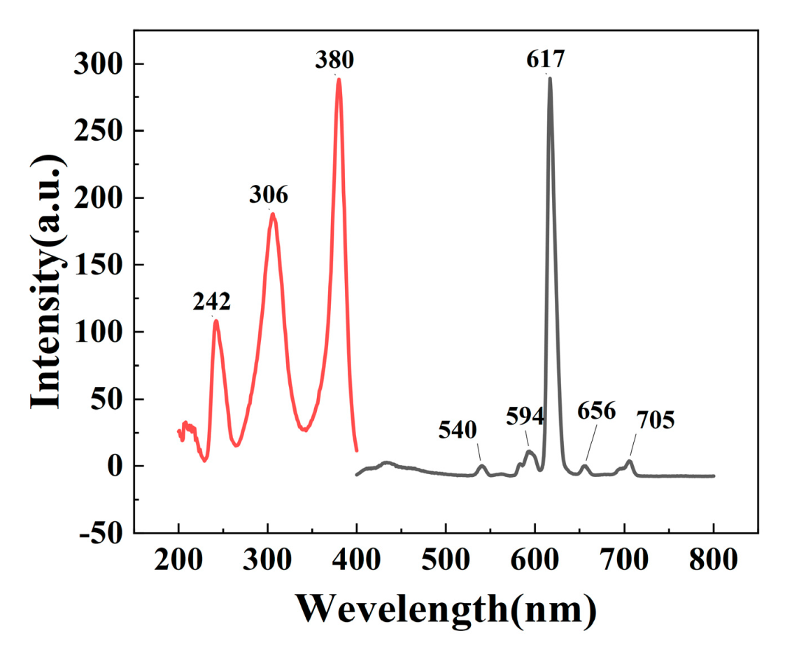
3.4. Analysis of the Fluorescence Properties of S@Eu

The excitation peak is shown in the left panel of Figure 7, with the normal f-f absorption of Eu3+ occurring around 380 nm, the absorption of TTA and phen ligands appearing around 306 nm, and the π-π* transition of TTA at around 240 nm. Fluorescence emission spectra were measured with the strongest excitation at 380 nm, as shown in the right panel of Figure 7, exhibiting a characteristic emission peak at 617 nm, which corresponds to the 5D07F2 (617 nm) transition of Eu3+. The other two peaks at 594 nm and 656 nm correspond to the 5D07F1 and 5D07F3 transitions, respectively. The emission peak at 617 nm is the strongest, while that at 656 nm is the weakest, indicating the characteristic fluorescence emission of Eu3+. The position of the peak is essentially the same as previously reported [59].
Figure 8a presents the fluorescence intensity and lifetime measurements. It can be observed that MS@Eu demonstrates the highest fluorescence intensity, reaching 453. Following that, HS@Eu exhibits an intensity of 312, while S@Eu shows the weakest fluorescence intensity, at 309. The comparison of the fluorescence lifetimes and fitting curves is depicted in Figure 8b, with the corresponding fitting data provided in Table 1. Among the samples, MS@Eu showcases the most favorable fluorescence lifetime performance, with a lifetime of 557 μs. S@Eu exhibits a fluorescence lifetime of 549 μs, while HS@Eu displays a fluorescence lifetime of 460 μs. Furthermore, Figure 8c illustrates the quantum yield data. MS@Eu demonstrates the highest quantum yield, reaching 84.33%. In comparison, HS@Eu and S@Eu exhibit quantum yields of 69.36% and 67.42%, respectively. As a result, it can be concluded that MS@Eu exhibits the most superior overall fluorescence performance among the samples.
The variation in fluorescence intensity among the three structures can be attributed to the specific surface area. The nitrogen adsorption-desorption isotherms for the three structures are presented in Figure 9a–c. Upon analysis, it was found that mesoporous SiO2 possesses the highest BET specific surface area of 261 m2/g, followed by hollow SiO2 with a value of 200 m2/g, and SiO2 with a value of 153 m2/g. This indicates that mesoporous SiO2 exhibits the largest surface area among the three structures. It is noteworthy that MS@Eu, which is composed of mesoporous SiO2, demonstrates the strongest fluorescence intensity. This observation aligns with the expectations based on the test results, as a higher specific surface area generally facilitates enhanced fluorescence intensity.
Mesoporous hollow silica (MHS) was effectively synthesized by manipulating the duration of the ultrasonic treatment and adjusting the pH of the solution, utilizing the principles of mesoporous silica and hollow silica. As depicted in Figure 10b,c, MHS@Eu exhibits a higher fluorescence intensity compared to MS@Eu, albeit with a slightly lower fluorescence lifetime of 481 μs. Additionally, the quantum yield of MHS@Eu was measured to be 85.65%. Overall, MHS showcases superior fluorescence performance, along with a larger specific surface area, as illustrated in the figures.
The cyclic stability test results, as depicted in Figure 11a–c, reveal a significant decline in the fluorescence intensity of Eu(TTA)3phen and S@Eu with increasing centrifugation–sonication cycles. Eventually, the fluorescence intensity of both materials reaches a very low level. However, due to the binding of Eu(TTA)3phen to the surface of silica with a relatively large particle size, S@Eu manages to maintain a relatively favorable fluorescence intensity even after multiple cycles. The fluorescence intensity variations with temperature, as displayed in Figure 11d–f, exhibit distinct patterns. As the temperature rises, the fluorescence intensity of Eu(TTA)3phen experiences a rapid decrease. Conversely, the fluorescence intensity of S@Eu initially increases and then decreases, reaching its peak between 30 °C and 50 °C. In comparison to pure Eu(TTA)3phen, S@Eu demonstrates improved fluorescence intensity at high temperatures, owing to the exceptional heat resistance of silica. The acid–base resistance test outcomes, as demonstrated in Figure 11g–i, indicate poor acid resistance for both Eu(TTA)3phen and S@Eu, with the fluorescence intensity reaching its lowest point at pH 5. However, when compared to Eu(TTA)3phen, S@Eu exhibits better alkali resistance. This can be attributed to the ability of silica to bind to certain −OH groups and mitigate the adverse effects of strong alkaline conditions on the fluorescence performance of Eu(TTA)3phen.

4. Conclusions

Hollow, mesoporous silica was prepared using an improved Stöber method and different etching conditions; subsequently, different structures of S@Eu were prepared. The binding between the silica and rare-earth complexes was confirmed by TEM and EDS tests. The binding mechanism between the two was analyzed through XPS and infrared spectroscopy, revealing that the binding between silica and rare-earth complexes is not only physical adsorption but also involves bonds such as Si-O-Eu and Si-O-C. Fluorescence intensity and lifetime tests showed that the fluorescence performance of silica-doped europium complexes was effectively improved, with mesoporous silica showing the best performance. Based on the BET test, it was found that specific surface area was the main factor affecting the fluorescence performance of the products. MHS@Eu was prepared, which further improved the fluorescence intensity. Finally, the cycling stability, high-temperature resistance, and acid–base resistance of Eu(TTA)3phen and S@Eu were compared, with S@Eu showing excellent resistance to high temperatures and bases, as well as excellent cycling stability. This research has broad potential applications in fluorescence probes and other fields.

Supplementary Materials

The following supporting information can be downloaded at: https://www.mdpi.com/article/10.3390/ma16134501/s1, Figure S1 Different concentrations of Eu(TTA)3phen: (a) 0.00001 mol/L; (b) 0.0001 mol/L; (c) 0.001 mol/L; (d) 0.01 mol/L.

Author Contributions

Methodology, Z.W.; validation, Z.W. and X.H.; investigation, Y.Y. and C.G.; original draft preparation, Z.W.; writing—review and editing, W.W., J.T., Y.W. and X.G.; supervision, W.W.; project administration, J.T. and Y.W. All authors have read and agreed to the published version of the manuscript.

Funding

This work was supported by (1) the Natural Scientific Foundation of China (Grant Nos. 51603109, 41806112, 51273096, 51473082), (2) the State Key Project of International Cooperation Research (2017YFE0108300, 2016YFE0110800), (3) the Shandong Double-Hundred Project, (4) the Program for Introducing Talents of Discipline to Universities (“111” plan), and (5) the High-Level Discipline Program of Shandong Province of China.

Data Availability Statement

The data that support the findings of this study are available from the corresponding author upon reasonable request.

Conflicts of Interest

The authors declare no conflict of interest.

References

  1. Das, A.; Mohanty, S.; Kumar, R.; Kuanr, B.K. Tailoring the Design of a Lanthanide Complex/Magnetic Ferrite Nanocomposite for Efficient Photoluminescence and Magnetic Hyperthermia Performance. ACS Appl. Mater. Interfaces 2020, 12, 42016–42029. [Google Scholar] [CrossRef] [PubMed]
  2. Xie, X.; Tan, X.; Yu, Y.; Li, Y.; Wang, P.; Liang, Y.; Yan, Y. Effectively auto-regulated adsorption and recovery of rare earth elements via an engineered E. coli. J. Hazard. Mater. 2022, 424, 127642. [Google Scholar] [CrossRef] [PubMed]
  3. Yin, W.; Liu, L.; Zhang, H.; Tang, S.; Chi, R. A facile solvent-free and one-step route to prepare amino-phosphonic acid functionalized hollow mesoporous silica nanospheres for efficient Gd(III) removal. J. Clean. Prod. 2020, 243, 118688. [Google Scholar] [CrossRef]
  4. Yang, J.; Feng, M.; Zhang, K.; Chen, Z.; Xu, R.; Khan, A.; Li, Y.; Xie, J.; Liu, L.; Song, F.; et al. All-Inorganic Functional Phosphor–Glass Composites by Light Curing Induced 3D Printing for Next-Generation Modular Lighting Devices. Adv. Opt. Mater. 2022, 10, 2201110. [Google Scholar] [CrossRef]
  5. Zhang, T.; Kitagawa, Y.; Moriake, R.; Ferreira da Rosa, P.P.; Islam, M.J.; Yoneda, T.; Inokuma, Y.; Fushimi, K.; Hasegawa, Y. Hybrid Eu(III) Coordination Luminophore Standing on Two Legs on Silica Nanoparticles for Enhanced Luminescence. Chemistry 2021, 27, 14438–14443. [Google Scholar] [CrossRef]
  6. Zhu, M.; Zhang, H.; Ran, G.; Mangel, D.N.; Yao, Y.; Zhang, R.; Tan, J.; Zhang, W.; Song, J.; Sessler, J.L.; et al. Metal Modulation: An Easy-to-Implement Tactic for Tuning Lanthanide Phototheranostics. J. Am. Chem. Soc. 2021, 143, 7541–7552. [Google Scholar] [CrossRef]
  7. Szpikowska-Sroka, B.; Pawlik, N.; Goryczka, T.; Pisarski, W.A. Effect of the initial reagents concentration on final crystals size and luminescence properties of PbF2:Eu3+ phosphors. J. Alloys Compd. 2018, 730, 150–160. [Google Scholar] [CrossRef]
  8. De Azevedo, L.A.; Gamonal, A.; Maier-Queiroz, R.; Silva, C.S.; Ferro, J.N.S.; Oliveira, P.d.A.S.C.; Barreto, E.O.; da Luz, L.L.; Alves Júnior, S. Multi-stimuli-responsive luminescent MCM48 hybrid for advanced anti-counterfeiting applications. J. Mater. Chem. C 2021, 9, 9261–9270. [Google Scholar] [CrossRef]
  9. Ansari, A.A. Photochemical studies of monodispersed YPO4: Eu microspheres: The role of surface modification on structural and luminescence properties. J. Photochem. Photobiol. A Chem. 2017, 343, 126–132. [Google Scholar] [CrossRef]
  10. Patten, J.T.; Byrne, R.H. Assessment of Fe(III) and Eu(III) complexation by silicate in aqueous solutions. Geochim. Cosmochim. Acta 2017, 202, 361–373. [Google Scholar] [CrossRef]
  11. Novotný, M.; Vondráček, M.; Marešová, E.; Fitl, P.; Bulíř, J.; Pokorný, P.; Havlová, Š.; Abdellaoui, N.; Pereira, A.; Hubík, P.; et al. Optical and structural properties of ZnO:Eu thin films grown by pulsed laser deposition. Appl. Surf. Sci. 2019, 476, 271–275. [Google Scholar] [CrossRef]
  12. Li, J.; Wu, Y.; Cao, J.; Wei, Z.; Guo, Y.; Wang, Q.; Peng, Q.; Li, Y.; He, X. Excellent flexibility of high-temperature-treated SiO2-TiO2 hybrid fibres and their enhanced luminescence with Eu3+ doping. Ceram. Int. 2017, 43, 12710–12717. [Google Scholar] [CrossRef]
  13. Liu, S.; Cui, H.; Liu, M.; Chen, J.; Wen, M.; Li, S.; Wang, W.; Li, J.-G.; Sun, X. Spherical red-emitting X1-Y2SiO5:Eu and α-Y2Si2O7:Eu phosphors with high color purity: The evolution of morphology, phase and photoluminescence upon annealing. Ceram. Int. 2022, 48, 8641–8652. [Google Scholar] [CrossRef]
  14. Mason, H.E.; Begg, J.D.; Maxwell, R.S.; Kersting, A.B.; Zavarin, M. A novel solid-state NMR method for the investigation of trivalent lanthanide sorption on amorphous silica at low surface loadings. Environ. Sci. Process. Impacts 2016, 18, 802–809. [Google Scholar] [CrossRef]
  15. Armelao, L.; Belli Dell’Amico, D.; Bellucci, L.; Bottaro, G.; Labella, L.; Marchetti, F.; Samaritani, S. Smart Grafting of Lanthanides onto Silica via N,N-Dialkylcarbamato Complexes. Inorg. Chem. 2016, 55, 939–947. [Google Scholar] [CrossRef]
  16. Xu, X.; Zhang, X.; Hu, C.; Li, W.; Lei, B.; Liu, Y.; Zhuang, J. Construction of NaYF(4):Eu@carbon dots nanocomposites for multifunctional applications. J. Colloid. Interface Sci. 2019, 543, 156–163. [Google Scholar] [CrossRef]
  17. Lin, C.; Song, Y.; Gao, F.; Zhang, H.; Sheng, Y.; Zheng, K.; Shi, Z.; Xu, X.; Zou, H. Synthesis and luminescence properties of Eu(III)-doped silica nanorods based on the sol–gel process. J. Sol-Gel Sci. Technol. 2013, 69, 536–543. [Google Scholar] [CrossRef]
  18. Yang, S.; Chen, L.; Zhou, X.; Sun, P.; Fu, L.; You, Y.; Xu, M.; You, Z.; Kai, G.; He, C. Tumor-targeted biodegradable multifunctional nanoparticles for cancer theranostics. Chem. Eng. J. 2019, 378, 122171. [Google Scholar] [CrossRef]
  19. Dalmis, R.; Birlik, I.; Ak Azem, N.F.; Celik, E. Structurally colored silica photonic crystal coatings modified by Ce or Eu rare-earth dopants. Colloids Surf. A Physicochem. Eng. Asp. 2020, 603, 125138. [Google Scholar] [CrossRef]
  20. Qiao, Y.; Chen, H.; Lin, Y.; Yang, Z.; Cheng, X.; Huang, J. Photoluminescent Lanthanide-Doped Silica Nanotubes: Sol−Gel Transcription from Functional Template. J. Phys. Chem. C 2011, 115, 7323–7330. [Google Scholar] [CrossRef]
  21. Cheng, C.-A.; Chen, W.; Zhang, L.; Wu, H.H.; Zink, J.I. A Responsive Mesoporous Silica Nanoparticle Platform for Magnetic Resonance Imaging-Guided High-Intensity Focused Ultrasound-Stimulated Cargo Delivery with Controllable Location, Time, and Dose. J. Am. Chem. Soc. 2019, 141, 17670–17684. [Google Scholar] [CrossRef] [PubMed]
  22. Wang, W.; Li, Z.; Yao, P.; Li, J.; Chen, F.; Liu, Y. Sink-in/pile-up formation and crack nucleation mechanisms of high purity fused silica and soda-lime silica glass during nanoindentation experiments. Ceram. Int. 2020, 46, 24698–24709. [Google Scholar] [CrossRef]
  23. Garcia, E.; Arnold, C.; Hermier, J.P.; D’Amico, M. Correction: Gold plasmonic enhanced luminescence of silica encapsulated semiconductor hetero-nanoplatelets. Nanoscale Adv. 2021, 3, 5968. [Google Scholar] [CrossRef] [PubMed]
  24. Yang, F.; Zhao, H.; Wang, W.; Wang, L.; Zhang, L.; Liu, T.; Sheng, J.; Zhu, S.; He, D.; Lin, L.; et al. Atomic origins of the strong metal-support interaction in silica supported catalysts. Chem. Sci. 2021, 12, 12651–12660. [Google Scholar] [CrossRef] [PubMed]
  25. Lu, Y.; Liu, Z.; Li, X.; Jiangyin, X.; Djati Utomo, H. Development of water-based thermal insulation paints using silica aerogel made from incineration bottom ash. Energy Build. 2022, 259, 111866. [Google Scholar] [CrossRef]
  26. Wang, J.; Chen, T.; Xu, B.; Chen, Y. Fabrication and Characterization of Porous Core–Shell Graphene/SiO2 Nanocomposites for the Removal of Cationic Neutral Red Dye. Appl. Sci. 2020, 10, 8529. [Google Scholar] [CrossRef]
  27. Alftessi, S.A.; Othman, M.H.D.; Adam, M.R.; Farag, T.M.; Ismail, A.F.; Rahman, M.A.; Jaafar, J.; Habib, M.A.; Raji, Y.O.; Hubadillah, S.K. Novel silica sand hollow fibre ceramic membrane for oily wastewater treatment. J. Environ. Chem. Eng. 2021, 9, 104975. [Google Scholar] [CrossRef]
  28. Kong, S.; Wu, S.; Tang, Z.; Guo, B. Hydrogen bond-containing oligomer as a facile interfacial mediator in rubber/silica composites. Compos. Commun. 2023, 37, 101413. [Google Scholar] [CrossRef]
  29. Shams, M.; Alam, I.; Chowdhury, I. Interactions of nanoscale plastics with natural organic matter and silica surfaces using a quartz crystal microbalance. Water Res. 2021, 197, 117066. [Google Scholar] [CrossRef]
  30. Wang, M.; Kickhoefer, V.A.; Lan, E.H.; Dunn, B.S.; Rome, L.H.; Mahendra, S. Vault nanocapsule-mediated biomimetic silicification for efficient and robust immobilization of proteins in silica composites. Chem. Eng. J. 2021, 418, 129406. [Google Scholar] [CrossRef]
  31. Dahal, R.H.; Nguyen, T.M.; Shim, D.S.; Kim, J.Y.; Lee, J.; Kim, J. Development of Multifunctional Cosmetic Cream Using Bioactive Materials from Streptomyces sp. T65 with Synthesized Mesoporous Silica Particles SBA-15. Antioxidants 2020, 9, 278. [Google Scholar] [CrossRef] [Green Version]
  32. Yu, J.; Kim, Y.H.; Kim, H.M.; Oh, J.M.; Kim, Y.R.; Choi, S.J. Determination of the fate and biological responses of food additive silica particles in commercial foods. Food Chem. 2020, 331, 127304. [Google Scholar] [CrossRef]
  33. Errington, E.; Guo, M.; Heng, J.Y.Y. Synthetic amorphous silica: Environmental impacts of current industry and the benefit of biomass-derived silica. Green. Chem. 2023, 25, 4244–4259. [Google Scholar] [CrossRef]
  34. Porrang, S.; Davaran, S.; Rahemi, N.; Allahyari, S.; Mostafavi, E. How Advancing are Mesoporous Silica Nanoparticles? A Comprehensive Review of the Literature. Int. J. Nanomed. 2022, 17, 1803–1827. [Google Scholar] [CrossRef]
  35. Melnikov, P.V.; Naumova, A.O.; Alexandrovskaya, A.Y.; Zaitsev, N.K. Optimizing Production Conditions for a Composite Optical Oxygen Sensor Using Mesoporous SiO2. Nanotechnologies Russ. 2019, 13, 602–608. [Google Scholar] [CrossRef]
  36. Kumar, S.; Malik, M.M.; Purohit, R. Synthesis Methods of Mesoporous Silica Materials. Mater. Today Proc. 2017, 4, 350–357. [Google Scholar] [CrossRef]
  37. Sharma, J.; Polizos, G. Hollow Silica Particles: Recent Progress and Future Perspectives. Nanomaterials 2020, 10, 1599. [Google Scholar] [CrossRef]
  38. Li, K.; Yang, C.; Yu, H.; Xiao, T.; Guan, W.; Ding, P.; Yin, H.; Cohen Stuart, M.A.; Wang, J.; Zhou, S. Coordination-Enhanced Synthesis for Hollow Mesoporous Silica Nanoreactors. Chem. Mater. 2020, 32, 2086–2096. [Google Scholar] [CrossRef]
  39. Allouche, J.; Le Beulze, A.; Dupin, J.-C.; Ledeuil, J.-B.; Blanc, S.; Gonbeau, D. Hybrid spiropyran–silica nanoparticles with a core-shell structure: Sol–gel synthesis and photochromic properties. J. Mater. Chem. 2010, 20, 9370–9378. [Google Scholar] [CrossRef]
  40. Chen, C.; Zhang, L.; Li, M.; Tian, A.; Wang, C.; Fu, S. Controlling morphology and particle size of hollow poly(styrene-divinylbenzene) microspheres fabricated by template-based method. J. Saudi Chem. Soc. 2018, 22, 644–653. [Google Scholar] [CrossRef]
  41. Zhao, C.; Ge, Z.; Jiang, Z.; Yan, S.; Shu, J.; Wang, M.; Ge, X. Study on the morphological regulation mechanism of hollow silica microsphere prepared via emulsion droplet template. Chin. Chem. Lett. 2023, 34, 107499. [Google Scholar] [CrossRef]
  42. Ye, L.; Li, L.; Wang, X.; Zhang, Y.; Yan, L. Template-free synthesis of uniform hollow silica nanoparticles for controllable antireflection coatings. Ceram. Int. 2020, 46, 7453–7458. [Google Scholar] [CrossRef]
  43. Xu, J.; Chen, Z.; Ren, D.; Xiang, X.; Chen, N.; Li, X.; Ye, Z.; Chen, Q.; Ma, S. Preparation of hollow nanoparticles with controllable diameter by one-step controlled etching of microporous silica particles using an ammonia-based etchant. Colloids Surf. A Physicochem. Eng. Asp. 2020, 592, 124579. [Google Scholar] [CrossRef]
  44. Yuan, N.; Sun, Y.-N.; Liu, Z.-W.; Han, B.-H. Facile synthesis of diamine-functionalized hollow mesoporous silica sphere with self-templating method. J. Porous Mater. 2018, 25, 1715–1721. [Google Scholar] [CrossRef]
  45. Watanabe, K.; Kuroda, K.; Nagao, D. Polyethylenimine-assisted synthesis of hollow silica spheres without shape deformation. Mater. Chem. Phys. 2021, 262, 124267. [Google Scholar] [CrossRef]
  46. Wu, X.; Nan, Z. Degradation of rhodamine B by a novel Fe3O4/SiO2 double-mesoporous-shelled hollow spheres through photo-Fenton process. Mater. Chem. Phys. 2019, 227, 302–312. [Google Scholar] [CrossRef]
  47. Dong, Y.; Wang, E.; Yu, L.; Wang, R.; Zhu, Y.; Fu, Y.; Ni, Q. Self-templated route to synthesis bowl-like and deflated balloon-like hollow silica spheres. Mater. Lett. 2017, 206, 150–153. [Google Scholar] [CrossRef]
  48. Hashimoto, T.; Tagaya, M.; Kataoka, T.; Chatani, S.; Inui, M.; Higa, Y.; Motozuka, S. Synthesis and photoluminescence properties of the Eu(III)-containing silica nanoparticles via a mechanochemical solid-state reaction between SiO2 and EuCl3·6H2O. Adv. Powder Technol. 2020, 31, 3650–3656. [Google Scholar] [CrossRef]
  49. Guillaume, C.; Frieiro, J.L.; Blázquez, O.; Labbé, C.; López-Vidrier, J.; Garrido, B.; Hernández, S.; Liu, B.; Khomenkova, L.; Frilay, C.; et al. Influence of post annealing treatments on the luminescence of rare earth ions in ZnO: Tb, Eu/Si heterojunction. Appl. Surf. Sci. 2021, 556, 149754. [Google Scholar] [CrossRef]
  50. Liang, Y.; Noh, H.M.; Park, S.H.; Choi, B.C.; Jeong, J.H. Colloidal GdVO4:Eu3+ @SiO2 nanocrystals for highly selective and sensitive detection of Cu2+ ions. Appl. Surf. Sci. 2018, 433, 381–387. [Google Scholar] [CrossRef]
  51. Yan, X.; Wang, Y.; Li, B.; Huang, Z.; Gao, Z.; Mao, X.; Wang, W.; Zhu, Z.; Kipper, M.J.; Huang, L.; et al. Polyacrylonitrile fluorescent nanofibers for selective and reversible copper detection in aqueous solutions. Appl. Surf. Sci. 2022, 602, 154302. [Google Scholar] [CrossRef]
  52. Alcaraz, L.; Isasi, J. Synthesis and study of Y0.9Ln0.1VO4 nanophosphors and Y0.9Ln0.1VO4@SiO2 luminescent nanocomposites with Ln=Eu, Dy, Er. Ceram. Int. 2017, 43, 5311–5318. [Google Scholar] [CrossRef]
  53. Chen, P.; Mao, Y.; Hou, S.; Chen, Y.; Liu, X.; Lou, Y.; Chen, A.; Yang, L.; Li, J.; Dai, N. Effects of In2O3 nanoparticles doping on the photoluminescent properties of Eu2+/Eu3+ ions in silica glasses. Ceram. Int. 2019, 45, 233–238. [Google Scholar] [CrossRef]
  54. De Pablos-Martín, A.; Oberleiter, B.; Thieme, C.; Rainer, T.; Höche, T. Nanostructure investigation of Eu3+-containing porous silica glasses: Influence of pore size and sintering conditions. Ceram. Int. 2018, 44, 14625–14630. [Google Scholar] [CrossRef]
  55. Jia, M.; Wen, J.; Pan, X.; Zhang, L.; Yuan, J.; Huang, Y.; Zhang, X.; He, L.; Pang, F.; Wang, T. Flexible Scintillation Silica Fiber with Engineered Nanocrystals for Remote Real-Time X-ray Detection. ACS Appl. Mater. Interfaces 2022, 14, 1362–1372. [Google Scholar] [CrossRef]
  56. He, Y.; Liu, J.; Sung, S.-J.; Chang, C.-H. Downshifting and antireflective thin films for solar module power enhancement. Mater. Des. 2021, 201, 109454. [Google Scholar] [CrossRef]
  57. Li, H.; Kang, J.; Yang, J.; Wu, B. Fabrication of Aunanoparticle@mSiO2@Y2O3:Eu nanocomposites with enhanced fluorescence. J. Alloys Compd. 2016, 673, 283–288. [Google Scholar] [CrossRef]
  58. Han, Y.; Guo, Z.; Teng, S.; Xia, H.; Wang, D.; Han, M.-Y.; Yang, W. Rationalized Fabrication of Structure-Tailored Multishelled Hollow Silica Spheres. Chem. Mater. 2019, 31, 7470–7477. [Google Scholar] [CrossRef]
  59. Liu, L.; Lu, Y.L.; He, L.; Zhang, W.; Yang, C.; Liu, Y.D.; Zhang, L.Q.; Jin, R.G. Novel Europium-Complex/Nitrile-Butadiene Rubber Composites. Adv. Funct. Mater. 2005, 15, 309–314. [Google Scholar] [CrossRef]
Figure 1. Preparation process of SiO2@Eu(TTA)3phen with different structures.
Materials 16 04501 g001
Figure 2. Time-dependent curve of solution pH during the preparation of SiO2.
Materials 16 04501 g002
Figure 3. TEM images of silica with different morphologies: (a) silica; (b) mesoporous silica; (c) hollow silica; (d) S@Eu; (e) MS@Eu; (f) HS@Eu.
Materials 16 04501 g003
Figure 4. EDS mapping images of different morphologies of silica coated with Eu (TTA)3phen: (a) TEM image of MS@Eu; (b) Si elemental mapping of MS@Eu; (c) Eu elemental mapping of MS@Eu; (d) S elemental mapping of MS@Eu; (e) TEM image of HS@Eu; (f) Si elemental mapping of HS@Eu; (g) Eu elemental mapping of HS@Eu; (h) S elemental mapping of HS@Eu.
Materials 16 04501 g004
Figure 5. (a) FTIR of Eu(TTA)3phen, SiO2, and MS@Eu; (b) FTIR of Eu(TTA)3phen.
Materials 16 04501 g005
Figure 6. XPS images of silica with different morphologies: (a) XPS for Eu(TTA)3phen; (b) XPS of C1s for Eu(TTA)3phen; (c) XPS of O1s for Eu(TTA)3phen; (d) XPS for S@Eu; (e) XPS of C1s for S@Eu; (f) XPS of O1s for S@Eu.
Materials 16 04501 g006
Figure 7. Fluorescence excitation and fluorescence emission diagram of Eu(TTA)3phen.
Materials 16 04501 g007
Figure 8. (a) Fluorescence intensity; (b) fluorescence lifetime fitting curve; (c) quantum yield.
Materials 16 04501 g008
Figure 9. N2 adsorption-desorption isotherms: (a) SiO2; (b) hollow SiO2; (c) mesoporous SiO2.
Materials 16 04501 g009
Figure 10. (a) TEM images of HMS@Eu; (b) fluorescence intensity of HMS@Eu and MS@Eu; (c) fluorescence lifetimes of HMS@Eu and MS@Eu; (d) N2 adsorption-desorption isotherms of MHS.
Materials 16 04501 g010
Figure 11. (a) Fluorescence intensity of Eu(TTA)3phen varies with the number of cycles. (b) Fluorescence intensity of S@Eu varies with the number of cycles. (c) Cyclic stability. (d) Fluorescence intensity of Eu(TTA)3phen varies with temperature. (e) Fluorescence intensity of S@Eu varies with temperature. (f) High-temperature resistance. (g) Fluorescence intensity of Eu(TTA)3phen varies with pH. (h) Fluorescence intensity of S@Eu varies with pH. (i) Acid–alkali resistance.
Materials 16 04501 g011
Table 1. Fluorescence lifetime fitting parameters.
Sampley0A1t1A2t2τ
HS@Eu6.04 × 10−41.23460,387.780.10950,775.77460 μs
Ms@Eu4.71 × 10−40.51391,854.010.77712,052.92557 μs
S@Eu5.47 × 10−40.85436,486.490.47730,546.66549 μs
Disclaimer/Publisher’s Note: The statements, opinions and data contained in all publications are solely those of the individual author(s) and contributor(s) and not of MDPI and/or the editor(s). MDPI and/or the editor(s) disclaim responsibility for any injury to people or property resulting from any ideas, methods, instructions or products referred to in the content.

