
Experimental Study on Shear Behavior of Non-Stirrup Ultra-High Performance Concrete Beams


Abstract
1. Introduction
2. Experimental Program
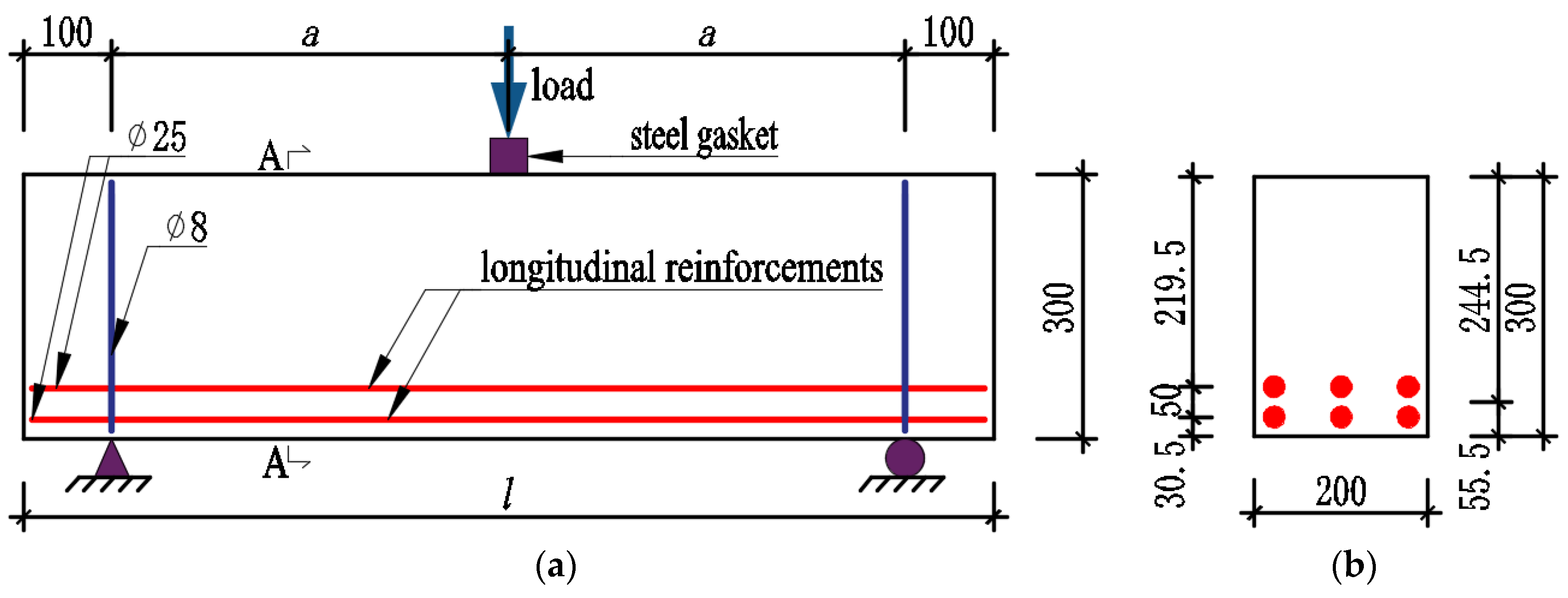
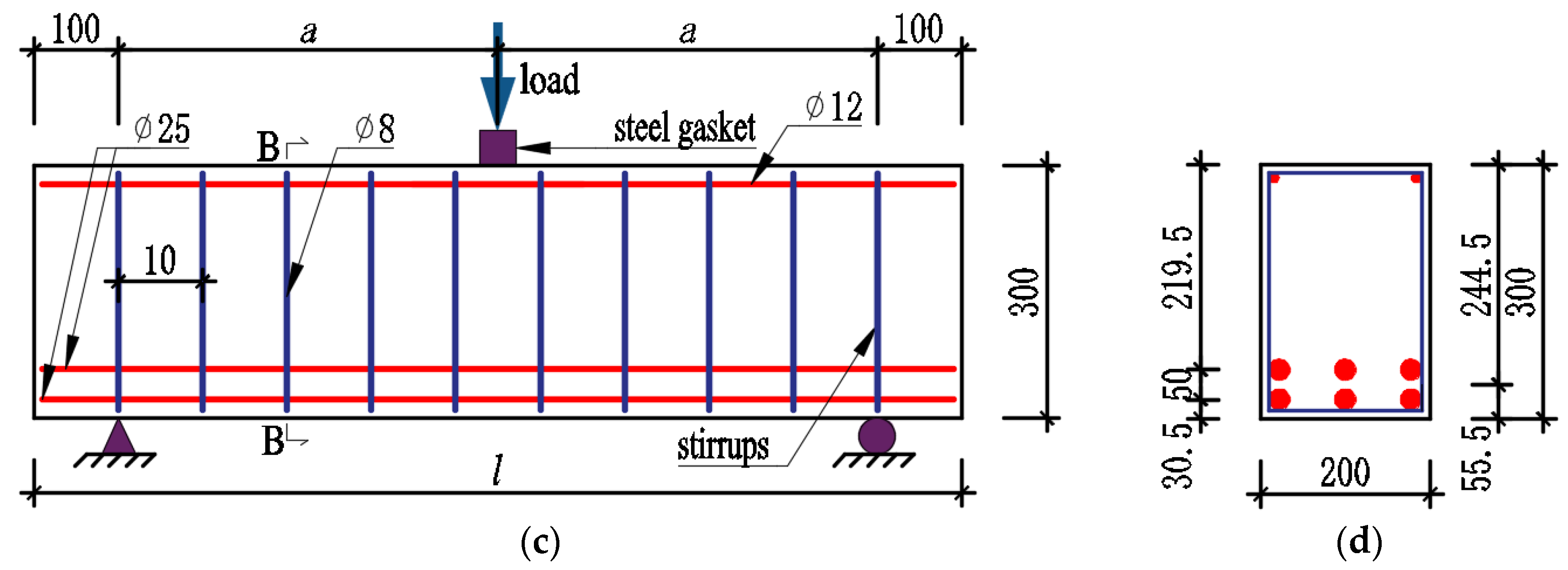
2.1. Specimen Description
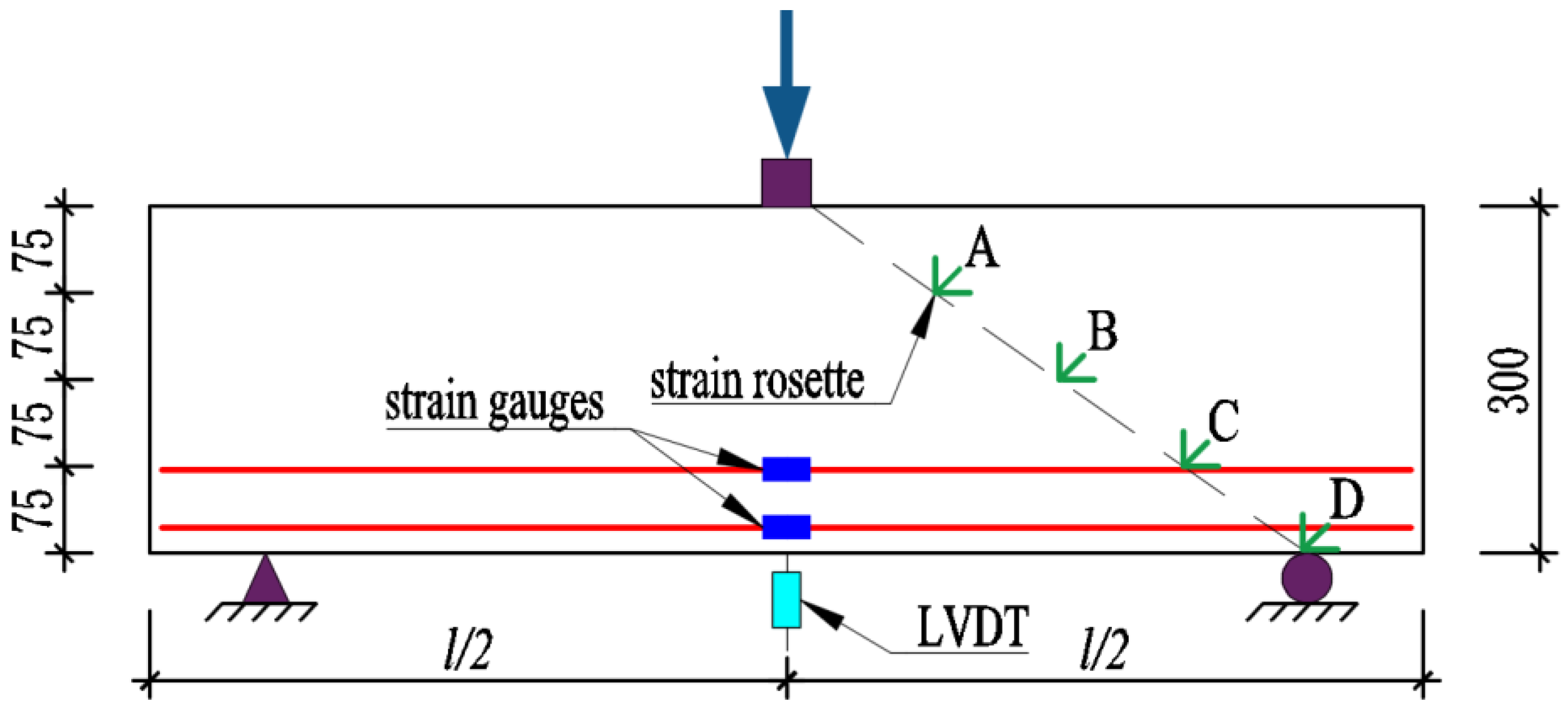
2.2. Test Process and Instrumentation
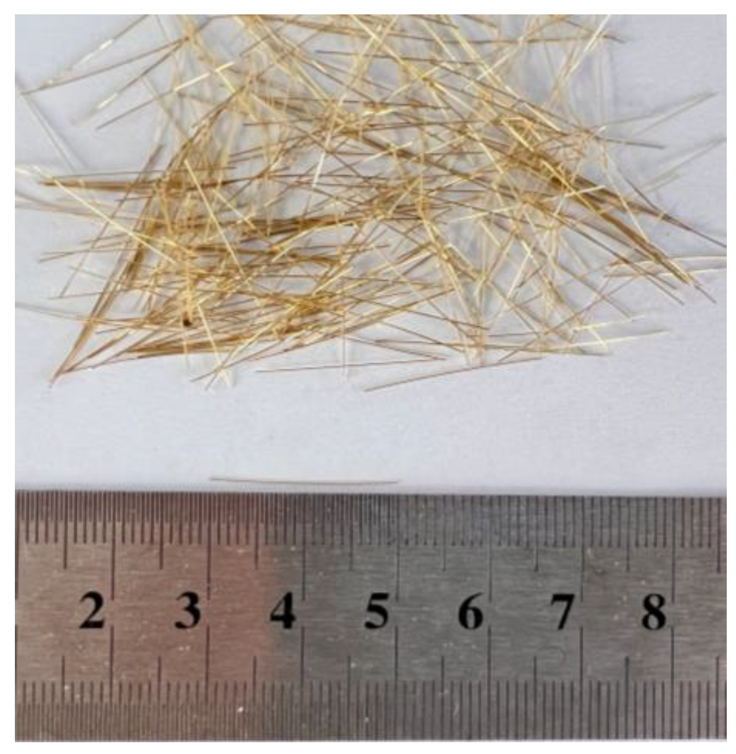
2.3. Material Properties
3. Experimental Results and Discussion
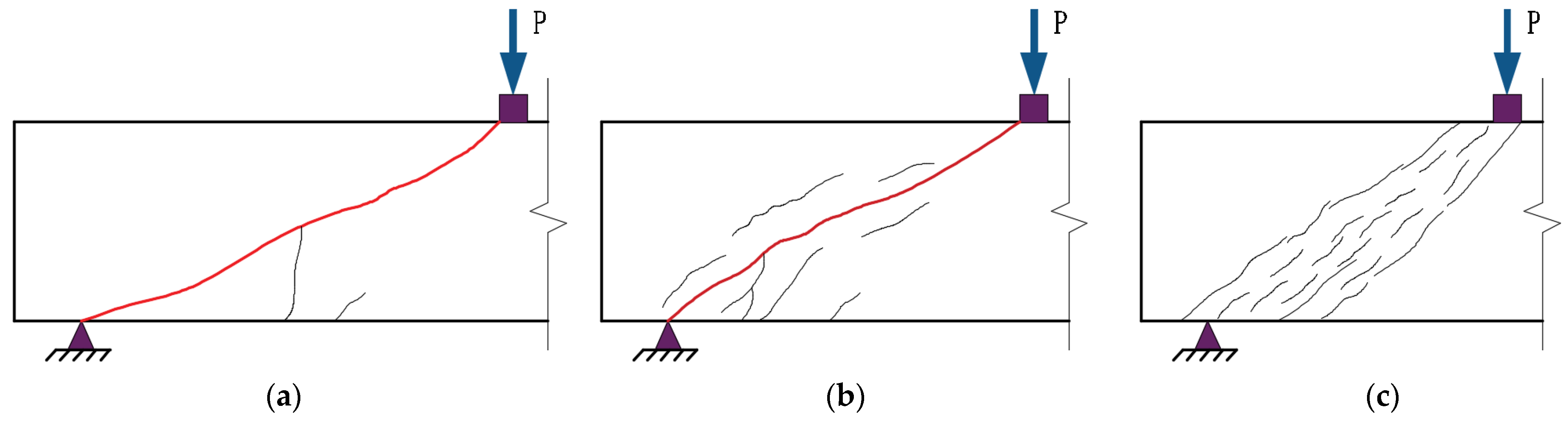
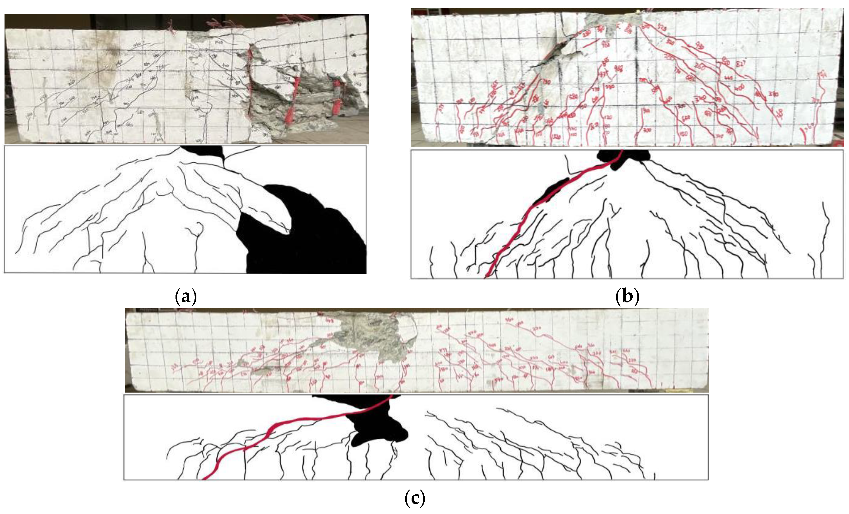
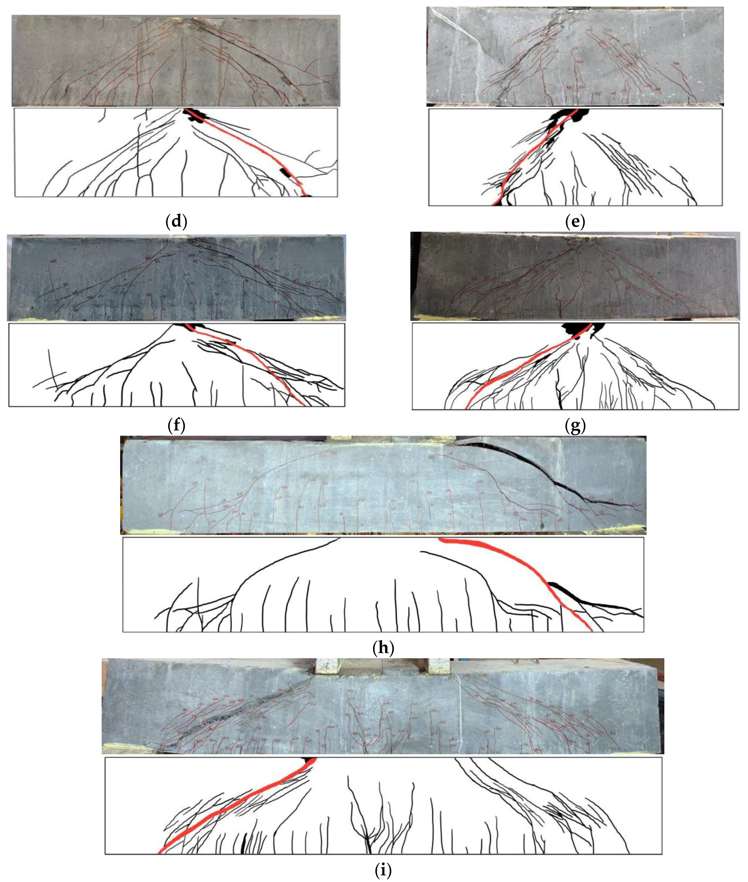
3.1. Failure Modes and Crack Patterns
3.1.1. Effect of Shear Span-to-Depth Ratio on Failure Modes and Crack Patterns
3.1.2. Effect of Steel Fibers on Failure Modes and Crack Patterns
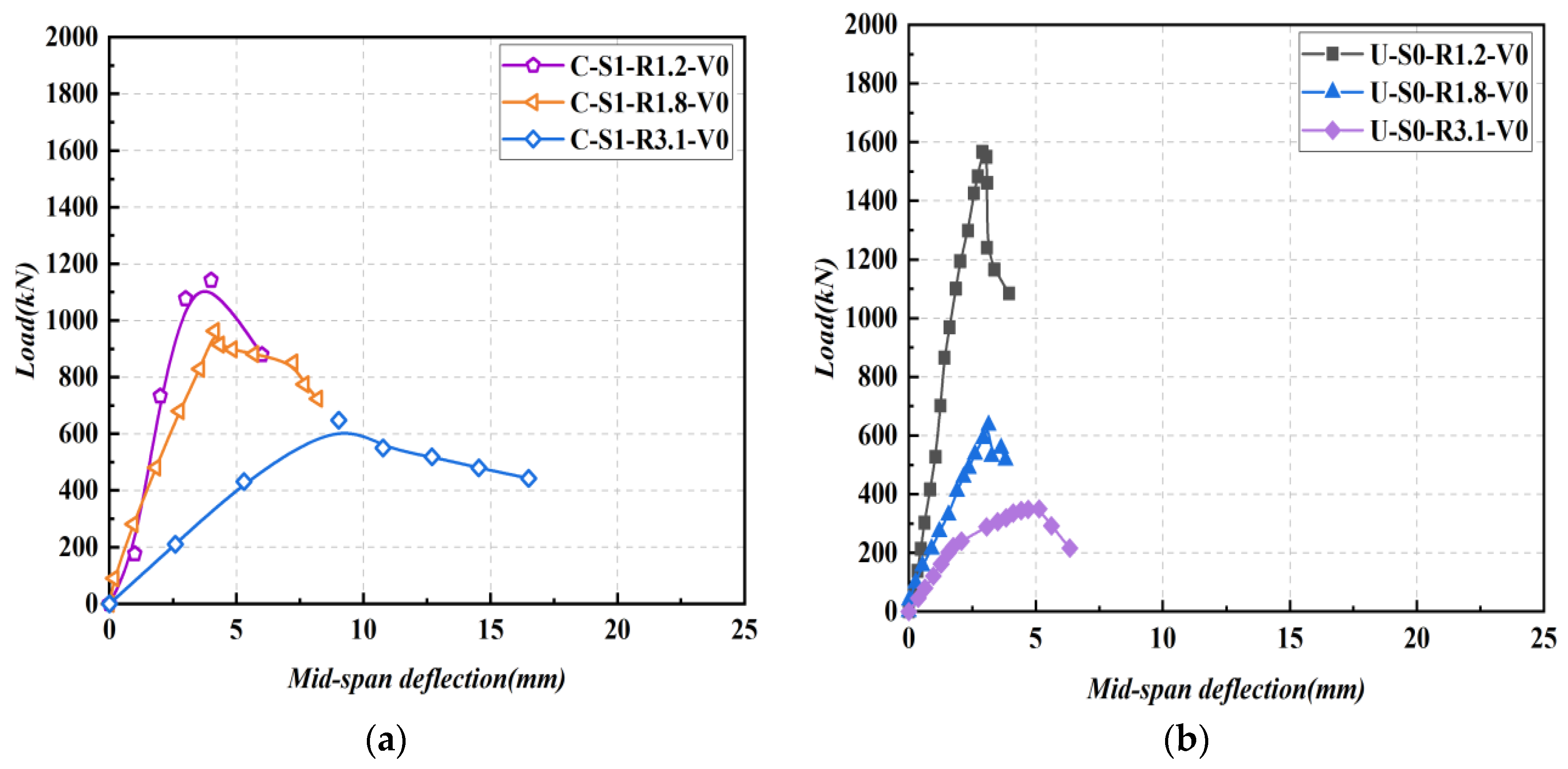
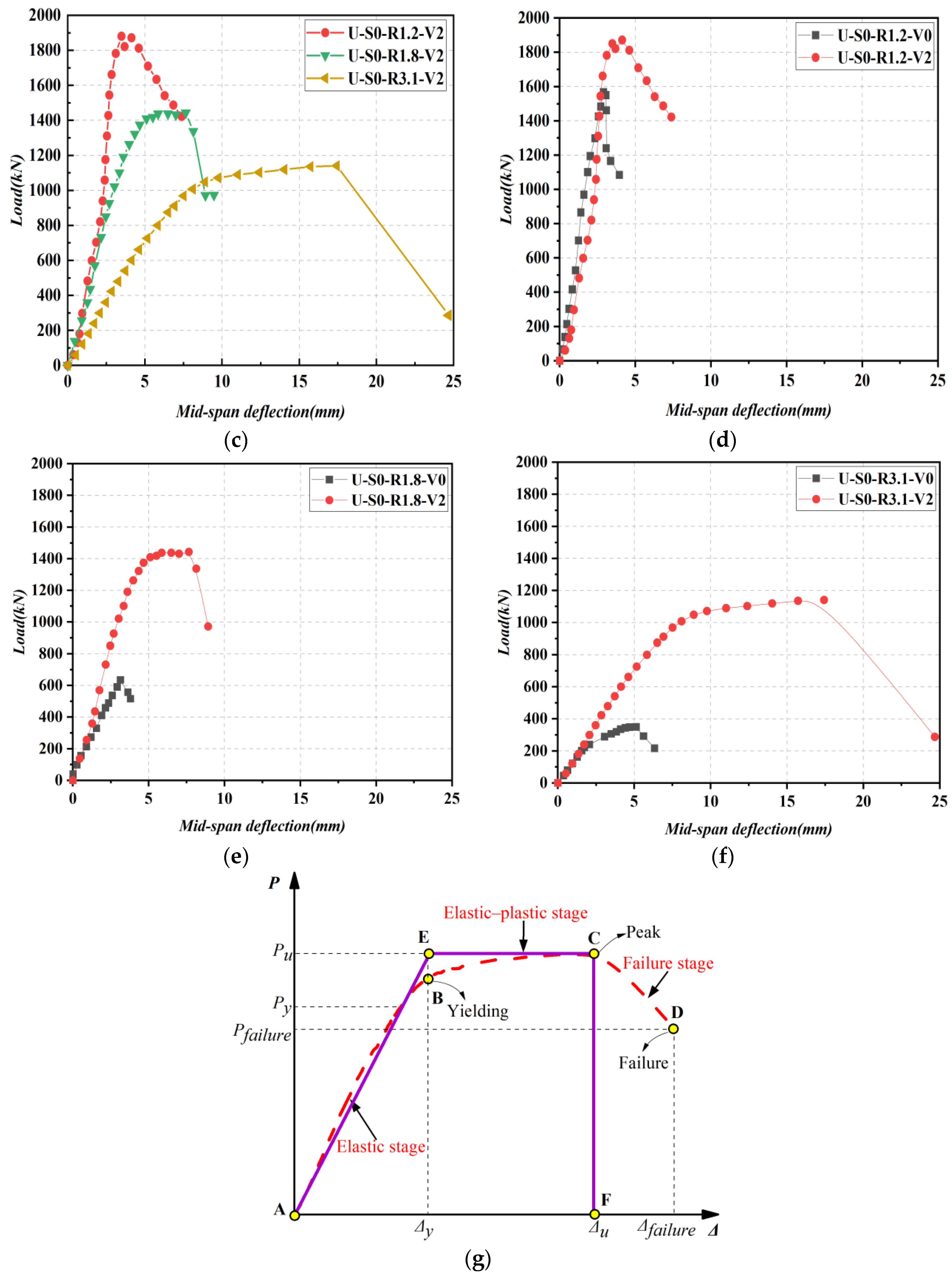
3.2. Load-Displacement Relationships
3.3. Strain Response
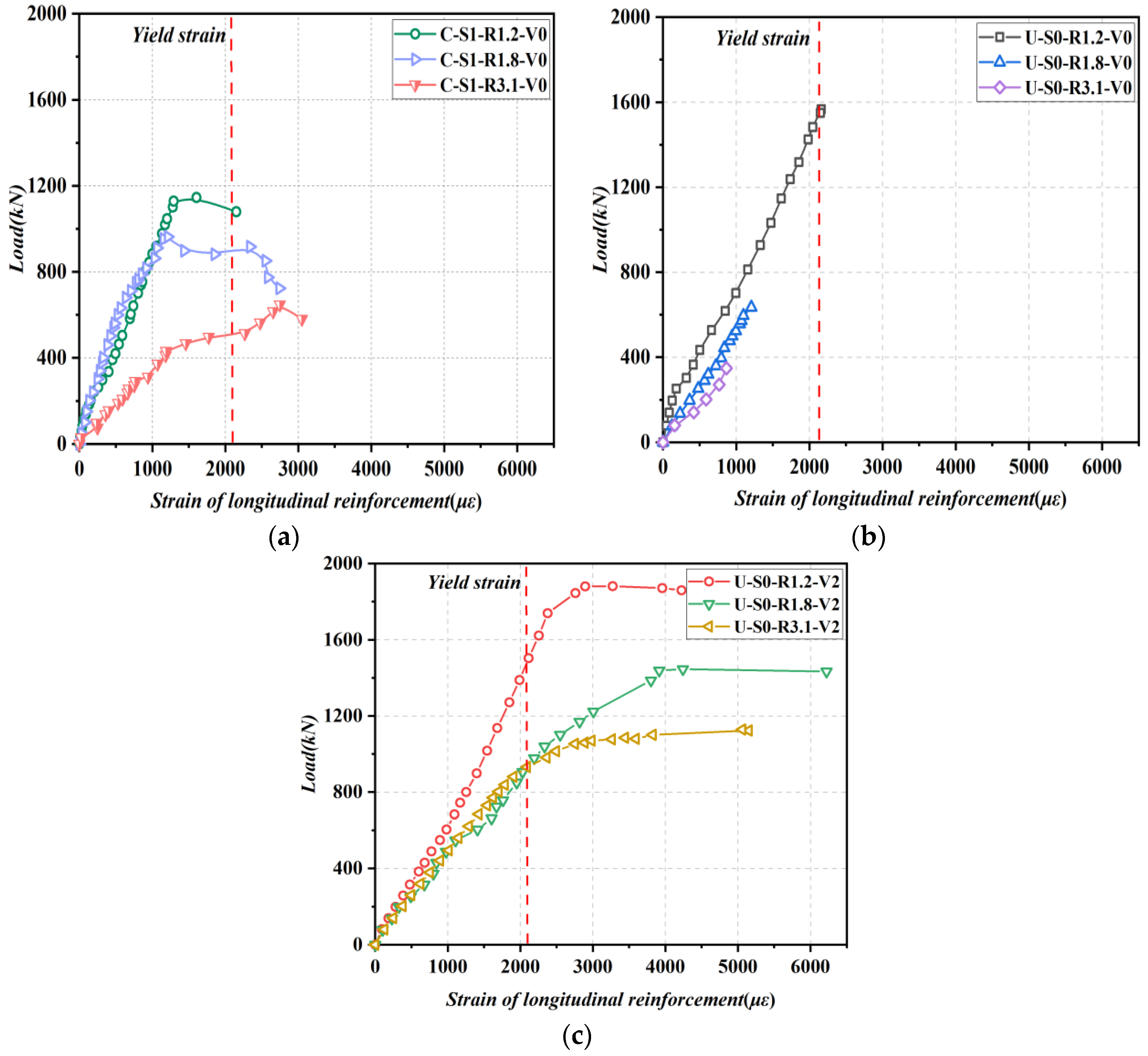
3.3.1. Strain Response of Longitudinal Reinforcements
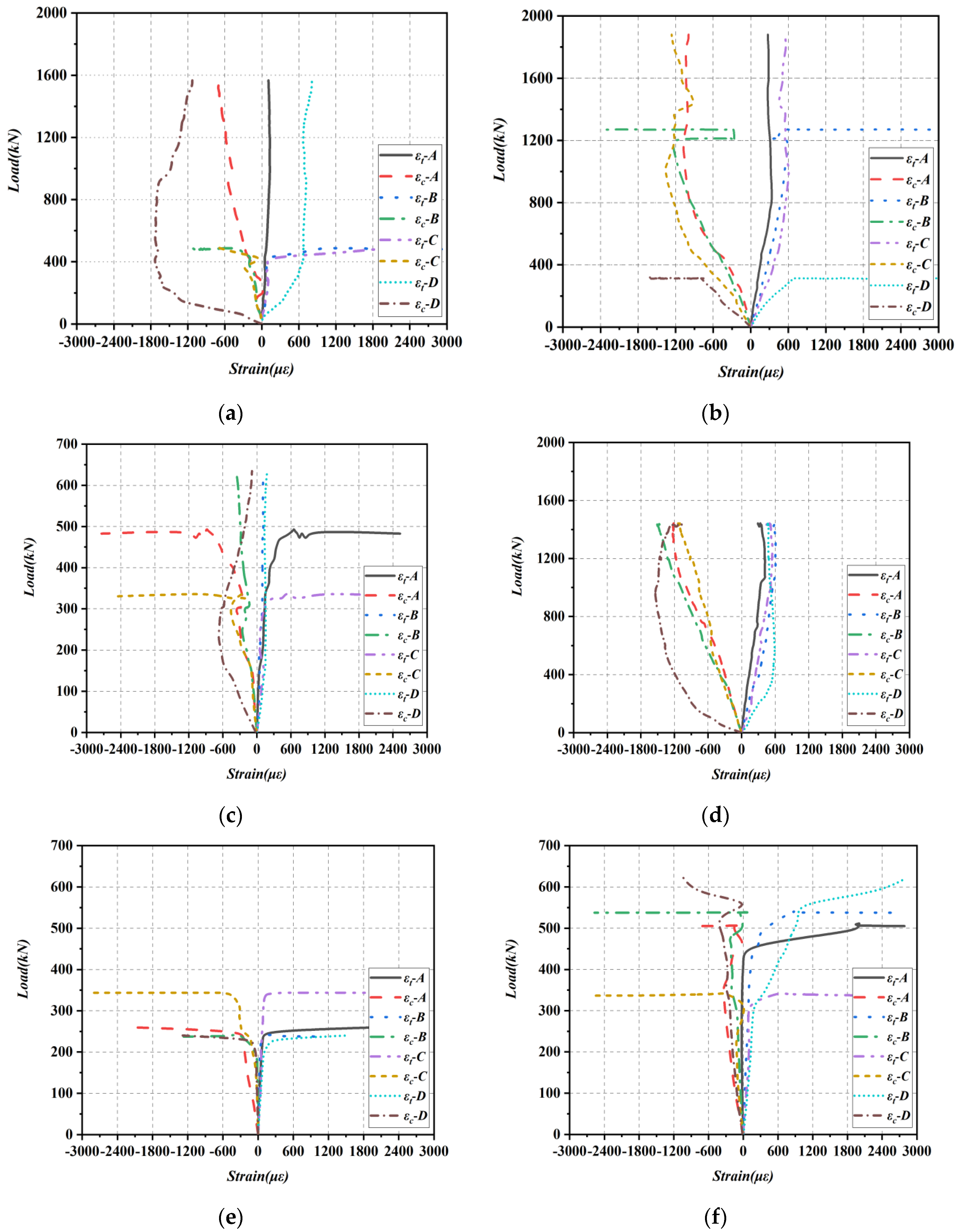
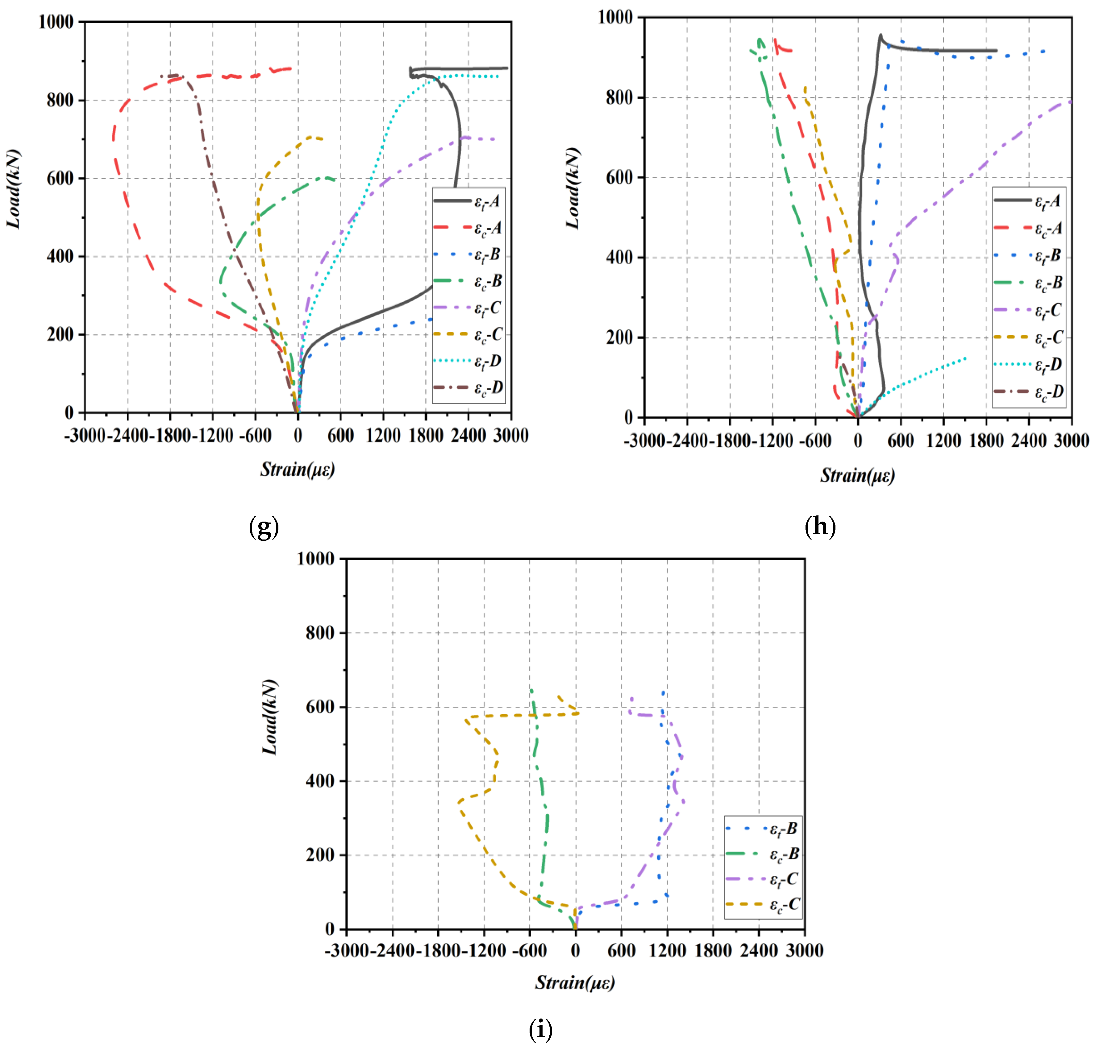
3.3.2. Strain Response of Concrete Diagonal Sections
3.4. Post-Cracking Shear Resistance
3.5. The Ultimate Shear Strengths
4. Shear Design Recommendations for UHPC Beams
4.1. French Standard Formulae
4.2. PCI-2021 Formulae
4.3. Xu’s Formulae
4.4. Comparison of Calculation Results
5. Conclusions
- (1)
- The failure modes of all nine test beams were shear failures. For SR−NC beams, specimen C-S1-R1.2-V0 failed by diagonal compression, while specimens C-S1-R1.8-V0 and C-S1-R3.1-V0 exhibited shear compression failure. Non-stirrup UHPC beams primarily failed due to shear compression, with the only exception being specimen U-S0-R3.1-V0, which failed in diagonal tensile mode. Steel fibers are a crucial factor affecting the failure mode of non-stirrup UHPC beams and can effectively improve the cracking strength of the beams. Steel fibers play a critical role in influencing the failure mode of non-stirrup UHPC beams and can effectively enhance the cracking strength of the beams.
- (2)
- The stiffness of a beam, which is reflected in the slope of its elastic stage, can be impacted by the . The elastic-plastic stage of the curve is impacted by steel fibers, leading to improved ductility of the beam up to a maximum ductility coefficient of 2.75.
- (3)
- The longitudinal reinforcements were fully utilized in NSR−UHPC−2 beams bearing shear, which had yielded before reaching ultimate shear strength. The principal strains in the shear-bending section increased linearly with the increase in the load before the cracks crossed strain rosettes and increased from the loading point toward the support, where the principal compressive strains near the support varied more significantly.
- (4)
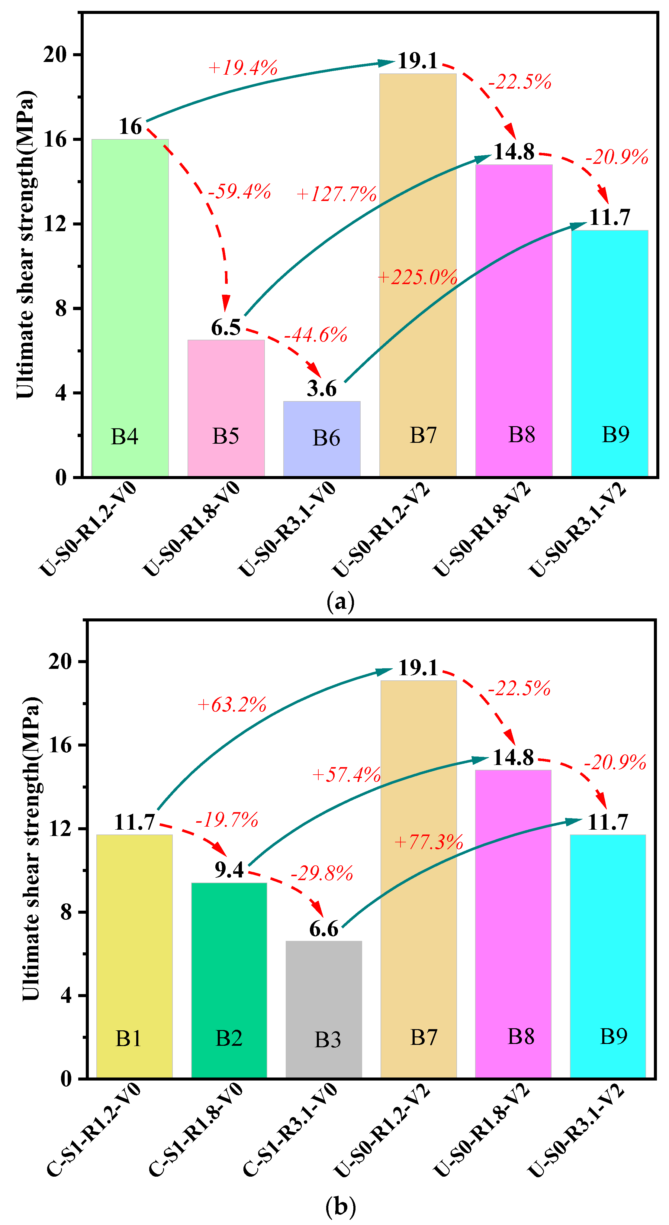
- The increase in the resulted in a decrease in ultimate shear strength, with NSR−UHPC−0 beams experiencing a reduction of over 40% in ultimate shear strength as this ratio increased. At the same time, the decrease in ultimate shear strength for both NSR−UHPC−2 beams and SR−NC beams was between 20% to 30% as the increased.
- (5)
- Compared with NSR−UHPC−0 beams (B4, B5 and B6), the ultimate shear strength of NSR−UHPC−2 beams (B7, B8 and B9) increased by 19.4%, 127.7% and 225.0%, respectively. NSR−UHPC−2 beams demonstrated excellent post-cracking shear resistance and ultimate shear strength. Hence, it was considered feasible to eliminate stirrups in UHPC beams with sufficient shear capacity.
- (6)
- French standard formulae and the PCI-2021 formulae can be used for shear design NSR−UHPC−2 beams. Xu’s formulae are suitable for all UHPC beams in this paper when a reduction factor is taken into account. The accuracy and applicability of the reduction factor need to be verified by more tests.
Author Contributions
Funding
Institutional Review Board Statement
Informed Consent Statement
Data Availability Statement
Acknowledgments
Conflicts of Interest
References
- Hung, C.C.; Chen, Y.T.; Yen, C.H. Workability, fiber distribution, and mechanical properties of UHPC with hooked end steel macro-fibers. Constr. Build. Mater. 2020, 260, 119944. [Google Scholar] [CrossRef]
- Graybeal, B.; Tanesi, J. Durability of an ultrahigh-performance concrete. J. Mater. Civ. Eng. 2007, 19, 848–854. [Google Scholar] [CrossRef]
- Xu, X.B.; Yu, Y.; Jin, Z.Q.; Zhu, C.A. Review on Effects of Microstructure and Mechanical Properties of Ultra-High Performance Concrete by Curing Regimes. Bull. Chin. Ceram. Soc. 2021, 40, 2856–2870. (In Chinese) [Google Scholar]
- Liu, L.M.; Fang, Z.; Liu, F.C.; Xiao, M. Experimental study on the shrinkage and creep of UHPC in indoor environments. China J. Highw. Transp. 2021, 34, 35–44. (In Chinese) [Google Scholar]
- Olivito, R.S.; Zuccarello, F.A. An experimental study on the tensile strength of steel fiber reinforced concrete. Compos. Part B 2009, 41, 246–255. [Google Scholar] [CrossRef]
- Binard, J. UHPC: A game-changing material for PCI bridge producers. PCI J. 2017, 62, 34–46. [Google Scholar] [CrossRef]
- Cuenca, E.; Postolachi, V.; Ferrara, L. Cellulose nanofibers to improve the mechanical and durability performance of self-healing Ultra-High Performance Concretes exposed to aggressive waters. Constr. Build. Mater. 2023, 374, 130785. [Google Scholar] [CrossRef]
- Cuenca, E.; Lo Monte, F.; Moro, M.; Schiona, A.; Ferrara, L. Effects of autogenous and stimulated self-healing on durability and mechanical performance of UHPFRC: Validation of tailored test method through multi-performance healing-induced recovery indices. Sustainability 2021, 13, 11386. [Google Scholar] [CrossRef]
- Fang, Z.C.; Fang, H.Z.; Huang, J.X.; Jiang, H.B.; Chen, G.F. Static behavior of grouped stud shear connectors in steel–precast UHPC composite structures containing thin full-depth slabs. Eng. Struct. 2022, 252, 113484. [Google Scholar] [CrossRef]
- Zou, Y.; Zheng, K.D.; Zhou, Z.X.; Zhang, Z.Y.; Guo, J.C.; Jiang, J.L. Experimental study on flexural behavior of hollow steel-UHPC composite bridge deck. Eng. Struct. 2023, 274, 115087. [Google Scholar] [CrossRef]
- Fang, Z.C.; Fang, H.Z.; Li, P.J.; Jiang, H.B.; Chen, G.F. Interfacial shear and flexural performances of steel–precast UHPC composite beams: Full-depth slabs with studs vs. demountable slabs with bolts. Eng. Struct. 2022, 260, 114230. [Google Scholar] [CrossRef]
- Fang, S.; Zhang, S.; Cao, Z.; Zhao, G.; Fang, Z.; Ma, Y.; Jiang, H. Effects of stud aspect ratio and cover thickness on push-out performance of thin full-depth precast UHPC slabs with grouped short studs: Experimental evaluation and design considerations. J. Build. Eng. 2023, 67, 105910. [Google Scholar] [CrossRef]
- Fang, Z.C.; Hu, L.K.; Jiang, H.B.; Fang, S.; Zhao, G.F.; Ma, Y.H. Shear performance of high-strength friction-grip bolted shear connector in prefabricated steel–UHPC composite beams: Finite element modelling and parametric study. Case Stud. Constr. Mater. 2023, 18, e01860. [Google Scholar] [CrossRef]
- Voo, Y.L.; Foster, S.J.; Voo, C.C. Ultrahigh-performance concrete segmental bridge technology: Toward sustainable bridge construction. J. Bridge Eng. 2015, 20, B5014001. [Google Scholar] [CrossRef]
- Feng, Z.; Li, C.X.; Ke, L.; Yoo, D.Y. Experimental and numerical investigations on flexural performance of ultra-high-performance concrete (UHPC) beams with wet joints. In Structures; Elsevier: Amsterdam, The Netherlands, 2022; pp. 199–213. [Google Scholar]
- Feng, J.H.; Hu, Z.B.; Jiang, H.B.; Hu, J.H.; Qiu, Y.T. Influence of RPC grouting materials on shear behavior of wet joints in PCSBs with confining stress. Constr. Build. Mater. 2021, 299, 123993. [Google Scholar] [CrossRef]
- Jiang, H.B.; Huang, C.W.; Mei, G.Y.; Gao, X.J.; Tian, Y.Q.; Sun, X.D. Experimental and numerical investigations on direct shear performance of UHPC dry joints. Eng. Struct. 2023, 283, 115872. [Google Scholar] [CrossRef]
- Reineck, K.H.; Kuchma, D.A.; Kim, K.S.; Marx, S. Shear database for reinforced concrete members without shear reinforcement. Struct. J. 2003, 100, 240–249. [Google Scholar]
- Collins, M.P.; Bentz, E.C.; Sherwood, E.G. Where is shear reinforcement required? Review of research results and design procedures. Struct. J. 2008, 105, 590–600. [Google Scholar]
- Jabbar, A.M.; Mohammed, D.H.; Hamood, M.J. Using Fibers instead of Stirrups for Shear in Ultra-High Performance Concrete T-beams. Aust. J. Struct. Eng. 2023, 24, 36–49. [Google Scholar] [CrossRef]
- Wu, Y.F.; Hu, B. Shear strength components in reinforced concrete members. J. Struct. Eng. 2017, 143, 04017092. [Google Scholar] [CrossRef]
- Shao, X.D.; Li, F.Y.; Qiu, M.H.; Liu, Q.W. Influential and comparative research on the effects of steel fiber properties on the axial tensile and bending tensile properties of UHPC. China J. Highw. Transp. 2020, 33, 51–64. (In Chinese) [Google Scholar]
- Yu, R.; Fan, D.Q.; Sun, M.J.; Zhang, J.J.; Shui, Z.H.; Hou, D.S.; Wang, D.S.; Wang, X.P.; Feng, Y. Effects of steel fibre content and 3D network on performance of ultra-high performance concrete. J. Chin. Ceram. Soc. 2021, 49, 2313–2321. (In Chinese) [Google Scholar]
- Abbas, Y.M.; Iqbal Khan, M. Influence of fiber properties on shear failure of steel fiber reinforced beams without web reinforcement: ANN modeling. Lat. Am. J. Solids Struct. 2016, 13, 1483–1498. [Google Scholar] [CrossRef]
- Amin, A.; Gilbert, R.I. Instantaneous crack width calculation for steel fiber-reinforced concrete flexural members. ACI Struct. J. 2018, 115, 535–543. [Google Scholar] [CrossRef]
- Blasón, S.; Poveda, E.; Ruiz, G.; Cifuentes, H.; Canteli, A.F. Twofold normalization of the cyclic creep curve of plain and steel-fiber reinforced concrete and its application to predict fatigue failure. Int. J. Fatigue 2019, 120, 215–227. [Google Scholar] [CrossRef]
- Kang, S.T.; Kim, J.K. Investigation on the flexural behavior of UHPCC considering the effect of fiber orientation distribution. Constr. Build. Mater. 2012, 28, 57–65. [Google Scholar] [CrossRef]
- Yoo, D.Y.; Kim, S.; Kim, J.J.; Chun, B. An experimental study on pullout and tensile behavior of ultra-high-performance concrete reinforced with various steel fibers. Constr. Build. Mater. 2019, 206, 46–61. [Google Scholar] [CrossRef]
- Qi, J.N.; Wu, Z.M.; Ma, Z.J.; Wang, J.Q. Pullout behavior of straight and hooked-end steel fibers in UHPC matrix with various embedded angles. Constr. Build. Mater. 2018, 191, 764–774. [Google Scholar] [CrossRef]
- Lee, S.H.; Kim, S.; Yoo, D.Y. Hybrid effects of steel fiber and carbon nanotube on self-sensing capability of ultra-high-performance concrete. Constr. Build. Mater. 2018, 185, 530–544. [Google Scholar] [CrossRef]
- Ding, Y.; You, Z.; Jalali, S. The composite effect of steel fibres and stirrups on the shear behaviour of beams using self-consolidating concrete. Eng. Struct. 2011, 33, 107–117. [Google Scholar] [CrossRef]
- Meng, W.; Khayat, K.H. Effect of hybrid fibers on fresh properties, mechanical properties, and autogenous shrinkage of cost-effective UHPC. J. Mater. Civ. Eng. 2018, 30, 04018030. [Google Scholar] [CrossRef]
- Singh, B.; Jain, K. An appraisal of steel fibers as minimum shear reinforcement in concrete beams. ACI Struct. J. 2014, 111, 1191–1202. [Google Scholar] [CrossRef]
- Xiao, Y. Quantifying Ultra-High Performance Concrete Flexural System Mechanical Response; University of Central Florida: Orlando, FL, USA, 2014. [Google Scholar]
- Mahdi, A.M. Impact of Failure-surface Parameters of Concrete Damage Plasticity Model on the Behavior of Reinforced Ultra-high Performance Concrete Beams. Period. Polytech. Civ. Eng. 2023, 67, 495–504. [Google Scholar] [CrossRef]
- Yang, J.; Chen, B.; Su, J.; Xu, G.; Zhang, D.; Zhou, J. Effects of fibers on the mechanical properties of UHPC: A review. J. Traffic Transp. Eng. Engl. Ed. 2022, 9, 363–387. [Google Scholar] [CrossRef]
- Lee, J.W.; Joh, C.; Choi, E.; Kwak, I.; Kim, B.S. Estimation of Shear Behavior of Ultra High Performance Concrete I Girder without Shear Stirrups. Key Eng. Mater. 2013, 525, 557–560. [Google Scholar] [CrossRef]
- Voo, Y.L.; Foster, S.J.; Gilbert, R.I. Shear strength of fiber reinforced reactive powder concrete prestressed girders without stirrups. J. Adv. Concr. Technol. 2006, 4, 123–132. [Google Scholar] [CrossRef]
- Jiang, H.B.; Hu, Z.B.; Cao, Z.P.; Gao, X.J.; Tian, Y.Q.; Sun, X.D. Experimental and numerical study on shear performance of externally prestressed precast UHPC segmental beams without stirrups. In Structures; Elsevier: Amsterdam, The Netherlands, 2022; pp. 1134–1153. [Google Scholar]
- Voo, Y.L.; Poon, W.K.; Foster, S.J. Shear strength of steel fiber-reinforced ultrahigh-performance concrete beams without stirrups. J. Struct. Eng. 2010, 136, 1393–1400. [Google Scholar] [CrossRef]
- Yang, I.H.; Joh, C.; Lee, J.W.; Kim, B.S. An experimental study on shear behavior of steel fiber-reinforced ultra high performance concrete beams. KSCE J. Civ. Environ. Eng. Res. 2012, 32, 55–64. [Google Scholar]
- Ahmad, S.; Bahij, S.; Al-Osta, M.; Adekunle, S.; Al-Dulaijan, S. Shear behavior of ultra-high-performance concrete beams reinforced with high-strength steel bars. ACI Struct. J. 2019, 116, 3–14. [Google Scholar] [CrossRef]
- El-Sayed, A.K.; El-Salakawy, E.F.; Benmokrane, B. Shear strength of fibre-reinforced polymer reinforced concrete deep beams without web reinforcement. Can. J. Civ. Eng. 2012, 39, 546–555. [Google Scholar] [CrossRef]
- Bertram, G. Experimental investigations on the shear behavior of pretensioned beams made of UHPC with and without web openings. Bauingenieur 2015, 90, 444–455. [Google Scholar] [CrossRef]
- Zagon, R.; Matthys, S.; Kiss, Z. Shear behaviour of SFR-UHPC I-shaped beams. Constr. Build. Mater. 2016, 124, 258–268. [Google Scholar] [CrossRef]
- Baby, F.; Marchand, P.; Toutlemonde, F. Shear behavior of ultrahigh performance fiber-reinforced concrete beams. I: Experimental investigation. J. Struct. Eng. 2014, 140, 04013111. [Google Scholar] [CrossRef]
- Pourbaba, M.; Joghataie, A.; Mirmiran, A. Shear behavior of ultra-high performance concrete. Constr. Build. Mater. 2018, 183, 554–564. [Google Scholar] [CrossRef]
- Bahij, S.; Adekunle, S.K.; Al-Osta, M.; Ahmad, S.; Al-Dulaijan, S.U.; Rahman, M.K. Numerical investigation of the shear behavior of reinforced ultra-high-performance concrete beams. Struct. Concr. 2018, 19, 305–317. [Google Scholar] [CrossRef]
- Byun, N.; Lee, J.; Han, S.; Kang, Y. Analysis Study on Shear Behavior of Prestressed Ultra-High Performance I-Girder. J. Korean Soc. Hazard Mitig. 2017, 17, 235–245. [Google Scholar] [CrossRef]
- Feng, J.H.; Li, P.S.; Wu, J.P.; Jiang, H.B.; Tian, Y.Q.; Sun, X.D. Shear behavior of externally prestressed UHPC beams without stirrups. Case Stud. Constr. Mater. 2023, 18, e01766. [Google Scholar] [CrossRef]
- NF P18–470; Concrete—Ultra-High Performance Fibre-Reinforced Concrete—Specifications, Performance, Production and Conformity. French Standardization Association: Paris, France, 2016.
- NF P18–710; National Addition to Eurocode 2—Design of Concrete Structures: Specific Rules for Ultra-High Performance Fibre-Reinforced Concrete (UHPFRC). French Standardization Association: Paris, France, 2016.
- Tadros, M.; Lawler, J.; El-Khier, M.A.; Gee, D.; Kurt, A.; Lucier, G.; Wagner, E. Implementation of Ultra-High-Performance Concrete in Long-Span Precast Pretensioned Elements for Concrete Buildings and Bridges; Precast/Prestressed Concrete Institute (PCI): Chicago, IL, USA, 2021. [Google Scholar]
- Xu, H.B.; Deng, Z.C.; Chen, C.S.; Chen, X.W. Experimental study on shear strength of ultra-high performance fiber reinforced concrete beams. China Civ. Eng. J. 2014, 47, 91–97. (In Chinese) [Google Scholar]
- Gusella, F. Effect of the plastic rotation randomness on the moment redistribution in reinforced concrete structures. Eng. Struct. 2022, 252, 113652. [Google Scholar] [CrossRef]
- Luo, D.; Li, B. Moment redistribution capacity of continuous RC beams with High-Strength steel reinforcement. In Structures; Elsevier: Amsterdam, The Netherlands, 2023; pp. 13–24. [Google Scholar]


| NO. | Specimens | Series | Concrete Type | Stirrup Ratio | l (mm) | a (mm) | Volume Content of Steel Fiber | |
|---|---|---|---|---|---|---|---|---|
| B1 | C-S1-R1.2-V0 | SR−NCbeams | C40 | 0.5% | 800 | 300 | 1.2 | 0 |
| B2 | C-S1-R1.8-V0 | C40 | 0.5% | 1100 | 450 | 1.8 | 0 | |
| B3 | C-S1-R3.1-V0 | C40 | 0.5% | 1700 | 750 | 3.1 | 0 | |
| B4 | U-S0-R1.2-V0 | NSR−UHPC−0 beams | UHPC | 0 | 800 | 300 | 1.2 | 0 |
| B5 | U-S0-R1.8-V0 | UHPC | 0 | 1100 | 450 | 1.8 | 0 | |
| B6 | U-S0-R3.1-V0 | UHPC | 0 | 1700 | 750 | 3.1 | 0 | |
| B7 | U-S0-R1.2-V2 | NSR−UHPC−2 beams | UHPC | 0 | 800 | 300 | 1.2 | 2.0% |
| B8 | U-S0-R1.8-V2 | UHPC | 0 | 1100 | 450 | 1.8 | 2.0% | |
| B9 | U-S0-R3.1-V2 | UHPC | 0 | 1700 | 750 | 3.1 | 2.0% |
| Component | Cement | Silica Fume | Nano-CaCO3 | Quartz Sand | Steel Fiber | Water | Water Reducer | Stone |
|---|---|---|---|---|---|---|---|---|
| UHPC-0 | 1000 | 209 | 118 | 1085 | 0 | 176 | 53 | 0 |
| UHPC-2 | 1000 | 209 | 118 | 1085 | 156 | 176 | 53 | 0 |
| C40 | 368 | 0 | 0 | 640 | 0 | 217 | 0 | 1138 |
| Concrete Type | Volume Content of Steel Fiber | fcu (MPa) | fc (MPa) | (MPa) | (MPa) | ffu (MPa) | (MPa) |
|---|---|---|---|---|---|---|---|
| UHPC-0 | 0% | 126.1 | 106.3 | 3.2 | 2.0 | 10.7 | 4.0 |
| UHPC-2 | 2% | 158.8 | 142.0 | 8.7 | 5.4 | 28.1 | 10.5 |
| C40 | 0% | 43.7 | 38.5 | – | – | – | – |
| Specimens | Reinforcing Steel Type | Diameter (mm) | Yield Strength (MPa) | Ultimate Strength (MPa) |
|---|---|---|---|---|
| Stirrups | HRB400 | 8 | 412.0 | 621.1 |
| Longitudinal reinforcements | HRB400 | 25 | 425.1 | 634.3 |
| NO. | (kN) | (MPa) | (kN) | (MPa) | (kN) | (MPa) | (kN) | (mm) | (kN) | (mm) | (kN) | (mm) | PCSR | Failure Pattern | |
|---|---|---|---|---|---|---|---|---|---|---|---|---|---|---|---|
| B1 | 200 | 10.0 | 440 | 4.5 | 1146 | 11.7 | 573.0 | 4.00 | 879 | 6.00 | 1119 | 3.52 | 1.70 | 61.6% | DC |
| B2 | 70 | 5.3 | 320 | 3.3 | 915 | 9.4 | 457.5 | 4.34 | 775 | 7.67 | 863 | 4.18 | 1.84 | 65.0% | SC |
| B3 | 60 | 6.0 | 220 | 2.2 | 648 | 6.6 | 324.0 | 9.21 | 519 | 12.69 | 614 | 8.14 | 1.56 | 66.1% | SC |
| B4 | 118 | 6.0 | 291 | 3.0 | 1566 | 16.0 | 783.0 | 2.89 | 1240 | 3.08 | 1526 | 2.81 | 1.10 | 81.4% | SC |
| B5 | 76 | 5.7 | 235 | 2.4 | 634 | 6.5 | 317.0 | 3.14 | 516 | 3.81 | 579 | 2.91 | 1.31 | 62.9% | SC |
| B6 | 58 | 5.8 | 200 | 2.0 | 349 | 3.6 | 174.5 | 5.13 | 292 | 5.61 | 300 | 3.35 | 1.67 | 42.7% | DT |
| B7 | 220 | 11.0 | 549 | 5.6 | 1871 | 19.1 | 935.5 | 4.13 | 1487 | 6.85 | 1772 | 3.98 | 1.72 | 70.7% | SC |
| B8 | 157 | 11.8 | 510 | 5.2 | 1446 | 14.8 | 723.0 | 6.50 | 971 | 8.92 | 1353 | 4.53 | 1.97 | 64.7% | SC |
| B9 | 139 | 13.9 | 479 | 4.9 | 1141 | 11.7 | 570.5 | 17.43 | 288 | 24.68 | 1048 | 8.98 | 2.75 | 58.0% | SC |
| Experimental Results | French Standard Formulae | PCI-2021 Formulae | Xu’s Formulae | ||||||||||||
|---|---|---|---|---|---|---|---|---|---|---|---|---|---|---|---|
| NO. | |||||||||||||||
| B4 | 783.0 | 115.3 | 0 | 0 | 115.3 | 0.15 | 234.7 | 0 | 234.7 | 0.30 | 857.1 | 0 | 0 | 857.1 | 1.09 |
| B5 | 317.0 | 115.3 | 0 | 0 | 115.3 | 0.36 | 234.7 | 0 | 234.7 | 0.74 | 513.3 | 0 | 0 | 513.3 | 1.62 |
| B6 | 174.5 | 115.3 | 0 | 0 | 115.3 | 0.66 | 234.7 | 0 | 234.7 | 1.35 | 35.1 | 0 | 0 | 35.1 | 0.20 |
| B7 | 935.5 | 129.4 | 0 | 382.9 | 512.3 | 0.55 | 616.1 | 0 | 616.1 | 0.66 | 990.6 | 0 | 297.8 | 1288.4 | 1.38 |
| B8 | 723.0 | 129.4 | 0 | 382.9 | 512.3 | 0.71 | 616.1 | 0 | 616.1 | 0.85 | 593.3 | 0 | 341.5 | 934.8 | 1.29 |
| B9 | 570.5 | 129.4 | 0 | 382.9 | 512.3 | 0.90 | 616.1 | 0 | 616.1 | 1.08 | 40.5 | 0 | 463.3 | 503.8 | 0.88 |
| Mean of :0.55; STDEV:0.24; CV:0.44. | Mean of :0.83; STDEV:0.33; CV:0.40. | Mean of :1.08; STDEV:0.45; CV:0.42. | |||||||||||||
Disclaimer/Publisher’s Note: The statements, opinions and data contained in all publications are solely those of the individual author(s) and contributor(s) and not of MDPI and/or the editor(s). MDPI and/or the editor(s) disclaim responsibility for any injury to people or property resulting from any ideas, methods, instructions or products referred to in the content. |
© 2023 by the authors. Licensee MDPI, Basel, Switzerland. This article is an open access article distributed under the terms and conditions of the Creative Commons Attribution (CC BY) license (https://creativecommons.org/licenses/by/4.0/).
Share and Cite
Li, P.; Cheng, Q.; Chen, N.; Tian, Y.; Fang, J.; Jiang, H. Experimental Study on Shear Behavior of Non-Stirrup Ultra-High Performance Concrete Beams. Materials 2023, 16, 4177. https://doi.org/10.3390/ma16114177
Li P, Cheng Q, Chen N, Tian Y, Fang J, Jiang H. Experimental Study on Shear Behavior of Non-Stirrup Ultra-High Performance Concrete Beams. Materials. 2023; 16(11):4177. https://doi.org/10.3390/ma16114177
Chicago/Turabian StyleLi, Pingjie, Quan Cheng, Nanxun Chen, Yueqiang Tian, Junfa Fang, and Haibo Jiang. 2023. "Experimental Study on Shear Behavior of Non-Stirrup Ultra-High Performance Concrete Beams" Materials 16, no. 11: 4177. https://doi.org/10.3390/ma16114177
APA StyleLi, P., Cheng, Q., Chen, N., Tian, Y., Fang, J., & Jiang, H. (2023). Experimental Study on Shear Behavior of Non-Stirrup Ultra-High Performance Concrete Beams. Materials, 16(11), 4177. https://doi.org/10.3390/ma16114177