Article

Plasma Electrolytic Oxidation Coatings of a 6061 Al Alloy in an Electrolyte with the Addition of K2ZrF6

College of Materials Science and Engineering, Nanjing Tech University, Nanjing 211800, China
*
Author to whom correspondence should be addressed.
Materials 2023, 16(11), 4142; https://doi.org/10.3390/ma16114142
Submission received: 5 May 2023 / Revised: 30 May 2023 / Accepted: 31 May 2023 / Published: 1 June 2023

Abstract

:
In this study, white thermal control coatings were produced on a 6061 Al alloy using plasma electrolytic oxidation (PEO). The coatings were mainly formed by incorporating K2ZrF6. The phase composition, microstructure, thickness, and roughness of the coatings were characterized using X-ray diffraction (XRD), scanning electron microscopy (SEM), a surface roughness tester, and an eddy current thickness meter, respectively. The solar absorbance and infrared emissivity of the PEO coatings were measured using a UV–Vis–NIR spectrophotometer and FTIR spectrometer, respectively. The addition of K2ZrF6 to the trisodium phosphate electrolyte was found to significantly enhance the thickness of the white PEO coating on the Al alloy, with the coating thickness increasing in proportion to the concentration of K2ZrF6. Meanwhile, the surface roughness was observed to stabilize at a certain level as the K2ZrF6 concentration increased. At the same time, the addition of K2ZrF6 altered the growth mechanism of the coating. In the absence of K2ZrF6 in the electrolyte, the PEO coating on the Al alloy surface predominantly developed outwards. However, with the introduction of K2ZrF6, the coating’s growth mode transitioned to a combination of outward and inward growth, with the proportion of inward growth progressively increasing in proportion to the concentration of K2ZrF6. The addition of K2ZrF6 substantially enhanced the adhesion of the coating to the substrate and endowed it with exceptional thermal shock resistance, as the inward growth of the coating was facilitated by the presence of K2ZrF6. In addition, the phase composition of the aluminum alloy PEO coating in the electrolyte containing K2ZrF6 was dominated by tetragonal zirconia (t-ZrO2) and monoclinic zirconia (m-ZrO2). With the increase in K2ZrF6 concentration, the L* value of the coating increased from 71.69 to 90.53. Moreover, the coating absorbance α decreased, while the emissivity ε increased. Notably, at a K2ZrF6 concentration of 15 g/L, the coating exhibited the lowest absorbance (0.16) and the highest emissivity (0.72), which are attributed to the enhanced roughness resulting from the substantial increase in coating thickness caused by the addition of K2ZrF6, as well as the presence of ZrO2 with higher emissivity within the coating.

1. Introduction

With technological developments in aerospace, the exploration of space is becoming increasingly important, and alloys such as aluminum (Al), magnesium (Mg), and titanium (Ti) are favored in the aerospace sector because of their relatively light mass and high specific strength and stiffness. Among them, Al alloys are frequently applied in the aerospace sector with the aim of managing heat exchange between the spacecraft and its surroundings while sustaining the spacecraft’s standard operational temperature. To achieve this, Al alloys are coated with thermal control coatings possessing specific optical and thermal properties, with white thermal control coatings being the most widely utilized type of coating due to their low absorption and high emissivity [1,2]. In the design of spacecraft thermal control coatings, solar absorbance α (wavelength range 0.2~3 μm) and infrared emissivity (wavelength range 5~50 μm) are the most important performance indicators. Generally, the emissivity of thermal control coatings surpasses 0.5, and based on their absorbance characteristics, thermal control coatings with absorbance greater than 0.5 are referred to as high-absorbance, high-emissivity thermal control coatings, commonly known as infrared-band thermal control coatings. Conversely, thermal control coatings exhibiting an absorption rate of less than 0.5 are categorized as low-absorption and high-emissivity thermal control coatings, often referred to as solar diffuse-reflecting thermal control layers [3,4].
The preparation methods of thermal control coatings are thermal spray [5,6], cold spray [7,8], sol–gel [9,10], anodic oxidation [11,12], electroless plating [13,14], magnetron sputtering [15,16], etc. Among them, thermal spray and cold spray methods exhibit inadequate thermal performance, while magnetron sputtering entails higher costs. Sol–gel, anodic oxidation, and electroless plating methods, although viable, have the potential to contribute to environmental pollution. Hence, the search for an alternative technology is imperative in order to overcome these limitations and challenges.
Plasma electrolytic oxidation (PEO), also known as microarc oxidation (MAO), is an innovative electrochemical surface treatment technology derived from anodic oxidation [17,18,19]. Compared with anodic oxidation, PEO exhibits favorable characteristics such as environmental friendliness, reduced processing time, and enhanced efficiency. It is frequently employed to generate thick oxide coatings on various metals, including Al, Ti, Mg, and Zr. Some researchers have explored the utilization of PEO in molten salt environments [20,21,22]. In recent years, the research on thermal control performance using PEO has gradually increased. Early on, the European Space Agency studied the thermal control coatings of AA2219 and AA7075 alloys [23,24]. These coatings were prepared using specialized alkaline solutions, the specific formulations of which were not publicly disclosed due to certain confidential reasons. In Wu’s report, the black PEO coatings produced via the in situ growth of Al alloys in a NaAlO2 electrolyte could reach solar absorbance values of >0.90 and IR emissivity values of >0.77 [25]. Wang et al. found that the emissivity of Al alloy base coatings could reach approximately 0.85 within the wavelength range of 8–20 μm at a temperature of 500 °C [26]. In their investigation, Kim et al. observed that the inclusion of yttrium-stabilized zirconium dioxide resulted in a 0.05 increase in emissivity [27,28]. Moreover, Yao et al. achieved an emissivity value of 0.99 by utilizing K2ZrF6 on titanium alloys [29,30,31], signifying the effective enhancement of coating emissivity through the addition of Zr, and K2ZrF6 was found to contribute to emissivity augmentation.
Al alloys are commonly used to prepare spacecraft shell materials. However, due to their inadequate thermal control performance, it becomes necessary to apply thermal control coatings on the surface of Al alloys to ensure proper functionality in space [32,33]. Most of the previous studies of PEO coatings on Al alloys are focused on high-absorption and high-emissivity thermal control coatings, and there are few studies on coatings with low absorption and high emissivity [34,35]. In contrast to Mg and Ti alloys, PEO-formed coatings on Al alloys typically exhibit a gray color, indicating their lack of low-absorption characteristics. Consequently, the introduction of additives becomes imperative to enhance the coating properties and achieve low-absorption capabilities.
In this study, we sought to investigate the effect of K2ZrF6 on the thermal control properties of PEO coatings. The primary focus was to develop thermal control coatings with low absorption and high emissivity. Additionally, we explored the impact of K2ZrF6 concentration on the structural aspects and growth mechanism of PEO coatings.

2. Materials and Methods

2.1. Coating Preparation

A 6061 Al alloy with dimensions of Φ35 × 4 mm was selected as the base material (nominal composition in wt.% included Mg 1.1, Fe 0.7, Si 0.6, Zn 0.25, Cu 0.2, and balance Al). The surface of each sample was polished with SiC papers up to 300, 600, and 1000 grit. Subsequently, the specimens were thoroughly cleaned through ultrasonic treatment in ethanol.
The base electrolyte was obtained using 18 g/L Na3PO4 and 3 g/L Na2SiO3. Then, 0 g/L, 5 g/L, 10 g/L, and 15 g/L K2ZrF6 were added. The microarc oxidation plant used in this study was a composite plant (PEO, JEOL, JSM-7900F, Tokyo, Japan) consisting of a pulse power supply, an electrolyte bath, and a cooling system. The PEO system utilized in this study was a composite setup (PEO, Nanjing Haolang Environmental Protection Technology, JCL-AMOZ10, Nanchang, China) equipped with a pulsed power supply, an electrolyte bath, and a cooling system. The PEO system was equipped with three separate power supplies, each capable of delivering a maximum output current of 30 A, and these power supplies could be used independently. The model is available in either constant-current or constant-voltage output. The temperature of the electrolyte was kept below 30 °C using a cooling and stirring system. The PEO parameters during the PEO process were set as follows: current density of 6 A/dm2, duty cycle of 20%, frequency of 800 Hz, and treatment time of 30 min. Based on K2ZrF6 content in the electrolytes, the samples were successively denoted as P-Zr0, P-Zr5, P-Zr10, and P-Zr15.

2.2. Coating Characterization

The morphology and elemental composition of PEO coatings were observed using scanning electron microscopy (SEM, JEOL, JSM-7900F, Tokyo, Japan) equipped with an energy-dispersive X-ray spectrometer (EDS, JEOL, JSM-IT500A, Tokyo, Japan). The coating phases were identified through X-ray diffraction (XRD, D/Max-2400, Tokyo, Japan) with Cu Kα radiation. The scanning angle was set from 10 to 90°, with a step size of 0.02°, a scanning speed of 10°/min, and a sweep angle of 4°. The porosity of the coatings was calculated using ImageJ software. The coating thickness was measured using an eddy current thickness meter (FMP20, Fisher, Kehl, Germany). The coating roughness was measured using a surface roughness tester (Ra200, Jingmere Technology Co., Ltd., Beijing, China). The coating color was analyzed using a colorimeter (LS171, Linshang, China), and its parameters were determined using CIE L*a*b*. In this context, L represents lightness; a indicates dark green (negative value) and pink (positive value), while b refers to blue (negative value) and yellow (positive value).

2.3. Coatings’ Thermal Control

Thermal control properties consist of absorbance α and emissivity ε. The absorbance α of PEO coatings in the 0.2–2.5 μm wavelength region was characterized using UV–Vis–NIR spectrophotometry (Perkin Elmer Lambda 950, Freehold, NJ, USA). The theoretical value of the total solar absorbance was calculated using Formula (1) [36].
α = 1 ρ = 1 250   nm 2500   nm ρ S λ d λ 250   nm 2500   nm S λ d λ  
where α is the total solar absorbance, ρ is the spectral reflectance at the wavelength of 0.25–2.5 μm, and S λ is the spectrum intensity of solar irradiance.
The coatings’ emissivity ε was determined using Fourier transform infrared spectrometry (JASCO FT/IR-6100). The detailed test methods can be found in a previous study [37]. The thermal stability of the coatings was measured using a thermal shock test. The PEO-coated samples were subjected to a muffle furnace at a temperature of 500 °C for 2 min, followed by rapid immersion in water below 30 °C. This cyclic process was repeated for 80 cycles, and the surface condition of the coatings was meticulously observed and recorded.

3. Results

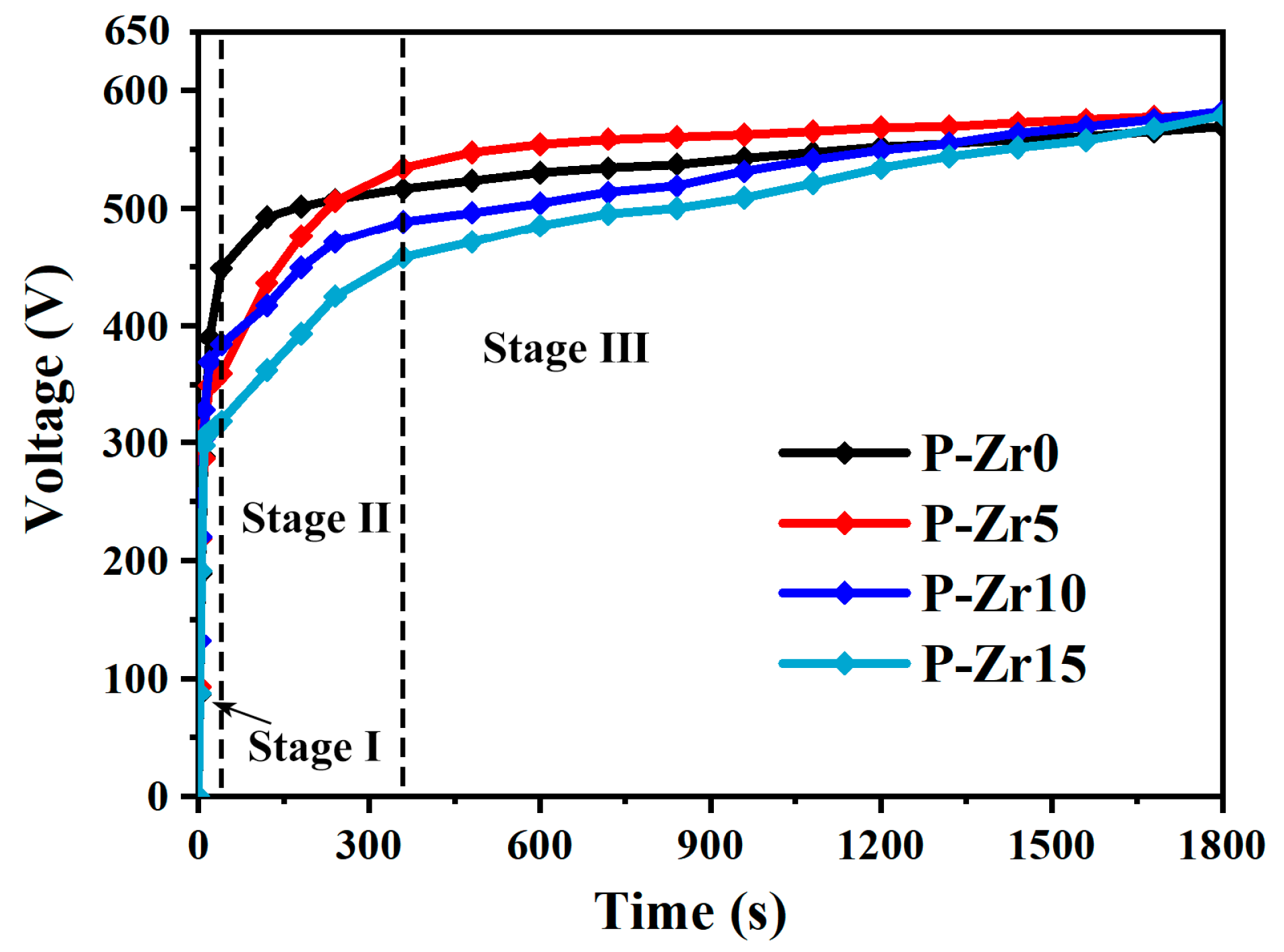
3.1. Voltage–Time Response

Figure 1 shows the voltage–time curves obtained during the PEO process with varying concentrations of K2ZrF6 additive, ranging from 0 to 15 g/L. The graph reveals a distinct trend whereby the breakdown voltage of the PEO system decreased with increasing K2ZrF6 concentration. This decline in breakdown voltage corresponds to the initial phase of the anodic oxidation, characterized by the generation of numerous bubbles and the initiation of the formation of the oxide coating. Subsequently, the process entered a second stage wherein the system became more acidic due to the electrolyte composition. Consequently, the termination voltage at the end of the first stage experienced a decrease. Additionally, the presence of K2ZrF6 induced the hydrolysis of some H+. However, as the reaction progressed, the rate of coating thickening exceeded that of dissolution, resulting in the formation of a PEO coating with appreciable corrosion resistance. Consequently, the subsequent voltage gradually began to rise, albeit at a significantly slower rate than the initial stage, signifying that the second phase was characterized by PEO spark discharge. During the third stage of the PEO process, it was observed that the process voltage increased when 5 g/L K2ZrF6 was added, compared with the absence of K2ZrF6. However, as the concentration of K2ZrF6 increased further, the process voltage exhibited a decreasing trend. This behavior suggests that the addition of a certain amount of K2ZrF6 reduces the electrolyte resistance. However, as the concentration of K2ZrF6 increased, the electrolyte resistance initially decreased and then increased. Notably, when K2ZrF6 was added, the working voltage displayed an initial period of stability, followed by a subsequent increase. This implies that distinct electrochemical reactions take place during these two periods. Nevertheless, after 30 min of treatment, the voltages of the four electrolytes gradually converged, indicating a minimal influence on the final voltage after the addition of K2ZrF6.

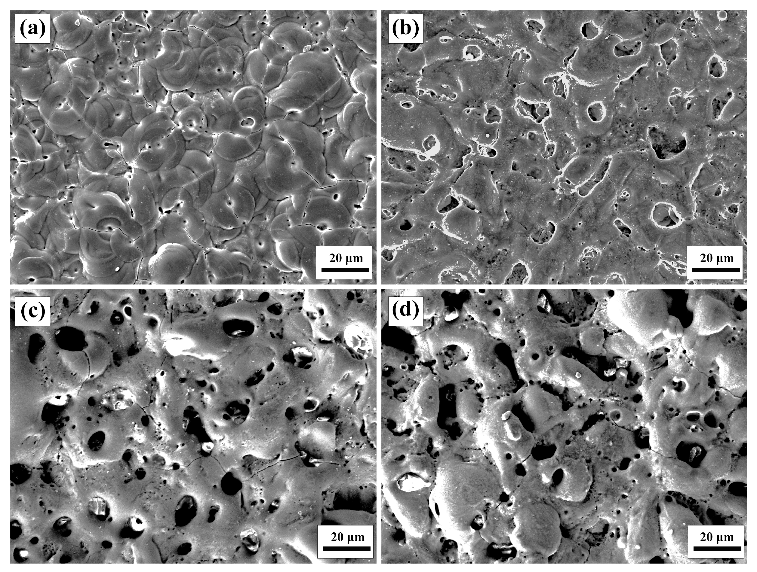
3.2. Effect of K2ZrF6 on Surface Structure and Microstructure

The thickness and roughness of the PEO coatings prepared on the surfaces of the 6061 Al alloy are shown in Figure 2. It can be seen that with the increase in K2ZrF6 concentration, the coating thickness and roughness significantly increased compared with those before the addition of K2ZrF6, which indicates that the K2ZrF6 in the electrolyte was fully involved in the formation of PEO coating and that there was a high coating growth rate in this electrolyte. The marginal difference in roughness between P-Zr10 and P-Zr15 can be attributed to disparities in the spark discharge process. Following the introduction of K2ZrF6, the spark discharge size on the surface of the specimens increased in comparison to that before the addition of K2ZrF6, owing to the influence of the zirconium-containing gel produced as a result of K2ZrF6 addition. Consequently, this led to an increase in roughness. Such changes in coating thickness and roughness were conducive to the enhancement of thermal control properties.
Figure 3 shows the changes in the Al alloy surface coating when the concentration of K2ZrF6 ranged from 0 to 15 g/L. It was found that as the concentration of K2ZrF6 increased, the bump and porosity of the 6061 Al alloy coating increased, resulting in a significant difference in the surface morphology. This change became more pronounced when the K2ZrF6 concentration reached 10 g/L. The presence of pores is closely linked to the discharge pathway of PEO. Consequently, the inclusion of K2ZrF6 augments the spark size, leading to larger discharge pathways and a nonuniform distribution state. As a consequence, the coating surface became rougher. The minimal variation in roughness observed between P-Zr10 and P-Zr15 can be attributed to the substantial thickness, which reduces the impact of pores and protrusions on surface roughness.
To further analyze the surface properties of the PEO coatings, the porosity (percentage of pore area) of the PEO coatings was calculated from micro/macro images. Additionally, the color of the PEO coatings was also quantified using CIE L*a*b*, as shown in Table 1. As the concentration of K2ZrF6 increased, the porosity of the coatings exhibited a corresponding increase. This could be attributed to the formation of numerous large-sized pores and an elevation in coating irregularities. Notably, the porosity escalated from 0.53% in P-Zr0 to 17.76% in P-Zr15. Hence, it can be inferred that the concentration of K2ZrF6 had a substantial influence on the surface structure of the coating, ultimately leading to the observed roughness enhancement. Furthermore, prior to the introduction of K2ZrF6, the coating on the 6061 Al alloy exhibited a darker color, as shown in Figure 4. As alumina is generally white, this discrepancy in color may be attributed to the trace elements within the alloy. As can be seen in Table 1, after the addition of K2ZrF6, L* increased significantly, while a* and b* decreased significantly. This observed alteration can be attributed to the augmented presence of zirconium-containing compounds, resulting in a progressively lighter coating color, while the trace elements in the base material were less influential on the coating color.
Table 2 shows the analysis of the surface elemental content of the coatings prepared after controlling the concentration of K2ZrF6. A comparison of the surface elemental content between the coatings without the addition of K2ZrF6 revealed that the color was significantly influenced by substrate composition. The main elements of the coating after adding K2ZrF6 were O, Al, Zr, F, Na, and K. Among them, Al originated from the substrate, while the other elements were derived from the electrolyte. Notably, the content of F increased with the increase in K2ZrF6 concentration, and the content of Al decreased. Furthermore, it was found that the electrolyte played a major role in the growth of the plasma electrolytic oxide film, while the oxidation of the Al substrate was minimal. This demonstrates that employing a concentrated zirconate electrolyte significantly mitigated the oxidation of the Al substrate itself during the PEO process. Consequently, this mitigation prevented the substrate’s composition from affecting the color of the PEO coating. Consequently, this led to the production of a coating with higher L* and enhanced coating absorption. Moreover, in line with prior studies, the oxide of Zr exhibited a white appearance. Therefore, it can be deduced that the color of PEO coatings is closely associated with the quantity and state of the Zr element present within these coatings.
The XRD patterns of PEO coatings prepared under different conditions are shown in Figure 5. Without the addition of K2ZrF6 in the electrolyte, the composition of the coating phase was mainly Al2O3. However, when K2ZrF6 was added, the diffraction peaks of tetragonal zirconia (t-ZrO2) and monoclinic zirconia (m-ZrO2) appeared in the spectrum, along with weak peaks of Al2O3. This indicates that with the addition of K2ZrF6, the composition of the coating phase was mainly t-ZrO2 and m-ZrO2, with a small amount of Al2O3, and the intensity of the diffraction peaks of t-ZrO2 and m-ZrO2 increased with increasing concentration of K2ZrF6. Clearly, the presence of Zr, O, and F elements in the film layer can be attributed to the electrolyte. This observation further substantiates that the growth process of the PEO coating on the introduced Al alloy is primarily characterized by the deposition of compounds derived from the electrolyte, with the composition of the resultant coating being minimally influenced by the substrate itself. Additionally, as the coating thickness increased, a significant reduction in the intensity of the Al substrate peak became evident, likely attributable to the shielding effect exerted by the coating.
Figure 6 illustrates the cross-sectional elemental distribution within the white PEO coating of the Al alloy. The elemental distribution revealed the presence of Zr, F, and Al within the coatings. This observation further supports the notion that the growth mechanism of the Al alloy PEO coatings involves a combination of substrate oxidation and the deposition of compounds originating from the electrolyte. Additionally, it is evident that the regions of the distribution of Zr and F elements in the coatings exhibited significantly higher brightness than the regions of Al elemental distribution. This observation serves as an additional indication that the growth process of the PEO coatings primarily entails the deposition of compounds from the electrolyte.

3.3. Effect of K2ZrF6 Addition on the Growth Behavior of Coatings

Figure 7 presents a cross-sectional comparison between Al alloys with and without the addition of K2ZrF6. In the images, the yellow dashed line represents the original surface of the base material. The majority of the coatings prepared without the addition of the K2ZrF6 electrolyte are located above the dashed line, as shown in Figure 7a. This indicates that outward growth was dominant in these coatings. However, upon adding K2ZrF6, the coating growth mechanism was a combination of both inward and outward growth, as illustrated in Figure 7b–d. Furthermore, with an increase in K2ZrF6 concentration, the proportion of inward growth in the coating increased. This outcome signifies that K2ZrF6 had a stimulating effect on the inward growth of the coating, with the thickness of inward growth increasing in accordance with the concentration augmentation. Consequently, this contributed to the overall increase in coating thickness. Furthermore, inward growth implies improved bonding of the coating. Consequently, it can be inferred that the growth pattern of Al alloys in phosphate systems is primarily characterized by outward elongation. However, the addition of K2ZrF6 induces a combination of inward and outward growth patterns, thereby enhancing the bonding strength of the coating.
Along with the relevant data, the growth pattern of the coating after the addition of K2ZrF6 is shown in Figure 8. Initially, a minute layer of Al2O3 film formed on the coating surface. Simultaneously, the electrolysis of the K2ZrF6 solution generated suspended Zr(OH)4 particles [38,39,40,41]. Subsequently, the voltage curve with time reached a plateau, signifying that the consumption of the substrate primarily contributed to coating formation. The presence of ZrO3−2, resulting from the decomposition of K2ZrF6, impeded substrate consumption and participated in the reaction, leading to the formation of ZrO2. Consequently, the Al2O3 content in the coating began to diminish, while the ZrO2 content increased, causing an accelerated thickening of the coating. Following a certain period of reaction time, equilibrium was attained between substrate consumption and electrolyte interaction. During this stage, the coating thickening rate stabilized, leading to the flattening of the time–voltage curve. Ultimately, the formed coating in this study predominantly comprised ZrO2, resembling the white PEO coating with thermal control properties, as illustrated in Figure 8b.

3.4. Effect of K2ZrF6 on the Thermal Control Properties of Coatings

Figure 9 shows the total reflection spectra of the PEO coatings prepared under different conditions. It is evident that the coating incorporating K2ZrF6 exhibited significant enhancement across the entire wavelength range (0.2~2.5 μm) in comparison to the PEO coating without K2ZrF6. This enhancement corresponds to a reduction in the absorbance α, with the spectrum demonstrating that P-Zr15 achieved the highest reflectance. The absorbance α values were calculated using Formula (1) and are summarized in Table 3, along with the emissivity ε values. It is notable that as the concentration of K2ZrF6 increased, a consistent decrease in absorbance α and an increase in emissivity ε were observed. These outcomes indicate that the addition of K2ZrF6 effectively reduced the absorbance α and enhanced the emissivity of the coating.
The thermal stability of thermally controlled coatings is also a key factor when used in environments with medium-to-high temperatures, thus limiting their practical application. In this experiment, we investigated the thermal stability of thermally controlled coatings by conducting 80 thermal shock tests at 20–500 °C. Figure 10 shows that the macroscopic morphology of the coating became slightly smoother, and the color of the coating slightly became darker (L* decreased from 90 to 89) after the thermal shock test, which could be explained by the factor of the change in particles on the surface of the coating. After the thermal shock test, the coating surface did not change significantly, and no surface cracks or coating flaking occurred. These experimental findings show that the thermal control coating had good thermal stability [42,43,44].
Based on the results of the above analysis, it is evident that the thermal control properties of PEO coatings are influenced by various factors. In terms of absorbance, the PEO coating applied on 6061Al alloy exhibited high absorbance when prepared using an electrolyte devoid of K2ZrF6 addition [45]. However, upon the introduction of K2ZrF6 into the electrolyte, the absorbance of the PEO coating increased, indicating the influence of the substrate on the absorbance. On the other hand, the addition of color additives can also optimize the absorbance of the coating. In this experiment, the addition of K2ZrF6 to the electrolyte changed the phase composition of the coating from the original Al2O3 to a whiter ZrO2, indicating that not only did it improve the absorbance of the coating, but it also suppressed the influence of the substrate on the absorbance of the coating.
On the other hand, the influence on the emissivity of a coating is multifaceted and encompasses several factors. Firstly, the composition of the coating itself plays a vital role in determining its emissivity, as emissivity is an inherent property of a substance. To achieve a high-emissivity coating, the primary constituents of the coating must possess elevated emissivity properties. In the present experiment, the addition of K2ZrF6 facilitated the transformation of the low-emissivity Al2O3 phase into a relatively high-emissivity ZrO2 phase, thereby enhancing the overall emissivity of the coating. Secondly, when the coating undergoes multiple high-emissivity phases, the emissivity varies across different wavelength ranges due to the diverse magnitudes of emissivity. Consequently, reactions such as stretching and vibration may occur when compounds composed of two or more elements form the coating, thereby augmenting the coating’s emissivity. In this study, the coating phase had limited diversity, resulting in a comparatively lower emissivity. Future investigations should consider introducing other elements to enhance the emissivity of this particular coating. In the current study, the coating phase was too homogeneous, resulting in a relatively low emissivity. The surface structure of the coating also had an effect on the emissivity, with bumps and pores forming on the surface causing a change in roughness and thus affecting the emissivity. This phenomenon arises because coatings with higher roughness possess a larger specific surface area, facilitating improved external energy radiation and, thus, increasing the emissivity. This elucidates why P-Zr15 had a higher emissivity than P-Zr5 for the same phase composition, but the coating roughness used in this study was still too low and should be increased as a means of improving emissivity in subsequent studies. Lastly, it is worth noting that coating thickness exerted a relatively minor influence on emissivity. Extremely thin coatings tended to display lower emissivity, and emissivity values fluctuated as thickness increased until it reached a threshold of approximately 20 μm.

4. Conclusions

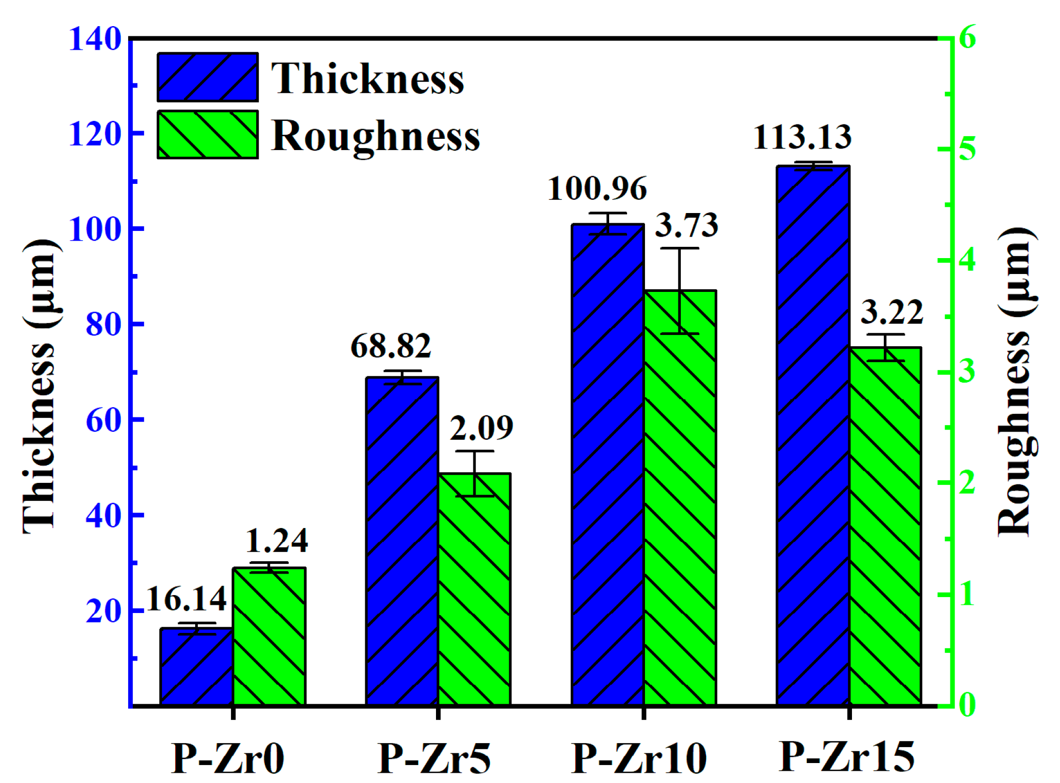
  • The addition of K2ZrF6 fostered an accelerated growth rate of the PEO coatings. The roughness tended to stabilize with increasing K2ZrF6 concentration up to a certain value. The best performance of the PEO coating was achieved at a K2ZrF6 concentration of 15 g/L, when the thickness was 113.13 μm, the roughness was 3.22 μm, and the porosity was 17.75%.
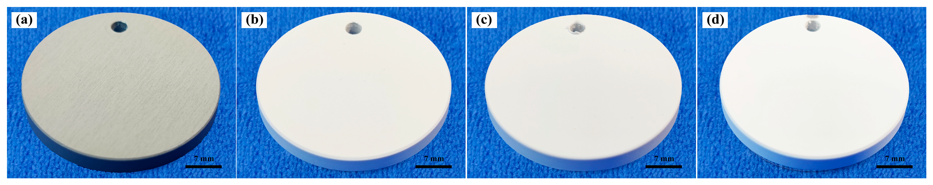
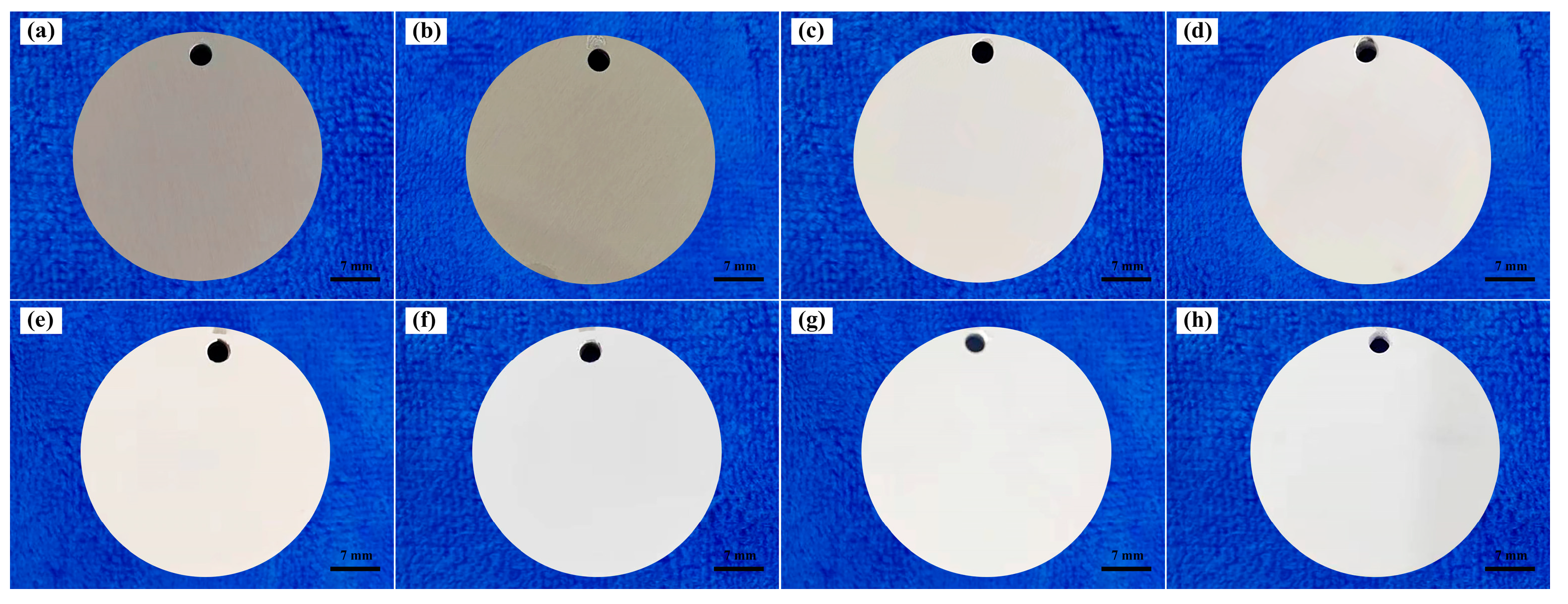
  • In conventional electrolytes, the presence of trace elements within the substrate matrix influences both the color and absorption characteristics of the coating. This influence is contingent upon whether the trace elements within the matrix contain coloring ions. However, the introduction of K2ZrF6 serves to mitigate the impact of trace elements on the coating. Consequently, the L* value of the coating exhibited a notable increase, rising from 71.69 to 90.53.
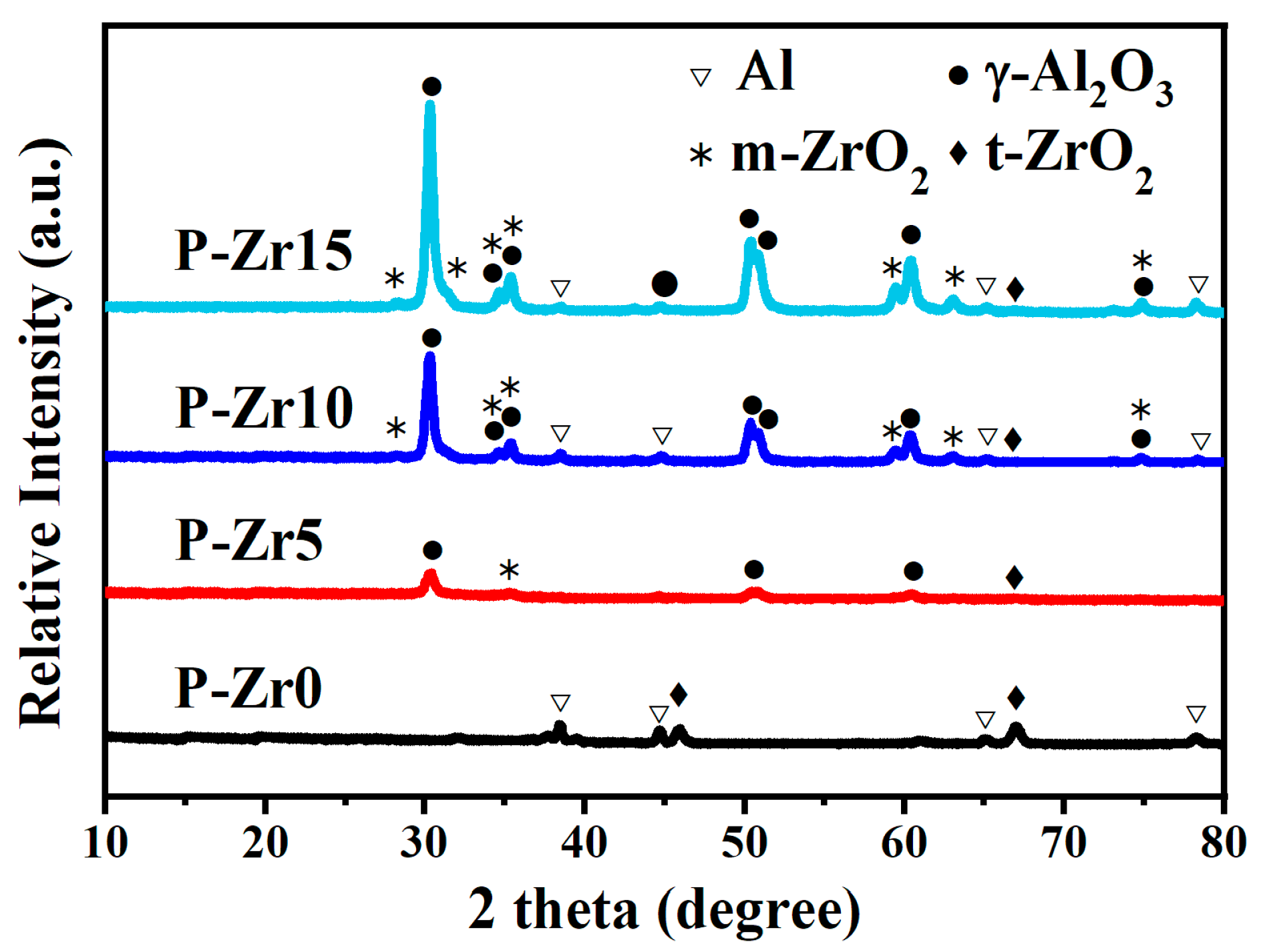
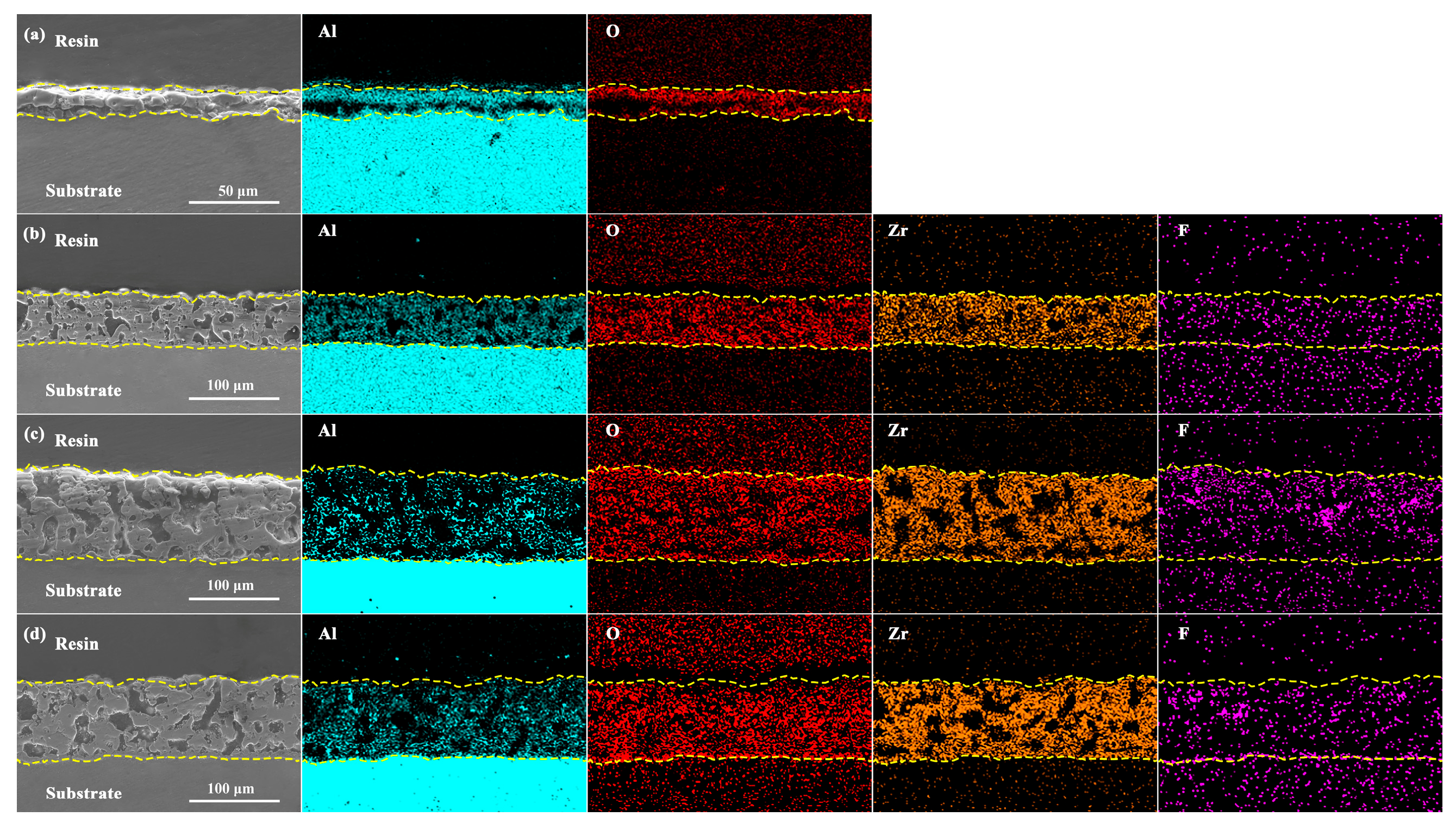
  • The introduction of K2ZrF6 resulted in a considerable reduction in the P element content within the coating, approaching near-zero levels. This reduction facilitated the ingress of Na, F, and K elements into the coating matrix. Consequently, the coating predominantly comprised tetragonal zirconia (t-ZrO2) and monoclinic zirconia (m-ZrO2) phases, with their relative proportions increasing proportionally with the concentration of K2ZrF6. Furthermore, amorphous compounds containing F were also present within the coating structure. This phenomenon arises due to the dominant influence of electrolyte deposition in the formation of this particular coating.
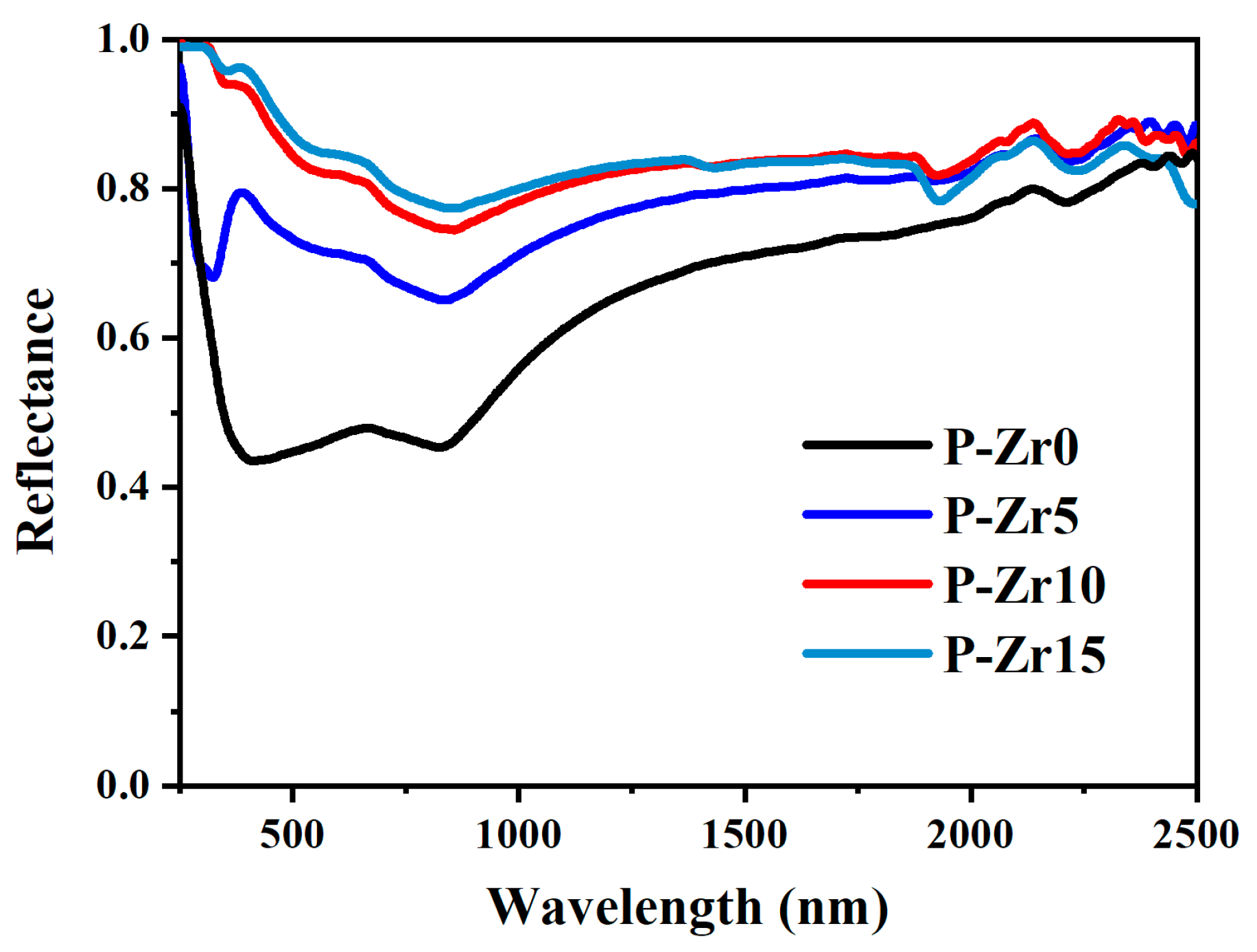
  • The coating exhibited low absorbance (α ≤ 0.20) and high emissivity (ε ≥ 0.68). As the concentration of K2ZrF6 increased, absorbance α decreased, while emissivity ε increased, which may be due to the combined effect of the phase and structure of the coating. The coating of P-Zr15 had the highest absorbance α (0.16) and the highest emissivity ε (0.71). These PEO coatings have potential applications in solar and infrared heating by optimizing the electrolyte.
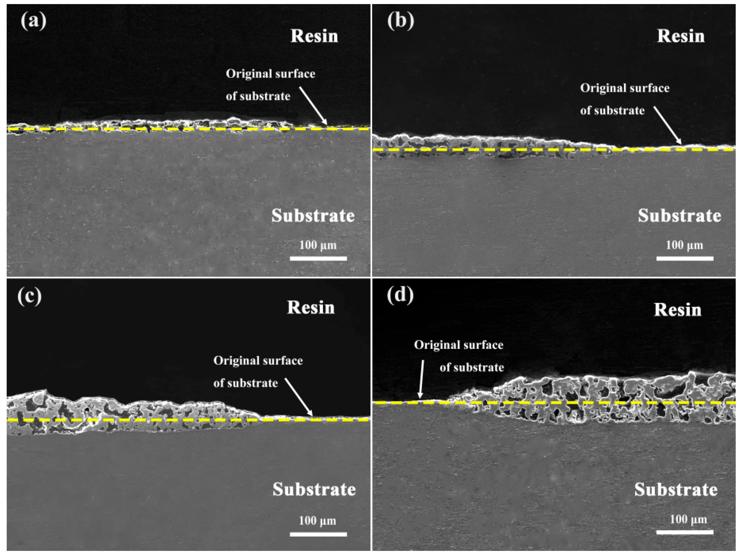
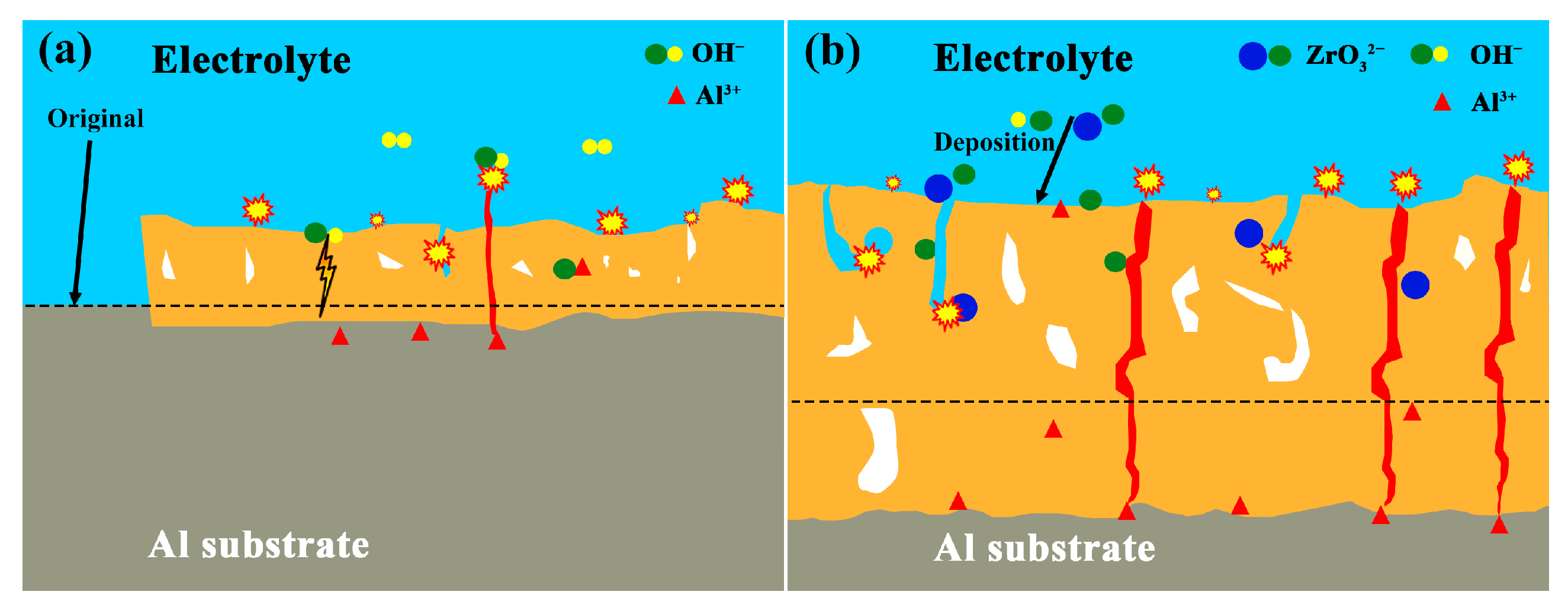
  • The addition of K2ZrF6 changed the growth mechanism of the coating. In the absence of K2ZrF6 in the electrolyte, the PEO coating on the Al alloy surface predominantly exhibited outward growth. However, with the inclusion of K2ZrF6, the growth pattern of the coating transitioned into a combination of outward and inward growth, with the proportion of inward growth progressively increasing alongside the escalating of K2ZrF6 concentration. The incorporation of K2ZrF6 led to favorable conditions that promoted the inward growth of the coating, consequently enhancing the bonding strength between the coating and the substrate. As a result, the addition of K2ZrF6 led to notable thermal shock resistance in the coating, thus demonstrating improved durability under thermal stress conditions.

Author Contributions

The materials were prepared by C.T. and X.C. Data collection and analysis were performed by C.T., X.C. and D.L. The first draft of the manuscript was written by C.T. The manuscript draft was reviewed and edited by C.L. All authors have read and agreed to the published version of the manuscript.

Funding

This research was funded by the National Natural Science Foundation of China (Grant No. 51901099).

Informed Consent Statement

Informed consent was obtained from all subjects involved in the study.

Data Availability Statement

Not applicable.

Acknowledgments

This work was financially supported by the National Natural Science Foundation of China (Grant No. 51901099).

Conflicts of Interest

The authors declare no conflict of interest.

References

  1. Cao, X.Q.; Vassen, R.; Stoever, D. Ceramic materials for thermal barrier coatings. J. Eur. Ceram. Soc. 2004, 24, 1–10. [Google Scholar] [CrossRef]
  2. Hołyńska, M.; Tighe, A.; Semprimoschnig, C. Coatings and Thin Films for Spacecraft Thermo-Optical and Related Functional Applications. Adv. Mater. Interfaces 2018, 5, 1701644. [Google Scholar] [CrossRef]
  3. Wang, Y.H.; Ouyang, J.H.; Li, Z.G.; Wang, Y.M.; Zhou, Y. Enhanced infrared emissivity of MAO coatings formed on Ti2AlNb alloy. Surf. Eng. 2014, 30, 460–466. [Google Scholar] [CrossRef]
  4. Pillai, A.M.; Rajendra, A.; Sharma, A.K.; Bera, P.; Poornima, S.; Sampath, S. Development of vanadium impregnated flat absorber composite PEO coating on AA6061 alloy. Surf. Coat. Technol. 2021, 410, 126891. [Google Scholar] [CrossRef]
  5. Zhang, H.P.; Wang, C.; Wang, Y.M.; Wang, S.Q.; Chen, G.L.; Zou, Y.C.; Deng, C.M.; Jia, D.C.; Zhou, Y. Ca-Mn co-doping LaCrO3 coating with high emissivity and good mechanical property for enhancing high-temperature radiant heat dissipation. J. Eur. Ceram. Soc. 2022, 42, 7288–7299. [Google Scholar] [CrossRef]
  6. Zhang, H.P.; Wang, C.; Wang, Y.M.; Wang, S.Q.; Zou, Y.C.; Chen, G.L.; Deng, C.M.; Jia, D.C.; Zhou, Y. Evaluation on the microstructure and thermal infrared emissivity of Ca2+-doped ytterbium chromate coating deposited by saucer-shaped porous feedstocks for high-temperature thermal protection. Appl. Surf. Sci. 2023, 608, 155210. [Google Scholar] [CrossRef]
  7. Nastic, A.; Jodoin, B. Evaluation of Heat Transfer Transport Coefficient for Cold Spray Through Computational Fluid Dynamics and Particle In-Flight Temperature Measurement Using a High-Speed IR Camera. J. Therm. Spray Technol. 2018, 27, 1491–1517. [Google Scholar] [CrossRef]
  8. Lu, F.F.; Ma, K.; Li, C.X.; Yasir, M.; Luo, X.T.; Li, C.j. Enhanced corrosion resistance of cold-sprayed and shot-peened aluminum coatings on LA43M magnesium alloy. Surf. Coat. Technol. 2020, 394, 125865. [Google Scholar] [CrossRef]
  9. Jiao, M.Y.; Wu, J.Y.; Guo, L.L.; Han, P.D.; Du, H.Y.; Hu, X.X. Fiber reinforced scalelike MoSi2-borosilicate glass coating with improved contact damage resistance and thermal shock resistance. Ceram. Int. 2021, 47, 11037–11042. [Google Scholar] [CrossRef]
  10. Zhang, H.P.; Wang, Y.M.; Hu, Y.L.; Mao, W.; Zou, Y.C.; Chen, G.L.; Wang, S.Q.; Jia, D.C.; Zhou, Y. Preparation, microstructure, and thermophysical properties of Cr3+-modified cordierite high emissivity ceramic for metal thermal protection. J. Alloys Compd. 2022, 892, 162164. [Google Scholar] [CrossRef]
  11. Lee, J.; Kim, D.; Choi, C.H.; Chung, W. Nanoporous anodic alumina oxide layer and its sealing for the enhancement of radiative heat dissipation of aluminum alloy. Nano Energy 2017, 31, 504–513. [Google Scholar] [CrossRef]
  12. Zhang, Z.H.; Sridhar, S.; Wei, G.Y.; Yu, Y.D.; Zhang, Z.Q.; Jiang, L.; Yang, Y.M.; Shahzad, M.W.; Chen, X.; Xu, B.B. A highly controlled fabrication of porous anodic aluminium oxide surface with versatile features by spatial thermo-anodization. Surf. Coat. Technol. 2021, 408, 126809. [Google Scholar] [CrossRef]
  13. Amiri, H.; Mohammadi, I.; Afshar, A. Electrophoretic deposition of nano-zirconia coating on AZ91D magnesium alloy for bio-corrosion control purposes. Surf. Coat. Technol. 2017, 311, 182–190. [Google Scholar] [CrossRef]
  14. Zhang, J.; Xie, Z.H.; Chen, H.; Hu, C.; Li, L.X.; Hu, B.N.; Song, Z.W.; Yan, D.L.; Yu, G. Electroless deposition and characterization of a double-layered Ni-B/Ni-P coating on AZ91D Mg alloy from eco-friendly fluoride-free baths. Surf. Coat. Technol. 2018, 342, 178–189. [Google Scholar] [CrossRef]
  15. Jiang, S.X.; Xu, J.T.; Miao, D.G.; Peng, L.H.; Shang, S.M.; Zhu, P. Water-repellency, ultraviolet protection and infrared emissivity properties of AZO film on polyester fabric. Ceram. Int. 2017, 43, 2424–2430. [Google Scholar] [CrossRef]
  16. Zahoor, A.; Xu, C.; Shahid, T.; Anwar, M.A.; Song, Z.L. Effects of O2 flux on structure, optical properties and hydrophobicity of highly emissive antireflective HfO2 thin films by magnetron sputtering. Vacuum 2022, 197, 110824. [Google Scholar] [CrossRef]
  17. Wang, Y.M.; Lei, T.Q.; Guo, L.X.; Jiang, B.L. Fretting wear behaviour of microarc oxidation coatings formed on titanium alloy against steel in unlubrication and oil lubrication. Appl. Surf. Sci. 2006, 252, 8113–8120. [Google Scholar] [CrossRef]
  18. Liu, C.C.; Xu, T.; Shao, Q.Y.; Huang, S.; Jiang, B.L.; Liang, J.; Li, H.T. Effects of beta phase on the growth behavior of plasma electrolytic oxidation coating formed on magnesium alloys. J. Alloys Compd. 2019, 784, 414–421. [Google Scholar] [CrossRef]
  19. Kaseem, M.; Fatimah, S.; Nashrah, N.; Ko, Y.G. Recent progress in surface modification of metals coated by plasma electrolytic oxidation: Principle, structure, and performance. Prog. Mater. Sci. 2021, 117, 100735. [Google Scholar] [CrossRef]
  20. Sobolev, A.; Bograchev, D.; Zinigrad, M.; Borodianskiy, K. Evolution of corrosion on microstructure of ceramic coating produced by plasma electrolytic oxidation in molten salt. Ceram. Int. 2022, 48, 10990–10998. [Google Scholar] [CrossRef]
  21. Sela, S.; Borodianskiy, K. Synthesis of ceramic surface on Zr alloy using plasma electrolytic oxidation in molten salt. Surf. Interfaces 2023, 36, 102533. [Google Scholar] [CrossRef]
  22. Sobolev, A.; Peretz, T.; Borodianskiy, K. Synthesis and growth mechanism of ceramic coatings on an Al-Cu alloy using plasma electrolytic oxidation in molten salt. J. Alloys Compd. 2021, 869, 159309. [Google Scholar] [CrossRef]
  23. Shrestha, S.; Dunn, B.D. Advanced plasma electrolytic oxidation treatment for protection of light weight materials and structures in a space environment. Surf. World 2007, 14, 40–44. [Google Scholar]
  24. Arunnellaiappan, T.; Krishna, L.R.; Anoop, S.; Rani, R.U.; Rameshbabu, N. Fabrication of multifunctional black PEO coatings on AA7075 for spacecraft applications. Surf. Coat. Technol. 2016, 307, 735–746. [Google Scholar]
  25. Wu, X.H.; Qin, W.; Cui, B.; Jiang, Z.H.; Lu, W.Q. Black Ceramic Thermal Control Coating Prepared by Microarc Oxidation. Int. J. Appl. Ceram. Technol. 2008, 4, 269–275. [Google Scholar] [CrossRef]
  26. Wang, Y.M.; Tian, H.; Shen, X.E.; Wen, L.; Ouyang, J.H.; Zhou, Y.; Jia, D.C.; Guo, L.X. An elevated temperature infrared emissivity ceramic coating formed on 2024 aluminium alloy by microarc oxidation. Ceram. Int. 2013, 39, 2869–2875. [Google Scholar] [CrossRef]
  27. Kim, Y.S.; Yang, H.W.; Shin, K.R.; Ko, Y.G.; Shin, D.H. Heat dissipation properties of oxide layers formed on 7075 Al alloy via plasma electrolytic oxidation. Surf. Coat. Technol. 2015, 269, 114–118. [Google Scholar] [CrossRef]
  28. Kim, D.; Sung, D.; Lee, J.; Kim, Y.; Chung, W. Composite plasma electrolytic oxidation to improve the thermal radiation performance and corrosion resistance on an Al substrate. Appl. Surf. Sci. 2015, 357, 1396–1402. [Google Scholar] [CrossRef]
  29. Yao, Z.P.; Su, P.B.; Shen, Q.X.; Ju, P.F.; Wu, C.; Zhai, Y.F.; Jiang, Z.H. Preparation of thermal control coatings on Ti alloy by plasma electrolytic oxidation in K2ZrF6 solution. Surf. Coat. Technol. 2015, 269, 273–278. [Google Scholar] [CrossRef]
  30. Yao, Z.P.; Xia, Q.X.; Shen, Q.X.; Ju, P.F.; Su, P.B.; Hu, B.; Jiang, Z.H. A facile preparation of ceramic coatings on Ti alloys for thermal protection systems. Sol. Energy Mater. Sol. Cells 2015, 143, 236–241. [Google Scholar] [CrossRef]
  31. Xia, Q.X.; Wang, J.K.; Liu, G.J.; Wei, H.; Li, D.Q.; Yao, Z.P.; Jiang, Z.H. Effects of electric parameters on structure and thermal control property of PEO ceramic coatings on Ti alloys. Surf. Coat. Technol. 2016, 307, 1284–1290. [Google Scholar] [CrossRef]
  32. Al Bosta, M.M.S.; Ma, K.J.; Chien, H.H. The effect of MAO processing time on surface properties and low temperature infrared emissivity of ceramic coating on aluminium 6061 alloy. Infrared Phys. Technol. 2013, 60, 323–334. [Google Scholar] [CrossRef]
  33. Al Bosta, M.M.S.; Ma, K.J. Influence of electrolyte temperature on properties and infrared emissivity of MAO ceramic coating on 6061 aluminum alloy. Infrared Phys. Technol. 2014, 67, 63–72. [Google Scholar] [CrossRef]
  34. Ge, Y.L.; Wang, Y.M.; Zhang, Y.F.; Guo, L.X.; Jia, D.C.; Ouyang, J.H.; Zhou, Y. The improved thermal radiation property of SiC doped microarc oxidation ceramic coating formed on niobium metal for metal thermal protective system. Surf. Coat. Technol. 2017, 309, 880–886. [Google Scholar] [CrossRef]
  35. Zou, Y.C.; Wang, Y.M.; Zhang, H.J.; Wei, D.Q.; Jin, T.; Wang, H.W.; Liao, S.Z.; Jia, D.C.; Zhou, Y. Al2O3/reduced graphene oxide double-layer radiative coating for efficient heat dissipation. Mater. Design. 2018, 157, 130–140. [Google Scholar] [CrossRef]
  36. Fan, D.S.; Sun, H.; Li, Q. Thermal control properties of radiative cooling foil based on transparent fluorinated polyimide. Sol. Energy Mater. Sol. Cells 2019, 195, 250–257. [Google Scholar] [CrossRef]
  37. Wang, Z.W.; Wang, Y.M.; Liu, Y.; Xu, J.L.; Guo, L.X.; Zhou, Y.; Ouyang, J.H.; Dai, J.M. Microstructure and infrared emissivity property of coating containing TiO2 formed on titanium alloy by microarc oxidation. Curr. Appl. Phys. 2011, 11, 1405–1409. [Google Scholar] [CrossRef]
  38. Wu, Z.D.; Yao, Z.P.; Jiang, Z.H. Preparation and structure of microarc oxidation ceramic coatings containing ZrO2 grown on LY12 Al alloy. Rare Met. 2008, 27, 55–58. [Google Scholar] [CrossRef]
  39. Barati, N.; Meletis, E.I.; Fard, F.G.; Yerokhin, A.; Rastegari, S.; Faghihi-Sani, M.A. Al2O3-ZrO2 nanostructured coatings using DC plasma electrolytic oxidation to improve tribological properties of Al substrates. Appl. Surf. Sci. 2015, 356, 927–934. [Google Scholar] [CrossRef]
  40. Rehman, Z.U.; Shin, S.H.; Kaseem, M.; Uzair, M.; Koo, B.H. Towards a compact coating formed on A16061 alloy in phosphate based electrolyte via two-step PEO process and K2ZrF6 additives. Surf. Coat. Technol. 2017, 328, 355–360. [Google Scholar] [CrossRef]
  41. Pintilei, G.L.; Crismaru, V.I.; Abrudeanu, M.; Munteanu, C.; Luca, D.; Istrate, B. The Influence of Zro2/20%Y2O3 and Al2O3 Deposited Coatings to the Behavior of an Aluminum Alloy Subjected to Mechanical Shock. Appl. Surf. Sci. 2015, 352, 169–177. [Google Scholar] [CrossRef]
  42. Ma, D.L.; Lu, C.H.; Fang, Z.G.; Yan, W.G.; Wei, L.; Ni, Y.R.; Xu, Z.Z. Preparation of high absorbance and high emittance coatings on 6061 aluminum alloy with a pre-deposition method by plasma electrolytic oxidation. Appl. Surf. Sci. 2016, 389, 874–881. [Google Scholar] [CrossRef]
  43. Li, Q.B.; Yang, W.B.; Liu, C.C.; Wang, D.A.; Liang, J. Correlations between the growth mechanism and properties of micro-arc oxidation coatings on titanium alloy: Effects of electrolytes. Surf. Coat. Technol. 2017, 316, 162–170. [Google Scholar] [CrossRef]
  44. Xia, Q.X.; Li, X.; Yao, Z.P.; Jiang, Z.H. Investigations on the thermal control properties and corrosion resistance of MAO coatings prepared on Mg-5Y-7Gd-1Nd-0.5Zr alloy. Surf. Coat. Technol. 2021, 409, 126874. [Google Scholar] [CrossRef]
  45. Bayati, M.R.; Zargar, H.R.; Talimian, A.; Ziaee, A.; Molaei, R. Characterization of Al2O3–TiO2 nano porous solar absorbers derived via MAO/sol-gel hybrid process. Surf. Coat. Technol. 2011, 205, 2483–2489. [Google Scholar] [CrossRef]
Figure 1. Time–voltage response curves for the PEO processes conducted in electrolytes with different concentrations of K2ZrF6.
Materials 16 04142 g001
Figure 2. Thickness and roughness of PEO coatings with different concentrations of K2ZrF6.
Materials 16 04142 g002
Figure 3. Surface SEM images of the PEO coatings obtained with different K2ZrF6 contents: (a) P-Zr0; (b) P-Zr5; (c) P-Zr10; (d) P-Zr15.
Materials 16 04142 g003
Figure 4. Comparative photographs of the surface color of PEO-coated samples: (a) P-Zr0; (b) P-Zr5; (c) P-Zr10; (d) P-Zr15.
Materials 16 04142 g004
Figure 5. XRD patterns of the four PEO coatings formed in electrolytes containing varying quantities of K2ZrF6.
Materials 16 04142 g005
Figure 6. Cross-sectional morphology and cross-sectional elemental distribution: (a) P-Zr0; (b) P-Zr5; (c) P-Zr10; (d) P-Zr15.
Materials 16 04142 g006
Figure 7. The growth characteristics of the coatings with and without the addition of K2ZrF6: (a) P-Zr0; (b) P-Zr5; (c) P-Zr10; (d) P-Zr15.
Materials 16 04142 g007
Figure 8. Schematic diagrams for the growth behaviors of the PEO coatings prepared in electrolytes without (a) and with (b) K2ZrF6.
Materials 16 04142 g008
Figure 9. Solar reflection spectra of PEO coatings under different conditions.
Materials 16 04142 g009
Figure 10. Comparison of the surface condition of the P-Zr15 coating before and after the thermal shock test; before the test: (a) P-Zr0; (c) P-Zr5; (e) P-Zr10; (g) P-Zr15. After 80 cycles: (b) P-Zr0; (d) P-Zr5; (f) P-Zr10; (h) P-Zr15.
Materials 16 04142 g010
Table 1. Porosity and CIE L*a*b* results of PEO coatings under different conditions.
SpecimensPorosity (%)L*a*b*
P-Zr00.5371.691.445.57
P-Zr57.0784.40.361.85
P-Zr1011.9589.330.611.06
P-Zr1517.7590.530.980.48
Table 2. Elemental distribution of PEO-coated surface of 6061 Al alloy.
SpecimensContent of Elements (wt.%)
OAlPSiNaZrKF
P-Zr040.7856.441.131.200.45000
P-Zr521.6419.6600.313.5839.874.5110.43
P-Zr1019.9710.310.880.995.6938.097.8416.23
P-Zr1520.6210.350.011.045.1942.117.5213.16
Table 3. Solar absorbance and infrared emissivity of PEO coatings.
Specimensαε
P-Zr00.480.49
P-Zr50.270.68
P-Zr100.180.69
P-Zr150.160.71
Disclaimer/Publisher’s Note: The statements, opinions and data contained in all publications are solely those of the individual author(s) and contributor(s) and not of MDPI and/or the editor(s). MDPI and/or the editor(s) disclaim responsibility for any injury to people or property resulting from any ideas, methods, instructions or products referred to in the content.

