
Low Frequency Attenuation Characteristics of Two-Dimensional Hollow Scatterer Locally Resonant Phonon Crystals

Abstract
1. Introduction
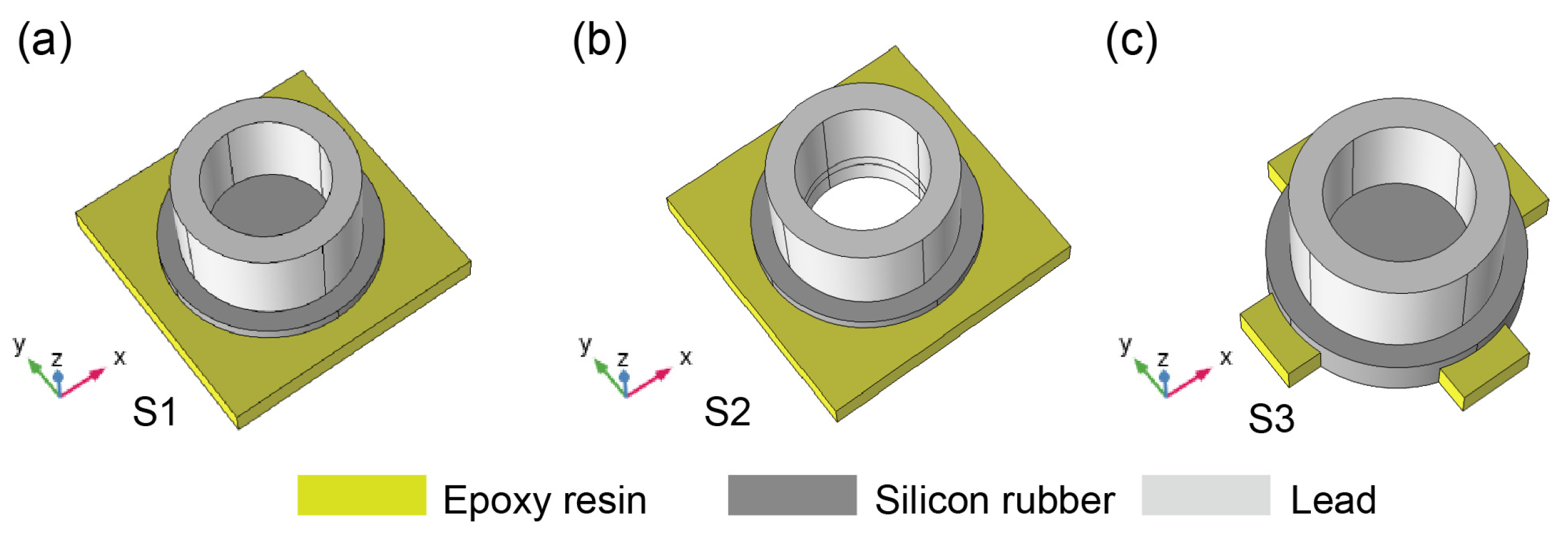
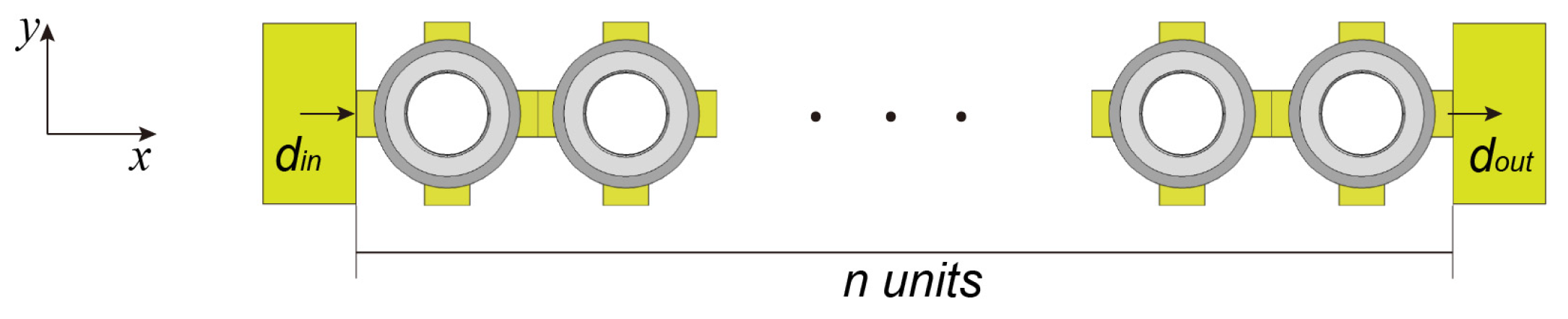
2. Model and Method
3. Simulation and Analysis
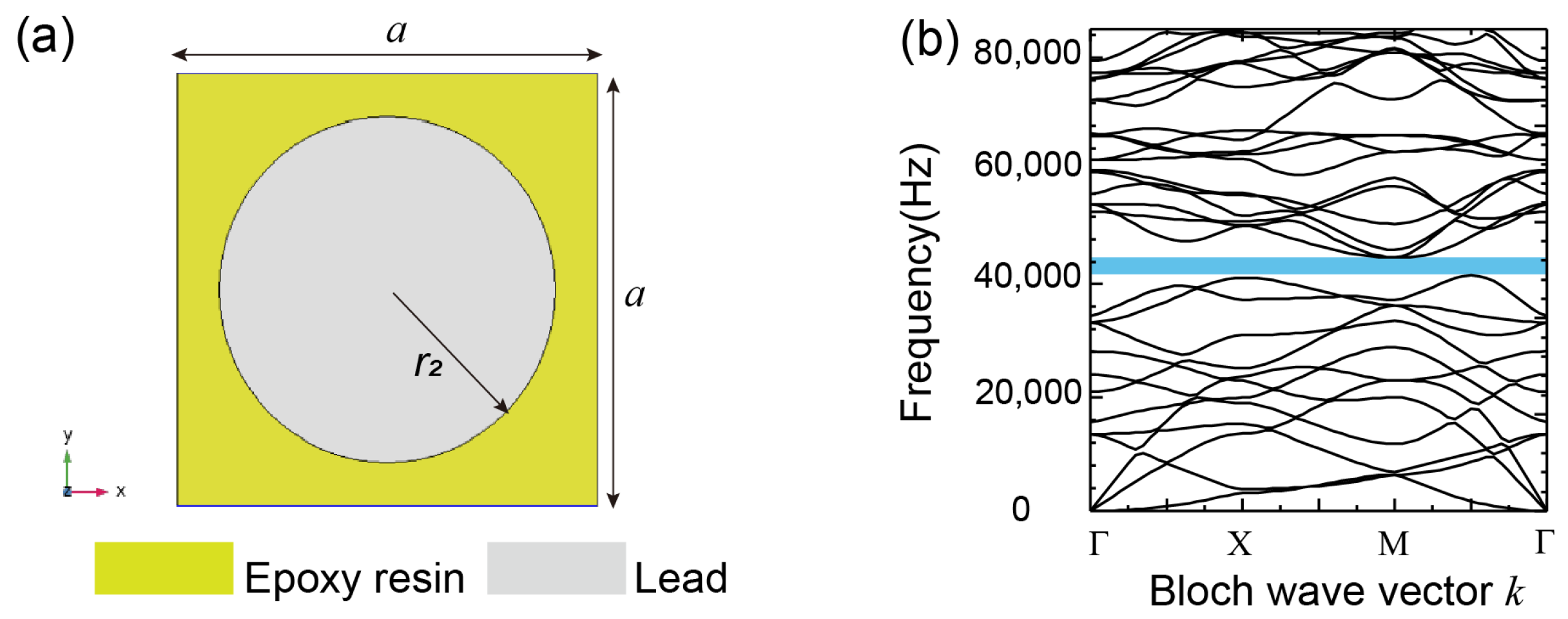
3.1. Two-Component Phononic Crystal Plate
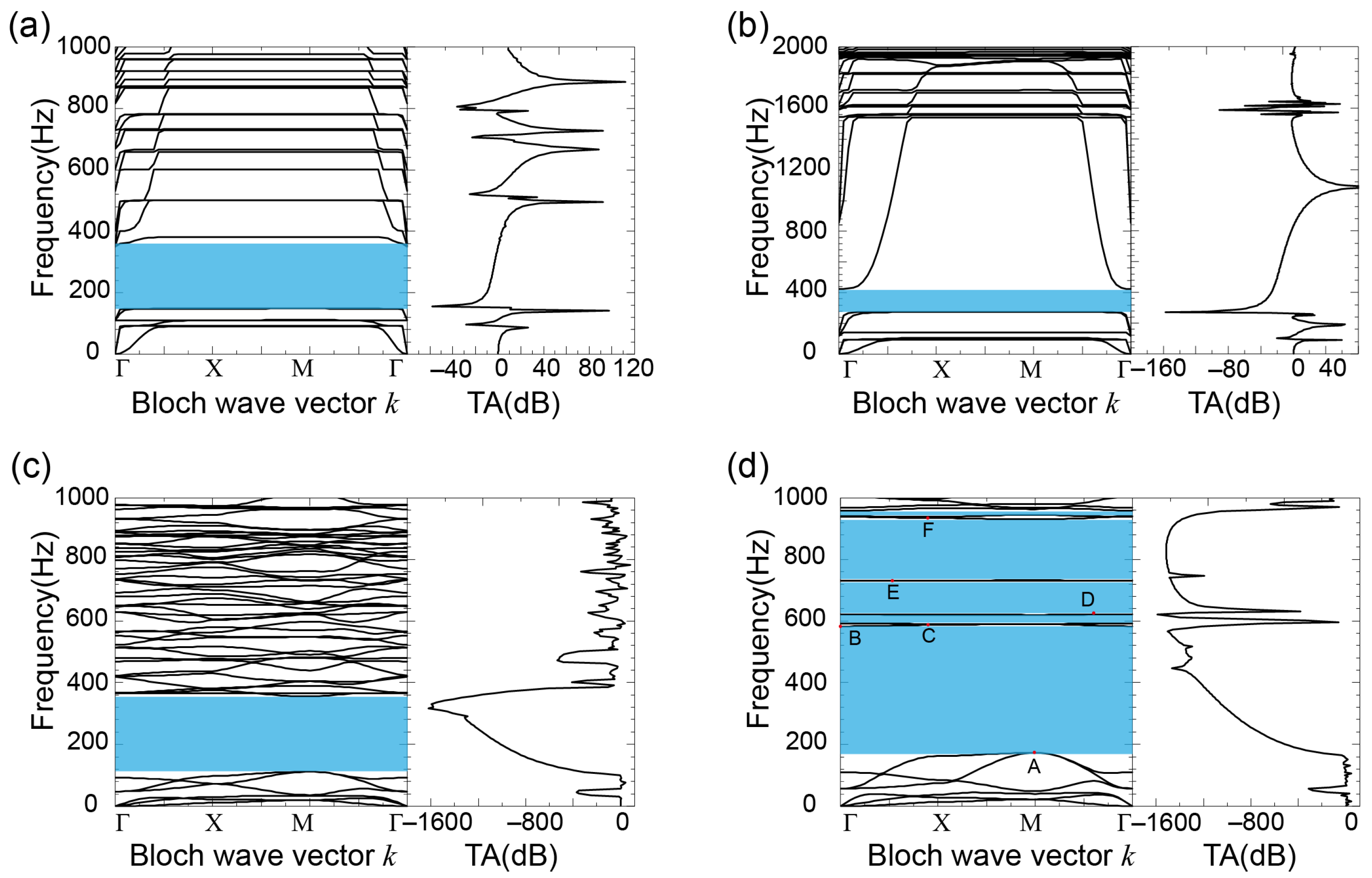
3.2. Calculation of Band Gap Characteristics
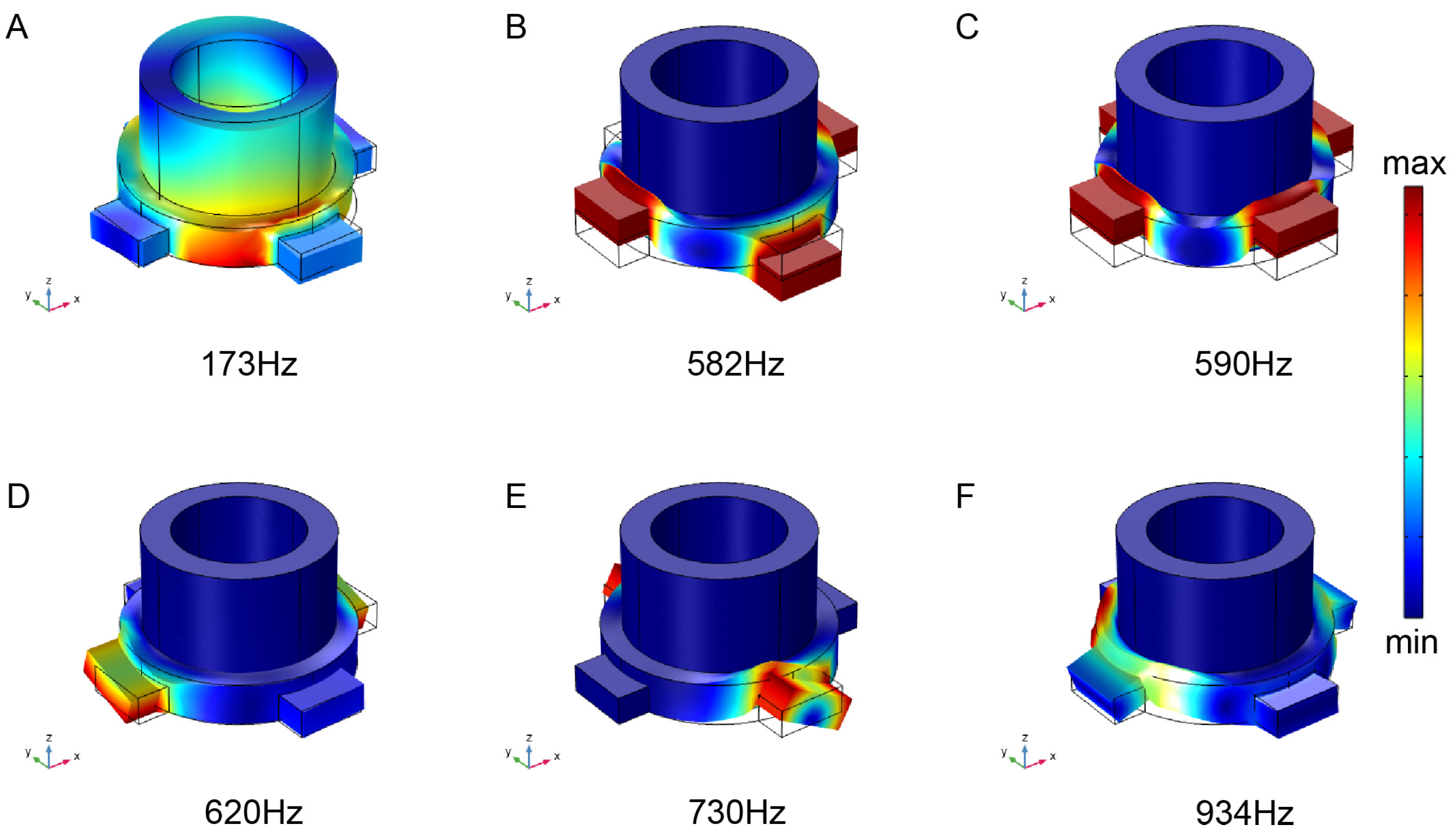
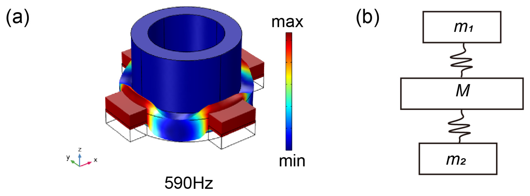
3.3. Analysis of Band Gap Formation Mechanism
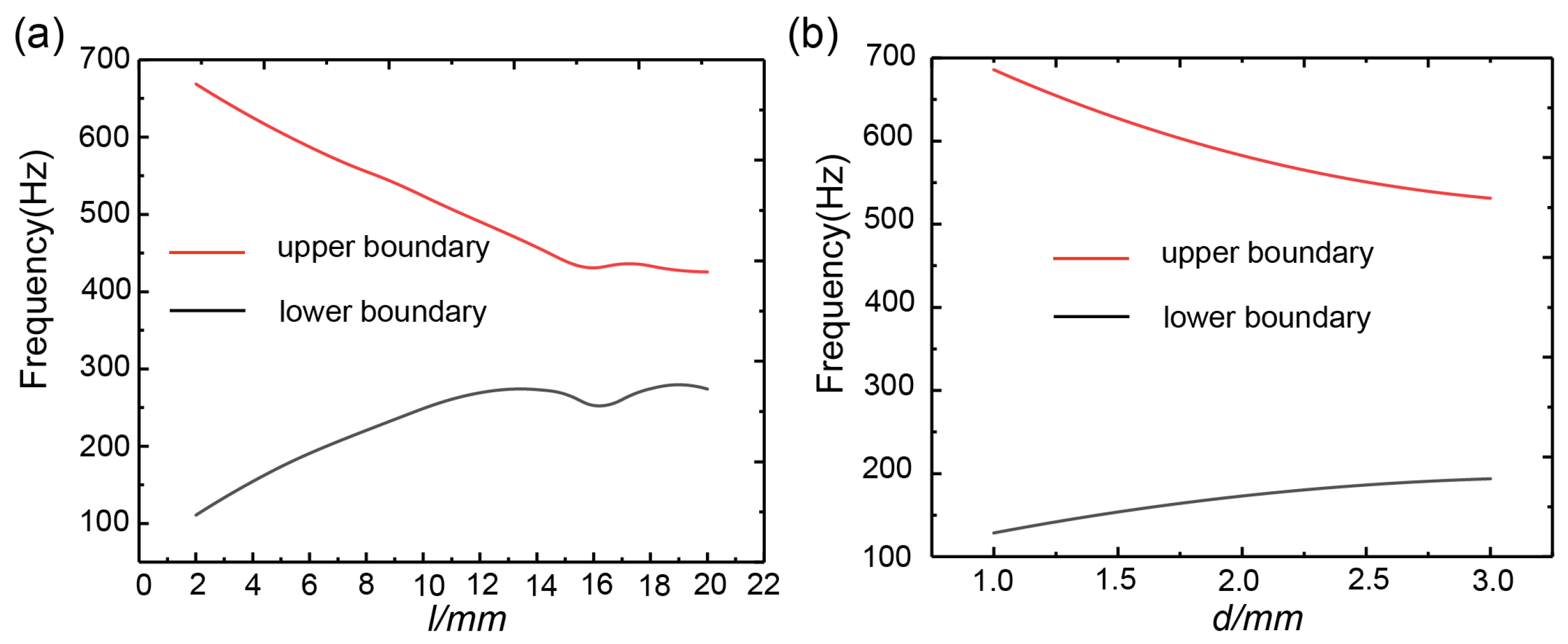
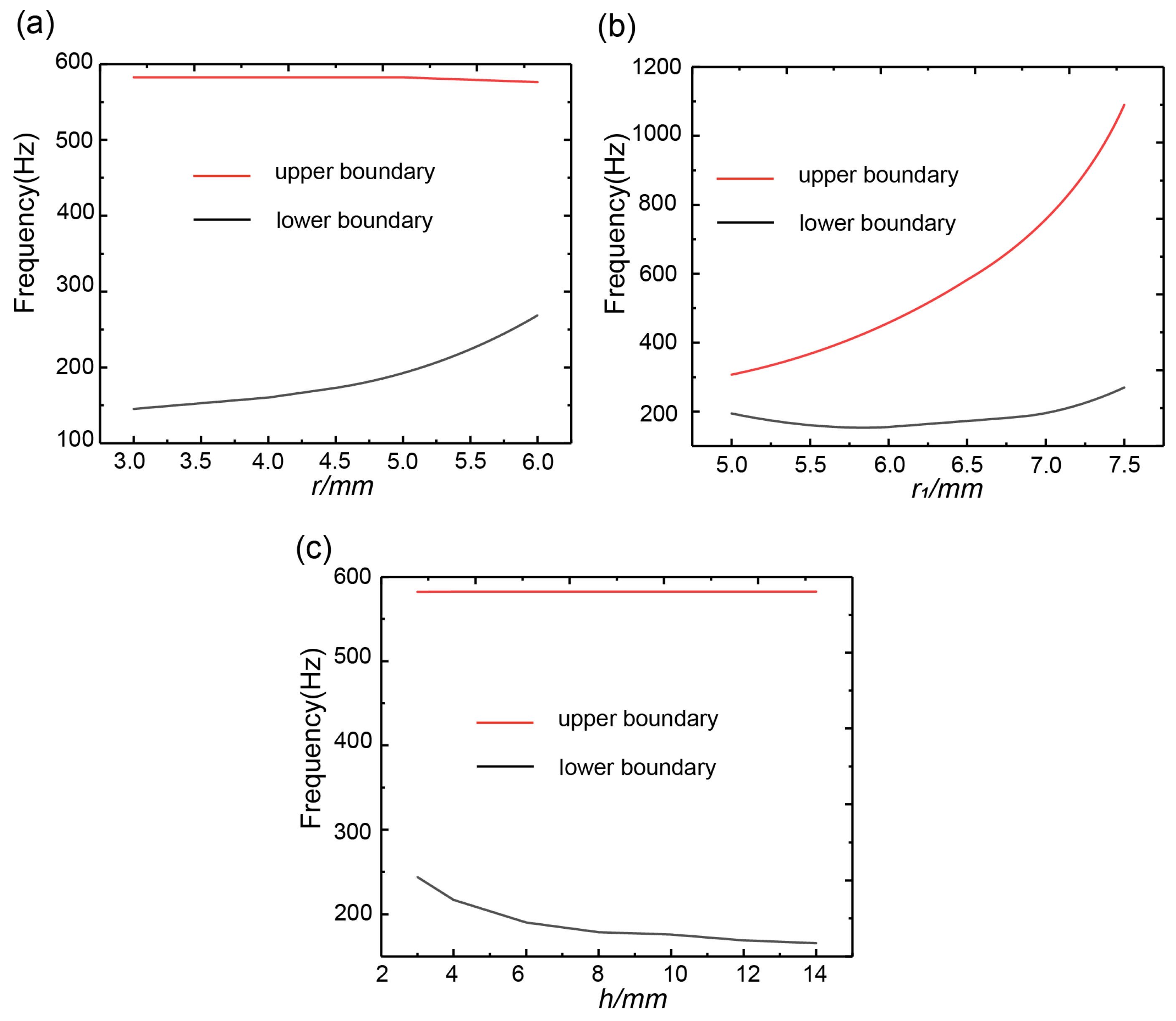
3.4. Effect of Geometric Parameters on the Band Gap of Phonon Crystals
4. Conclusions
Author Contributions
Funding
Institutional Review Board Statement
Informed Consent Statement
Data Availability Statement
Conflicts of Interest
References
- Brillouin, L. Propagation in Periodic Structures: Electric Filters and Crystal Lattices; Dover Publications: Mineola, NY, USA, 1953. [Google Scholar]
- Maldovan, M. Sound and heat revolutions in phononics. Nature 2013, 503, 209–217. [Google Scholar] [CrossRef] [PubMed]
- Wang, Y.F.; Wang, Y.Z.; Wu, B.; Chen, W.; Wang, Y.S. Tunable and active phononic crystals and metamaterials. Appl. Mech. Rev. 2020, 72, 040801. [Google Scholar] [CrossRef]
- Li, H.; Zhao, G.; Zhu, M.; Guo, J.; Wang, C. Robust Large-Sized Photochromic Photonic Crystal Film for Smart Decoration and Anti-Counterfeiting. ACS Appl. Mater. Interfaces 2022, 14, 14618–14629. [Google Scholar] [CrossRef] [PubMed]
- Yadav, A.; Gerislioglu, B.; Ahmadivand, A.; Kaushik, A.; Cheng, G.J.; Ouyang, Z.; Wang, Q.; Yadav, V.S.; Mishra, Y.M.; Wu, Y.; et al. Controlled self-assembly of plasmon-based photonic nanocrystals for high performance photonic technologies. Nano Today 2021, 37, 101072. [Google Scholar] [CrossRef]
- Kushwaha, M.S.; Halevi, P.; Dobrzynski, L.; Djafari-Rouhani, B. Acoustic band structure of periodic elastic composites. Phys. Rev. Lett. 1993, 71, 2022. [Google Scholar] [CrossRef]
- Khelif, A.; Achaoui, Y.; Benchabane, S.; Laude, V.; Aoubiza, B. Locally resonant surface acoustic wave band gaps in a two-dimensional phononic crystal of pillars on a surface. Phys. Rev. B 2010, 81, 214303. [Google Scholar] [CrossRef]
- Zhou, X.Z.; Wang, Y.S.; Zhang, C. Effects of material parameters on elastic band gaps of two-dimensional solid phononic crystals. J. Appl. Phys. 2009, 106, 014903. [Google Scholar] [CrossRef]
- Reinke, C.M.; Su, M.F.; Olsson, R.H., III; El-Kady, I. Realization of optimal bandgaps in solid-solid, solid-air, and hybrid solid-air-solid phononic crystal slabs. Appl. Phys. Lett. 2011, 98, 061912. [Google Scholar] [CrossRef]
- Liu, Z.; Zhang, X.; Mao, Y.; Zhu, Y.Y.; Yang, Z.; Chan, C.T.; Sheng, P. Locally resonant sonic materials. Science 2000, 289, 1734–1736. [Google Scholar] [CrossRef]
- Pennec, Y.; Djafari-Rouhani, B.; Larabi, H.; Vasseur, J.O.; Hladky-Hennion, A.C. Low-frequency gaps in a phononic crystal constituted of cylindrical dots deposited on a thin homogeneous plate. Phys. Rev. B 2008, 78, 104105. [Google Scholar] [CrossRef]
- Hsu, J.C. Local resonances-induced low-frequency band gaps in two-dimensional phononic crystal slabs with periodic stepped resonators. J. Phys. D Appl. Phys. 2011, 44, 055401. [Google Scholar] [CrossRef]
- Oudich, M.; Li, Y.; Assouar, B.M.; Hou, Z. A sonic band gap based on the locally resonant phononic plates with stubs. New J. Phys. 2010, 12, 083049. [Google Scholar] [CrossRef]
- Yang, Z.; Mei, J.; Yang, M.; Chan, N.H.; Sheng, P. Membrane-type acoustic metamaterial with negative dynamic mass. Phys. Rev. Lett. 2008, 101, 204301. [Google Scholar] [CrossRef] [PubMed]
- Ding, H.X.; Shen, Z.H.; Ni, X.W.; Zhu, X.F. Multi-splitting and self-similarity of band gap structures in quasi-periodic plates of Cantor series. Appl. Phys. Lett. 2012, 100, 083501. [Google Scholar] [CrossRef]
- Huang, H.; Huo, S.; Chen, J. Subwavelength elastic topological negative refraction in ternary locally resonant phononic crystals. Int. J. Mech. Sci. 2021, 198, 106391. [Google Scholar] [CrossRef]
- Badreddine Assouar, M.; Oudich, M. Enlargement of a locally resonant sonic band gap by using double-sides stubbed phononic plates. Appl. Phys. Lett. 2012, 100, 123506. [Google Scholar] [CrossRef]
- Deng, J.; Guasch, O.; Zheng, L. Reconstructed Gaussian basis to characterize flexural wave collimation in plates with periodic arrays of annular acoustic black holes. Int. J. Mech. Sci. 2021, 194, 106179. [Google Scholar] [CrossRef]
- Li, Y.; Chen, T.; Wang, X.; Xi, Y.; Liang, Q. Enlargement of locally resonant sonic band gap by using composite plate-type acoustic metamaterial. Phys. Lett. A 2015, 379, 412–416. [Google Scholar] [CrossRef]
- Pennec, Y.; Vasseur, J.O.; Djafari-Rouhani, B.; Dobrzyński, L.; Deymier, P.A. Two-dimensional phononic crystals: Examples and applications. Surf. Sci. Rep. 2010, 65, 229–291. [Google Scholar] [CrossRef]
- Zhao, D.G.; Li, Y.; Zhu, X.F. Broadband lamb wave trapping in cellular metamaterial plates with multiple local resonances. Sci. Rep. 2015, 5, 9376. [Google Scholar] [CrossRef]
- Zhu, H.F.; Sun, X.W.; Song, T.; Wen, X.D.; Liu, X.X.; Feng, J.S.; Liu, Z.J. Tunable characteristics of low-frequency bandgaps in two-dimensional multivibrator phononic crystal plates under prestrain. Sci. Rep. 2021, 11, 8389. [Google Scholar] [CrossRef] [PubMed]
- Wang, X.P.; Jiang, P.; Song, A.L. Low-frequency and tuning characteristic of band gap in a symmetrical double-sided locally resonant phononic crystal plate with slit structure. Int. J. Mod. Phys. B 2016, 30, 1650203. [Google Scholar] [CrossRef]
- Yu, K.; Chen, T.; Wang, X. Band gaps in the low-frequency range based on the two-dimensional phononic crystal plates composed of rubber matrix with periodic steel stubs. Phys. B Condens. Matter 2013, 416, 12–16. [Google Scholar] [CrossRef]
- Zhang, Z.; Han, X.K. A new hybrid phononic crystal in low frequencies. Phys. Lett. A 2016, 380, 3766–3772. [Google Scholar] [CrossRef]
- Li, S.; Chen, T.; Wang, X.; Li, Y.; Chen, W. Expansion of lower-frequency locally resonant band gaps using a double-sided stubbed composite phononic crystals plate with composite stubs. Phys. Lett. A 2016, 380, 2167–2172. [Google Scholar] [CrossRef]
- Li, L.; Gang, X.; Sun, Z.; Zhang, X.; Zhang, F. Design of phononic crystals plate and application in vehicle sound insulation. Adv. Eng. Softw. 2018, 125, 19–26. [Google Scholar] [CrossRef]
- Li, L.; Wen, T.; Han, J.; Yang, P. Two component phononic crystal integrated bandgap algorithm and regularity of bandgap parameter. J. Sci. Technol. Eng. 2015, 15, 123–127. [Google Scholar]
- Zhu, X.; Xu, T.; Liu, S.; Cheng, J. Study of acoustic wave behavior in silicon-based one-dimensional phononic-crystal plates using harmony response analysis. J. Appl. Phys. 2009, 106, 104901. [Google Scholar]
- Zhu, X.; Zou, X.-Y.; Liang, B.; Cheng, J. One-way mode transmission in one-dimensional phononic crystal plates. J. Appl. Phys. 2010, 108, 124909. [Google Scholar]


| Material | Density ρ (kg/m3) | Young Modulus E (×1010 Pa) | Poisson Ratio v |
|---|---|---|---|
| Lead | 11,600 | 4.08 | 0.42 |
| Silicon rubber | 1300 | 1.37 | 0.47 |
| Epoxy resin | 1180 | 0.435 | 0.38 |
| Band | xmax | W | K | f1 | f2 |
|---|---|---|---|---|---|
| 7th | 4.32 | 8164.96 | 875.02 | 579.44 | 582 |
| 9th | 7.32 | 8697.08 | 324.62 | 590.62 | 620 |
Disclaimer/Publisher’s Note: The statements, opinions and data contained in all publications are solely those of the individual author(s) and contributor(s) and not of MDPI and/or the editor(s). MDPI and/or the editor(s) disclaim responsibility for any injury to people or property resulting from any ideas, methods, instructions or products referred to in the content. |
© 2023 by the authors. Licensee MDPI, Basel, Switzerland. This article is an open access article distributed under the terms and conditions of the Creative Commons Attribution (CC BY) license (https://creativecommons.org/licenses/by/4.0/).
Share and Cite
Xu, J.; Chen, C. Low Frequency Attenuation Characteristics of Two-Dimensional Hollow Scatterer Locally Resonant Phonon Crystals. Materials 2023, 16, 3982. https://doi.org/10.3390/ma16113982
Xu J, Chen C. Low Frequency Attenuation Characteristics of Two-Dimensional Hollow Scatterer Locally Resonant Phonon Crystals. Materials. 2023; 16(11):3982. https://doi.org/10.3390/ma16113982
Chicago/Turabian StyleXu, Jingcheng, and Changzheng Chen. 2023. "Low Frequency Attenuation Characteristics of Two-Dimensional Hollow Scatterer Locally Resonant Phonon Crystals" Materials 16, no. 11: 3982. https://doi.org/10.3390/ma16113982
APA StyleXu, J., & Chen, C. (2023). Low Frequency Attenuation Characteristics of Two-Dimensional Hollow Scatterer Locally Resonant Phonon Crystals. Materials, 16(11), 3982. https://doi.org/10.3390/ma16113982