
Experimental and Numerical Investigation of Flow Structure and Heat Transfer Behavior of Multiple Jet Impingement Using MgO-Water Nanofluids

Abstract
1. Introduction
2. Nanofluids Synthesis and Thermo-Physical Properties
3. Experimental Setup
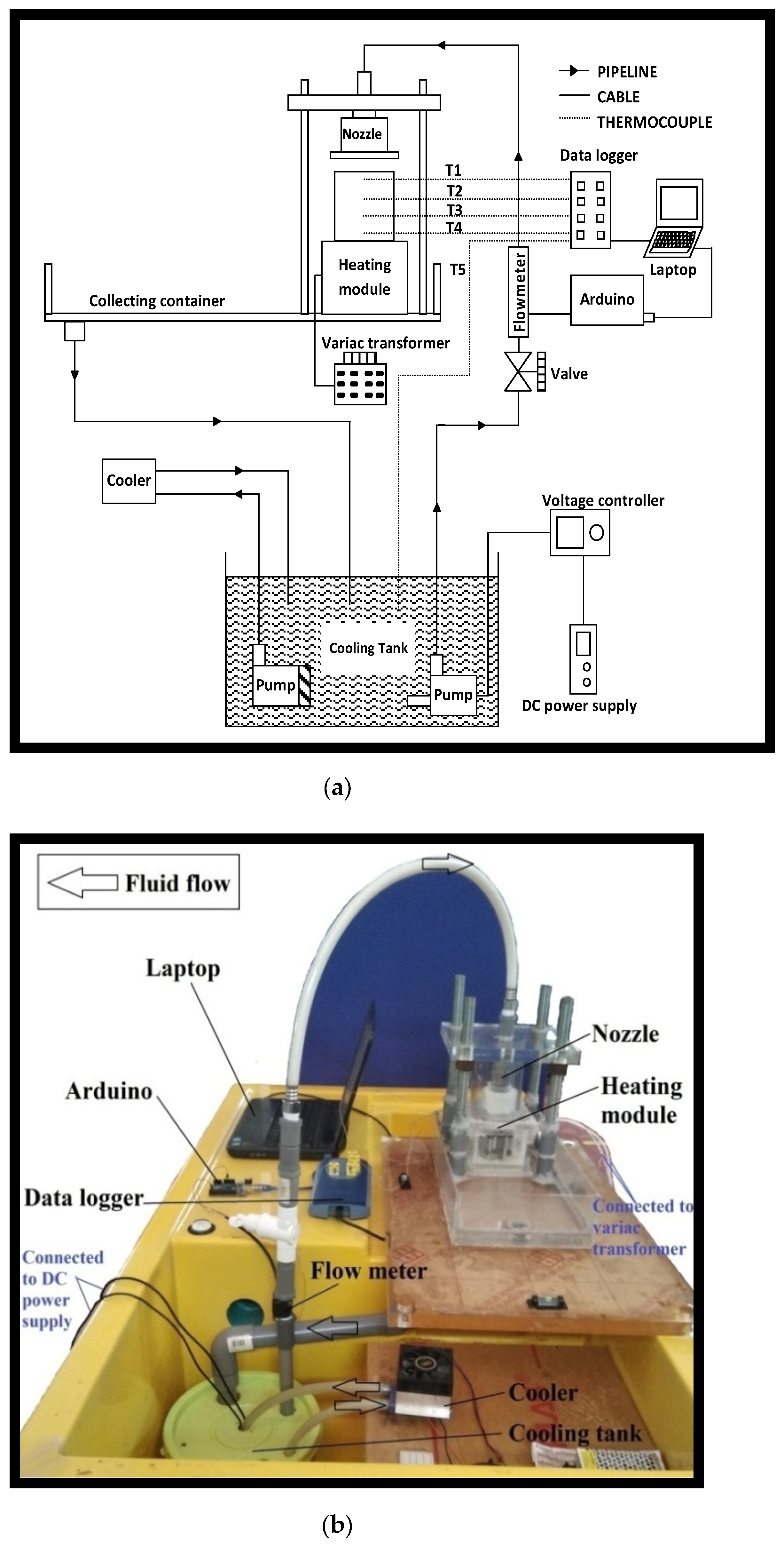
3.1. Test Rig
3.2. Data Reduction
3.3. Uncertainty Analysis
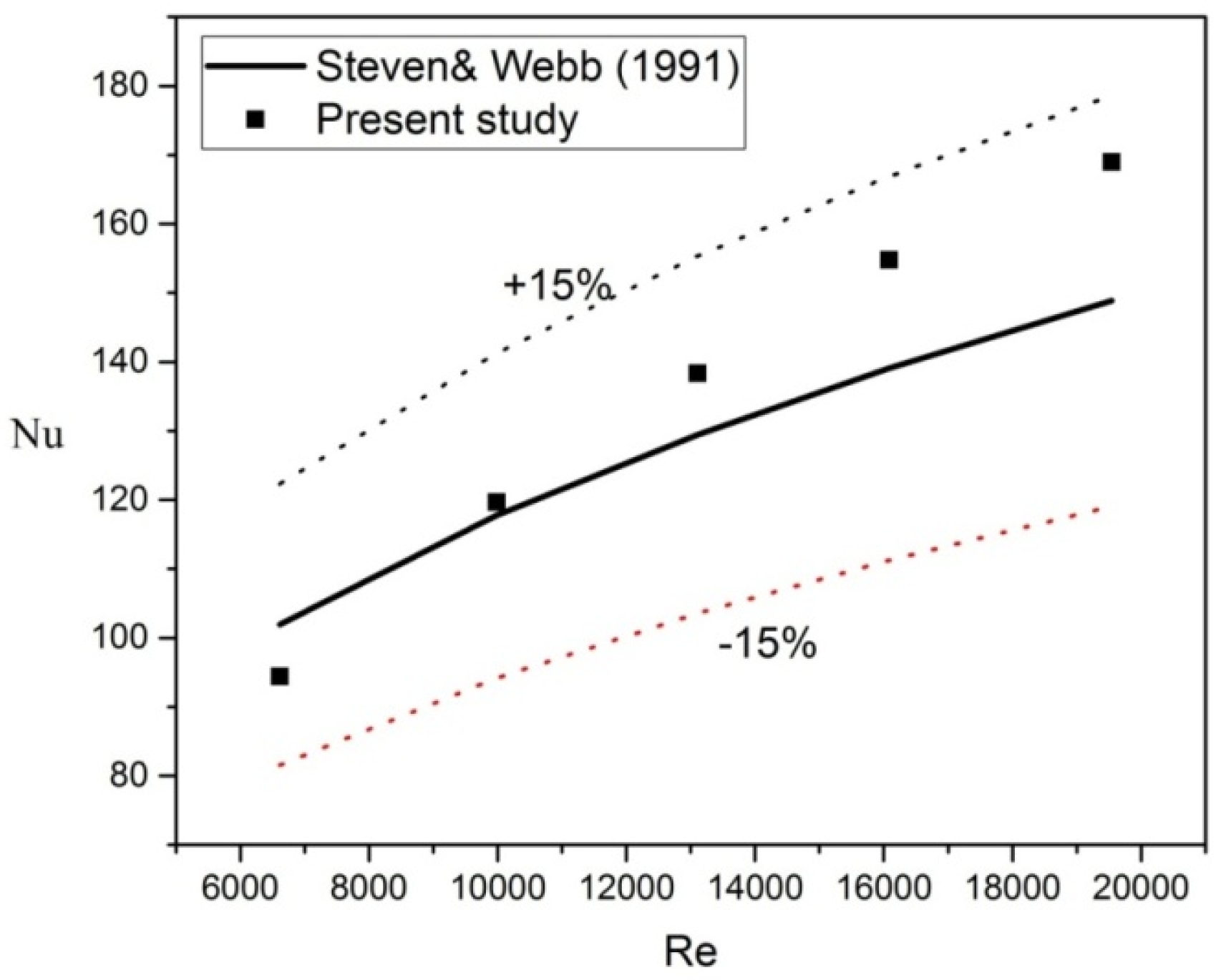
3.4. Validation of Measurement
4. Numerical Analysis
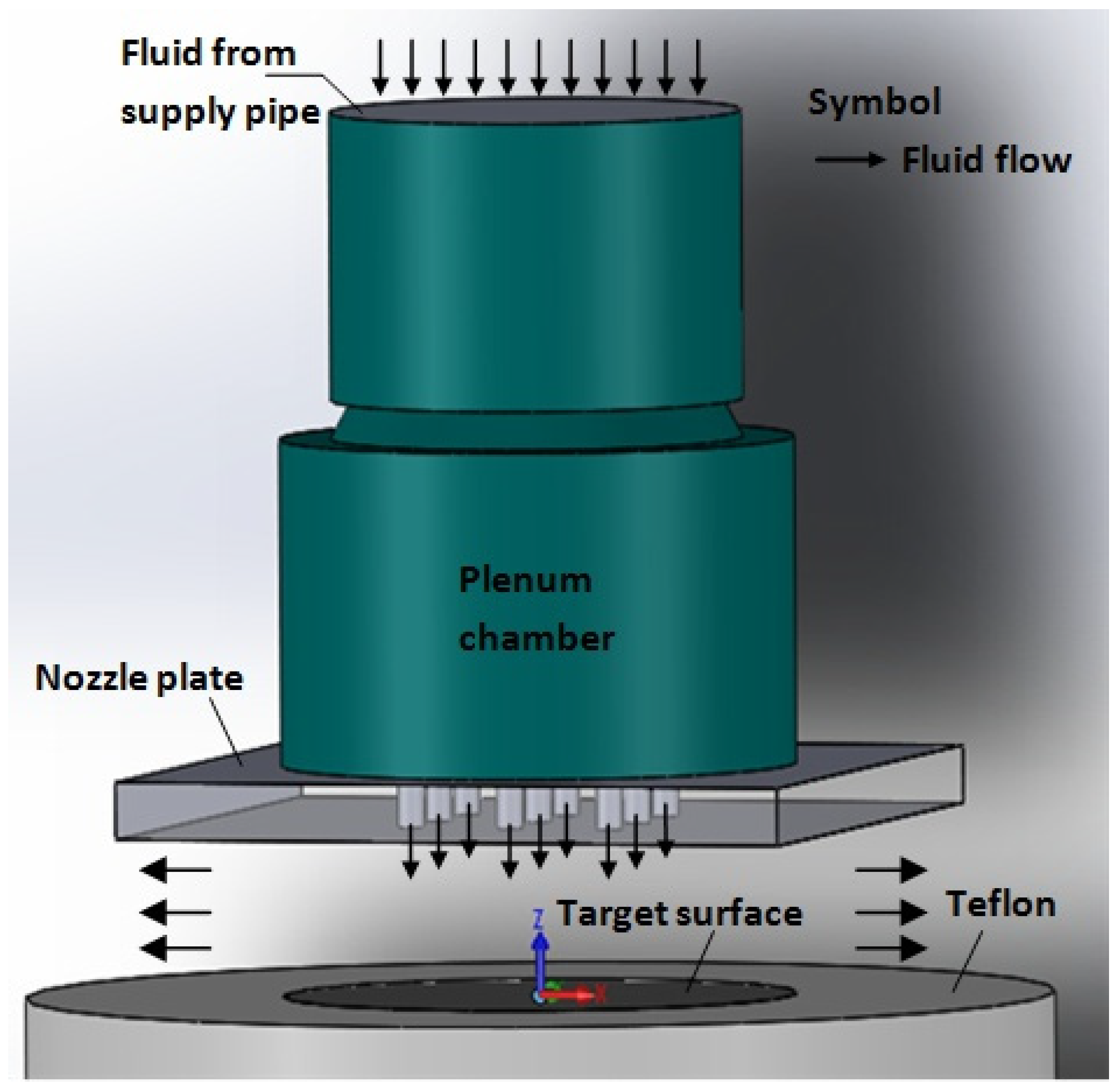
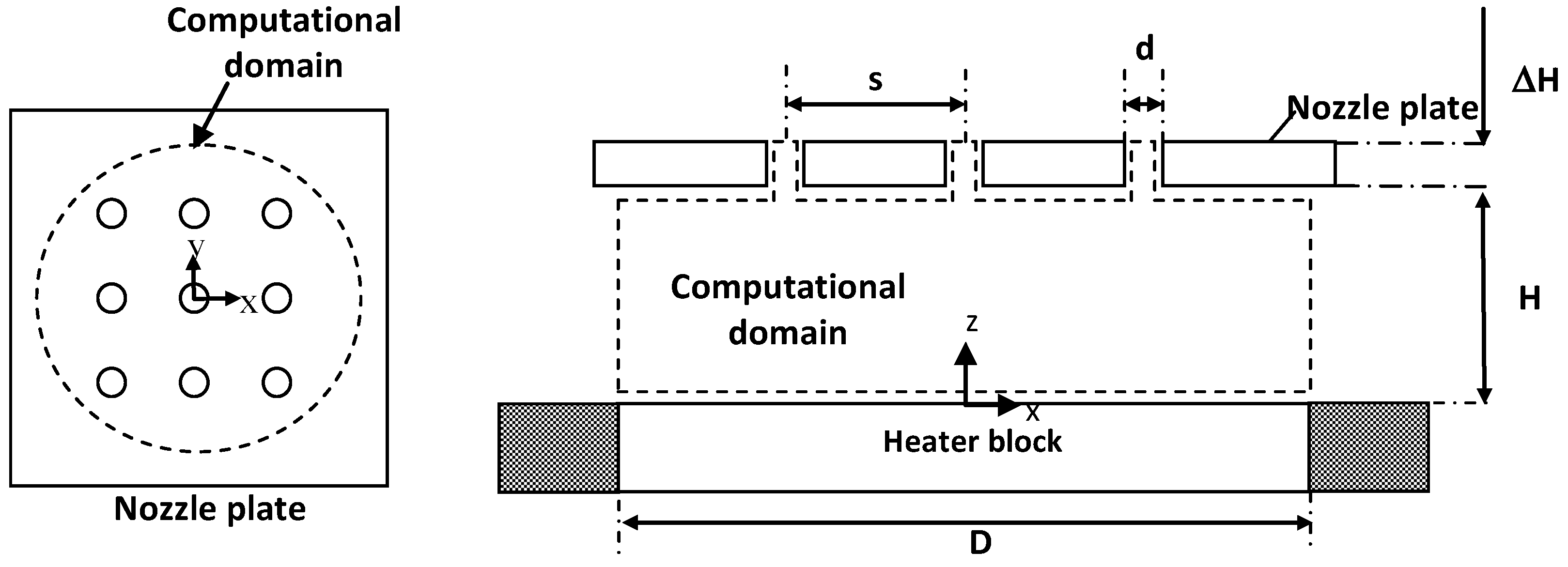
4.1. Problem Description
4.2. Mathematical Formulation
4.2.1. Governing Equations
4.2.2. Turbulent Model
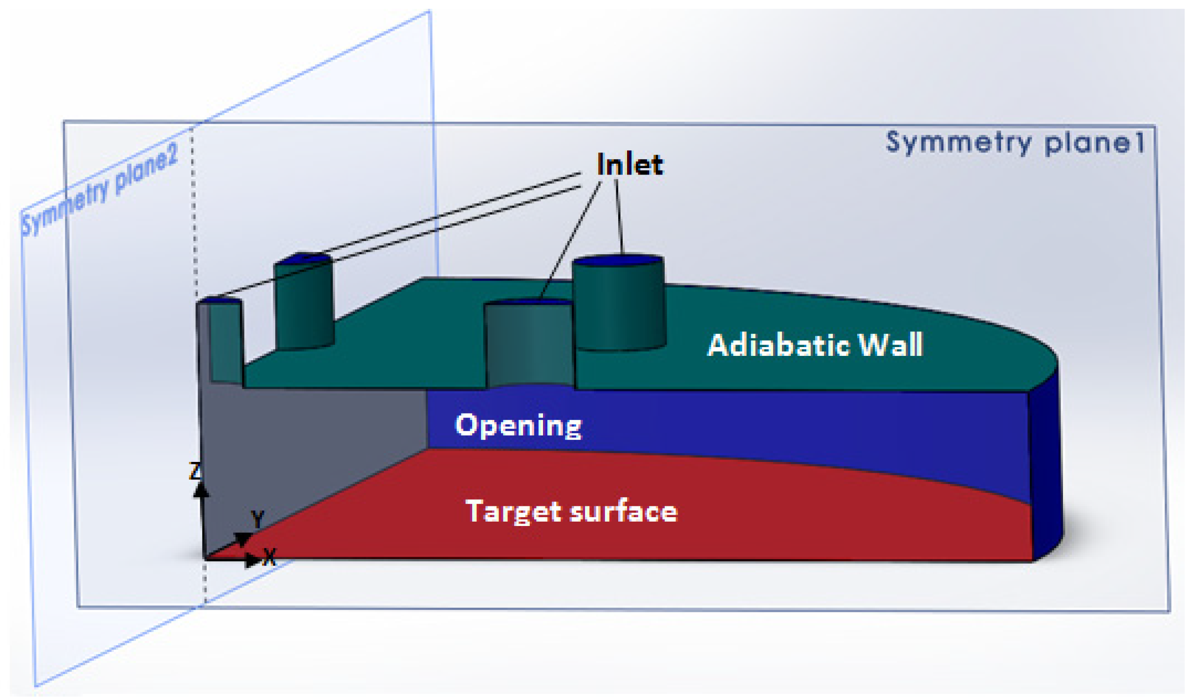
4.3. Boundary Conditions
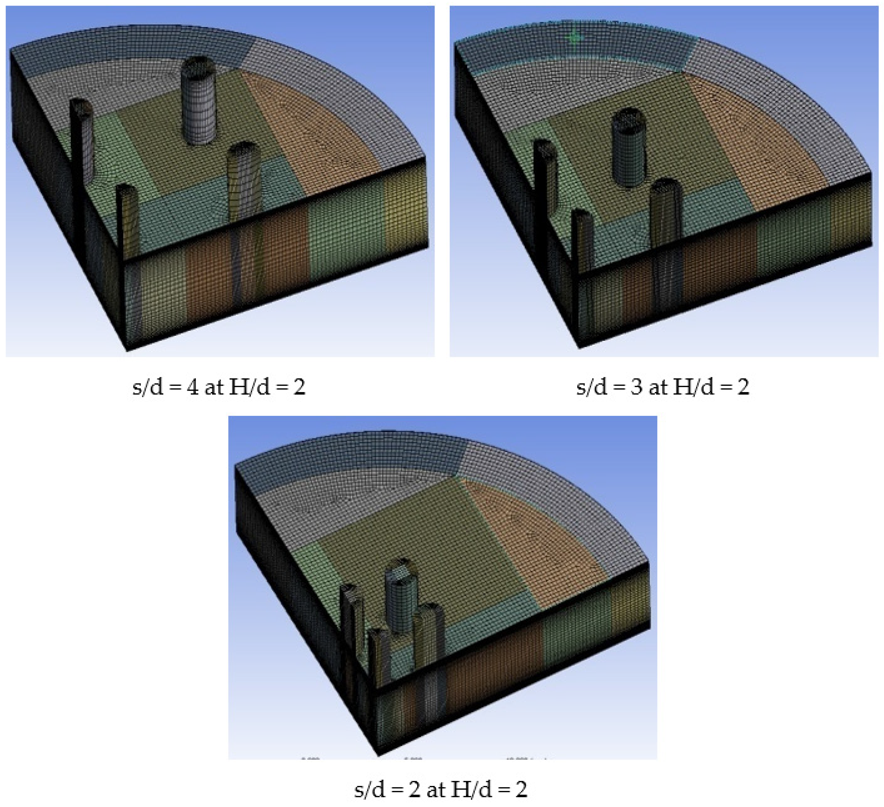
4.4. Meshing Model
4.5. Numerical Solution
4.6. Grid Independence Study and Grid Convergence Index Evaluation
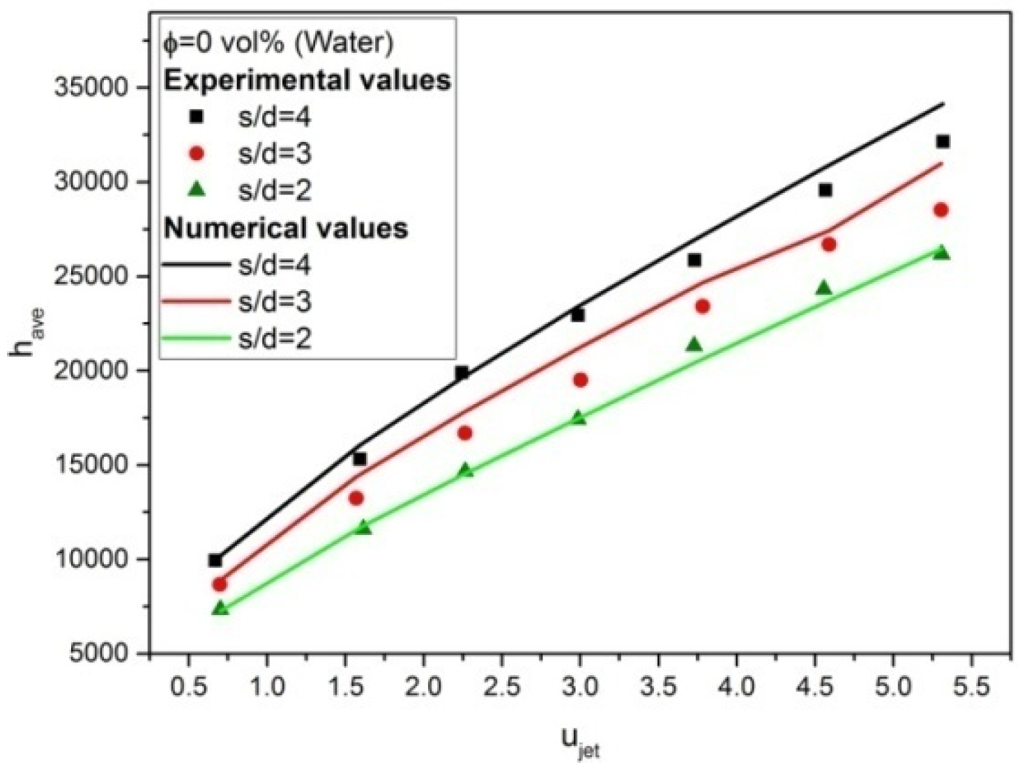
4.7. Model Validation
5. Results and Discussion
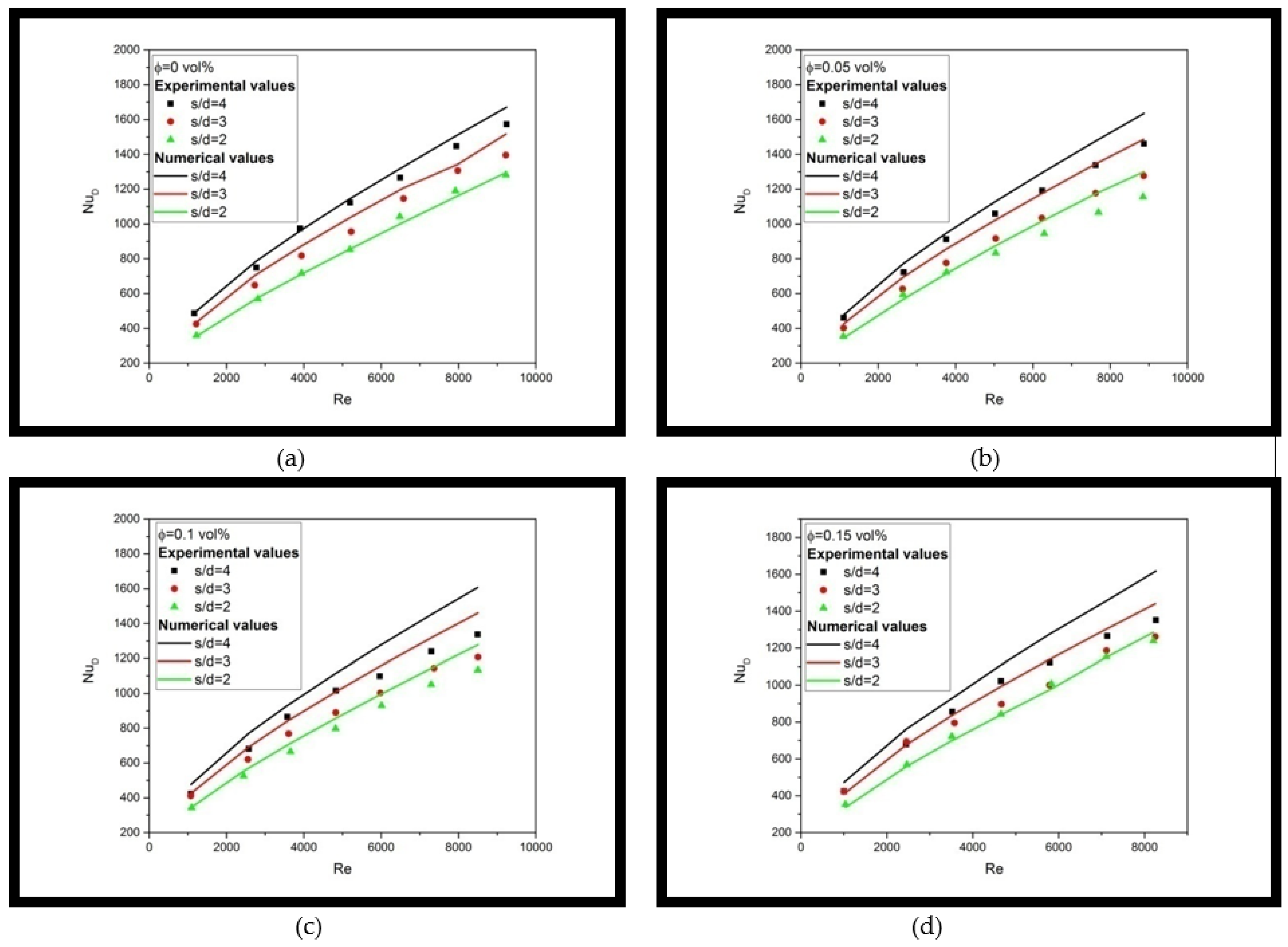
5.1. Heat Transfer Prediction on Multiple Jet Impingement Using Single Phase Model
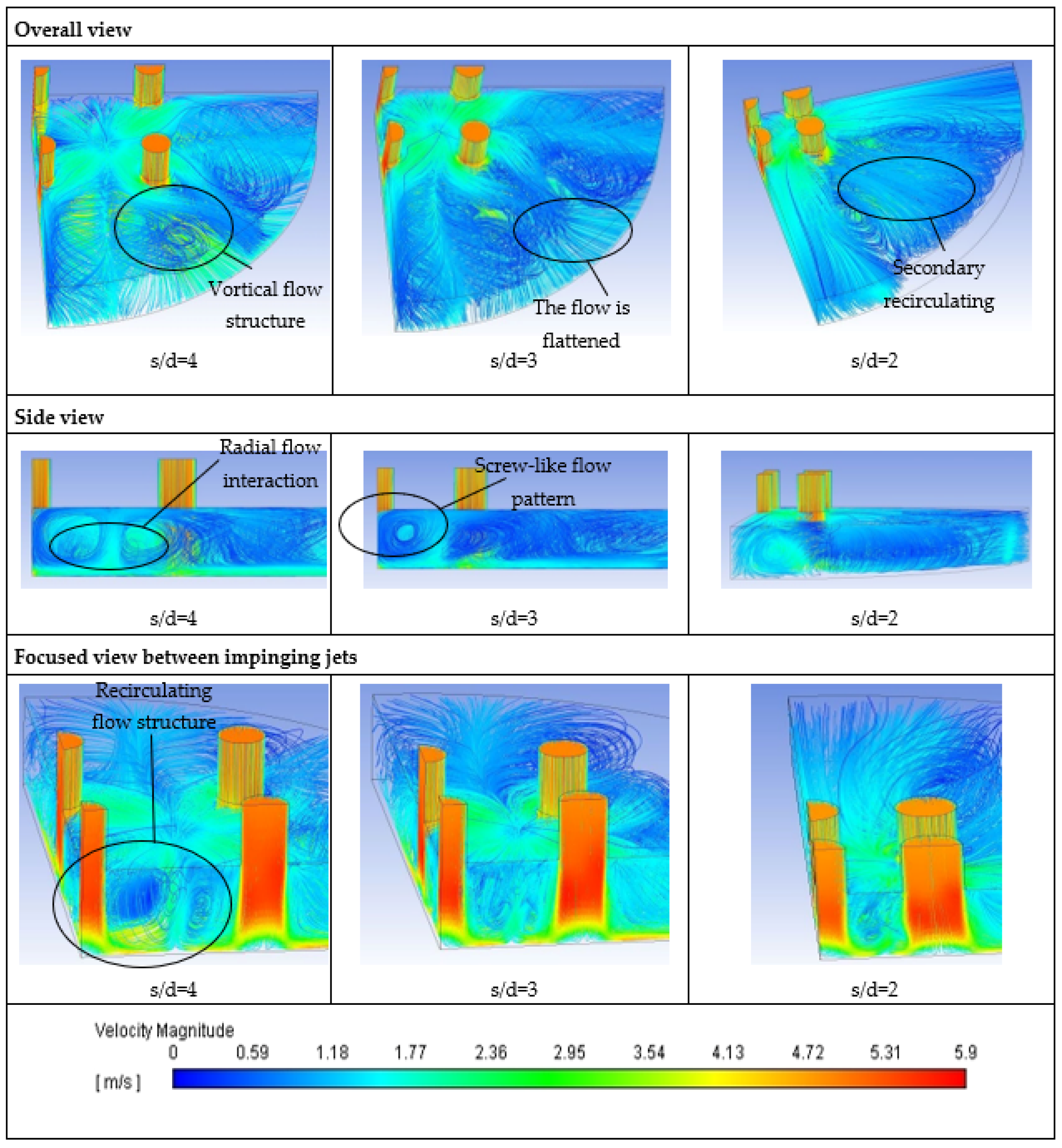
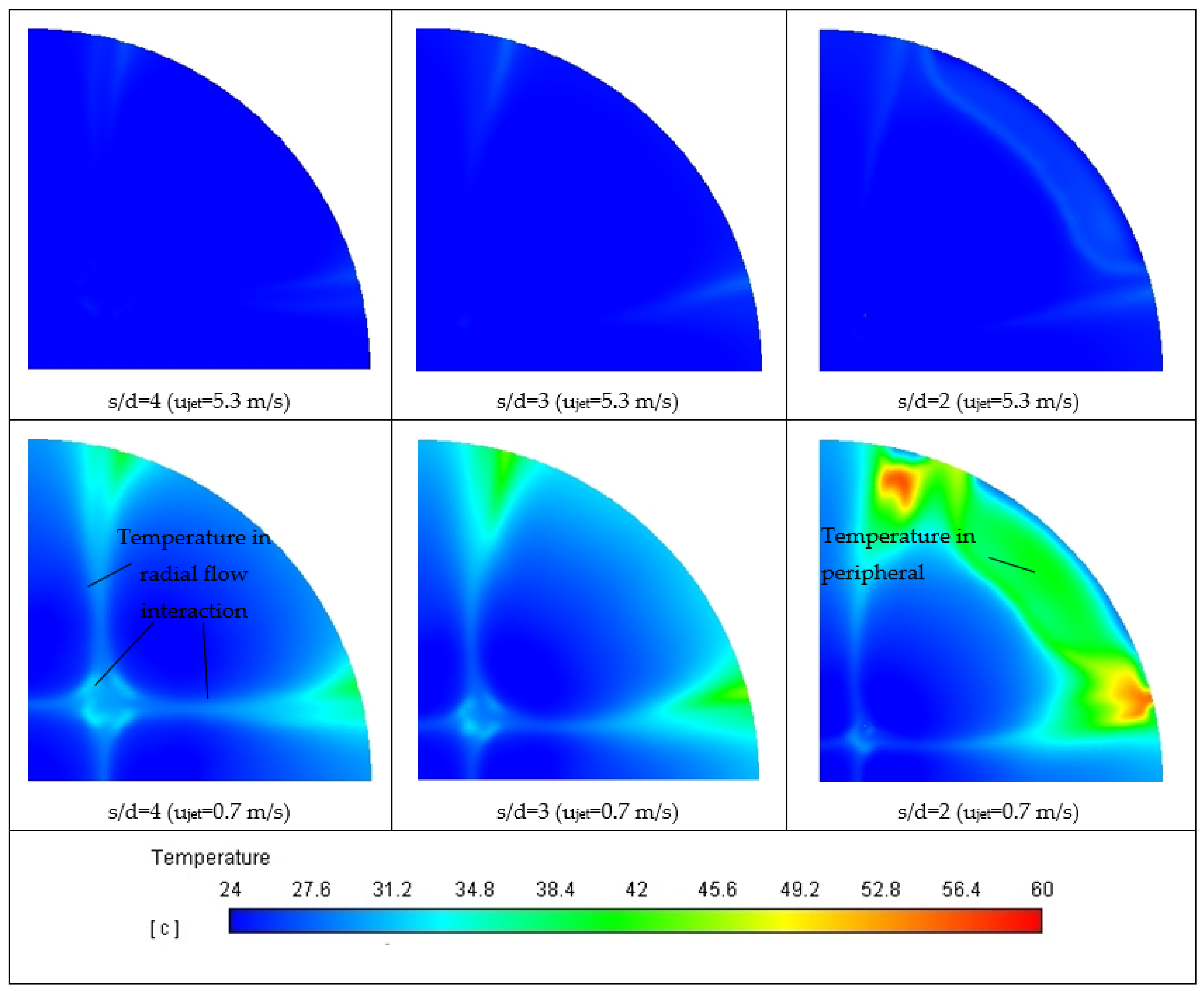
5.2. Fluid Flow Structure and Heat Transfer
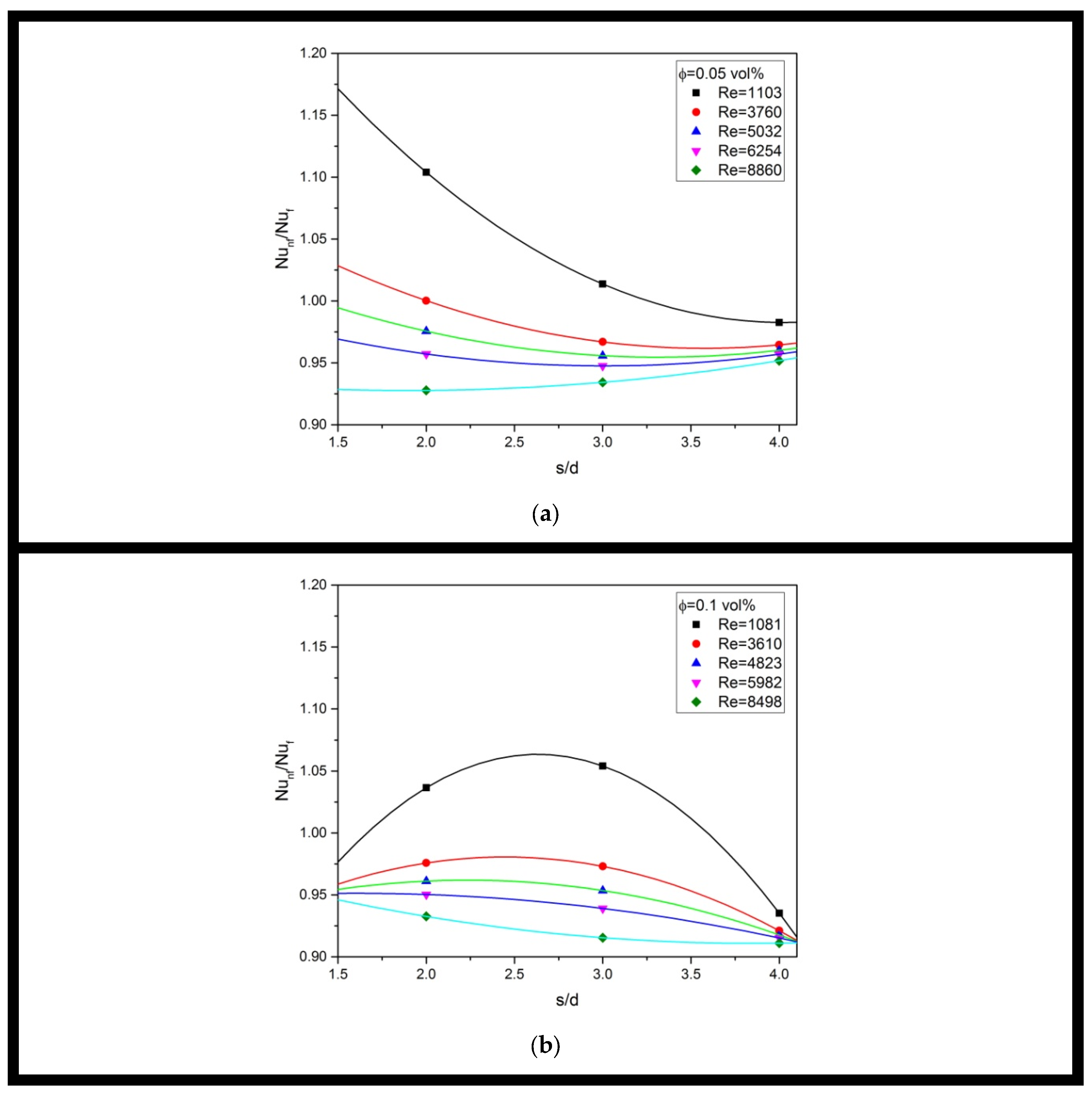
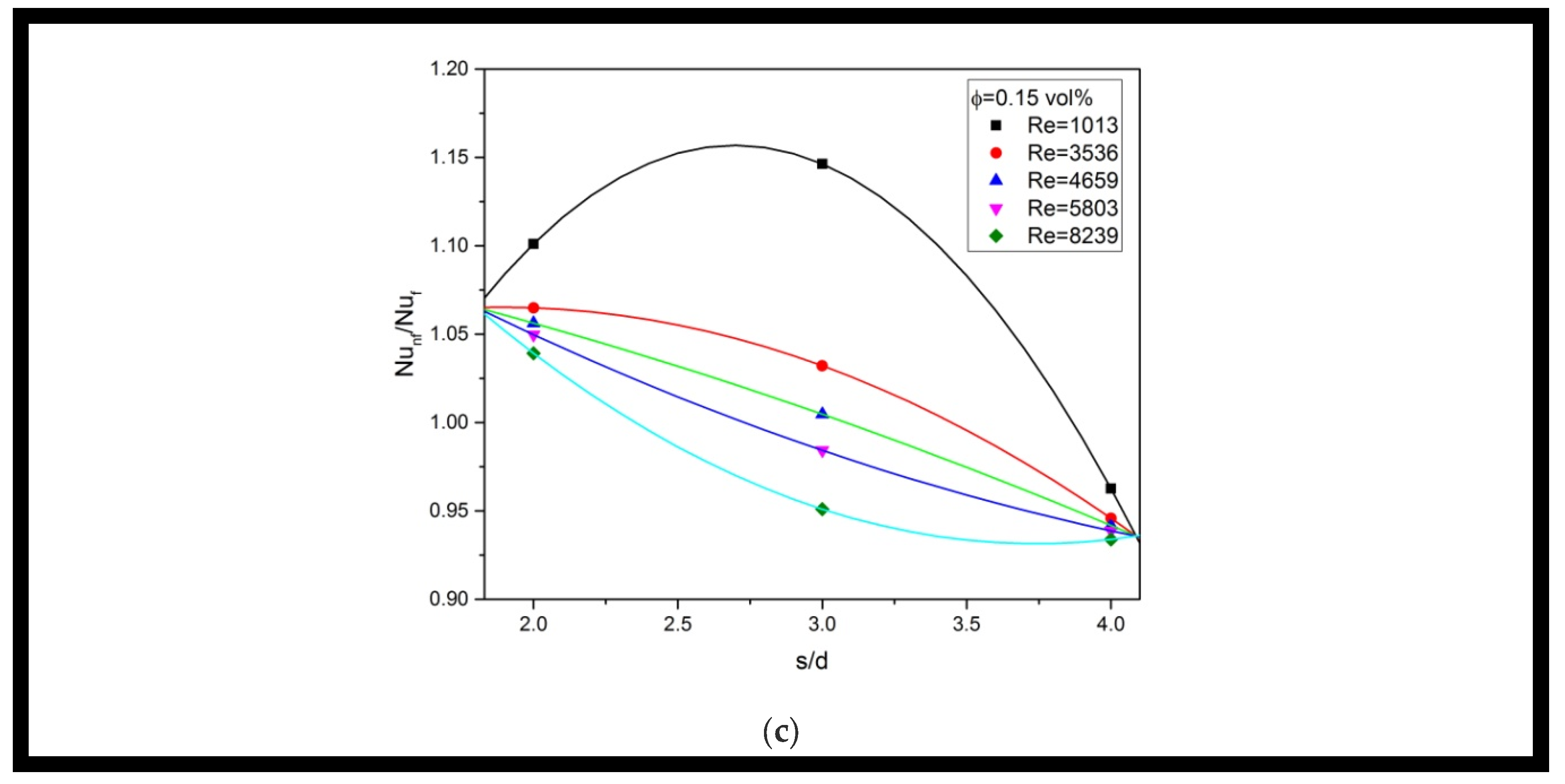
5.3. Nusselt Number Enhancement Ratio Results
5.4. Explanations on Heat Transfer Behavior of Multiple Jet Impingement Using Nanofluids
6. Conclusions
- The study shows that using a single-phase model to predict the heat transfer performance of nanofluid multiple jet impingement is limited. While the model can accurately predict the behavior of water, it deviates significantly from experimental results when nanofluids are used, particularly at high Reynolds numbers. This indicates that the model is unable to fully capture the effect of nanoparticles in the flow field. Thus, the author recommends that using multiple phase models can better account for the complex interaction between nanoparticles and the base fluid in multiple jet impingement flow.
- The flow pattern of multiple jet impingement is greatly affected by changes in the geometry, specifically the jet-to-jet spacing. The interaction between radial flows from adjacent jets generates recirculating flow structures, which become smaller as the jet-to-jet spacing decreases. At a dimension ratio of s/d = 2, the loss of momentum in the diagonal flow outside the impinging jet zone causes the formation of a secondary recirculating flow structure, leading to a significant temperature escalation at the target surface’s edge. The screw-like flow structure leaving the impinging jet zone also becomes smaller as the jet-to-jet spacing decreases, resulting in a faster exit of the fluid from the impinging jet zone. These changes in flow pattern have a significant impact on heat transfer behavior, leading to a reduction in the Nusselt number at smaller dimension ratios s/d under the same Reynolds number for water and all nanofluids (0.05, 0.1, and 0.15 vol%).
- The study evaluated the heat transfer behavior of multiple jet impingement using MgO-water nanofluid by analyzing the Nusselt number enhancement ratio (Nunf/Nuf) under different Reynolds numbers, dimension ratio s/d, and nanoparticle concentrations. The results show that using nanofluids for multiple jet impingement at a high Reynolds number regime and using a large jet-to-jet spacing is not beneficial. An optimum Nunf/Nuf of 1.15 was achieved using a 0.15 vol% nanofluid with an intermediate dimension ratio s/d of 3 under the lowest Reynolds number of 1013. The study concludes that the nanofluid can enhance heat transfer at a small jet-to-jet spacing using a high particle volume fraction under a low Reynolds number.
- The present paper used numerical simulation to confirm the existence of recirculation and vortical flow structures in multiple jet impingement, which supports the previous descriptions by Nguyen et al. [4] and Senkal and Torri [23] on nanofluid heat transfer. However, those previous studies did not consider the effects of Reynolds number and jet-to-jet spacing, which the present paper addressed to further explain the heat transfer behavior of multiple jet impingement using nanofluid.
- The recirculating and vortical flow structure in multiple jet impingement increases the collision rate of nanoparticles and promotes nanoparticle aggregation, reducing convective heat transfer and decreasing the Nusselt number enhancement ratio as Reynolds number increases. Using a high nanoparticle volume fraction enhances thermal dispersion and accelerates energy exchange, but the performance depends on geometrical configuration. Multiple jet impingement with a large dimension ratio has the worst heat transfer performance due to a thick thermal boundary layer caused by the entrapped nanofluid heating faster, while decreasing jet-to-jet spacing allows entrapped hot nanofluids to leave quickly and improves heat transfer performance.
Author Contributions
Funding
Data Availability Statement
Acknowledgments
Conflicts of Interest
Nomenclature
| List of symbols | |
| Cp | Specify heat capacity J/(kg K) |
| Cμ | Empirical constant of turbulent model |
| D | Diameter of target surface (mm) |
| Dω | Cross-diffusion term (kg m−3s−1) |
| d | Nozzle diameter (mm) |
| dh | Hydraulic diameter (mm) |
| E | Total energy (J) |
| F2 | Blending function |
| f | Dependent variable |
| Gk | Generation of turbulent kinetic energy (J m−3 s−1) |
| Gω | Gereration of specific rate of dissipation (kg m−3 s−1) |
| g | Gravitational acceleration (m/s2) |
| H | Nozzle-to-plate distance (mm) |
| h | Heat transfer coefficient (W/m2 K) |
| I | Turbulent intensity (%) |
| k | Thermal conductivity (W/mK) |
| k | Turbulent kinetic energy (J/kg) |
| m | Mass (g) |
| Mass flow rate (kg/s) | |
| Njet | Number of jets |
| NP | Dispersed nanoparticle |
| Nu | Nusselt number |
| NuD | Nusselt number based on target surface diameter |
| Pr | Prandtl number |
| p | Static pressure (Pa) |
| Qv | Volumetric flow rate (m3/s) |
| q | Heat flux (W/m2) |
| Heat flux (W/cm2) | |
| Red | Reynolds number based on nozzle diameter |
| Redh | Reynolds number based on hydraulic diameter |
| ReH | Reynolds number based on channel gap height |
| Redi | Reynolds number based on impinged jet diameter |
| S | Modulus of the mean rate-of-strain tensor |
| s | Jet-to-jet spacing (mm) |
| T | Temperature (°C) |
| Ts | Average temperature of target surface (°C) |
| Tjet | Temperature of impinging jet (°C) |
| t | Time (s) |
| U | Uncertainty |
| u | Velocity (m/s) |
| Velocity vector (m/s) | |
| wi | Independent variable |
| Yk | Dissipation of k (J m−3 s−1) |
| Yω | Dissipation of ω (kg m−3 s−1) |
| z | z-coordinate (m) |
| Greek symbols | |
| α* | Model coefficient |
| αi | Model constant |
| Γk | Effective diffusivity of k (Pa.s) |
| Γω | Effective diffusivity of ω (Pa.s) |
| μ | Viscosity (Pa.s) |
| ρ | Density (kg/m3) |
| σk | Prantl number of k |
| σω | Prantl number of ω |
| τ | Stress tensor (N/m2) |
| ϕ | Nanoparticle volume fraction (vol%) |
| φ | Nanoparticle mass fraction (wt%) |
| ψ | Nanoparticles mass per unit volume (kg/m3) |
| ω | Specific turbulent dissipation rate (1/s) |
| Subscript | |
| Al | Aluminium alloy |
| ave | Average value |
| f | Base fluid |
| i | Direction i |
| j | Direction j |
| jet | Jet |
| nf | Nanofluid |
| p | Nanoparticle |
| t | Turbulent flow |
References
- Robinson, A.; Schnitzler, E. An experimental investigation of free and submerged miniature liquid jet array impingement heat transfer. Exp. Therm. Fluid Sci. 2007, 32, 1–13. [Google Scholar] [CrossRef]
- Fabbri, M.; Dhir, V.K. Optimized heat transfer for high power electronic cooling using arrays of microjets. J. Heat Transf. 2005, 127, 760–769. [Google Scholar] [CrossRef]
- Roy, G.; Nguyen, C.T.; Lajoie, P.-R. Numerical investigation of laminar flow and heat transfer in a radial flow cooling system with the use of nanofluids. Superlattices Microstruct. 2004, 35, 497–511. [Google Scholar] [CrossRef]
- Nguyen, C.; Laplante, G.; Cury, M.; Simon, G. Experimental Investigation of Impinging Jet Heat Transfer and Erosion Effect Using Al2O3-Water Nanofluid. In Proceedings of the 6th IASME/WSEAS International Conference on Fluid Mechanics and Aerodynamics (FMA’08), Rhodes, Greece, 20–22 August 2008. [Google Scholar]
- Nguyen, C.T.; Galanis, N.; Polidori, G.; Fohanno, S.; Popa, C.V.; Le Bechec, A. An experimental study of a confined and submerged impinging jet heat transfer using Al2O3-water nanofluid. Int. J. Therm. Sci. 2009, 48, 401–411. [Google Scholar] [CrossRef]
- Gherasim, I.; Roy, G.; Nguyen, C.T.; Vo-Ngoc, D. Experimental investigation of nanofluids in confined laminar radial flows. Int. J. Therm. Sci. 2009, 48, 1486–1493. [Google Scholar] [CrossRef]
- Li, Q.; Xuan, Y.; Yu, F.; Tan, J. Experimental Investigation of Submerged Impinging Jet Using Cu-Water Nanofluid. In Proceedings of the 2010 14th International Heat Transfer Conference, Washington, DC, USA, 8–13 August 2010; pp. 469–473. Available online: https://asmedigitalcollection.asme.org/IHTC/proceedings-abstract/IHTC14/469/350716 (accessed on 1 March 2011).
- Li, Q.; Xuan, Y.; Yu, F. Experimental investigation of submerged single jet impingement using Cu–water nanofluid. Appl. Therm. Eng. 2012, 36, 426–433. [Google Scholar] [CrossRef]
- Zhou, M.; Xia, G.; Chai, L. Heat transfer performance of submerged impinging jet using silver nanofluids. Heat Mass Transf. 2015, 51, 221–229. [Google Scholar] [CrossRef]
- Zeitoun, O.; Ali, M. Nanofluid impingement jet heat transfer. Nanoscale Res. Lett. 2012, 7, 1–13. [Google Scholar] [CrossRef]
- Zeitoun, O.; Ali, M.; Al-Ansary, H. The effect of particle concentration on cooling of a circular horizontal surface using nanofluid jets. Nanoscale Microscale Thermophys. Eng. 2013, 17, 154–171. [Google Scholar] [CrossRef]
- Jaberi, B.; Yousefi, T.; Farahbakhsh, B.; Saghir, M. Experimental investigation on heat transfer enhancement due to Al2O3–water nanofluid using impingement of round jet on circular disk. Int. J. Therm. Sci. 2013, 74, 199–207. [Google Scholar] [CrossRef]
- Chang, T.-B.; Yang, Y.-K. Heat transfer performance of jet impingement flow boiling using Al2O3-water nanofluid. J. Mech. Sci. Technol. 2014, 28, 1559–1566. [Google Scholar] [CrossRef]
- Teamah, M.A.; Dawood, M.M.K.; Shehata, A. Numerical and experimental investigation of flow structure and behavior of nanofluids flow impingement on horizontal flat plate. Exp. Therm. Fluid Sci. 2016, 74, 235–246. [Google Scholar] [CrossRef]
- Lv, J.; Hu, C.; Bai, M.; Zeng, K.; Chang, S.; Gao, D. Experimental investigation of free single jet impingement using SiO2-water nanofluid. Exp. Therm. Fluid Sci. 2017, 84, 39–46. [Google Scholar] [CrossRef]
- Lv, J.; Chang, S.; Hu, C.; Bai, M.; Wang, P.; Zeng, K. Experimental investigation of free single jet impingement using Al2O3-water nanofluid. Int. Commun. Heat Mass Transf. 2017, 88, 126–135. [Google Scholar] [CrossRef]
- Barewar, S.D.; Tawri, S.; Chougule, S.S. Heat transfer characteristics of free nanofluid impinging jet on flat surface with different jet to plate distance: An experimental investigation. Chem. Eng. Process. Process Intensif. 2019, 136, 1–10. [Google Scholar] [CrossRef]
- Kareem, Z.S.; Balla, H.H.; AbdulWahid, A.F. Heat transfer enhancement in single circular impingement jet by CuO-water nanofluid. Case Stud. Therm. Eng. 2019, 15, 100508. [Google Scholar] [CrossRef]
- Sorour, M.M.; El-Maghlany, W.M.; Alnakeeb, M.A.; Abbass, A.M. Experimental study of free single jet impingement utilizing high concentration SiO2 nanoparticles water base nanofluid. Appl. Therm. Eng. 2019, 160, 114019. [Google Scholar] [CrossRef]
- Amjadian, M.; Safarzadeh, H.; Bahiraei, M.; Nazari, S.; Jaberi, B. Heat transfer characteristics of impinging jet on a hot surface with constant heat flux using Cu2O–water nanofluid: An experimental study. Int. Commun. Heat Mass Transf. 2020, 112, 104509. [Google Scholar] [CrossRef]
- Balla, H.H.; Hashem, A.L.; Kareem, Z.S.; Abdulwahid, A.F. Heat transfer potentials of ZnO/water nanofluid in free impingement jet. Case Stud. Therm. Eng. 2021, 27, 101143. [Google Scholar] [CrossRef]
- Senkal, C.; Torii, S. Investigation on the Multiple Jet Impingement Heat Transfer Using Al2O3-Water Nanofluid. In Proceedings of the ASME 2013 International Technical Conference and Exhibition on Packaging and Integration of Electronic and Photonic Microsystems, Burlingame, CA, USA, 16–18 July 2013; p. V002T08A015. Available online: https://asmedigitalcollection.asme.org/InterPACK/proceedings-abstract/InterPACK2013/55768/V002T08A015/265822 (accessed on 20 January 2014).
- Tie, P.; Li, Q.; Xuan, Y. Heat transfer performance of Cu–water nanofluids in the jet arrays impingement cooling system. Int. J. Therm. Sci. 2014, 77, 199–205. [Google Scholar] [CrossRef]
- Senkal, C.; Torii, S. Thermal fluid flow transport phenomena in nanofluid jet array impingement. J. Flow Vis. Image Process. 2015, 22, 59–79. [Google Scholar] [CrossRef]
- Al-Zuhairy, R.C.; Kareem, Z.S.; Abdulhadi, A.A. Al2O3-water nanofluid heat transfer enhancement of a twin impingement jet. Case Stud. Therm. Eng. 2020, 19, 100626. [Google Scholar] [CrossRef]
- Darwish, A.M.; El-Kersh, A.-F.M.; El-Moghazy, I.M.; Elsheikh, M.N. Experimental and Numerical Study of Multiple Free Jet Impingement Arrays with Al2O3-Water Nanofluid. J. Adv. Res. Fluid Mech. Therm. Sci. 2020, 65, 230–252. [Google Scholar]
- Kolsi, L.; Selimefendigil, F.; Gasmi, H.; Alshammari, B.M. Conjugate Heat Transfer Analysis for Cooling of a Conductive Panel by Combined Utilization of Nanoimpinging Jets and Double Rotating Cylinders. Nanomaterials 2023, 13, 500. [Google Scholar] [CrossRef]
- Selimefendigil, F.; Öztop, H.F. Multijet impingement heat transfer under the combined effects of encapsulated-PCM and inclined magnetic field during nanoliquid convection. Int. J. Heat Mass Transf. 2023, 203, 123764. [Google Scholar] [CrossRef]
- Leslie, S.G. Cooling options and challenges of high power semiconductor modules. Electron. Cool. 2006, 12, 20. [Google Scholar]
- Loong, T.T.; Salleh, H.; Khalid, A.; Koten, H. Thermal performance evaluation for different type of metal oxide water based nanofluids. Case Stud. Therm. Eng. 2021, 27, 101288. [Google Scholar] [CrossRef]
- Esfe, M.H.; Saedodin, S.; Mahmoodi, M. Experimental studies on the convective heat transfer performance and thermophysical properties of MgO–water nanofluid under turbulent flow. Exp. Therm. Fluid Sci. 2014, 52, 68–78. [Google Scholar] [CrossRef]
- Motevasel, M.; Nazar, A.R.S.; Jamialahmadi, M. Experimental investigation of turbulent flow convection heat transfer of MgO/water nanofluid at low concentrations–Prediction of aggregation effect of nanoparticles. Int. J. Heat Technol. 2017, 35, 755–764. [Google Scholar] [CrossRef]
- Dabiri, E.; Bahrami, F.; Mohammadzadeh, S. Experimental investigation on turbulent convection heat transfer of SiC/W and MgO/W nanofluids in a circular tube under constant heat flux boundary condition. J. Therm. Anal. Calorim. 2018, 131, 2243–2259. [Google Scholar] [CrossRef]
- Ali, H.M.; Azhar, M.D.; Saleem, M.; Saeed, Q.S.; Saieed, A. Heat transfer enhancement of car radiator using aqua based magnesium oxide nanofluids. Therm. Sci. 2015, 19, 2039–2048. [Google Scholar] [CrossRef]
- Kadhim, Z.K.; Kassim, M.S.; Hassan, A.Y.A. Effect of (MGO) nanofluid on heat transfer characteristics for integral finned tube heat exchanger. Int. J. Mech. Eng. Technol. 2016, 7, 11–24. [Google Scholar]
- Sajid, M.U.; Ali, H.M.; Bicer, Y. Exergetic performance assessment of magnesium oxide–water nanofluid in corrugated minichannel heat sinks: An experimental study. Int. J. Energy Res. 2020, 46, 9985–10001. [Google Scholar] [CrossRef]
- Mohammadpour, J.; Lee, A. Investigation of nanoparticle effects on jet impingement heat transfer: A review. J. Mol. Liq. 2020, 316, 113819. [Google Scholar] [CrossRef]
- Abdullah, M.F.; Zulkifli, R.; Moria, H.; Najm, A.S.; Harun, Z.; Abdullah, S.; Ghopa, W.A.W.; Sulaiman, N.H. Assessment of TiO2 Nanoconcentration and Twin Impingement Jet of Heat Transfer Enhancement—A Statistical Approach Using Response Surface Methodology. Energies 2021, 14, 595. [Google Scholar] [CrossRef]
- Hanafi, N.S.M.; Ghopa, W.A.W.; Zulkifli, R.; Abdullah, S.; Harun, Z.; Mansor, M.R.A. Numerical simulation on the effectiveness of hybrid nanofluid in jet impingement cooling application. Energy Rep. 2022, 8, 764–775. [Google Scholar] [CrossRef]
- Abdullah, M.F.; Zulkifli, R.; Harun, Z.; Abdullah, S.; Ghopa, W.A.W.; Najm, A.S.; Sulaiman, N.H. Impact of the TiO2 Nanosolution Concentration on Heat Transfer Enhancement of the Twin Impingement Jet of a Heated Aluminum Plate. Micromachines 2019, 10, 176. [Google Scholar] [CrossRef]
- Etminan, A.; Harun, Z. Forced Convective Heat Transfer Analysis for Two-dimensional Slot Jet of Water-CuO Nanofluid. J. Kejuruteraan 2021, 33, 229–238. [Google Scholar] [CrossRef]
- Hasan, H.A.; Alquziweeni, Z.; Sopian, K. Heat transfer enhancement using nanofluids for cooling a Central Processing Unit (CPU) system. J. Adv. Res. Fluid Mech. Thermal Sci. 2018, 51, 145–157. [Google Scholar]
- Ewe, W.E.; Fudholi, A.; Sopian, K.; Solomin, E.; Yazdi, M.H.; Asim, N.; Fatima, N.; Pikra, G.; Sudibyo, H.; Fatriasari, W.; et al. Jet impingement cooling applications in solar energy technologies: Systematic literature review. Therm. Sci. Eng. Prog. 2022, 34, 101445. [Google Scholar] [CrossRef]
- Hashimoto, S.; Kurazono, K.; Yamauchi, T. Anomalous enhancement of convective heat transfer with dispersed SiO2 particles in ethylene glycol/water nanofluid. Int. J. Heat Mass Transf. 2020, 150, 119302. [Google Scholar] [CrossRef]
- Meriläinen, A.; Seppälä, A.; Saari, K.; Seitsonen, J.; Ruokolainen, J.; Puisto, S.; Rostedt, N.; Ala-Nissila, T. Influence of particle size and shape on turbulent heat transfer characteristics and pressure losses in water-based nanofluids. Int. J. Heat Mass Transf. 2013, 61, 439–448. [Google Scholar] [CrossRef]
- Sasidharan, S.J.K.; Krishnamurthy, N.P.; Mamat, R.; Loganathan, V.D.; Sathyamurthy, R. Synthesis, characterisation and thermo-physical investigations on magnesia nanoparticles dispersed in ethylene glycol–DI water (50:50). Micro Nano Lett. 2018, 13, 335–340. [Google Scholar] [CrossRef]
- Bishop, D.P.; Hexemer, R.L., Jr.; Donaldson, I.W. Aluminum alloy powder metal with high thermal conductivity. U.S. Patent 10,058,916, 28 August 2018. [Google Scholar]
- Kline, S.J. Describing uncertainty in single sample experiments. Mech. Eng. 1953, 75, 3–8. [Google Scholar]
- Stevens; Webb, B.W. Local heat transfer coefficients under an axisymmetric, single-phase liquid jet. J. Heat Transfer. 1991, 113, 71–78. [Google Scholar] [CrossRef]
- Ansys, Inc. ANSYS Fluent Theory Guide; ANSYS, Inc.: Canonsburg, PA, USA, 2013; p. 794. Available online: http://www.pmt.usp.br/academic/martoran/notasmodelosgrad/ANSYS%20Fluent%20Theory%20Guide%2015.pdf (accessed on 11 April 2023).
- Roache, P.J. Perspective: A method for uniform reporting of grid refinement studies. Fluids Eng. 1994, 116, 405–413. [Google Scholar] [CrossRef]


| Author | NP | Concentration | Jet Number | Jet’s Height | Jets’ Spacing | Reynold Number | Enhancement Ratio a |
|---|---|---|---|---|---|---|---|
| (A) Submerged jet impingement | |||||||
| [4] | Al2O3 | ϕ = 5 | Njet = 1 | 2 ≤ H ≤ 10 | - | 1700 ≤ Red ≤ 20,000 | hnf/hf = 1.72 b () |
| [5] | Al2O3 | ϕ = 2.8 and 6 | Njet = 1 | 2 ≤ H ≤ 10 | - | 3800 ≤ Red ≤ 88,000 | 0.53 ≤ hnf/hf ≤ 1.35 (Red) |
| [6] | Al2O3 | 2 ≤ ϕ ≤ 6 | Njet = 1 | H = 2 and 3 | - | 500 ≤ ReH ≤ 901 | 1.06 ≤ Nunf/Nuf ≤ 2.4 (ReH) |
| [7] | Cu | 1.5 ≤ ϕ ≤ 3 | Njet = 1 | 2 ≤ H ≤ 6 | - | 2000 ≤ Red ≤ 16,000 | 1 ≤ Nunf/Nuf ≤ 1.25 (Red) |
| [8] | Cu | 1.5 ≤ ϕ ≤ 3 | Njet = 1 | 1 ≤ H/d ≤ 3 | - | 2000 ≤ Red ≤ 16,000 | 1.13 ≤ hnf/hf ≤ 1.54 (Red) |
| [9] | Ag | 0.02 ≤ φ ≤ 0.13 | Njet = 7 d3 | H = 3 | s = 7 | 200 ≤ Red ≤ 800 | 1.08 ≤ Nunf/Nuf ≤ 1.81 (Red) |
| (B) Free surface jet impingement | |||||||
| [10] | Al2O3 | φ = 6.6 and 10 | Njet = 1 | H = 50 | - | 2500 ≤ Redi ≤ 24,000 | 0.82 ≤ Nunf/Nuf ≤ 2.21 (Red) |
| [11] | Al2O3 | φ = 6.6 and 10 | Njet = 1 | H = 50 | - | 2500 ≤ Redi ≤ 24,000 | 0.96 ≤ Nunf/Nuf ≤ 2.06 (Red) |
| [12] | Al2O3 | 0.0198 ≤ φ ≤ 0.08 | Njet = 1 | H = 48 | - | 4200 ≤ Red ≤ 8200 | 1.04 ≤ hnf/hf ≤ 1.48 (Red) |
| [13] | Al2O3 | 1 × 10⁻⁴ ≤ ϕ ≤ 0.01 | Njet = 1 | H = 10 | - | - | 0.8 ≤ hnf/hf ≤ 1.27 () |
| [14] | Al2O3 | 2 ≤ ϕ ≤ 10 | Njet = 1 | H/d = 3 | - | 3000 ≤ Red ≤ 32,000 | 1.02 ≤ Nunf/Nuf ≤ 1.67 (Red) |
| [15] | SiO2 | 1 ≤ ϕ ≤ 3 | Njet = 1 | 2 ≤ H/d ≤ 5 | - | 8000 ≤ Red ≤ 13,000 | 1.12 ≤ hnf/hf ≤ 1.76 (Red) |
| [16] | Al2O3 | 0.5 ≤ ϕ ≤ 2 | Njet = 1 | 2 ≤ H/d ≤ 5 | - | 8000 ≤ Red ≤ 13,000 | 1.10 ≤ hnf/hf ≤ 1.75 (Red) |
| [17] | ZnO | 0.02 ≤ ϕ ≤ 0.1 | Njet = 1 | 2 ≤ H/d ≤ 7.5 | - | 2192 ≤ Red ≤ 9241 | 1.17 ≤ hnf/hf ≤ 1.58 (Red) |
| [18] | CuO | 0.1 ≤ ϕ ≤ 0.3 | Njet = 1 | 40 ≤ H ≤ 70 | - | 1000 ≤ Red ≤ 8000 | 0.65 ≤ Nunf/Nuf ≤ 2.24 (Red) |
| [19] | SiO2 | 0.5 ≤ ϕ ≤ 8.5 | Njet = 1 | 0.5 ≤ H/d ≤ 8 | - | 2148 ≤ Red ≤ 40,004 | 0.96 ≤ Nunf/Nuf ≤ 2.51 c (Red) |
| [20] | Cu2O | 0.03 ≤ ϕ ≤ 0.07 | Njet = 1 | - | - | 7330 ≤ Red ≤ 11,082 | 1.2 ≤ hnf/hf ≤ 1.31 (Red) |
| [21] | ZnO | 0.1 ≤ ϕ ≤ 0.5 | Njet = 1 | 2 ≤ H/dh ≤ 8 | - | 5000 ≤ Redh ≤ 17,500 | 1.3 ≤ Nunf/Nuf ≤ 2.27 (Redh) |
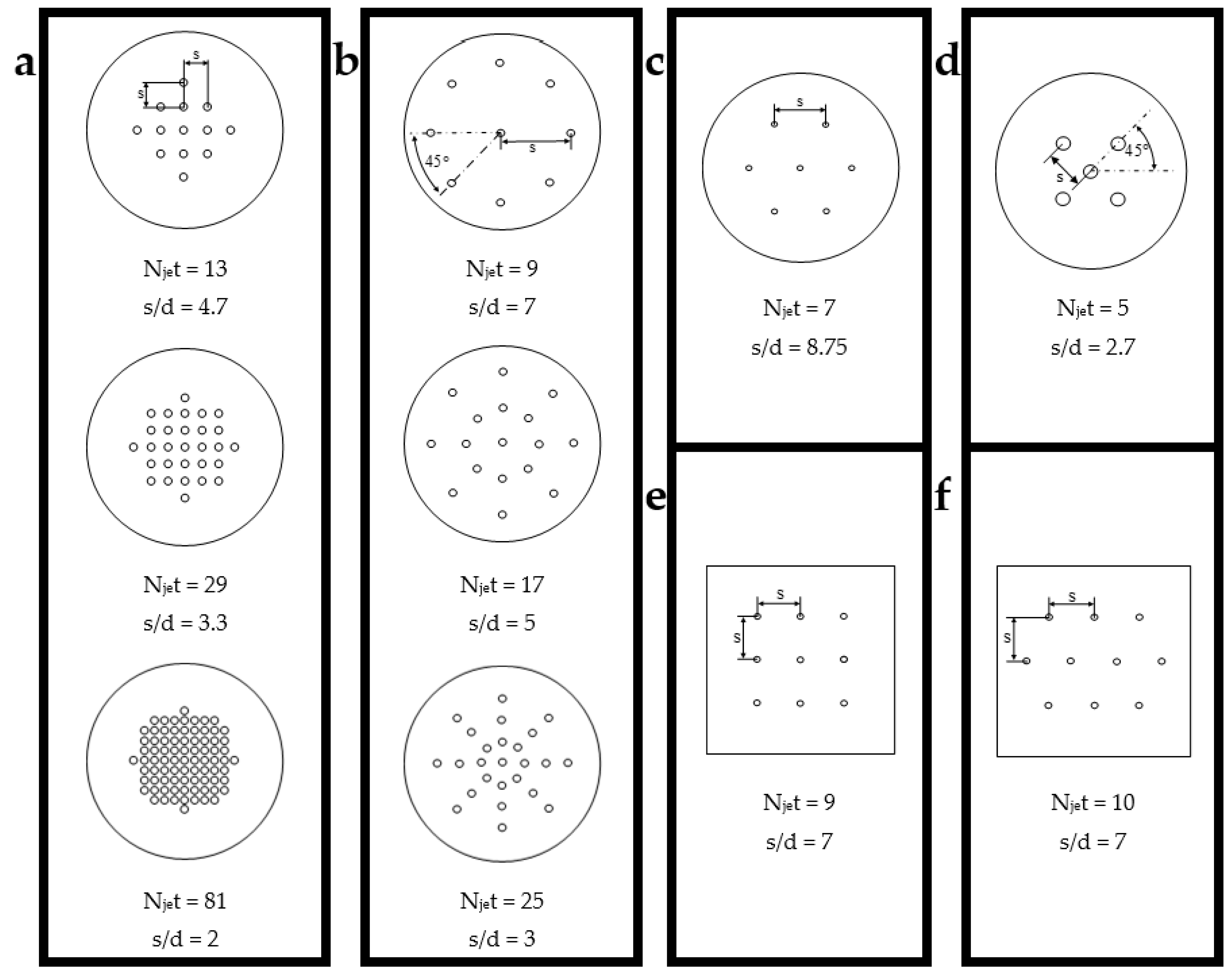
| [22] | Al2O3 | 2 ≤ ϕ ≤ 6 | 13 < Njet < 81 d1 | 2 ≤ H/d ≤ 17 | 3 ≤ s/d ≤ 7 | 2000 ≤ Red ≤ 10,000 | 2.13 ≤ Nunf/Nuf ≤ 5.98 (Red) |
| [23] | Cu | 0.17 ≤ ϕ ≤ 0.68 | Njet = 5 d4 | H = 15 | s = 4 | 4000 ≤ Red ≤ 10,000 | 0.93 ≤ hnf/hf ≤ 1.15 (Qv) |
| [24] | Al2O3 | 0.5 ≤ ϕ ≤ 4.9 | 9 < Njet < 17 d2 | H/d = 12.33 | 3 ≤ s/d ≤ 7 | 1280 ≤ Red ≤ 6500 | 0.74 ≤ Nunf/Nuf ≤ 1.04 (Red) |
| [25] | Al2O3 | 0.05 ≤ ψ ≤ 0.25 | Njet = 2 | 4 ≤ H/d ≤ 7 | - | 400 ≤ Red ≤ 2000 | 1.21 ≤ Nunf/Nuf ≤ 3.14 (Red) |
| [26] | Al2O3 | 5 ≤ ϕ ≤ 10 | Njet = 9 d5 and 10 d6 | 10 ≤ H/d ≤ 40 | s/d = 7 | 5600 ≤ Red ≤ 33,610 | 1.38 ≤ Nunf/Nuf ≤ 3.3 (Red) |
| Properties | Unit | Value |
|---|---|---|
| ρ | kg/m3 | 3585 |
| Cp | J/(kg K) | 903 |
| k | W/(mK) | 48.4 |
| Volume Fraction (%) | k (W m−1 k−1) | μ (Pa s) | ρ (kg/m3) | Cp (J kg−1 k−1) |
|---|---|---|---|---|
| 0 | 0.609 | 0.000912 | 997.32 | 4180.14 |
| 0.05 | 0.620 | 0.000950 | 998.61 | 4174.26 |
| 0.1 | 0.623 | 0.000992 | 999.91 | 4168.39 |
| 0.15 | 0.629 | 0.00102 | 1001.20 | 4162.54 |
| wi | Instrument | Smallest Reading | Uwi |
|---|---|---|---|
| d | Mitutoyo Digital Caliper | 1.5 mm | ±1.6% |
| T | PicoLog TC-08 | 24 °C | ±0.2% |
| ΔT | ΔT = Ts − Tjet | 1.2 °C | ±3% |
| dT/dz | - | 148 °C/m | ±0.8% |
| Qv | FS200A flow sensor | 1.6 LPM | ±2.15% |
| mf | WLC mass balance | 200 g | ±0.05% |
| mp | MS104TS mass balance | 0.36 g | ±0.03% |
| k | KD2 PRO analyzer | 0.6 W/(m k) | ±5% |
| μ | SV-10 viscometer | 0.912 mPa s | ±1% |
| Models | Grid Level | Number of Elements | NuD | Deviation between Grid Levels | GCI |
|---|---|---|---|---|---|
| s/d = 4 | Coarse | 157,114 | 1664.297 | - | - |
| Fine | 385,543 | 1670.69 | 0.39% | 0.24% | |
| Very fine | 782,680 | 1712.388 | 2.50% | 3.3% | |
| s/d = 3 | Coarse | 156,410 | 1496.977 | - | - |
| Fine | 388,250 | 1516.461 | 1.30% | 1.2% | |
| Very fine | 771,654 | 1558.061 | 2.74% | 4.6% | |
| s/d = 2 | Coarse | 159,450 | 1328.039 | - | - |
| Fine | 398,042 | 1294.999 | −2.50% | 0.14% | |
| Very fine | 777,894 | 1290.181 | −0.37% | 0.6% |
Disclaimer/Publisher’s Note: The statements, opinions and data contained in all publications are solely those of the individual author(s) and contributor(s) and not of MDPI and/or the editor(s). MDPI and/or the editor(s) disclaim responsibility for any injury to people or property resulting from any ideas, methods, instructions or products referred to in the content. |
© 2023 by the authors. Licensee MDPI, Basel, Switzerland. This article is an open access article distributed under the terms and conditions of the Creative Commons Attribution (CC BY) license (https://creativecommons.org/licenses/by/4.0/).
Share and Cite
Tang, T.L.; Salleh, H.; Sadiq, M.I.; Mohd Sabri, M.A.; Ahmad, M.I.M.; Ghopa, W.A.W. Experimental and Numerical Investigation of Flow Structure and Heat Transfer Behavior of Multiple Jet Impingement Using MgO-Water Nanofluids. Materials 2023, 16, 3942. https://doi.org/10.3390/ma16113942
Tang TL, Salleh H, Sadiq MI, Mohd Sabri MA, Ahmad MIM, Ghopa WAW. Experimental and Numerical Investigation of Flow Structure and Heat Transfer Behavior of Multiple Jet Impingement Using MgO-Water Nanofluids. Materials. 2023; 16(11):3942. https://doi.org/10.3390/ma16113942
Chicago/Turabian StyleTang, Tsz Loong, Hamidon Salleh, Muhammad Imran Sadiq, Mohd Anas Mohd Sabri, Meor Iqram Meor Ahmad, and Wan Aizon W. Ghopa. 2023. "Experimental and Numerical Investigation of Flow Structure and Heat Transfer Behavior of Multiple Jet Impingement Using MgO-Water Nanofluids" Materials 16, no. 11: 3942. https://doi.org/10.3390/ma16113942
APA StyleTang, T. L., Salleh, H., Sadiq, M. I., Mohd Sabri, M. A., Ahmad, M. I. M., & Ghopa, W. A. W. (2023). Experimental and Numerical Investigation of Flow Structure and Heat Transfer Behavior of Multiple Jet Impingement Using MgO-Water Nanofluids. Materials, 16(11), 3942. https://doi.org/10.3390/ma16113942