
Effect of the Laying Order of Core Layer Materials on the Sound-Insulation Performance of High-Speed Train Carbody


Abstract
1. Introduction
2. Simulation Study on the Effect of Core Layer Material Laying Order on Sandwich Composite Panel Sound Insulation
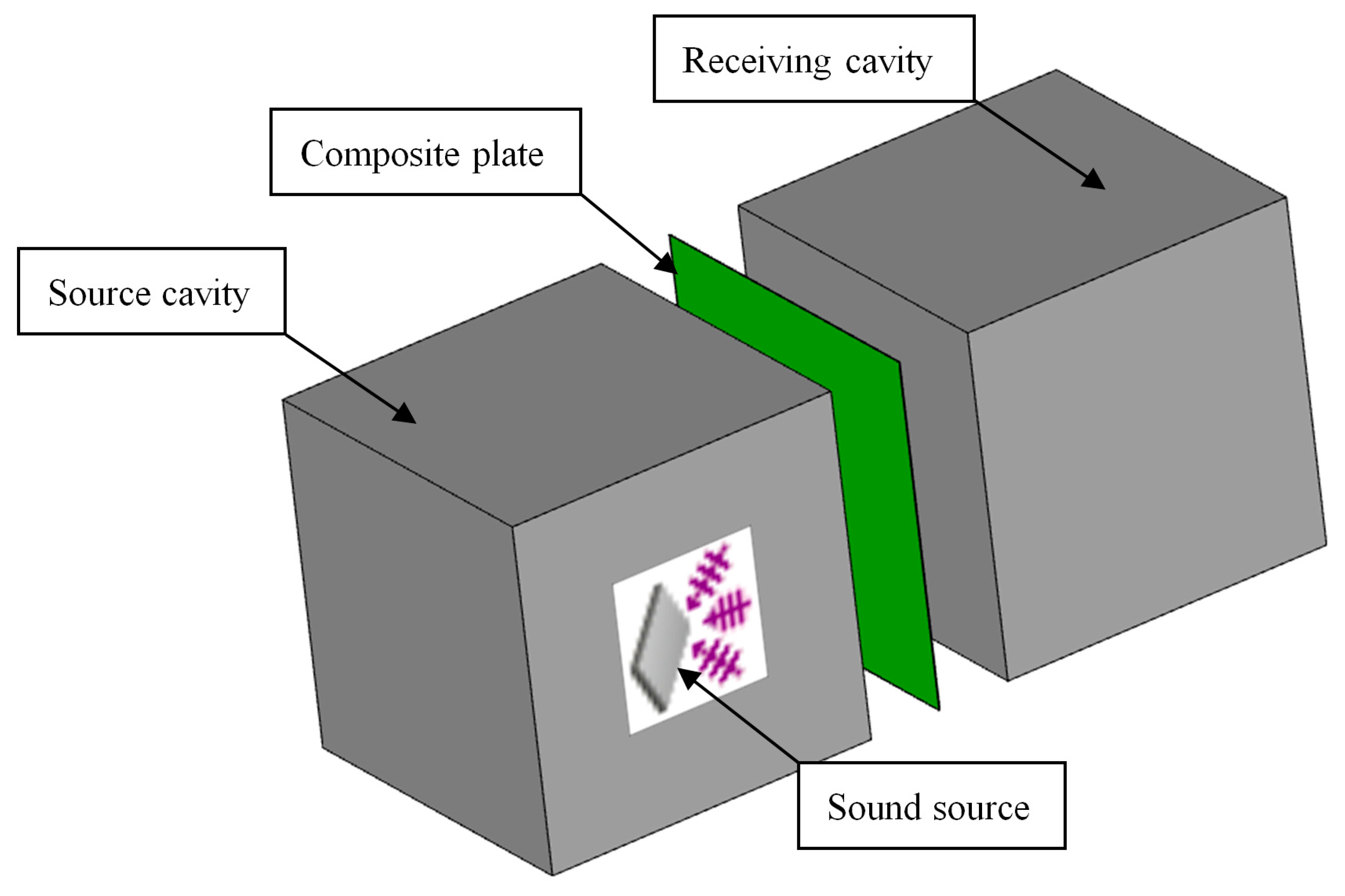
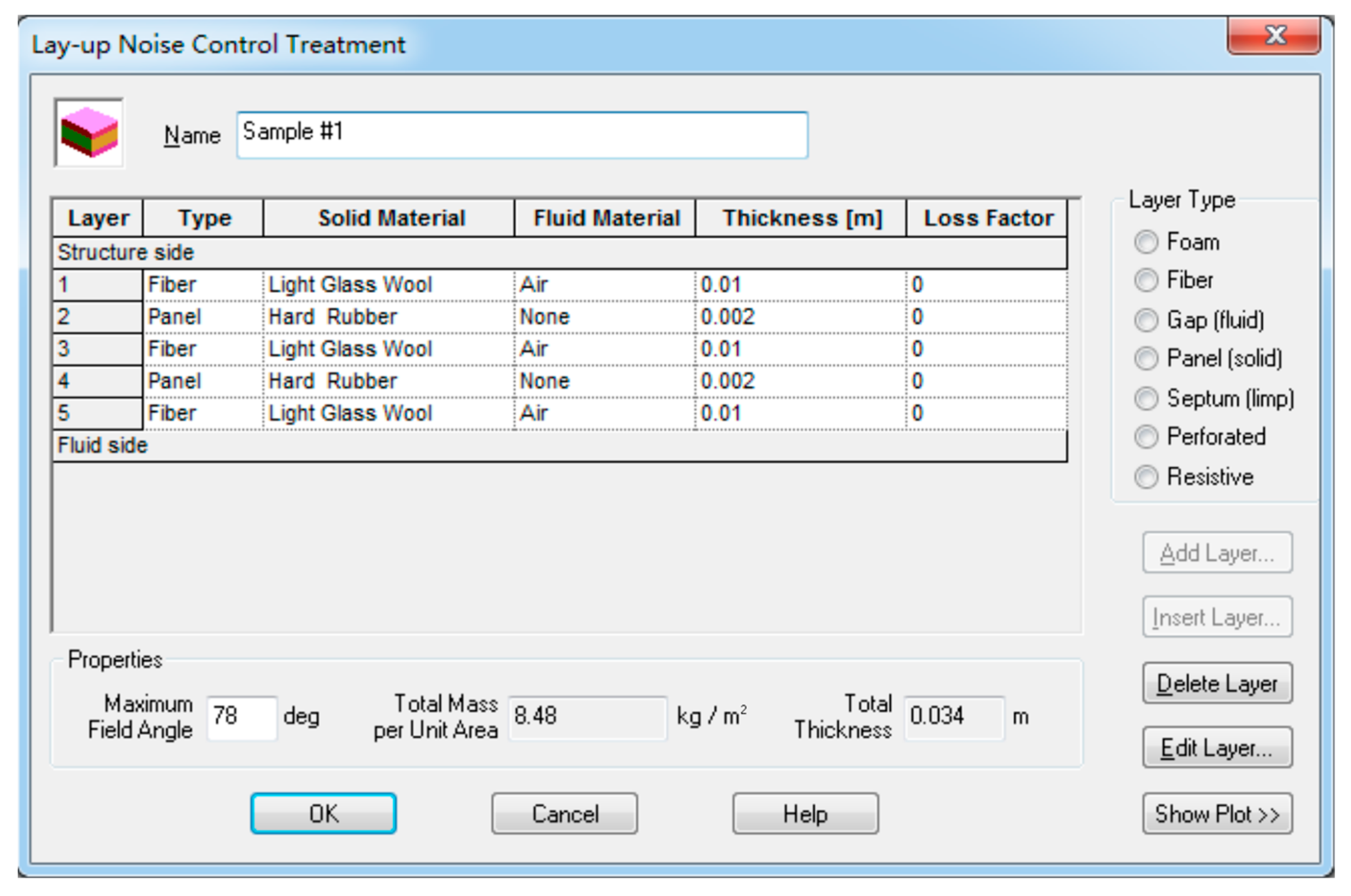
2.1. Sound Insulation Prediction Model
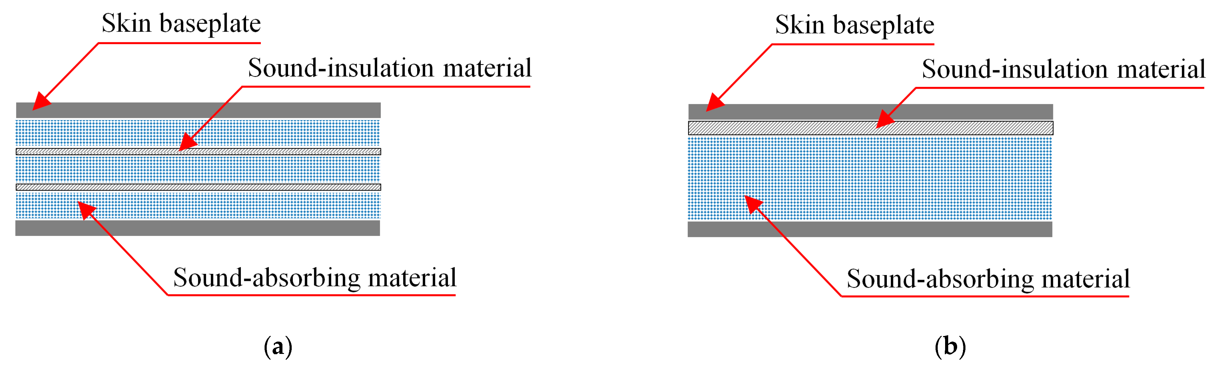
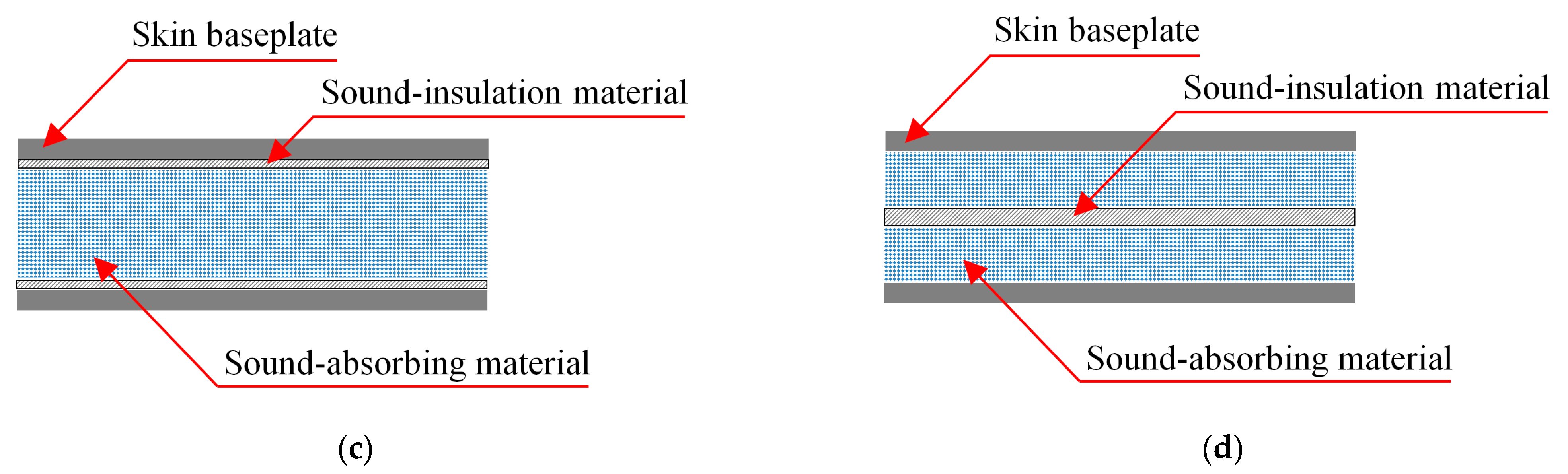
2.2. Research Schemes and Results Analysis
3. Test Verification
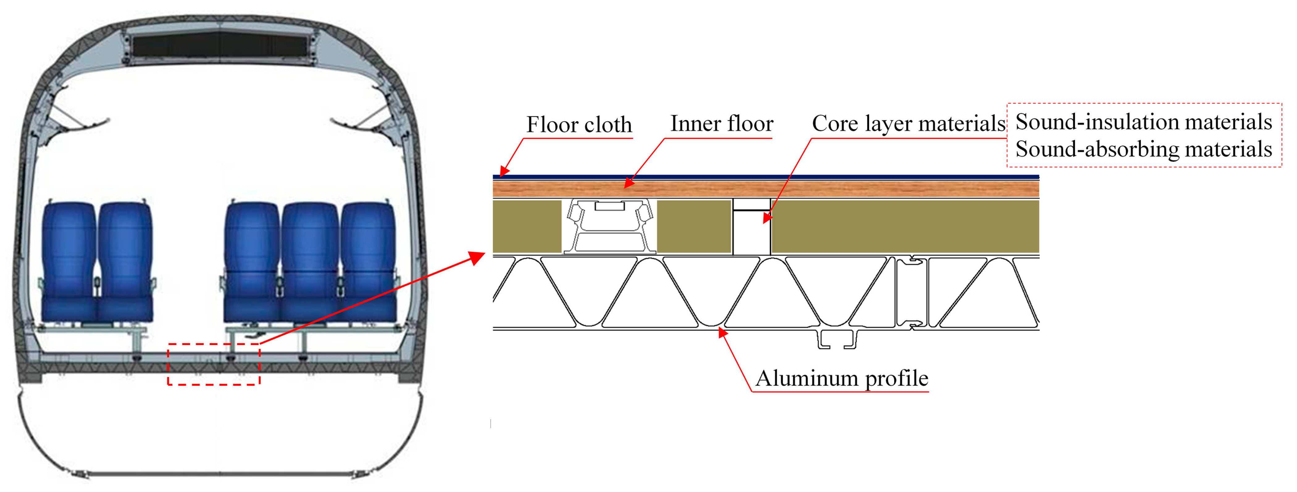
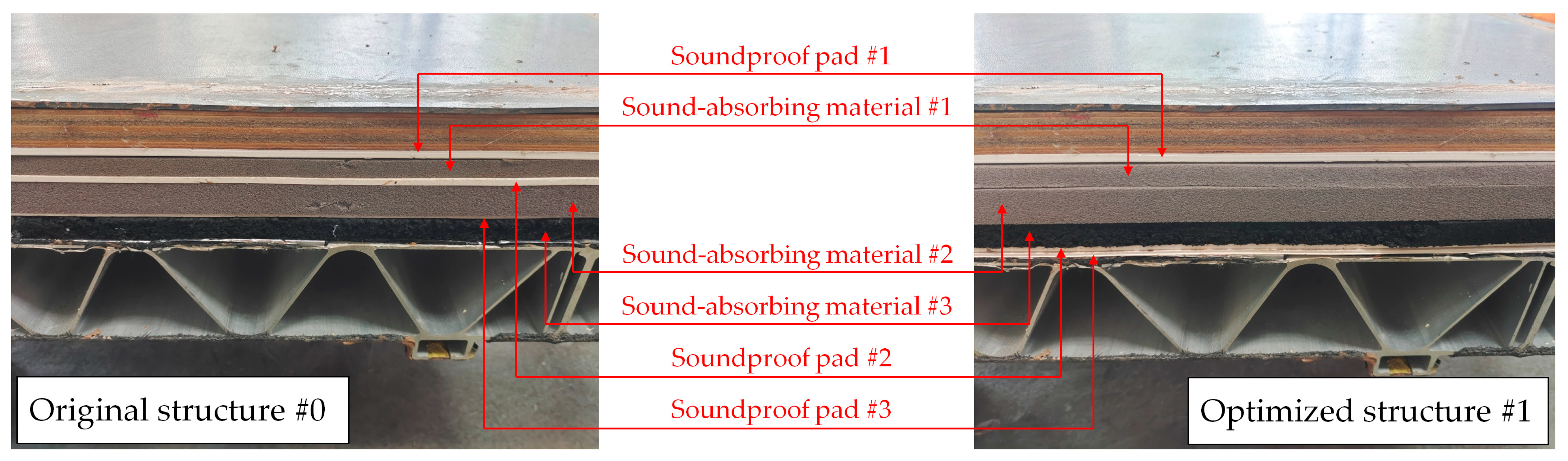
4. Optimization Design of Floor Sound Insulation for High-Speed Train
5. Conclusions
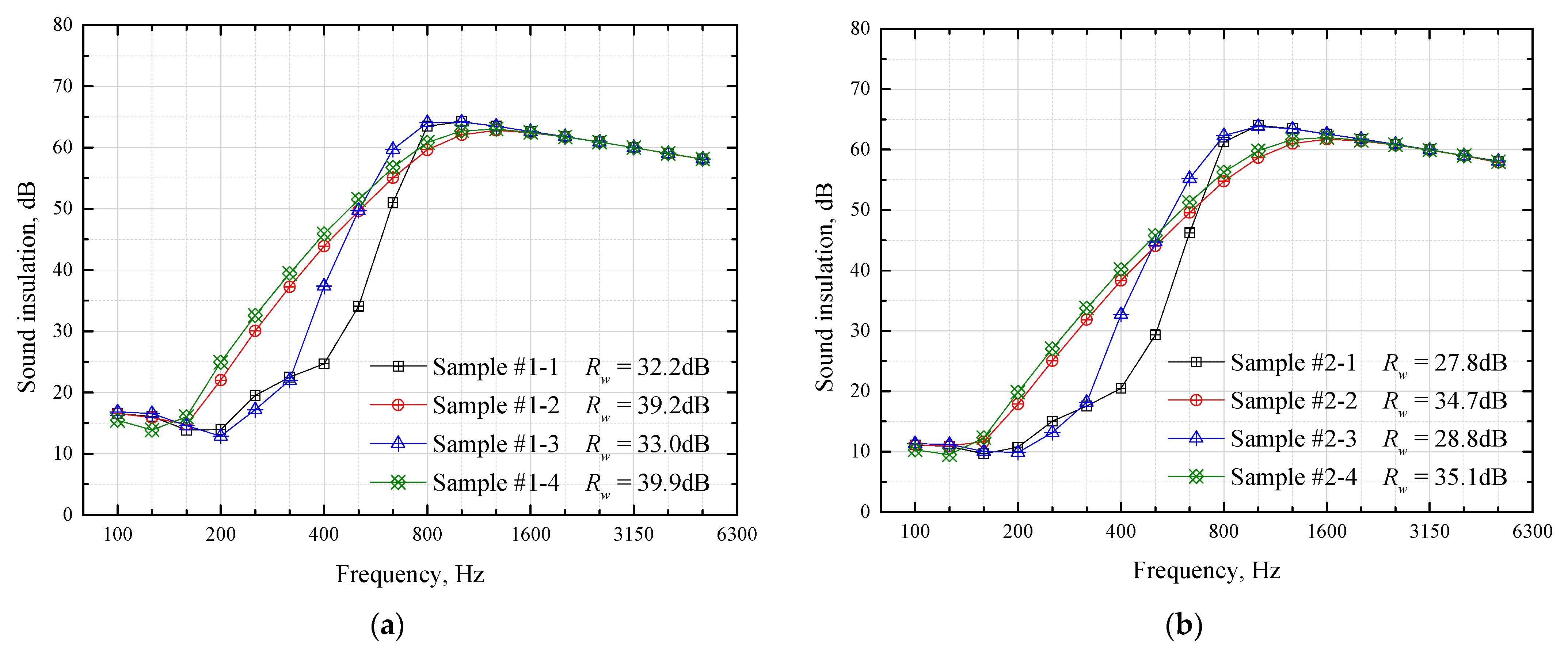
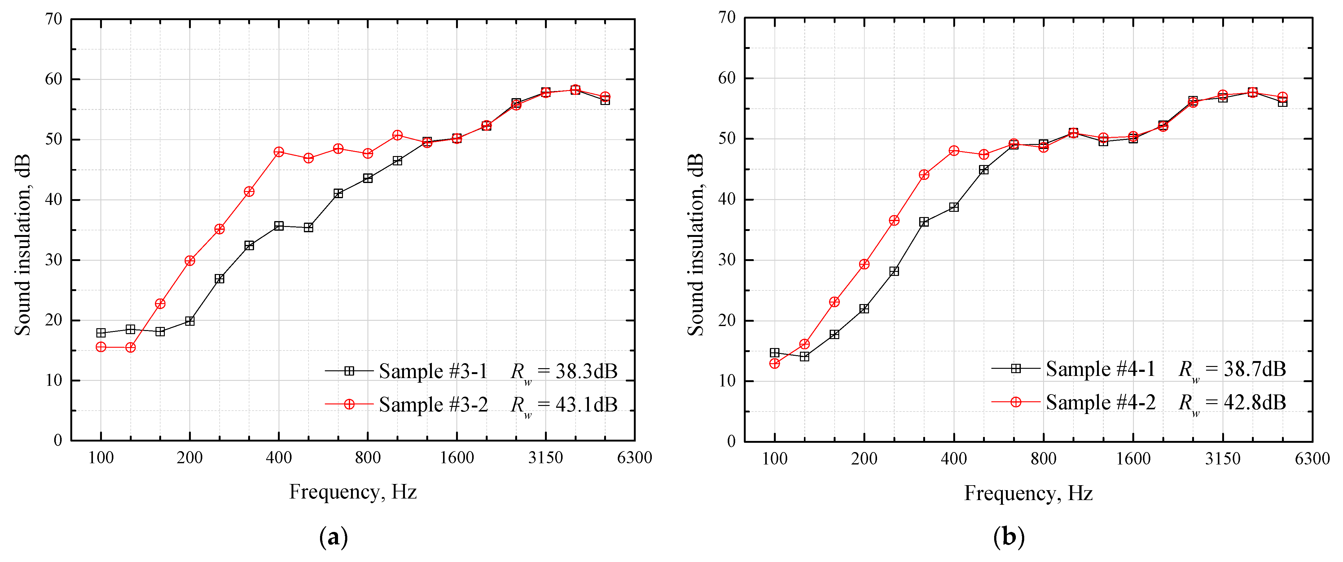
- For a simple sandwich composite structure, the core layer material laying strategy of “laying sound-absorbing materials in the middle and sound-insulation materials on both sides” has a better effect on sound insulation for low and medium frequencies, and the increase is even more than 10 dB around 400 Hz, compared with “alternating laying of sound-absorbing materials and sound-insulation materials”. Furthermore, for the overall weighted sound reduction index Rw, it can be increased by more than 4 dB.
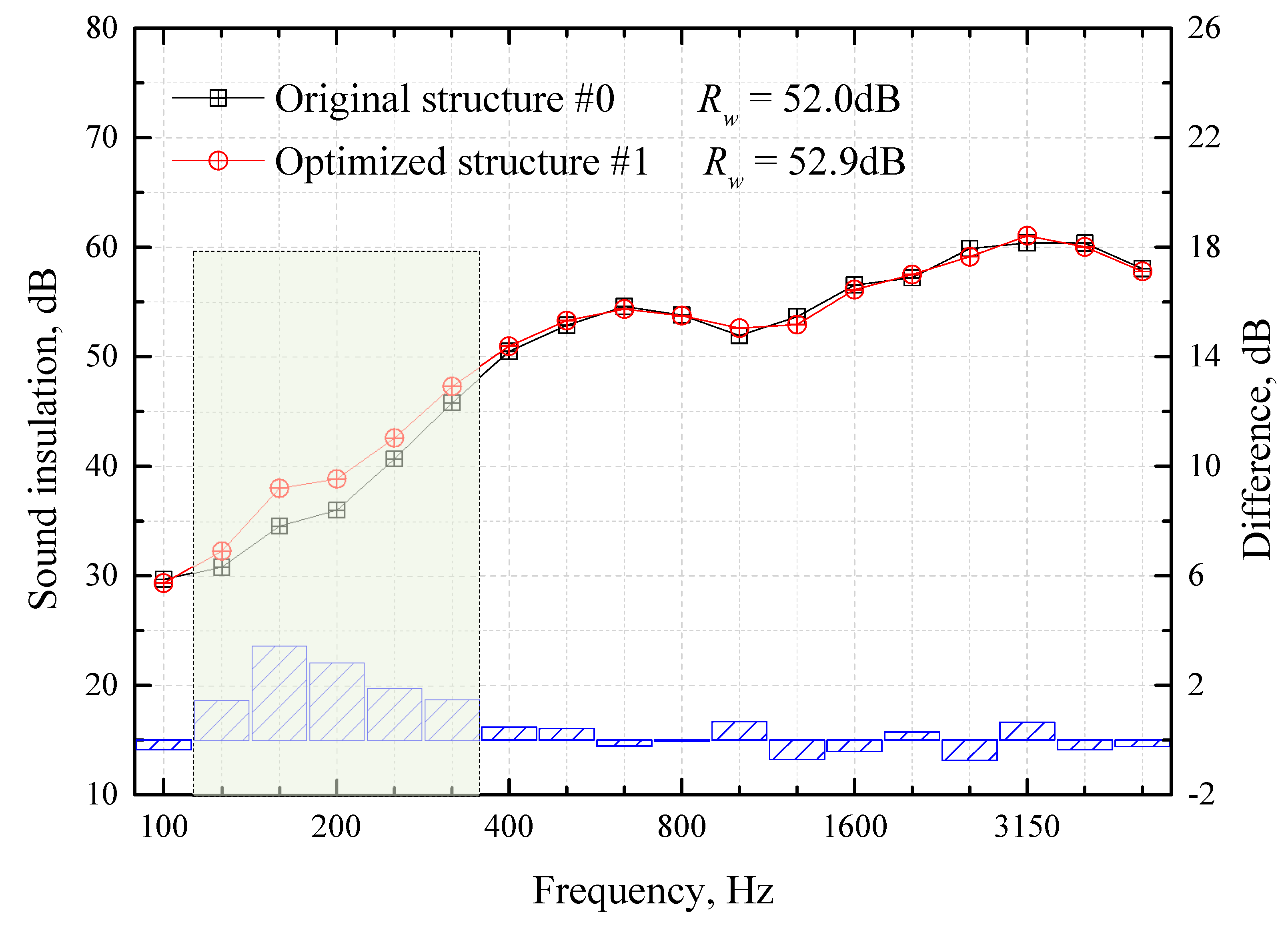
- The core layer material laying strategy of “laying sound-absorbing materials in the middle and sound-insulation materials on both sides” is applied to the sound-insulation design of the high-speed train carbody. Under the premise of not changing the type, thickness and weight of materials, the low and medium frequency sound insulations of 125–315 Hz are improved by 1–3 dB, and the overall weighted sound reduction index Rw is improved by 0.9 dB.
- By changing the laying sequence of the core layer materials, the sound-insulation performance of the composite structure can be improved without any change to the space, thickness, weight and material type of the structure. It is easy to implement, is low cost and has high engineering practical value.
Author Contributions
Funding
Institutional Review Board Statement
Informed Consent Statement
Data Availability Statement
Conflicts of Interest
References
- Song, S.; Lin, P.; Zhao, Y.-J.; Chen, H.-W. Prediction of sound transmission loss of composite floor structures of high speed trains. In Proceedings of the INTER-NOISE 2017-46th International Congress and Exposition on Noise Control Engineering: Taming Noise and Moving Quiet, Hong Kong, China, 27–30 August 2017. [Google Scholar]
- Deng, T.-S.; Sheng, X.-Z.; Jeong, H.; Thompson, D.J. A two-and-half dimensional finite element/boundary element model for predicting the vibro-acoustic behaviour of panels with poro-elastic media. J. Sound Vib. 2021, 505, 116147. [Google Scholar] [CrossRef]
- Zhang, J.; Yao, D.; Wang, R.-Q.; Xiao, X.-B. Vibro-acoustic modelling of high-speed train composite floor and contribution analysis of its constituent materials. Compos. Struct. 2021, 256, 113049. [Google Scholar] [CrossRef]
- Yao, D.; Zhang, J.; Wang, R.-Q.; Xiao, X.-B.; Guo, J.-Q. Lightweight design and sound insulation characteristic optimisation of railway floating floor structures. Appl. Acoust. 2019, 156, 66–77. [Google Scholar] [CrossRef]
- Yao, D.; Zhang, J.; Wang, R.-Q.; Xiao, X.-B. Vibroacoustic damping optimisation of high-speed train floor panels in low- and mid-frequency range. Appl. Acoust. 2020, 174, 107788. [Google Scholar] [CrossRef]
- Lin, L.-Z.; Ding, Z.-Y.; Zeng, J.-K.; Zhang, C.-X. Research on the transmission loss of the floor aluminum profile for the high-speed train based on FE-SEA hybrid method. J. Vibroeng. 2016, 18, 1968–1981. [Google Scholar] [CrossRef]
- Zhang, Y.-M.; Thompson, D.; Squicciarini, G.; Ryue, J.; Xiao, X.-B.; Wen, Z.-F. Sound transmission loss properties of truss core extruded panels. Appl. Acoust. 2018, 131, 134–153. [Google Scholar] [CrossRef]
- Nurzyński, J.; Nowotny, Ł. Acoustic performance of floors made of composite panels. Materials 2023, 16, 2128. [Google Scholar] [CrossRef] [PubMed]
- Li, S.; Xu, D.; Wu, X.; Jiang, R.; Shi, G.; Zhang, Z. Sound insulation performance of composite double sandwich panels with periodic arrays of shunted piezoelectric patches. Materials 2022, 15, 490. [Google Scholar] [CrossRef] [PubMed]
- Hu, Q.-L.; Bian, G.-F.; Qiu, Y.-P.; Wei, Y.; Xu, Z.-Z. Sound insulation properties of honeycomb sandwich structure composite for high-speed train floors. J. Text. Res. 2001, 42, 75–83. [Google Scholar]
- Seockhyun, K.; Taegun, S. Sound insulation performance of honeycomb composite panel for a tilting train. Trans. Korean Soc. Mech. Eng. A 2010, 34, 1931–1936. [Google Scholar]
- Kim, S.H.; Seo, T.G.; Kim, J.T.; Song, D.H. Sound-insulation design of aluminum extruded panel in next-generation high-speed train. Trans. Korean Soc. Mech. Eng. A 2011, 35, 567–574. [Google Scholar] [CrossRef]
- Kaidouchi, H.; Kebdani, S.; Slimane, S.A. Vibro-acoustic analysis of the sound transmission through aerospace composite structures. Mech. Adv. Mater. Struct. 2022, 3, 1–11. [Google Scholar] [CrossRef]
- Kang, L.; Sun, C.; An, F.; Liu, B. A bending stiffness criterion for sandwich panels with high sound insulation and its realization through low specific modulus layers. J. Sound Vib. 2022, 536, 117149. [Google Scholar] [CrossRef]
- Liu, X.-B.; Yang, Y.; Le, V. Airborne sound insulation of aluminum extrusion structural walls of an urban rail train. Noise Control Eng. J. 2014, 62, 47–53. [Google Scholar] [CrossRef]
- Zhang, J.; Yao, D.; Wang, P.; Wang, R.-Q.; Li, J.; Guo, S.-Y. Optimal design of lightweight acoustic metamaterials for low-frequency noise and vibration control of high-speed train composite floor. Appl. Acoust. 2022, 199, 109041. [Google Scholar] [CrossRef]
- Lyon, R.H.; DeJong, R.G.; Heckl, M. Theory and Application of Statistical Energy Analysis, 2nd ed.; Butterworth-Heinemann: Boston, MA, USA, 1995. [Google Scholar]
- Oliazadeh, P.; Farshidianfar, A.; Crocker, M.J. Experimental study and analytical modeling of sound transmission through honeycomb sandwich panels using SEA method. Compos. Struct. 2022, 280, 114927. [Google Scholar] [CrossRef]
- Huang, X.-F.; Lu, Y.-M.; Qu, C.; Zhu, C.-H. Study on Sound Transmission across a Floating Floor in a Residential Building by Using SEA. Arch. Acoust. J. Pol. Acad. Sci. 2021, 46, 183–194. [Google Scholar]
- Hyoseon, J.; Carl, H. Prediction of sound transmission in long spaces using ray tracing and experimental Statistical Energy Analysis. Appl. Acoust. 2018, 130, 15–33. [Google Scholar] [CrossRef]
- VA One 2012 User’s Guide; The ESI Group: Rungis, France, 2012.
- Su, J.-T.; Zheng, L.; Lou, J.-P. Simulation and Optimization of Acoustic Package of Dash Panel Based on SEA. Shock Vib. 2020, 2020, 8855280. [Google Scholar] [CrossRef]
- Hossein, S.; Abolfazl, K.; Amin, M. A practical procedure for vehicle sound package design using statistical energy analysis. Proc. Inst. Mech. Eng. Part D J. Automob. Eng. 2022, 1–16. [Google Scholar] [CrossRef]
- Zhang, X.-X.; Wu, X.-R.; Cheng, Y.-H.; Jin, H.-Y.; Zhang, J. Application Research of Statistical Energy Analysis on Vehicle Sound Package. In FISITA World Automotive Congress; Springer: Berlin/Heidelberg, Germany, 2012; pp. 507–520. [Google Scholar] [CrossRef]
- ISO 717–1:2013; Acoustics—Rating of Sound Insulation in Buildings and of Building Elements—Part 1: Airborne Sound Insulation. International Organization for Standardization: Geneva, Switzerland, 2013.
- ISO 10140-2:2021; Acoustics—Laboratory Measurement of Sound Insulation of Building Elements—Part 2: Measurement of Airborne Sound Insulation. International Organization for Standardization: Geneva, Switzerland, 2021.


| Parameters | Aluminum Plate | Plywood | Hard Rubber | Light Glass Wool |
|---|---|---|---|---|
| Density (kg/m3) | 2700 | 700 | 1100 | 16 |
| Elasticity modulus (GPa) | 71.0 | 6.0 | 2.3 | \ |
| Poisson’s ratio | 0.33 | 0.25 | 0.49 | \ |
| Porosity | \ | \ | \ | 0.99 |
| Flow resistivity (N.s/m4) | \ | \ | \ | 9000 |
| No. | Sample #1-1 | Sample #1-2 | Sample #1-3 | Sample #1-4 |
|---|---|---|---|---|
| Core layer material composition | 10 mm light glass wool | 4 mm hard rubber | 15 mm light glass wool | 2 mm hard rubber |
| 2 mm hard rubber | 30 mm light glass wool | |||
| 10 mm light glass wool | 30 mm light glass wool | 4 mm hard rubber | ||
| 2 mm hard rubber | 15 mm light glass wool | |||
| 10 mm light glass wool | 2 mm hard rubber |
| No. | Sample #2-1 | Sample #2-2 | Sample #2-3 | Sample #2-4 |
|---|---|---|---|---|
| Core layer material composition | 20 mm light glass wool | 2 mm hard rubber | 30 mm light glass wool | 1 mm hard rubber |
| 1 mm hard rubber | 60 mm light glass wool | |||
| 20 mm light glass wool | 60 mm light glass wool | 2 mm hard rubber | ||
| 1 mm hard rubber | 30 mm light glass wool | |||
| 20 mm light glass wool | 1 mm hard rubber |
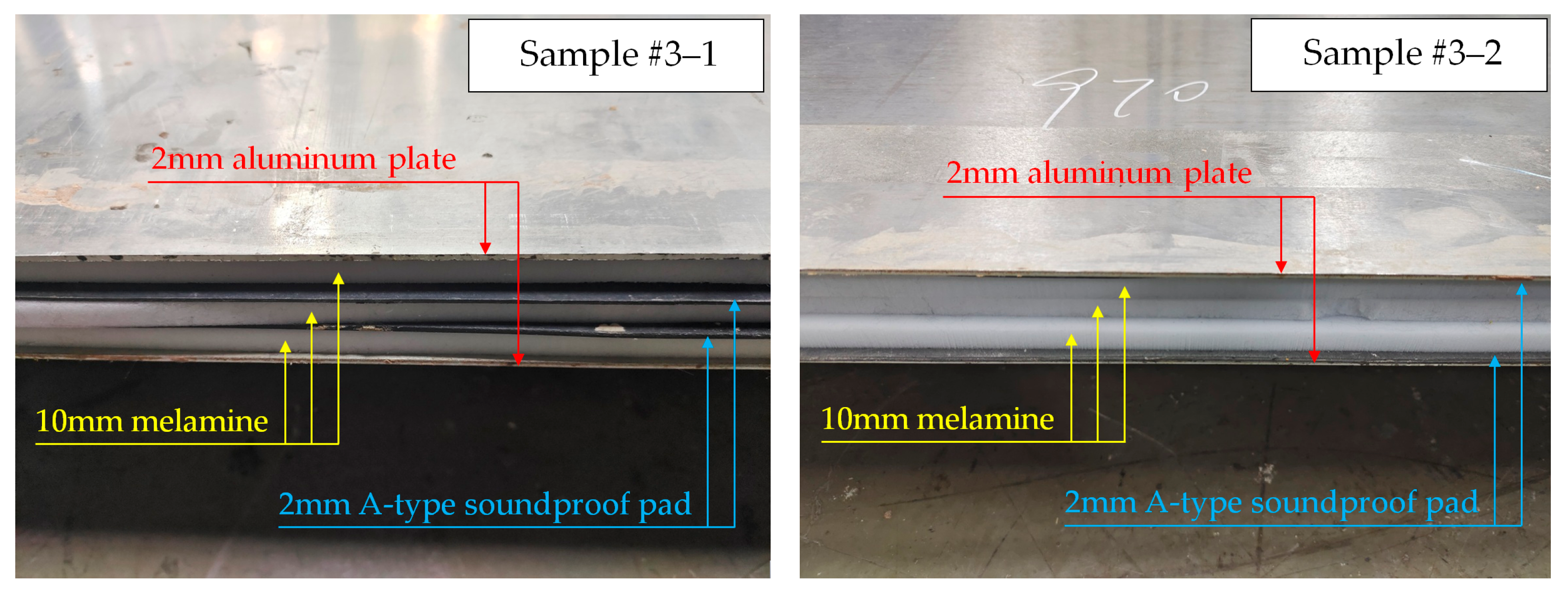
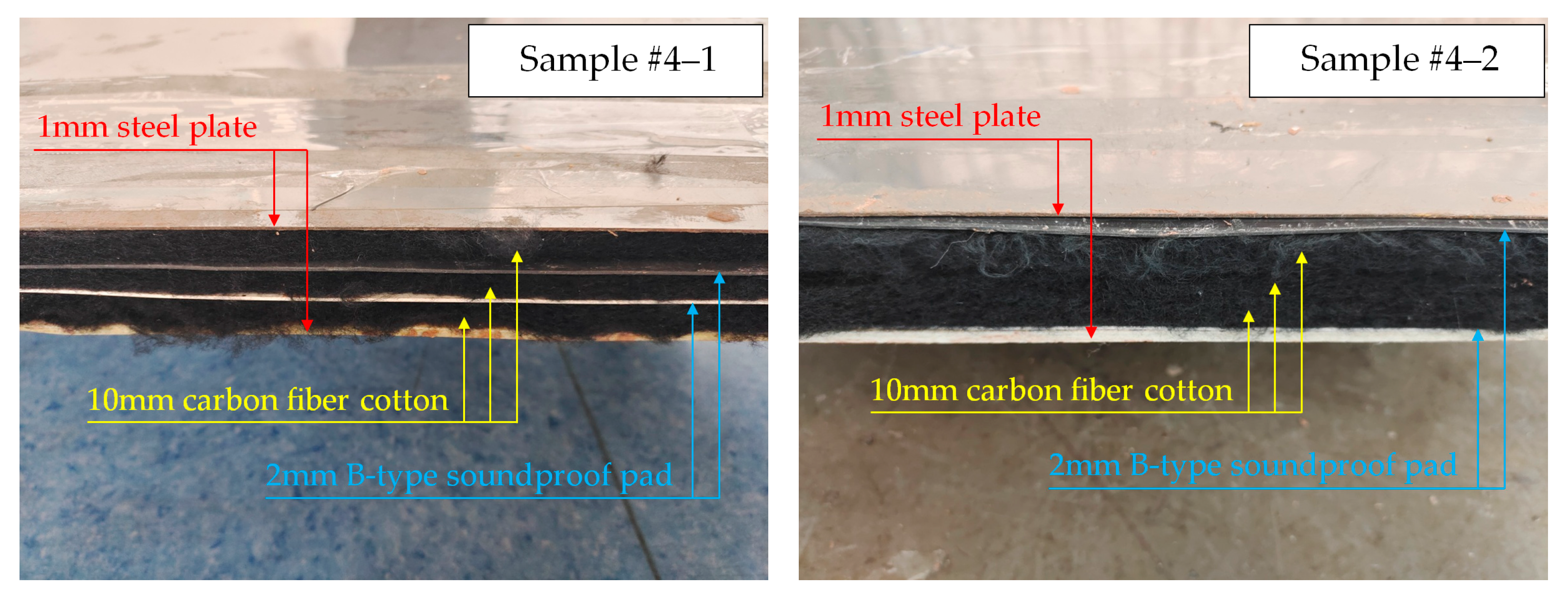
| No. | Group #3 | Group #4 | ||
|---|---|---|---|---|
| Sample #3-1 | Sample #3-2 | Sample #4-1 | Sample #4-2 | |
| Core layer material composition | 10 mm melamine | 2 mm A-type soundproof pad | 10 mm carbon fiber cotton | 2 mm B-type soundproof pad |
| 2 mm A-type soundproof pad | 10 mm melamine | 1 mm B-type soundproof pad | 10 mm carbon fiber cotton | |
| 10 mm melamine | 10 mm melamine | 10 mm carbon fiber cotton | 10 mm carbon fiber cotton | |
| 2 mm A-type soundproof pad | 10 mm melamine | 1 mm B-type soundproof pad | 10 mm carbon fiber cotton | |
| 10 mm melamine | 2 mm A-type soundproof pad | 10 mm carbon fiber cotton | 2 mm B-type soundproof pad | |
| No. | Original Structure #0 | Optimized Structure #1 |
|---|---|---|
| Core layer material composition | 5 mm soundproof pad #1 | 5 mm soundproof pad #1 |
| 10 mm sound-absorbing material #1 | 10 mm sound-absorbing material #1 | |
| 3 mm soundproof pad #2 | 20 mm sound-absorbing material #2 | |
| 20 mm sound-absorbing material #2 | 15 mm sound-absorbing material #3 | |
| 2 mm soundproof pad #3 | 3 mm soundproof pad #2 | |
| 15 mm sound-absorbing material #3 | 2 mm soundproof pad #3 | |
| Weight (kg) | 24.6 | 24.6 |
| Thickness (mm) | 55.0 | 55.0 |
Disclaimer/Publisher’s Note: The statements, opinions and data contained in all publications are solely those of the individual author(s) and contributor(s) and not of MDPI and/or the editor(s). MDPI and/or the editor(s) disclaim responsibility for any injury to people or property resulting from any ideas, methods, instructions or products referred to in the content. |
© 2023 by the authors. Licensee MDPI, Basel, Switzerland. This article is an open access article distributed under the terms and conditions of the Creative Commons Attribution (CC BY) license (https://creativecommons.org/licenses/by/4.0/).
Share and Cite
Wang, R.; Yao, D.; Zhang, J.; Xiao, X.; Jin, X. Effect of the Laying Order of Core Layer Materials on the Sound-Insulation Performance of High-Speed Train Carbody. Materials 2023, 16, 3862. https://doi.org/10.3390/ma16103862
Wang R, Yao D, Zhang J, Xiao X, Jin X. Effect of the Laying Order of Core Layer Materials on the Sound-Insulation Performance of High-Speed Train Carbody. Materials. 2023; 16(10):3862. https://doi.org/10.3390/ma16103862
Chicago/Turabian StyleWang, Ruiqian, Dan Yao, Jie Zhang, Xinbiao Xiao, and Xuesong Jin. 2023. "Effect of the Laying Order of Core Layer Materials on the Sound-Insulation Performance of High-Speed Train Carbody" Materials 16, no. 10: 3862. https://doi.org/10.3390/ma16103862
APA StyleWang, R., Yao, D., Zhang, J., Xiao, X., & Jin, X. (2023). Effect of the Laying Order of Core Layer Materials on the Sound-Insulation Performance of High-Speed Train Carbody. Materials, 16(10), 3862. https://doi.org/10.3390/ma16103862