1. Introduction
The challenges arising from the sustainable development policy [
1], primarily concerning the reduction of CO
2 emissions, are related to a large extent to the automotive industry. This in turn is associated with energy saving and the effective use of natural resources. Actions taken in this area should have a direct impact on reducing exhaust emissions of vehicles powered by traditional drive systems, as well as stimulate the rapid development of electric vehicles [
2]. For this reason, efforts have been made to reduce the weight of passenger car bodies, while meeting all the required safety standards [
3]. Therefore, the production of parts of load-bearing structures of modern car bodies forces the use of new construction materials and new technologies for their production.
The dominant technology for manufacturing parts for the needs of the automotive industry is the stamping process [
4,
5]. In commonly used cold stamping processes, the production of ultralight components included in load-bearing structures of a car body is possible thanks to the use of DP (
Dual Phase steels) with a tensile strength of up to 1000–1200 MPa [
6,
7]. Owing to such good strength parameters, while maintaining appropriate formability, it is possible to make sheet metal drawpieces of reduced thickness, without damaging the mechanical properties of a ready drawpiece. The cold pressing process takes place at a temperature close to the ambient temperature. The material in the form of sheet metal, wound on a coil is fed from the decoiler through the conveyer to the straightening device (
Figure 1). Next, after passing through a series of straightening rollers, the material is collected in a loop pit. In the next stage, the sheet is transported to the press with a stamping die mounted on its table. After undergoing subsequent trimming and forming operations, the drawpiece is ready. Depending on the complexity of the product, the dies are made as progressive or transfer dies. In the first case, during the entire technological manufacturing process, a drawpiece is connected to the steel belt. In transfer dies, the product is moved between operations with the use of special grippers. It should be clearly emphasized that the quality of the drawpiece in the cold pressing process (shape and dimensional accuracy) is primarily influenced by the perfection of the die design. Strength properties of the finished product result from the properties of the material that is to be used for production. At this point, it is worth mentioning the unfavourable phenomenon of return springing of drawpieces which is particularly difficult to control during the production of DP steel components. This is one of the reasons for the increasing use of hot stamping technology.
For over a dozen years, more and more body elements of new car models have been produced from manganese-boron steels [
8,
9,
10,
11,
12] in the hot stamping technology [
13]. After the hot stamping process, the material can achieve a tensile strength of up to 1900 MPa [
14], which is a completely new quality in the production of high-strength drawpieces. In addition, this technology allows the production of drawpieces with areas of different thicknesses and, thus, with different mechanical properties in these areas [
15,
16]. In the process of cold pressing, obtaining such an effect is extremely difficult. During hot stamping, the drawpiece is shaped and quenched at the same time. The material changes from a ferritic–pearlitic structure to a martensitic structure. In order to achieve this result, a high cooling rate of at least 27 K/s is required. This forces the production of a tool with a special design with appropriately selected cooling channels [
17,
18,
19]. The process itself is much more complicated than the cold pressing process, both in terms of the organization of the production line and the production technology of the drawpiece. For this reason, when preparing production with this technology, a digital twin [
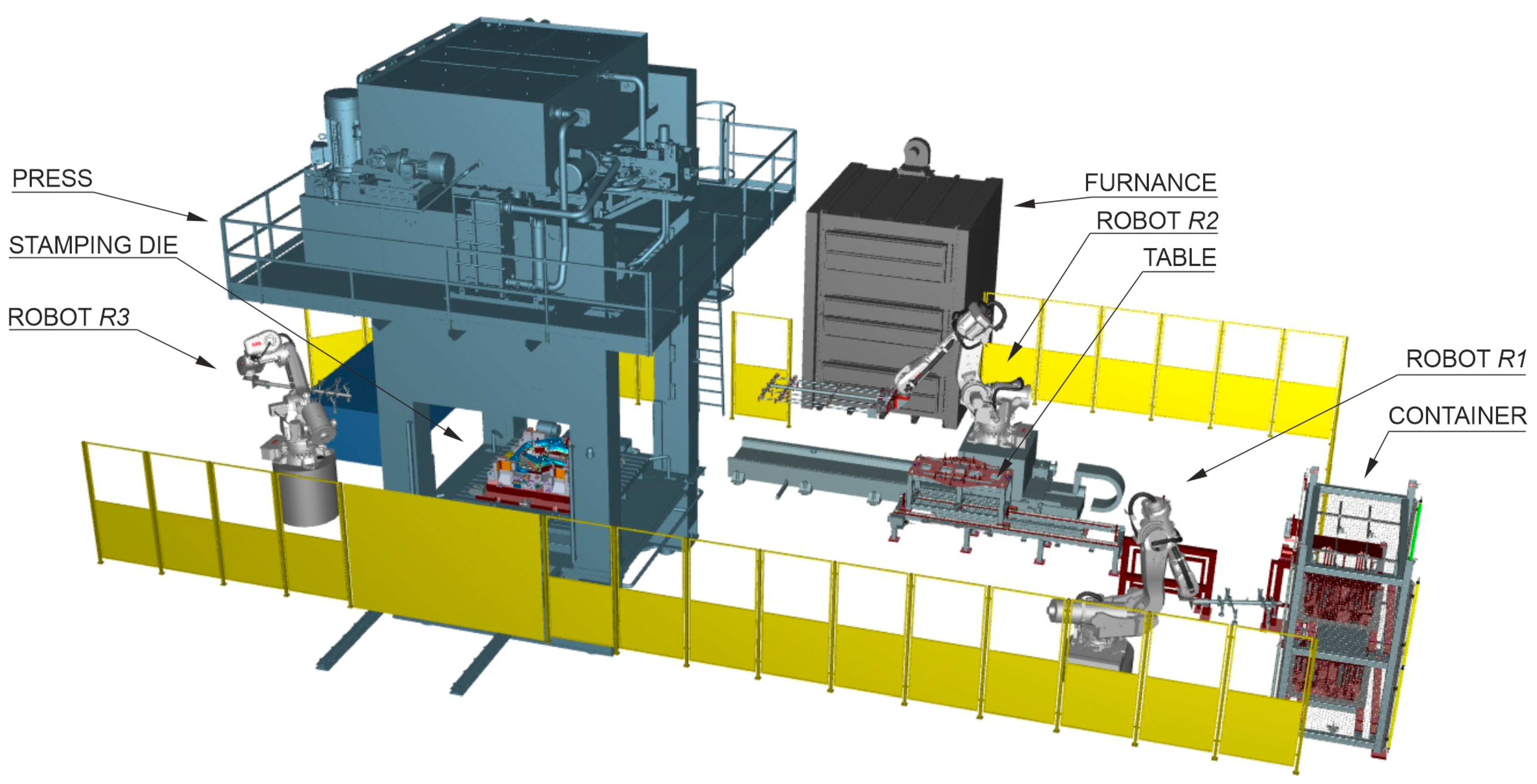
20] of the production line (
Figure 2) is built in accordance with the assumptions of Industry 4.0 [
21,
22]. The twin is used to analyse the entire process of producing drawpieces.
During this process, properly prepared blanks are taken from a special container by the R1 robot’s arm and fed to the table, from which the R2 robot transfers them to the furnace. There, the blank is heated to the temperature of about 900–930 °C (austenitisation temperature), required for the proper drawpiece quenching. Next, the same robot transfers the heated blank from the furnace to the stamping die, and the forming stage begins. The tools are closed, and the pressing force of the press is significantly increased to the acceptable value in order to improve the conditions of heat exchange between the product and the working surfaces of the tools. The quenching process begins. In the next stage, the finished product is collected from the die by the R3 robot arm. Depending on the organization of the production line, the drawpiece is placed in a container or transferred directly to the control and measurement station by a belt conveyor. All activities must be properly synchronized, and production should take place in the shortest time possible. This is a big challenge for designers of such a process.
The quality of the drawpiece obtained in the hot stamping process should be understood not only as maintaining appropriate shape and dimensional accuracy but also as achieving appropriate mechanical properties of the product in the process of stamping and quenching. The final properties of the finished drawpiece are influenced by many more factors than in the case of cold stamping. These factors include the temperature and time of heating the blanks in the furnace, the time of transferring the blanks to the die, the temperature at the beginning of the stamping process, the quenching time, and the final temperature of the drawpiece.
The main task of the systems for monitoring and diagnosing stamping processes is to ensure the correct and stable course of the manufacturing process, which will allow the production of drawpieces of repeatable quality. Monitoring cold pressing is primarily about preventing critical situations that lead to die damage. Inductive sensors are installed in progressive dies. Their task is to control if the sheet metal strip is moved by the appropriate stroke value in each press cycle. In transfer dies, optical sensors are used to check whether the drawpiece is transferred by grippers to the next operation. If, in the transfer process, the drawpiece is made of a pre-punched sheet of metal, thickness control is additionally performed to prevent accidentally glued sheets of metal from being fed into the die. In addition, in special cases, laser sensors are used to check whether the waste generated in the cutting process is properly discharged. If additional operations are performed in the stamping process, e.g., threading operations, pressure sensors check if the tap is not broken. This also applies to punches that punch holes of small diameters.
Monitoring key process parameters during hot stamping is a completely different issue. Here, as noted earlier, the quality of the final product is influenced by many more factors that must be constantly controlled. The first group of process control systems (
Figure 3) consists of measurement systems cooperating with the automation of the production line. They control the process parameters in real time, and based on the measured values, an adequate response of individual machines operating on the line is taken. This group includes the blank thickness sensor, temperature sensors in the furnace chambers, dew point sensors of the furnace atmosphere, sensors of the blank position in the tool, temperature sensors of the working surfaces of the tool, temperature sensors of the blank after being removed from the furnace, and temperature sensors of cooling water at the inlet and outlet of the stamping die. The second group of measurement systems includes systems for controlling the quality of drawpieces. Optical measurement of the shape-dimensional accuracy of the produced drawpiece and measurement of the mechanical properties of drawpieces using non-destructive testing devices are performed here.
The vast majority of publications dealing with issues of stamping process control refer to monitoring selected parameters during the cold forming process. Some attention is given to the measurement of stamping forces. The results of these measurements are often treated as a reference point for the validation of numerical simulations, or they are used to control the uniformity of pressure loads in the die, as described in [
23]. Monitoring pressure loads and the deep drawing process with the use of a system of sensors integrated with the tool is described in [
24]. In [
25], an attempt was made to monitor stamping processes using acceleration sensors with a bi-spectral analysis of the measurement results. Due to the ease of obtaining such a signal and the low cost of installing the sensor, this method was considered promising. The use of machine learning techniques to control the stamping process is presented in, among others, [
26,
27]. The method of detecting defects in drawpieces using vision systems is presented in, among others, [
28].
Very few publications address this topic in relation to hot stamping processes. An extensive study [
29] presents an overview of issues related to the construction and operation of modern stamping dies. These are of general nature and concern many aspects, e.g., materials used for the construction of tools, methods of working surface treatment, assessment of tool durability, and methods of their regeneration. In particular, part of the work was devoted to monitoring systems for stamping processes, including hot stamping, and their control based on the collected measurement data. The concept of a real-time monitoring system for hot stamping process parameters is presented in [
30]. The system is designed to collect and process data from sensors installed on individual line elements. These data are stored in the database and are the basis for further analysis, thanks to which it is possible to forecast possible faults or failures. Article [
31] presents a method of solving the problems related to the temperature control of the blank heated in the furnace to about 800–900 °C and the drawpiece at the temperature of 100–200 °C. The temperature was measured using a thermal imaging camera. A special algorithm was proposed that solves the problem of different settings of the thermal imaging camera for measuring temperatures with a large difference. Work [
32] presents a system for monitoring acoustic emission in the hot stamping process. This system is designed to track the condition of the die and punch and detect the beginnings of their wear.
The main goal of the work is to prepare a control system for an experimental hot stamping line intended for the production of drawpieces in PHS (Press Hardened Steels) technology. As part of the conducted studies, the most important technological parameters affecting the process and the method of measuring these values with the use of appropriate sensors and measurement systems were selected. Acceptable limits of their variability and the method of system reaction (production line control algorithm) to any deviations from the set values were determined. Initial values of production parameters were chosen via performing a series of simulations of the stamping process using the Finite Element Method as well as the knowledge and experience of engineers and specialists in hot forming. The layout of the line, from the moment of taking the blank from the warehouse to the moment of transferring the finished drawpiece for measurement, was designed using digital twins of the process. The correctness of the line operation was assessed on the basis of tests of a trial series of drawpieces. These tests include testing mechanical properties such as hardness—HV (Vickers scale), yield strength—Rp0.2 and strength limit—Rm, as well as measurements of shape and dimensional accuracy. In addition, microstructure tests and long-term measurements of hydrogen embrittlement of the drawpieces will be performed in a four-point bending test. The novelty of this study is a comprehensive approach to the hot stamping process control. It includes the selection of initial values of technological parameters by simulation of the stamping process, determination of the method of measuring these parameters on the real production line, as well as detailed quality control of the produced drawpieces.
2. Measuring Systems Used for Controlling Hot Forming Process
This section will discuss the measurements that monitor the pressing process itself. In some cases, especially for those less common in industrial practice, the principle of their operation will be presented; in the case of dew point measurement, the motivation for this measurement will also be presented. In other cases, their role in the process will be indicated.
2.1. Measurement of the Blank Thickness
During the operation of the automatic hot stamping line, pre-prepared flat pieces are taken from the warehouse. The first sensor mounted on the line is the thickness sensor. It measures the thickness of the sheet, preventing two blanks glued together from entering the production process. Such a situation is unacceptable. Potential placement of more than one form in the die may, at best, damage the working surfaces of the dies and punches or lead to the destruction of the tool. Two types of sheet thickness sensors are used on hot stamping lines: ultrasonic sensors and optical sensors. The former, commonly used in many fields for several decades, operate based on measuring the speed of ultrasonic wave propagation in the tested material. The scope of their application is very wide, ranging from measuring the thickness of various materials, including multi-layer materials, through measuring the thickness of varnished coatings to detecting damage or discontinuities caused by, e.g., corrosion pitting in places inaccessible for other methods.
Currently, modern optical sensors are used much more frequently. They perform measurements based on the principle of optical triangulation. A laser diode (class 2 laser) illuminates a point on the surface to be measured. The light reflected from this point is directed to a photosensitive matrix, where it is processed into a distance dimension. Most often, sheet thickness measurement is carried out using the differential measurement method (
Figure 4). It consists of coupling two synchronously operating sensors and subtracting the values measured by these sensors from the fixed distance between them. Thanks to this solution, when the measured object moves within the measuring field, the measured value does not change.
The signal from this sensor affects the way the
R1 robot works (
Figure 2). If the sensor indicates too much thickness of the blank, the blank is put back into the container. Otherwise, it goes to the table operated by
R2 robot and is loaded into the furnace.
2.2. Measurement of Temperature in the Furnace
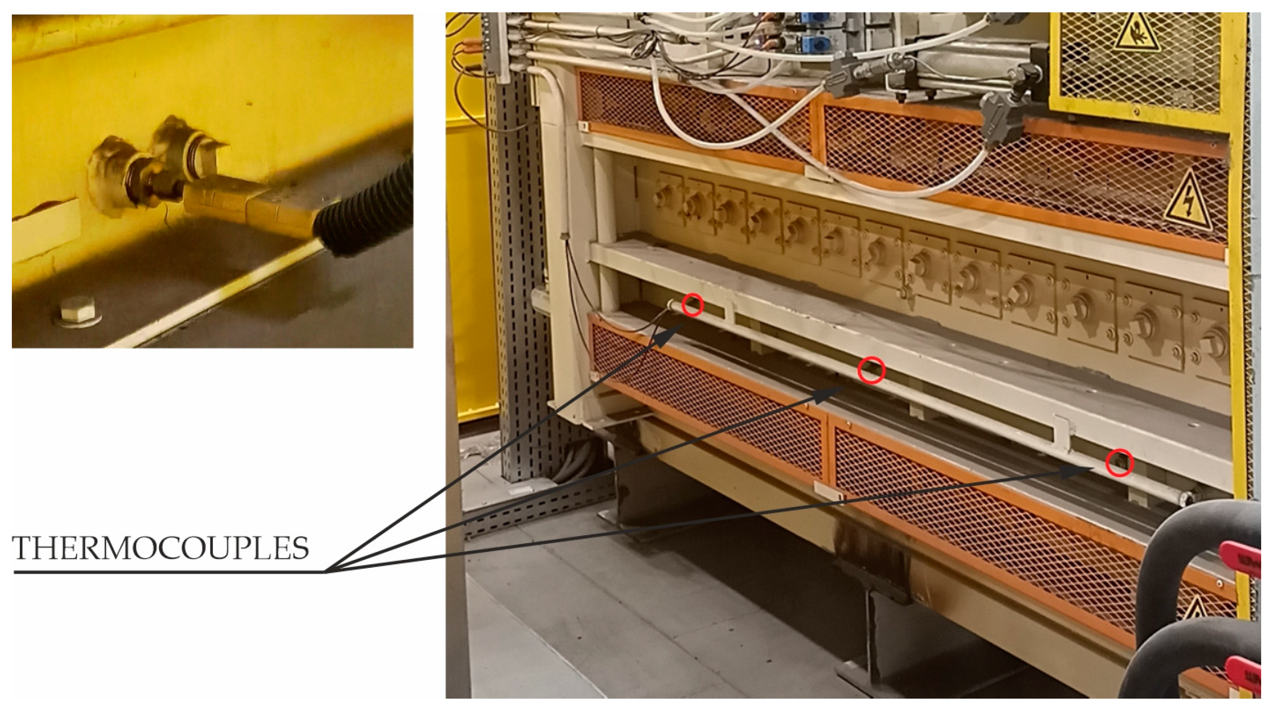
Thermocouples installed in each of the three chambers of the furnace are used to control the temperature of the furnace in which the forms are heated to the austenitising temperature.
The values obtained from the thermocouples are used to control the operation of the heaters responsible for maintaining the required temperature in the chamber. This is usually a two-stage control with fixed temperature thresholds. When the measured temperature in the chamber drops below 890 °C, the heaters are switched on and heat the furnace chamber. When the temperature exceeds 930 °C, the power of the heaters is turned off.
Figure 5 shows the location of the thermocouples installed in one of the furnace chambers in the discussed hot stamping line.
If it is not possible to maintain the temperatures in the furnace within the required range of 890–930 °C, the process is stopped. This indicates a failure of the furnace.
2.3. Measurement of Dew Point Temperature of Furnace Atmosphere
When the blanks are heated, an undesirable phenomenon of hydrogen diffusion to the structure of steel used in hot stamping processes (22MnB5) may occur. This may lead to the formation of the so-called hydrogen embrittlement of drawpieces [
33,
34,
35]. As a result of increasing the hydrogen content in the finished drawpieces, local stresses may arise, causing the loss of structural cohesion. The effects of hydrogen are long-lasting. Undesirable cracks in the drawpieces may occur shortly after production, during the assembly of the bodywork, as well as during the operation of the car. Manufacturers of modern vehicles built from elements produced in the PHS technology recognise this problem and expect that the causes of hydrogen embrittlement will be eliminated already at the production stage. This is related to limiting the amount of hydrogen diffusing into the material during the heating of the blanks.
After opening the furnace door in order to take a heated blank or load a blank for heating, the air from the furnace mixes with the ambient air. To reduce the amount of water vapour in the furnace atmosphere, dried air is blown into the chamber. It is estimated that in order to significantly reduce the risk of hydrogen embrittlement of the manufactured products, it is necessary to maintain an air atmosphere in the furnace with a degree of humidity of about 0.0025 kg H2O/kg of dry air. This corresponds to the partial pressure of water vapour of about 400 Pa (dew point equal to −5 °C). Such a requirement is included in the standards of car manufacturers for the quality of drawpieces.
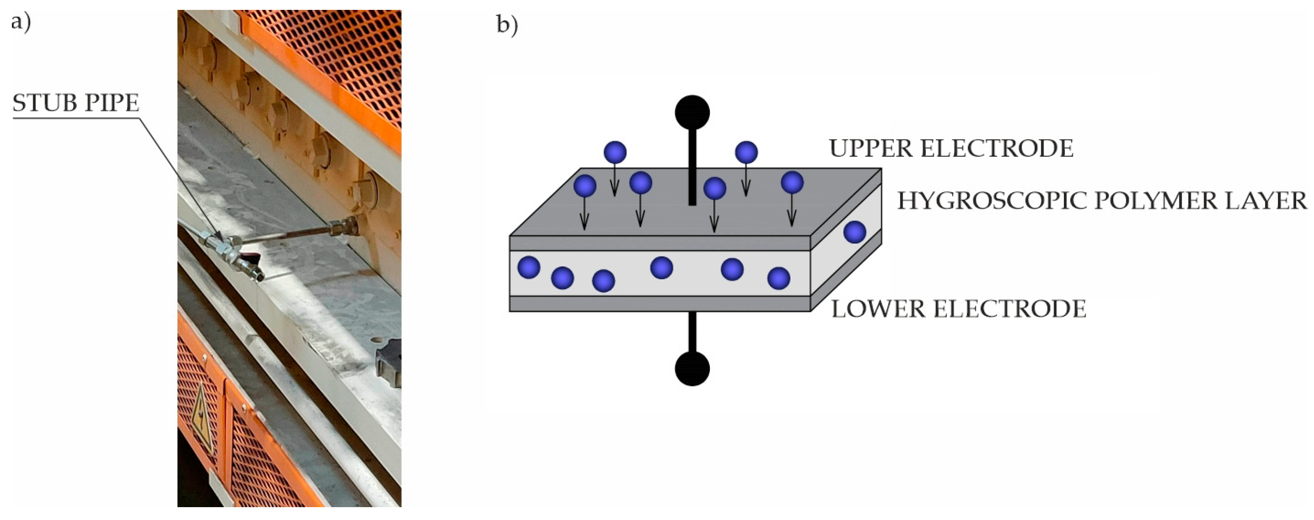
The dew point temperature is measured for the air taken from the furnace using a special stub pipe (
Figure 6a), from where it goes to the capacitive humidity sensor (
Figure 6b).
Such a sensor is equipped with two electrodes separated from each other by a thin layer of hygroscopic polymer acting as a dielectric. The change in the dielectric constant of the hygroscopic material is proportional to the measured relative humidity of the air. By additionally measuring the air temperature, the dew point temperature is determined. If its value is greater than the admissible value, the flow of dried air to the furnace chamber is increased.
2.4. Measurement of the Blank Temperature
The first measurement performed before the stamping process starts is the measurement of the temperature of the blank. For this purpose, a pyrometer mounted on the body of the press is used (
Figure 7). When the measured temperature of the blank is lower than 780 °C, which may result in incorrect quenching process, the automation controlling the hot stamping line sends information to
R2 robot (
Figure 2) responsible for transferring the heated blank from the furnace to the die to put the blank to a scrap container. Drawpiece buyers, such as large car concerns, do not allow the possibility of reusing such material. Al-Si coatings, which cover blanks after reheating, grow excessively. This causes, among other things, problems when spot-welding of drawpieces. The details are discussed in [
36,
37].
2.5. Measurement of Positioning of the Blank on the Stamping Die
After placing the blank on the die, the thermal imaging camera verifies the accuracy of its positioning. The robot transfers the blank from the furnace to the die and puts it down when the base hole of the blank is above the tool’s base pin. This ensures proper placement of the blank before the forming process begins. There is a risk of placing the blank on the tool incorrectly, for example by improperly picking up the blank from the furnace. This situation can lead to permanent and costly damage to the tool components. In order to prevent such situations, control systems, which analyse the image from the thermal imaging camera, are used. When the camera receives a signal from the control system about placing the form on the die, it takes a picture (in this case, a monochrome one). The system, based on the previously defined eight measuring points (
Figure 8), measures the shortest distance between these points and the detected edges of the blank. When the calculated distance values are within the set tolerances, the line control system allows the press punch to move down, and the stamping process begins. Otherwise, the line is stopped, and a piece position error signal appears. The blank is manually removed from the die, and the production process is restarted.
2.6. Temperature Measurements of the Tools after the Stamping Process
In the stamping process, it is very important to control the temperature of the die and punch after removing the drawpiece from the tool. A thermovision camera and a set of pyrometers are used to measure the temperature of the tools after the stamping process (
Figure 9).
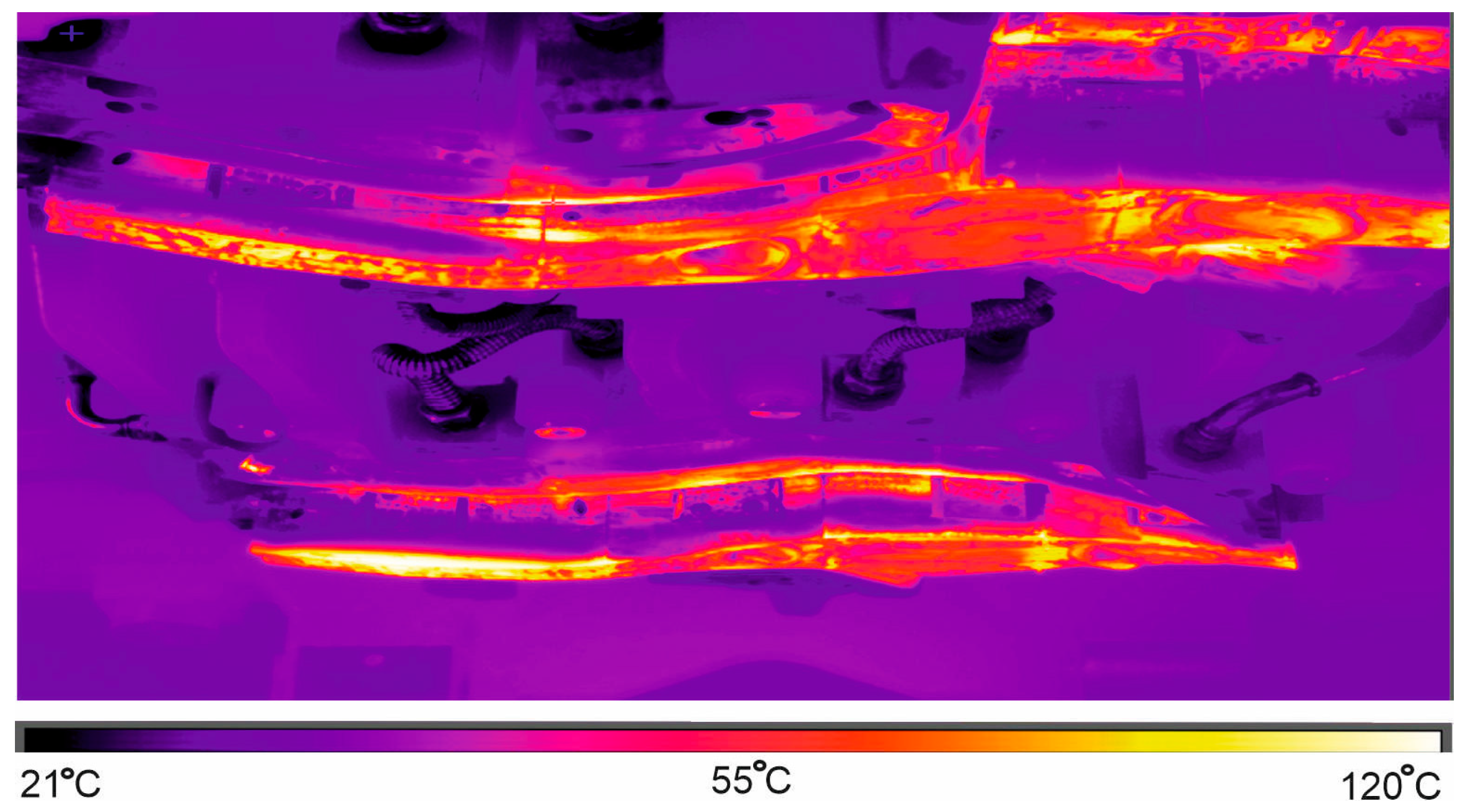
After removing the finished drawpiece from the die, the system controlling the automated production line sends the signal to thermal imaging camera, which measures temperature of working surfaces of the die and the punch. After the pressing process, these temperature values should not exceed 200 °C. In addition, in some cases, pyrometers are used to measure temperature in these places of the die where overheating points (so-called hot spots) were identified at the development stage of the hot stamping process and at the stage of its computer simulation. There the temperature can be up to 250 °C. Failure to meet these conditions may lead to production of drawpieces with incorrect parameters and adversely affect the operational life of the die, increasing its thermal wear.
Figure 10 presents an image from thermovision camera, displaying temperature of the punch after opening the die and removing the drawpiece.
After the measurement, the obtained image is analysed, and the area with the highest temperature is searched. When the value of this temperature does not exceed the limit, the production process is unchanged. Otherwise, the automatic control stops the production line until the maximum temperature on the working surfaces of dies and punches drops to acceptable values. It is also possible to lower these temperatures by increasing the flow of the cooling liquid through the die, as well as lowering its temperature in the cooling tower.
4. Tests of the Hot Stamping Process Control System on an Experimental, Automated Production Line
Figure 13 shows an experimental hot stamping line, whose model in the form of a digital twin (
Figure 2) is discussed in point 1. The line is used to test new technical solutions developed as part of the study, to start the production of new drawpieces and to select optimal parameter values that can affect the stamping process. It is fully functional and can also be used as a production line.
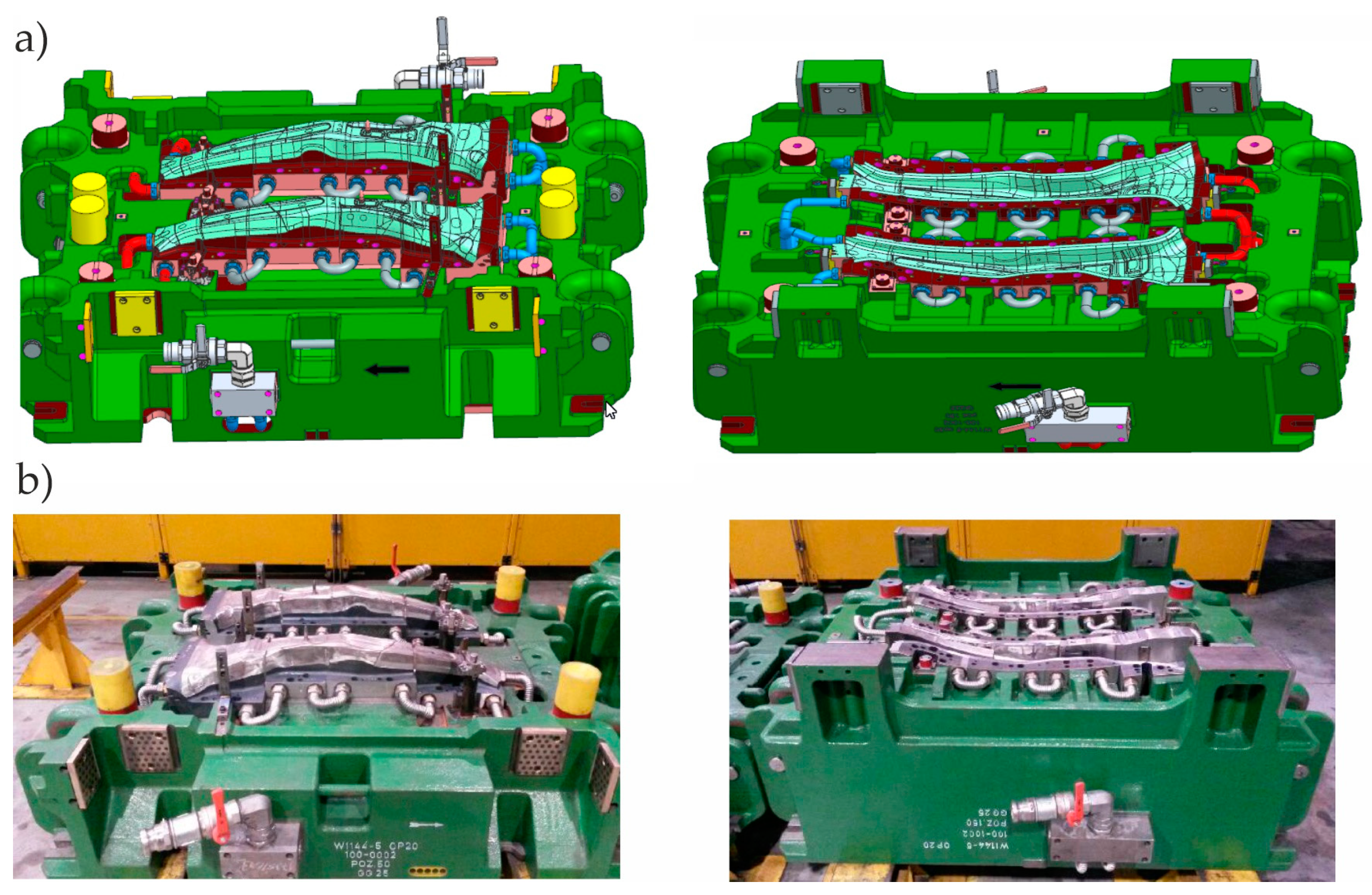
The hot stamping process control system was tested using a die (
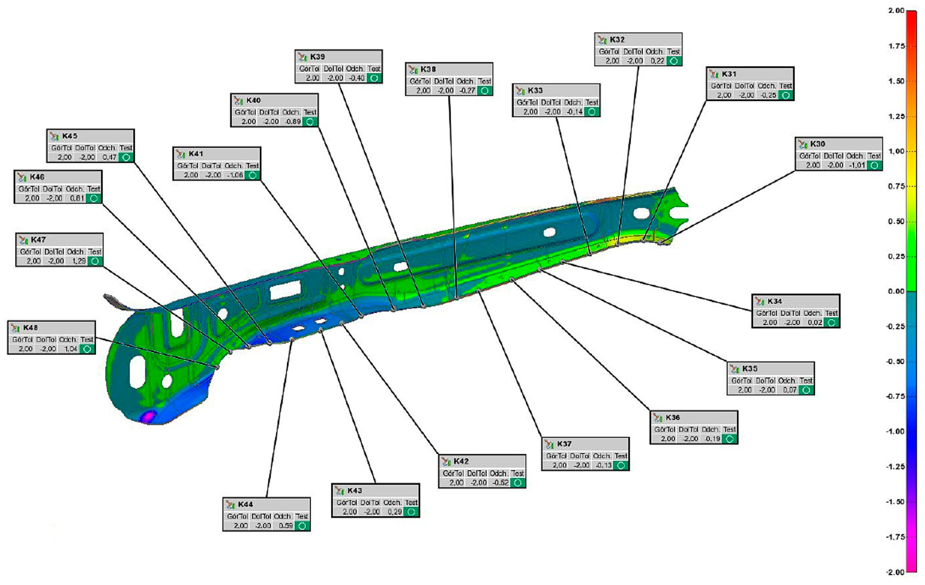
Figure 14) intended for the production of the B-pillar interior. The 2.2 mm thick drawpiece (
Figure 15) was made of 22MnB5 steel. It is steel intended for hot stamping, during which the drawpiece is shaped and quenched at the same time. It is assumed that after the pressing process, the drawpiece will have a martensitic structure and the following mechanical parameters: yield point Rp0.2 = 950–1200 MPa, strength limit Rm = 1300–1650 MPa, and hardness HV = 400–550.
During production trials, the following parameters of the technological process were controlled: the thickness of the blank, the temperature of the furnace chamber, the temperature of the atmosphere dew point in the furnace, the temperature of the blank before pressing, the location of the blank in the tool, and the temperature of the working surfaces. The initial values of these parameters and the permissible ranges of their variability (
Table 1) were selected on the basis of the analysis of computer simulation results of the stamping processes carried out in the Autoform package supported by the experience of engineers. During the simulations, the impact of, among others, the temperature of the blank after taking it out of the furnace and the temperature of the tool on the feasibility of the product was tested. Most of all, the value of thinning in the drawpiece and its hardness were assessed. An example of the analysis result for the most favourable set of process parameters is shown in
Figure 16.
All parameters recorded in
Table 1 were measured via appropriate measuring systems, described in Point 2. The parameter values were analysed in real time via the PLC, which was programmed to react to exceeding their permissible values.
Tests in production conditions consisted of the production of four series of 200 drawpieces each and testing the correct operation of the hot stamping process control system. When starting the first series of production, the optical system for measuring the position of the blank in the die detected an incorrect positioning and stopped the entire production process. It was necessary to correct the working trajectories of the R2 robot responsible for transferring the blank from the furnace to the die. In addition, during the production of all four production series, the limit values for any of the defined process parameters were not exceeded.

