


A Novel Measurement Approach to Experimentally Determine the Thermomechanical Properties of a Gas Foil Bearing Using a Specialized Sensing Foil Made of Inconel Alloy

 ,
,  ,
,  ,
,  , and
, and
Abstract
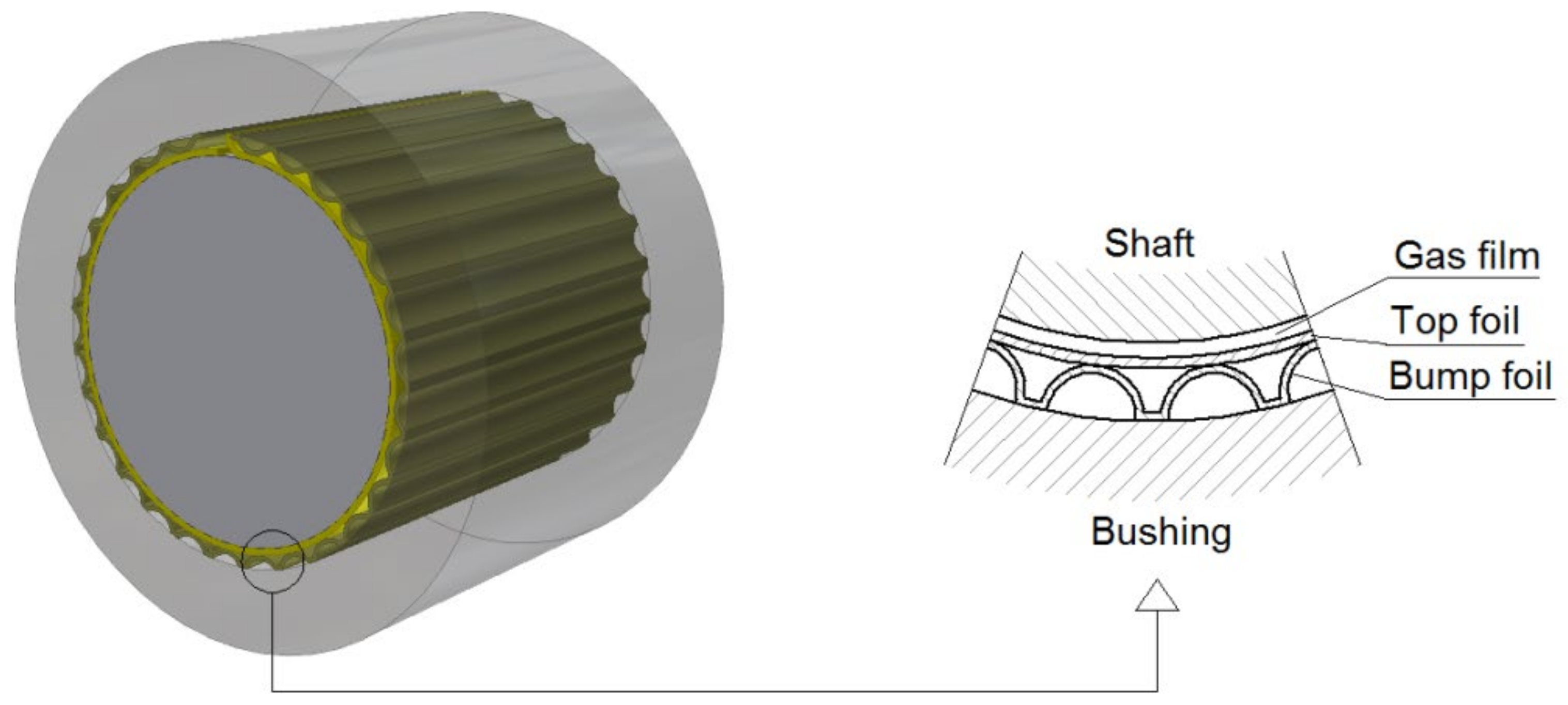
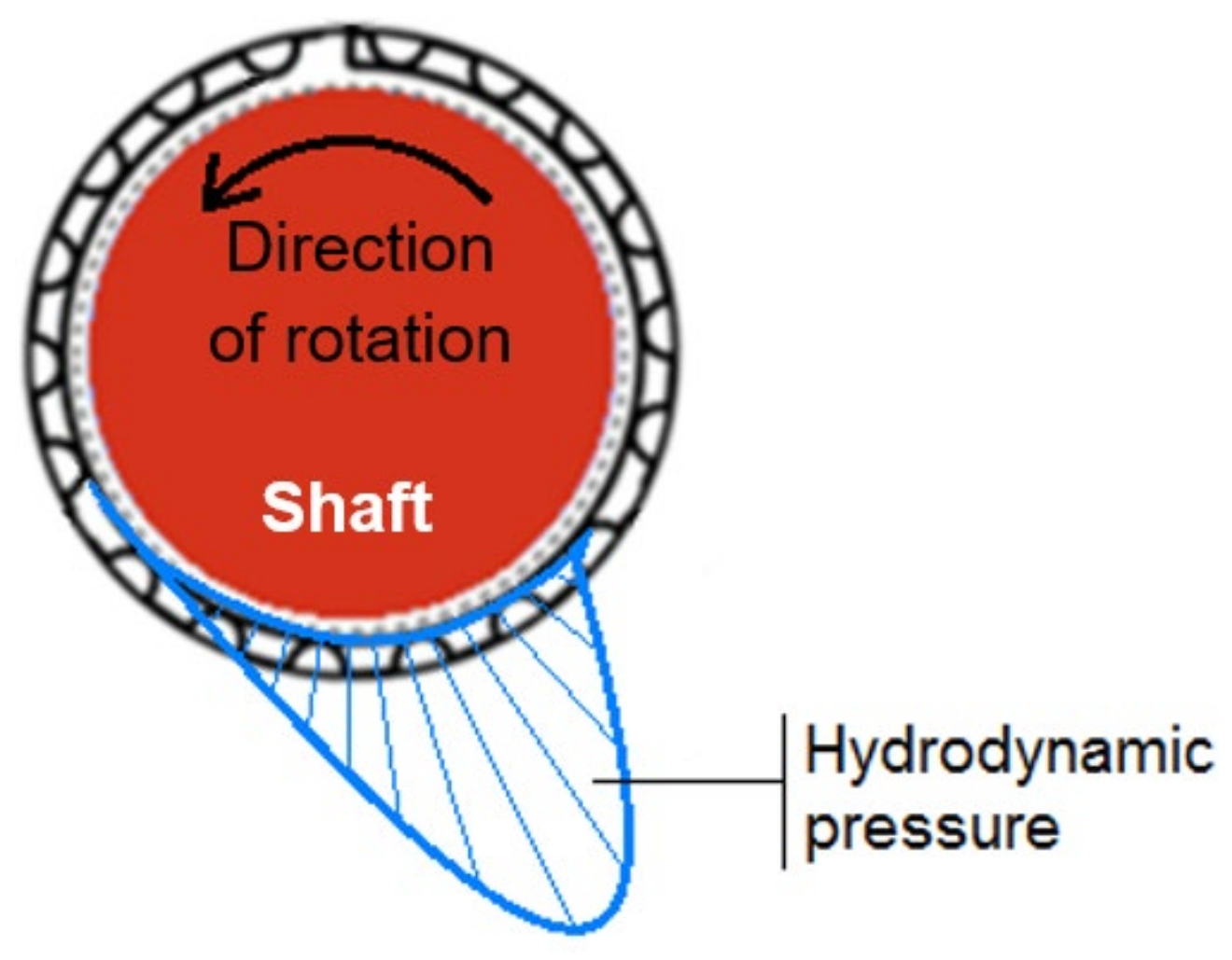
1. Introduction
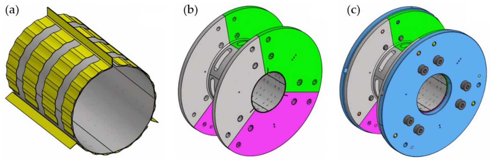
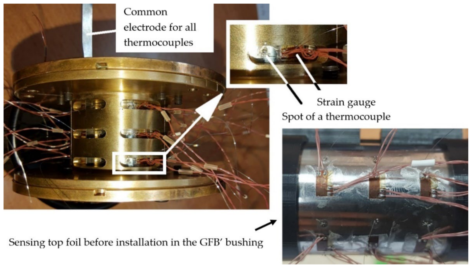
2. Novel Prototypes of GFB and Specialized Sensing Top Foil
3. Measurement System and Investigated GFB’s Operation Scenario
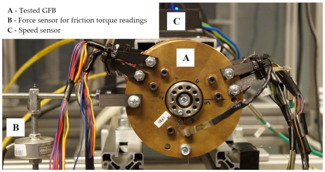
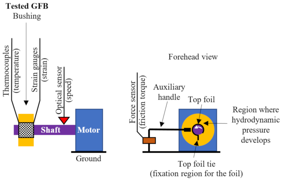
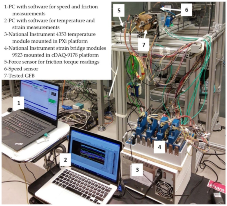
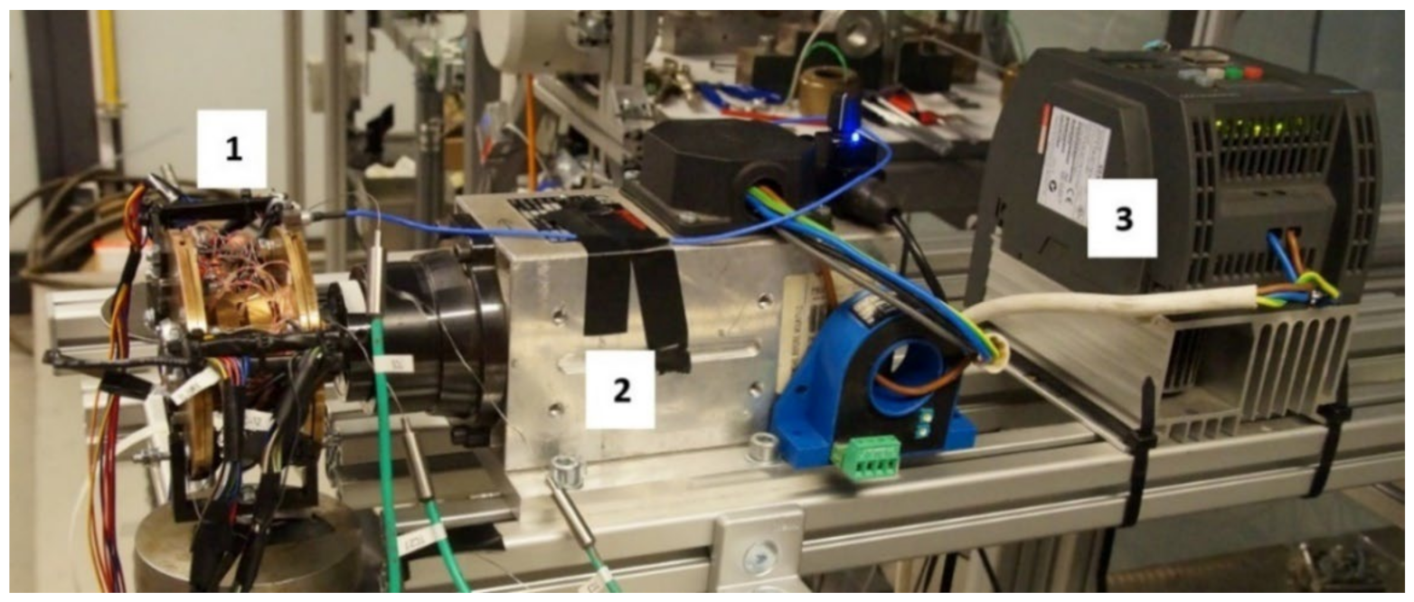
3.1. Experimental Test Stand

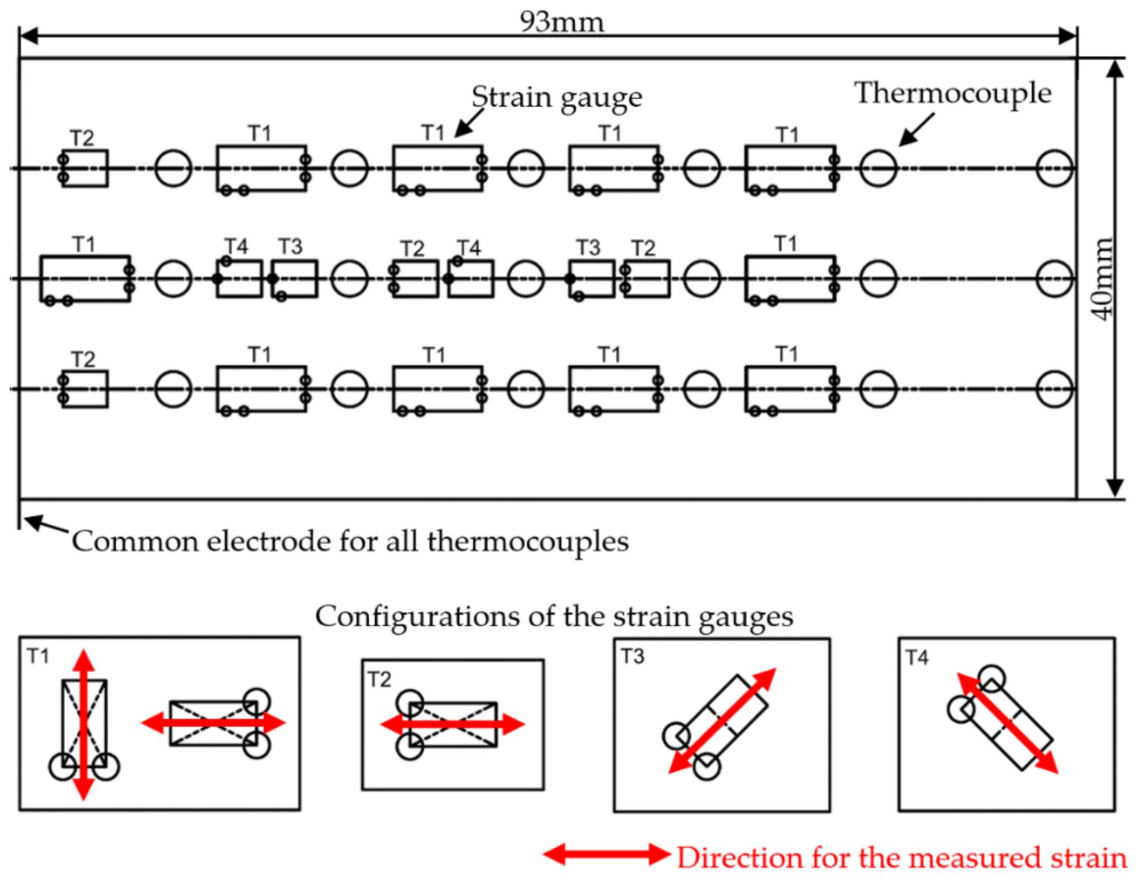
| Type of Sensor | Angular Position with Respect to the Localization of the Top Foil Tie [deg.] | Orientation of the Strain Component with Respect to Circumference [deg.] (Row along Circumference from the Top Foil Tie/Sensor Configuration) | Comments |
|---|---|---|---|
| Thermocouples | 42.5 | Not applicable | All thermocouples have a common electrode at the top foil tie |
| 102.5 | |||
| 162.5 | |||
| 222.5 | |||
| 282.5 | |||
| 342.5 | |||
| Strain gauges (sequentially denoted in Figure 10: SG1, … SG5) | 62.5 82.5 182.5 202.5 267.5 | −30 (Row 2/Configuration T4) 30 (Row 2/Configuration T3) 30 (Row 4/Configuration T3) 0 (Row 4/Configuration T2) 0 (Row 5/Configuration T1) | Skipped sensors:
|
| Please see Figure 5 for reference | |||

3.2. Measurement Scenario Selection
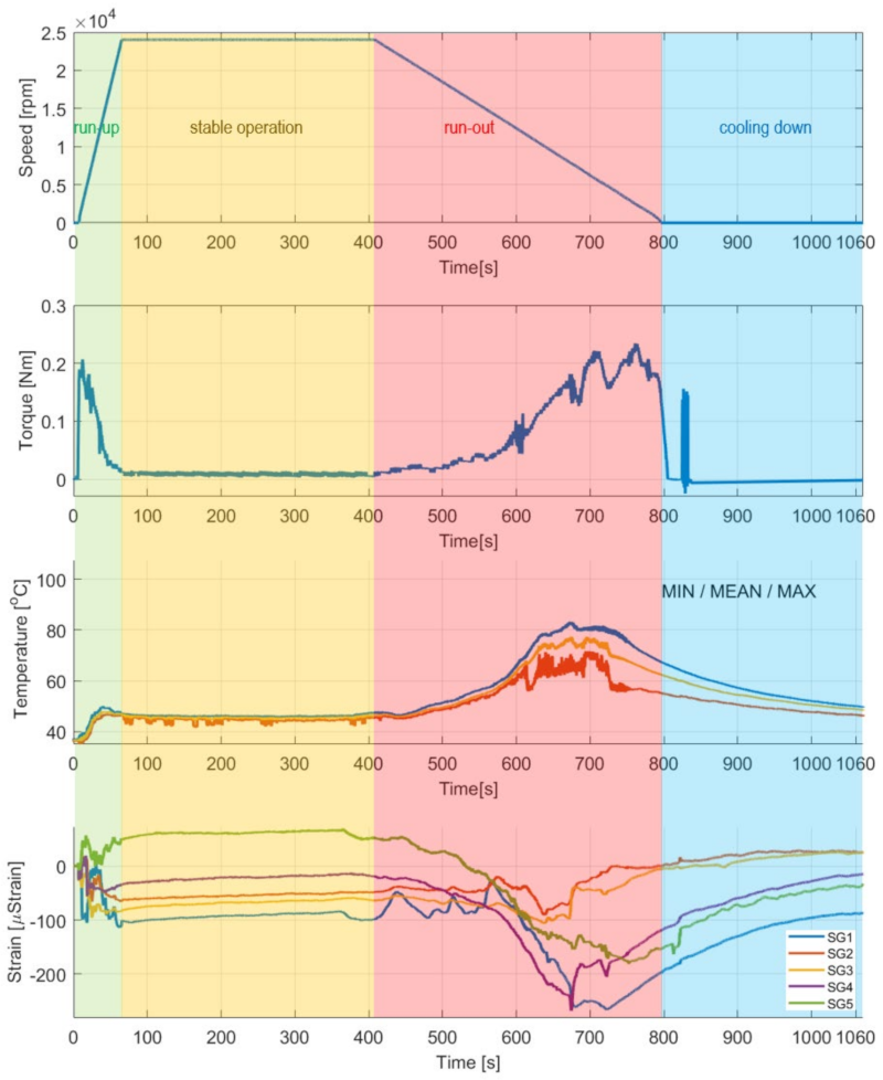
- Measurement process initialization at non-rotating shaft—lasting for 7 s;
- Run-up stage—for 60 s with the rotational acceleration 6.67 Hz/s (6.67 r/s2);
- Stage of stable operation at 24,000 r/min (24 krpm, i.e., 400 Hz)—for 340 s;
- Run-out stage—for 390 s with the rotational acceleration –1.03 Hz/s (–1.03 r/s2);
- Cooling down at a non-rotating shaft and the process of completing the measurements—for 273 s.
4. Experimental Results
4.1. Temporal Courses for the GFB’s Operational Characteristics
4.2. Circumferential Distributions of Temperature and Strain in the Top Foil
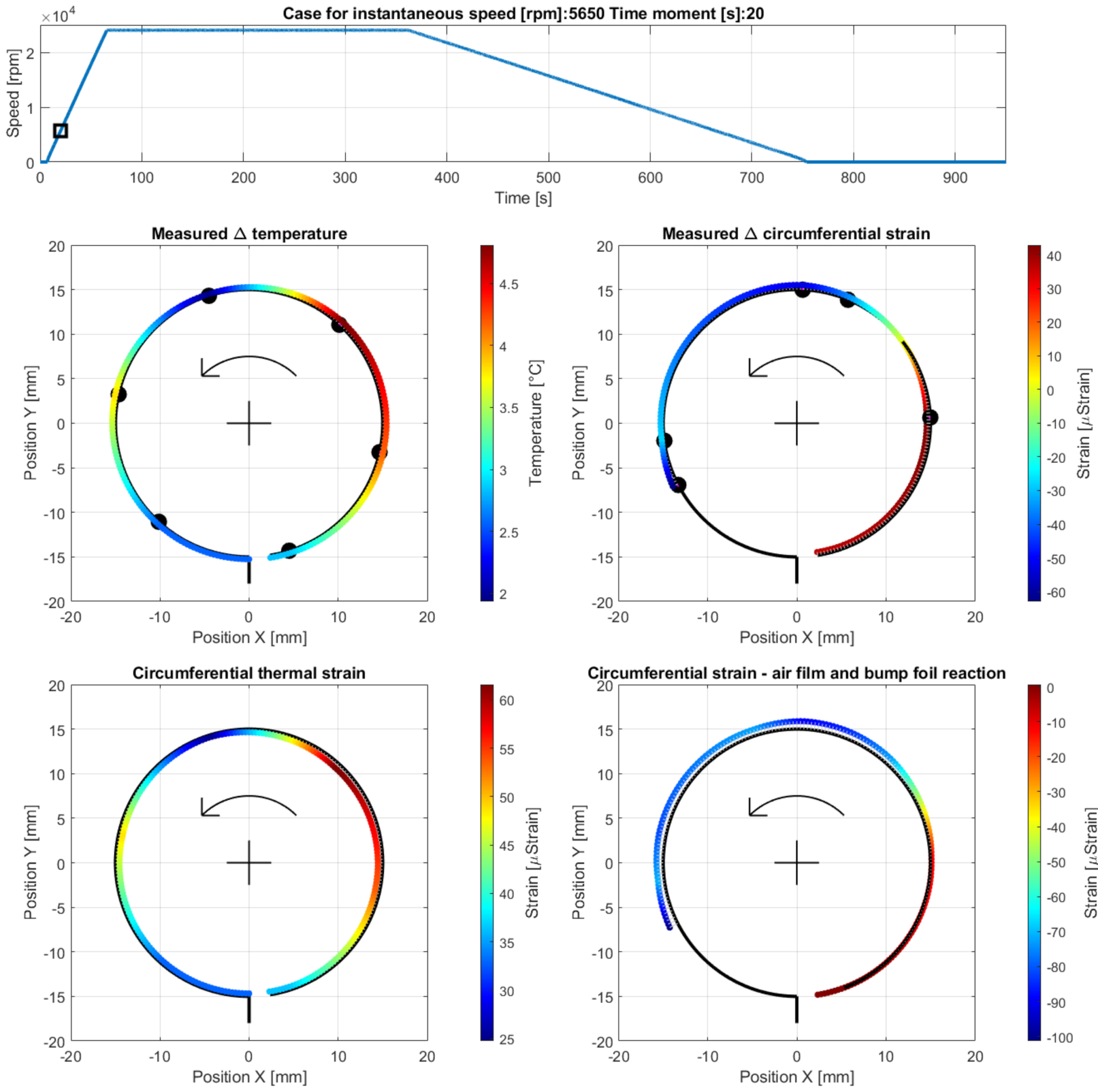
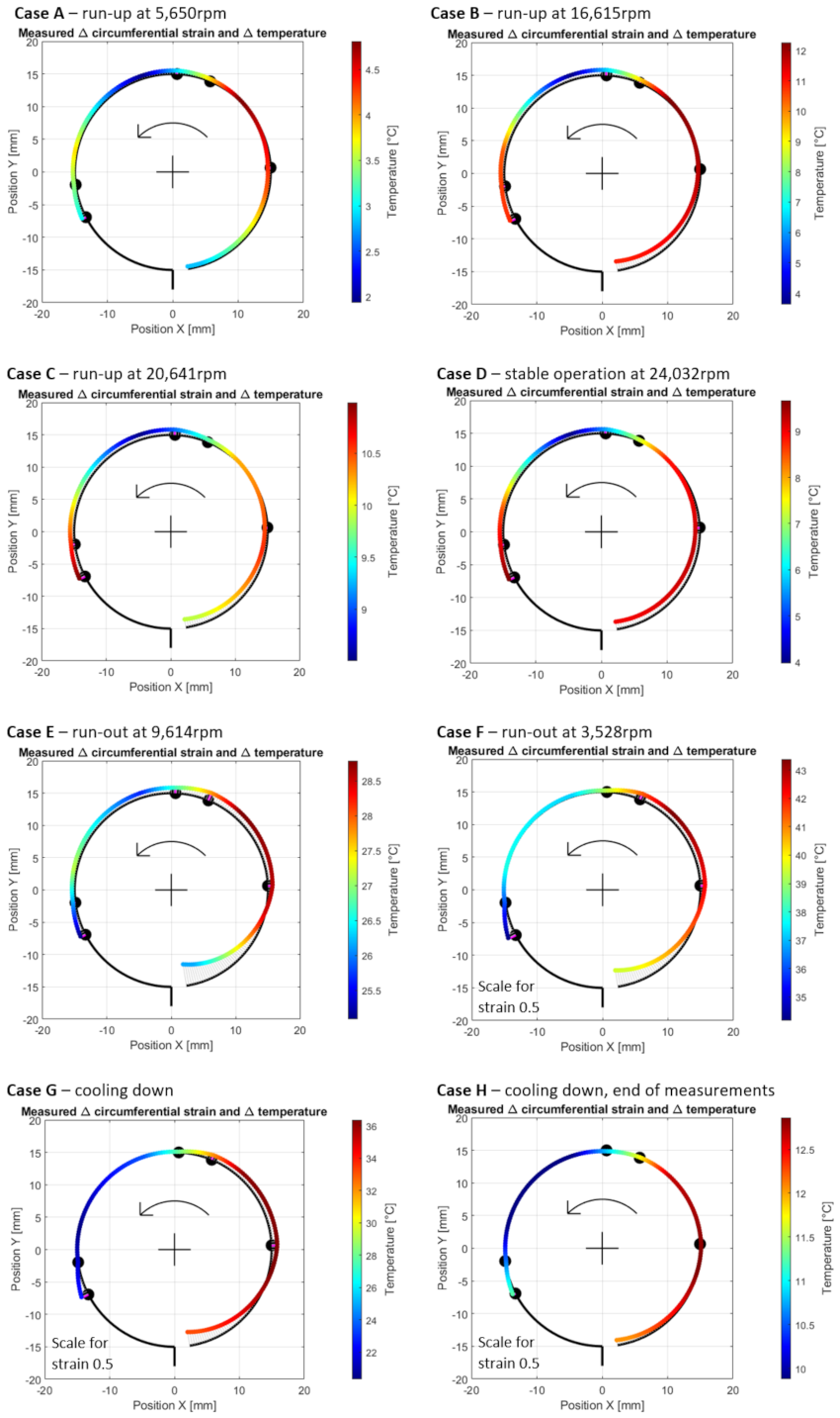
- Case A—phase of development of an air film during the run-up stage of the bearing’s operation at the measurement time moment 20 s, i.e., 13 s after the run-up stage was initiated (at 5650 rpm), specifically at the moment when the rates of the measured temperatures began to decrease. From that moment, the measured temperatures did not grow faster and faster anymore, until they finally reached the maximum level during the run-up stage of approximately 50 °C at 15,900 rpm. The results obtained for Case A are presented in Figure 11.
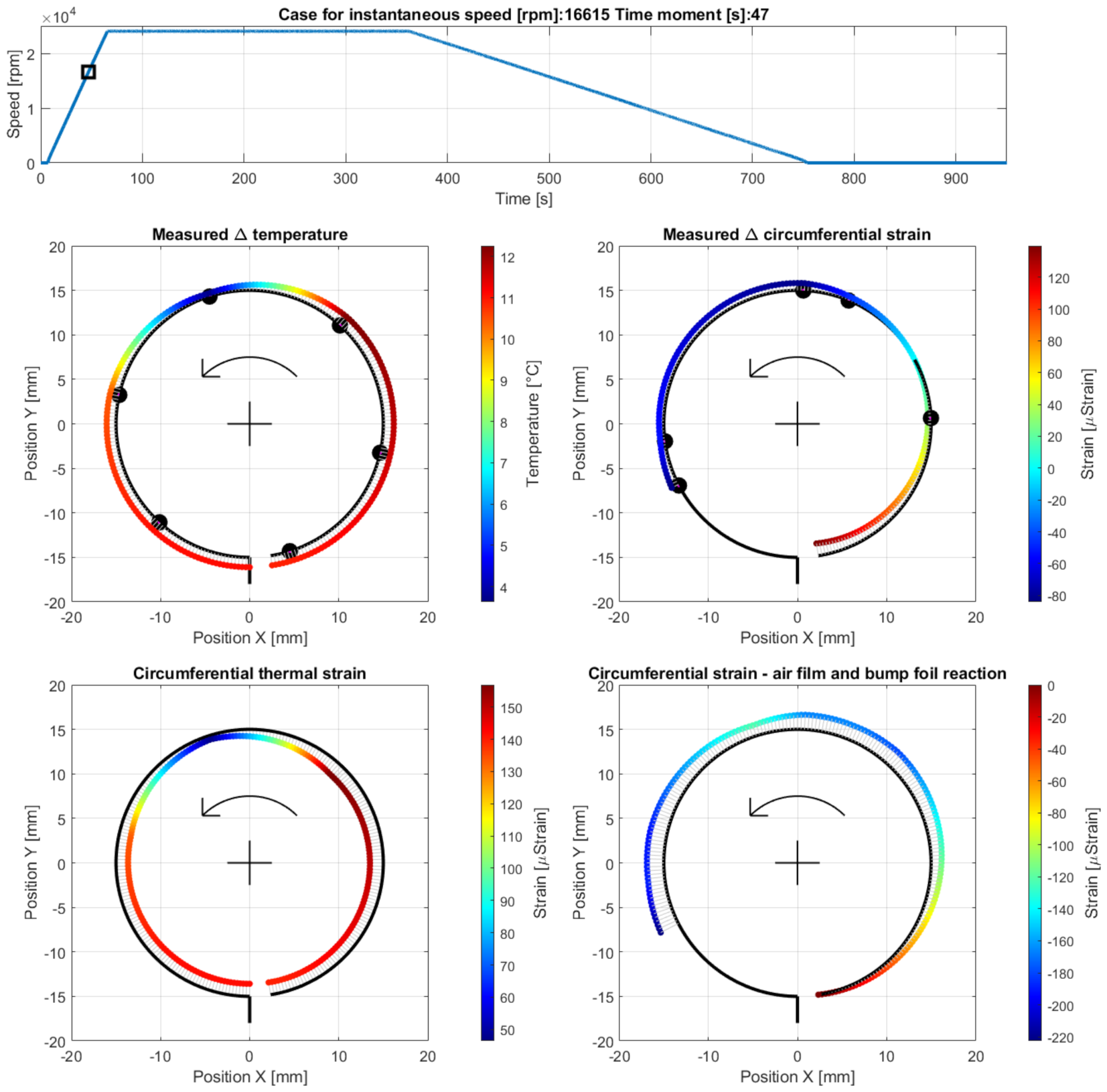
- Case B—operation with a fully developed air film during the run-up stage, at the measurement time moment 47 s, i.e., 40 s after the run-up stage was initiated (at 16,615 rpm) before the temperature along the top foil became homogenized; Figure 12 presents the results obtained for the current case.

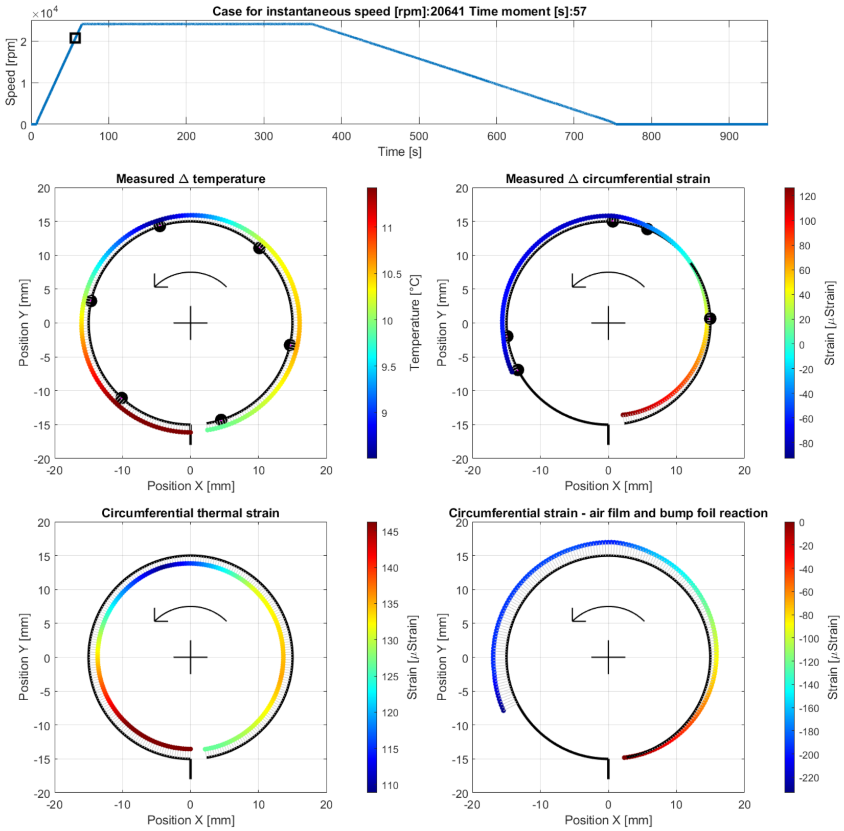
- Case C—operation with a fully developed air film during the run-up stage, at the measurement time moment 57 s, i.e., 50 s after the run-up stage was initiated (at 20,641 rpm) after the temperature in the top foil became homogenized (Figure 13).

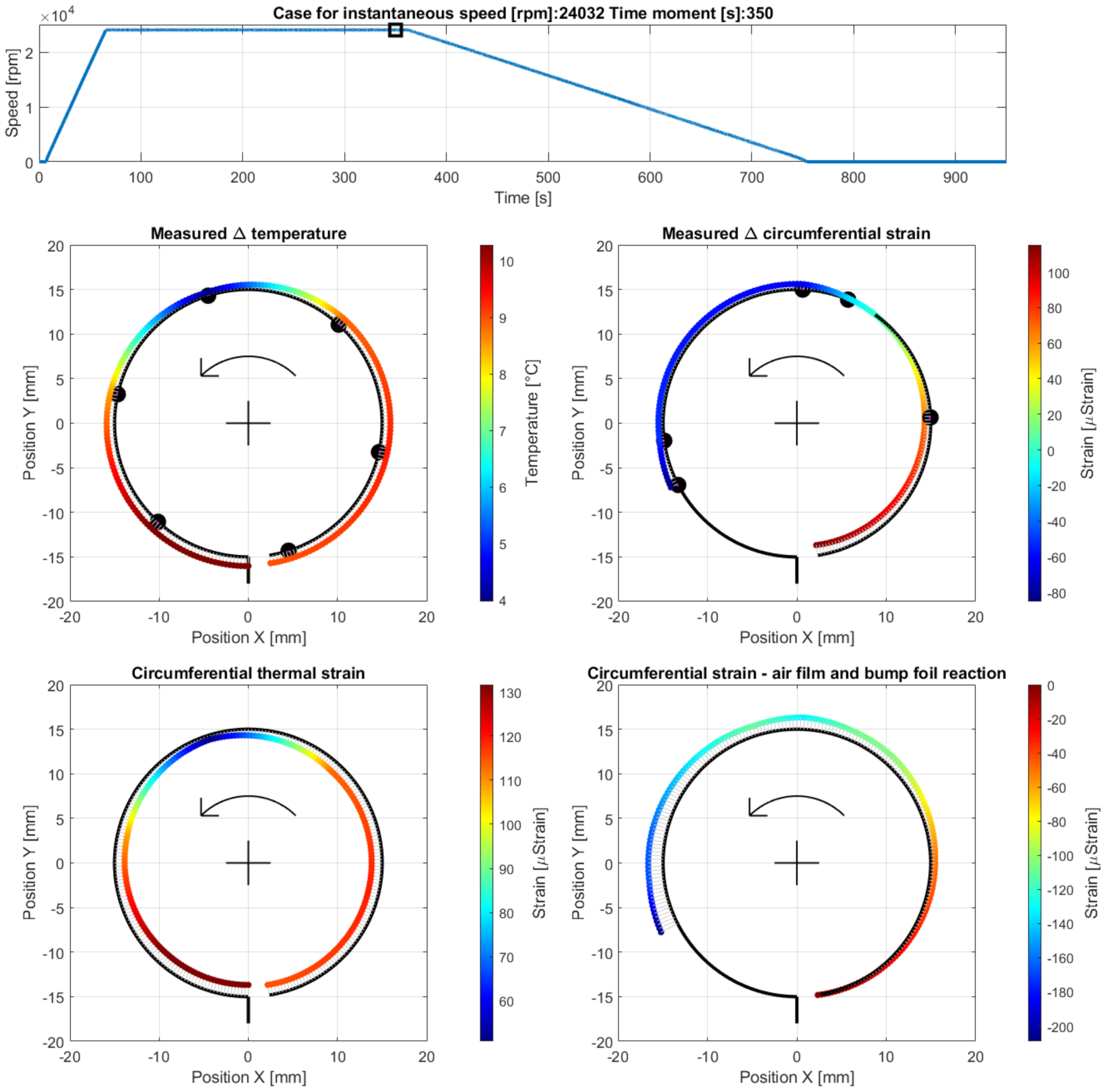
- Case D—operation at the end of the stage of stable operation, at the measurement time moment 350 s, i.e., 283 s after the run-up stage was initiated (at 24,032 rpm); The results are presented in Figure 14.

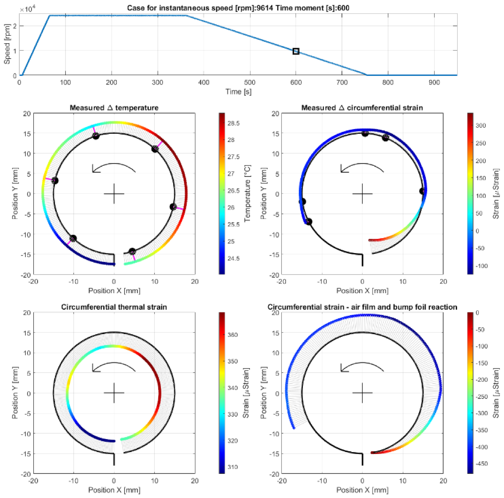
- Case E—operation at the run-out stage before a complete loss of the air film, at the measurement time moment 600 s, i.e., 193 s after the run-out stage was initiated (at 9614 rpm); The results are presented in Figure 15.

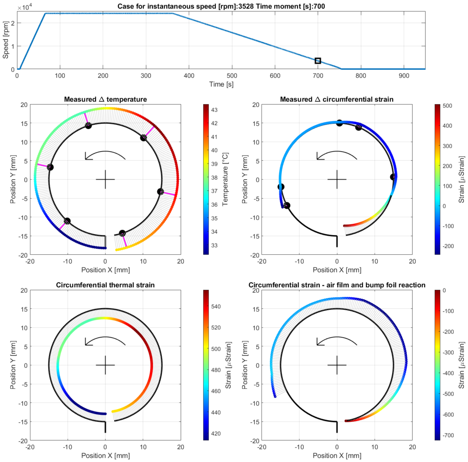
- Case F—operation at the end of the run-out stage after a complete loss of the air film, at the measurement time moment 700 s, i.e., 293 s after the run-out stage was initiated (at 3528 rpm). The results are presented in Figure 16.

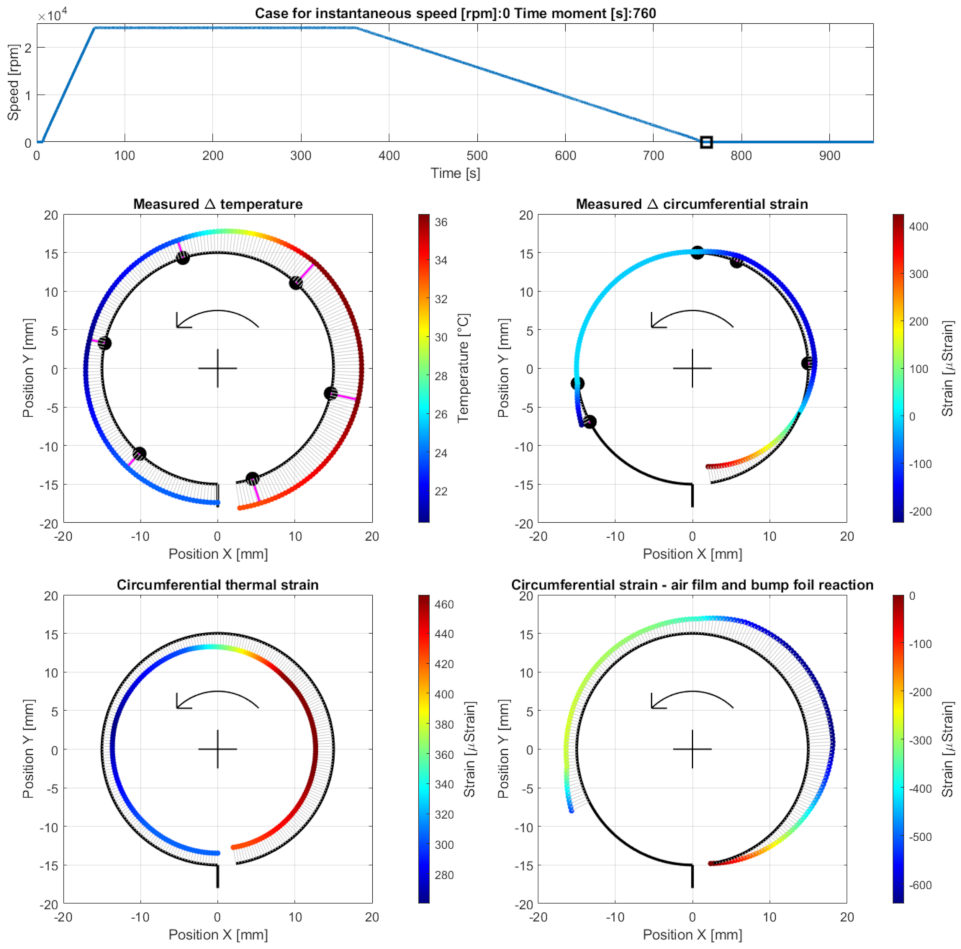
- Case G—initiation of the cooling down stage after the shaft’s stop, at the measurement time moment 760 s. The results are presented in Figure 17.

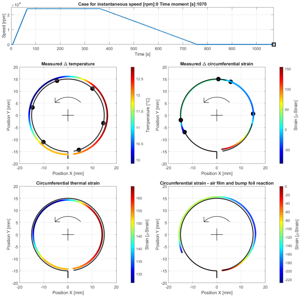
- Case H—end of the measurements during the cooling down stage at the time moment 1070 s. The results are presented in Figure 18.

5. Discussion
5.1. Cases A–C—Development of an Air Film during Run-Up Stage
5.2. Case D—Continuous Operation of the Bearing with a Stable Air Film
5.3. Cases E and F—Run-Out Stage and Gradual Loss of the Air Film
5.4. Cases G and H—Cooling Down
6. Summary and Concluding Remarks
Author Contributions
Funding
Data Availability Statement
Conflicts of Interest
References
- DellaCorte, C. Oil-Free shaft support system rotordynamics: Past, present and future challenges and opportunities. Mech. Syst. Signal Process. 2012, 29, 67–76. [Google Scholar] [CrossRef]
- Samanta, P.; Murmu, N.C.; Khonsari, M.M. The evolution of foil bearing technology. Tribol. Int. 2019, 135, 305–323. [Google Scholar] [CrossRef]
- DellaCorte, C.; Bruckner, R.J. Remaining technical challenges and future plans for oil-free turbomachinery. ASME J. Eng. Gas Turbines Power 2011, 133, 042502. [Google Scholar] [CrossRef]
- Żywica, G.; Bagiński, P. Investigation of gas foil bearings with an adaptive and non-linear structure. Acta Mech. Et Autom. 2019, 13, 5–10. [Google Scholar] [CrossRef]
- Yu, T.-Y.; Wang, P.-J. Simulation and experimental verification of dynamic characteristics on Gas Foil Thrust Bearings based on Multi-Physics Three-Dimensional Computer Aided Engineering methods. Lubricants 2022, 10, 222. [Google Scholar] [CrossRef]
- Żywica, G.; Bagiński, P.; Bogulicz, M.; Martowicz, A.; Roemer, J.; Kantor, S. Numerical identification of the dynamic characteristics of a nonlinear foil bearing structure: Effect of the excitation force amplitude and the assembly preload. J. Sound Vib. 2022, 520, 116663. [Google Scholar] [CrossRef]
- Martowicz, A.; Roemer, J.; Lubieniecki, M.; Żywica, G.; Bagiński, P. Experimental and numerical study on the thermal control strategy for a gas foil bearing enhanced with thermoelectric modules. Mechanical Syst. Signal Process. 2020, 138, 106581. [Google Scholar] [CrossRef]
- Mikolajczak, P. Vibration analysis of reconditioned high-speed electric motors. J. Vibroeng. 2019, 21, 1917–1927. [Google Scholar] [CrossRef]
- Weber, M.; Weigold, M. High speed synchronous reluctance drives for motor spindles. MM Sci. J. 2019, 4, 3323–3329. [Google Scholar] [CrossRef]
- Kim, T.H.; San Andres, L. Limits for high-speed operation of gas foil bearings. ASME J. Tribol. 2006, 128, 670–673. [Google Scholar] [CrossRef]
- Zhang, K.; Zhao, X.; Feng, K.; Zhao, Z. Thermohydrodynamic analysis and thermal management of hybrid bump-metal mesh foil bearings: Experimental tests and theoretical predictions. Int. J. Therm. Sci. 2018, 127, 91–104. [Google Scholar] [CrossRef]
- Zhang, C.; Ao, H.; Jiang, H.; Zhou, N. Investigations on start-up performances of novel hybrid metal rubber-bump foil bearings. Tribol. Int. 2021, 154, 106751. [Google Scholar] [CrossRef]
- San Andrés, L.; Chirathadam, T.A. Performance characteristics of metal mesh foil bearings: Predictions versus measurements. ASME J. Eng. Gas Turbines Power 2013, 135, 122503. [Google Scholar] [CrossRef]
- Feng, K.; Liu, Y.; Zhao, X.; Liu, W. Experimental evaluation of the structure characterization of a novel hybrid bump-metal mesh foil bearing. ASME J. Tribol. 2016, 138, 021702. [Google Scholar] [CrossRef]
- Hoffmann, R.; Liebich, R. Experimental and numerical analysis of the dynamic behaviour of a foil bearing structure affected by metal shims. Tribol. Int. 2017, 115, 378–388. [Google Scholar] [CrossRef]
- Feng, K.; Liu, W.; Yu, R.; Zhang, Z. Analysis and experimental study on a novel gas foil bearing with nested compression springs. Tribol. Int. 2017, 107, 65–76. [Google Scholar] [CrossRef]
- Martowicz, A.; Roemer, J.; Kantor, S.; Zdziebko, P.; Żywica, G.; Bagiński, P. Gas foil bearing technology enhanced with smart materials. Appl. Sci. 2021, 11, 2757. [Google Scholar] [CrossRef]
- Breńkacz, Ł.; Witanowski, Ł.; Drosińska-Komor, M.; Szewczuk-Krypa, N. Research and applications of active bearings: A state-of-the-art review. Mech. Syst. Signal Process. 2021, 151, 107423. [Google Scholar] [CrossRef]
- Park, J.; Sim, K. A feasibility study of controllable gas foil bearings with piezoelectric materials via rotordynamic model predictions. J. Eng. Gas Turbines Power 2019, 141, 021027. [Google Scholar] [CrossRef]
- Kikuchi, H.; Ibrahim, M.D.; Ochiai, M. Evaluation of lubrication performance of foil bearings with new texturing. Tribology Online 2019, 14, 339–344. [Google Scholar] [CrossRef]
- Lyu, P.; Feng, K.; Zhu, B.; Zhang, K.; Sun, D. The performance evaluation of the promising high-stability foil bearings basing with flexure pivot tilting pads. Mech. Syst. Signal Process. 2019, 134, 106313. [Google Scholar] [CrossRef]
- Pattnayak, M.R.; Pandey, R.K.; Dutt, J.K. Performance behaviours of a self-acting gas journal bearing with a new bore design. Tribol. Int. 2020, 151, 106418. [Google Scholar] [CrossRef]
- Guan, H.Q.; Feng, K.; Yu, K.; Cao, Y.L.; Wu, Y.H. Nonlinear dynamic responses of a rigid rotor supported by active bump-type foil bearings. Nonlinear Dyn. 2020, 100, 2241–2264. [Google Scholar] [CrossRef]
- Guan, H.Q.; Feng, K.; Cao, Y.L.; Huang, M.; Wu, Y.H.; Guo, Z.Y. Experimental and theoretical investigation of rotordynamic characteristics of a rigid rotor supported by an active bump-type foil bearing. J. Sound Vib. 2020, 466, 115049. [Google Scholar] [CrossRef]
- Howard, S.; Dellacorte, C.; Valco, M.J.; Prahl, J.M.; Heshmat, H. Dynamic stiffness and damping characteristics of a high-temperature air foil journal bearing. Tribol. Trans. 2008, 44, 657–663. [Google Scholar] [CrossRef]
- Kim, T.H.; Breedlove, A.W.; San Andres, L. Characterization of foil bearing structure for increasing shaft temperatures: Part I-Static load performance. In Proceeding of the ASME Turbo Expo GT2008, Berlin, Germany, 9–13 June 2008; p. 50567. [Google Scholar] [CrossRef]
- Kim, T.H.; Breedlove, A.W.; San Andres, L. Characterization of foil bearing structure at increasing temperatures: Static load and dynamic force performance. J. Tribol. 2009, 131, 041703. [Google Scholar] [CrossRef]
- San Andres, L.; Kim, T.H. Thermohydrodynamic analysis of bump type gas foil bearings: A model anchored to test data. ASME J. Tribol. 2010, 132, 011701. [Google Scholar] [CrossRef]
- Mahner, M.; Bauer, M.; Lehn, A.; Schweizer, B. An experimental investigation on the influence of an assembly preload on the hysteresis, the drag torque, the lift-off speed and the thermal behavior of three-pad air foil journal bearings. Tribol. Int. 2019, 137, 113–126. [Google Scholar] [CrossRef]
- Ghalayini, I.; Bonello, P. Nonlinear and linearised analyses of a generic rotor on single-pad foil-air bearings using Galerkin Reduction with different applied air film conditions. J. Sound Vib. 2022, 525, 116774. [Google Scholar] [CrossRef]
- Rieken, M.; Mahner, M.; Schweizer, B. Thermal optimization of air foil thrust bearing using different foil materials. J. Turbomach. 2020, 142, 101003. [Google Scholar] [CrossRef]
- Liu, X.; Li, C.; Du, J.; Nan, G. Thermal characteristics study of the bump foil thrust gas bearing. Appl. Sci. 2021, 11, 4311. [Google Scholar] [CrossRef]
- Kozanecki, Z.; Tkacz, E.; Łagodziński, J.; Miazga, K. Theoretical and experimental investigations of oil-free bearings and their application in diagnostics of high-speed turbomachinery. Key Eng. Mater. 2014, 588, 302–309. [Google Scholar] [CrossRef]
- Zhou, Y.; Shao, L.; Zhang, C.; Ji, F.; Liu, J.; Li, G.; Ding, S.; Zhang, Q.; Du, F. Numerical and experimental investigation on dynamic performance of bump foil journal bearing based on journal orbit. Chin. J. Aeronaut. 2021, 34, 586–600. [Google Scholar] [CrossRef]
- Yan, J.; Liu, Z.; Zhang, G.; Yu, X.; Xu, L. Feasibility study of a turbocharger rotor supported by air foil bearings with diameter of 17 mm focusing on rotordynamic performance. Proc. Inst. Mech. Eng. Part D J. Automot. Eng. 2018, 233, 1331–1344. [Google Scholar] [CrossRef]
- LaTray, N.; Kim, D.; Song, M. Static performance of a hydrostatic thrust foil bearing for large scale oil-free turbomachines. J. Eng. Gas Turbines Power 2021, 143, 041017. [Google Scholar] [CrossRef]
- Breńkacz, Ł.; Bagiński, P.; Żywica, G. Experimental research on foil vibrations in a gas foil bearing carried out using an ultra-high-speed camera. Appl. Sci. 2021, 11, 878. [Google Scholar] [CrossRef]
- Roemer, J.; Zdziebko, P.; Martowicz, A. Multifunctional bushing for gas foil bearing-test rig architecture and functionalities. Int. J. Multiphys. 2021, 15, 73–86. [Google Scholar] [CrossRef]
- Zdziebko, P.; Martowicz, A. Study on the temperature and strain fields in gas foil bearings–measurement method and numerical simulations. Eksploat. I Niezawodn.-Maint. Reliab. 2021, 23, 540–547. [Google Scholar] [CrossRef]
- Żywica, G.; Bagiński, P.; Banaszek, S. Experimental studies on foil bearing with a sliding coating made of synthetic material. J. Tribol. 2016, 138, 011301. [Google Scholar] [CrossRef]
- Lubieniecki, M.; Roemer, J.; Martowicz, A.; Wojciechowski, K.; Uhl, T. A multi-point measurement method for thermal characterization of foil bearings using customized thermocouples. J. Electron. Mater. 2016, 45, 1473–1477. [Google Scholar] [CrossRef]
- Bagiński, P.; Żywica, G. Experimental study of various low-friction coatings for high-temperature gas foil bearings under cold-start conditions. ASME J. Eng. Gas Turbines Power 2022, 144, 081007. [Google Scholar] [CrossRef]
- Martowicz, A.; Zdziebko, P.; Roemer, J.; Zywica, G. ; Baginski, P. Thermal characterization of a Gas Foil Bearing—A novel method of experimental identification of the temperature field based on integrated thermocouples measurements. Sensors 2022, 22, 5718. [Google Scholar] [CrossRef] [PubMed]
- Carpino, M.; Medvetz, L.A.; Peng, J.P. Effects of Membrane Stresses in the Prediction of Foil Bearing Performance. Tribol. Trans. 1994, 37, 43–50. [Google Scholar] [CrossRef]
- Hryniewicz, P.; Wodtke, M.; Olszewski, A.; Rzadkowski, R. Structural Properties of Foil Bearings: A Closed-Form Solution Validated with Finite Element Analysis. Tribol. Trans. 2009, 52, 435–446. [Google Scholar] [CrossRef]


| Parameter/Characteristics | Value/Description |
|---|---|
| Shaft’s journal nominal diameter | 30 mm |
| Bushing’s inner nominal diameter | 31 mm |
| Bearing width | 40 mm |
| Foil thickness | 0.1 mm |
| Characteristics of the bump foils: | |
| Bump pitch | 4.8 mm |
| Bump height | 0.4 mm |
| Bump length | 3.4 mm |
| Number of bumps in segment | 7 |
| Number of segments | 4 |
| Number of foils | 3 |
| Theoretical nominal clearance | 0.02 mm |
Disclaimer/Publisher’s Note: The statements, opinions and data contained in all publications are solely those of the individual author(s) and contributor(s) and not of MDPI and/or the editor(s). MDPI and/or the editor(s) disclaim responsibility for any injury to people or property resulting from any ideas, methods, instructions or products referred to in the content. |
© 2022 by the authors. Licensee MDPI, Basel, Switzerland. This article is an open access article distributed under the terms and conditions of the Creative Commons Attribution (CC BY) license (https://creativecommons.org/licenses/by/4.0/).
Share and Cite
Martowicz, A.; Roemer, J.; Zdziebko, P.; Żywica, G.; Bagiński, P.; Andrearczyk, A. A Novel Measurement Approach to Experimentally Determine the Thermomechanical Properties of a Gas Foil Bearing Using a Specialized Sensing Foil Made of Inconel Alloy. Materials 2023, 16, 145. https://doi.org/10.3390/ma16010145
Martowicz A, Roemer J, Zdziebko P, Żywica G, Bagiński P, Andrearczyk A. A Novel Measurement Approach to Experimentally Determine the Thermomechanical Properties of a Gas Foil Bearing Using a Specialized Sensing Foil Made of Inconel Alloy. Materials. 2023; 16(1):145. https://doi.org/10.3390/ma16010145
Chicago/Turabian StyleMartowicz, Adam, Jakub Roemer, Paweł Zdziebko, Grzegorz Żywica, Paweł Bagiński, and Artur Andrearczyk. 2023. "A Novel Measurement Approach to Experimentally Determine the Thermomechanical Properties of a Gas Foil Bearing Using a Specialized Sensing Foil Made of Inconel Alloy" Materials 16, no. 1: 145. https://doi.org/10.3390/ma16010145
APA StyleMartowicz, A., Roemer, J., Zdziebko, P., Żywica, G., Bagiński, P., & Andrearczyk, A. (2023). A Novel Measurement Approach to Experimentally Determine the Thermomechanical Properties of a Gas Foil Bearing Using a Specialized Sensing Foil Made of Inconel Alloy. Materials, 16(1), 145. https://doi.org/10.3390/ma16010145