
New Chemically Resistant Coating Systems with Progressive Incorporation of Hazardous Waste in Polyurethane and Epoxy Matrices


Abstract
:1. Introduction
2. Materials
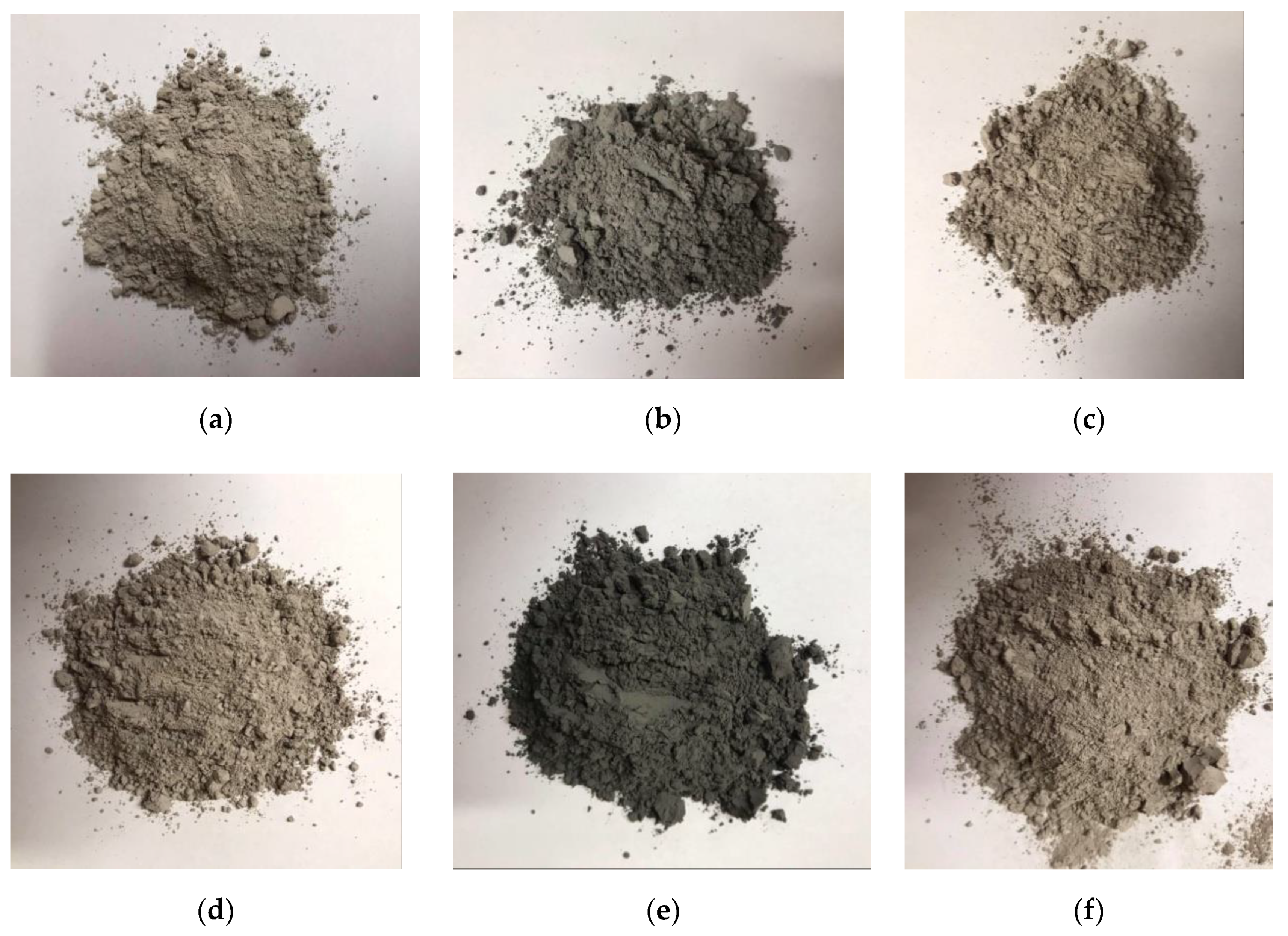
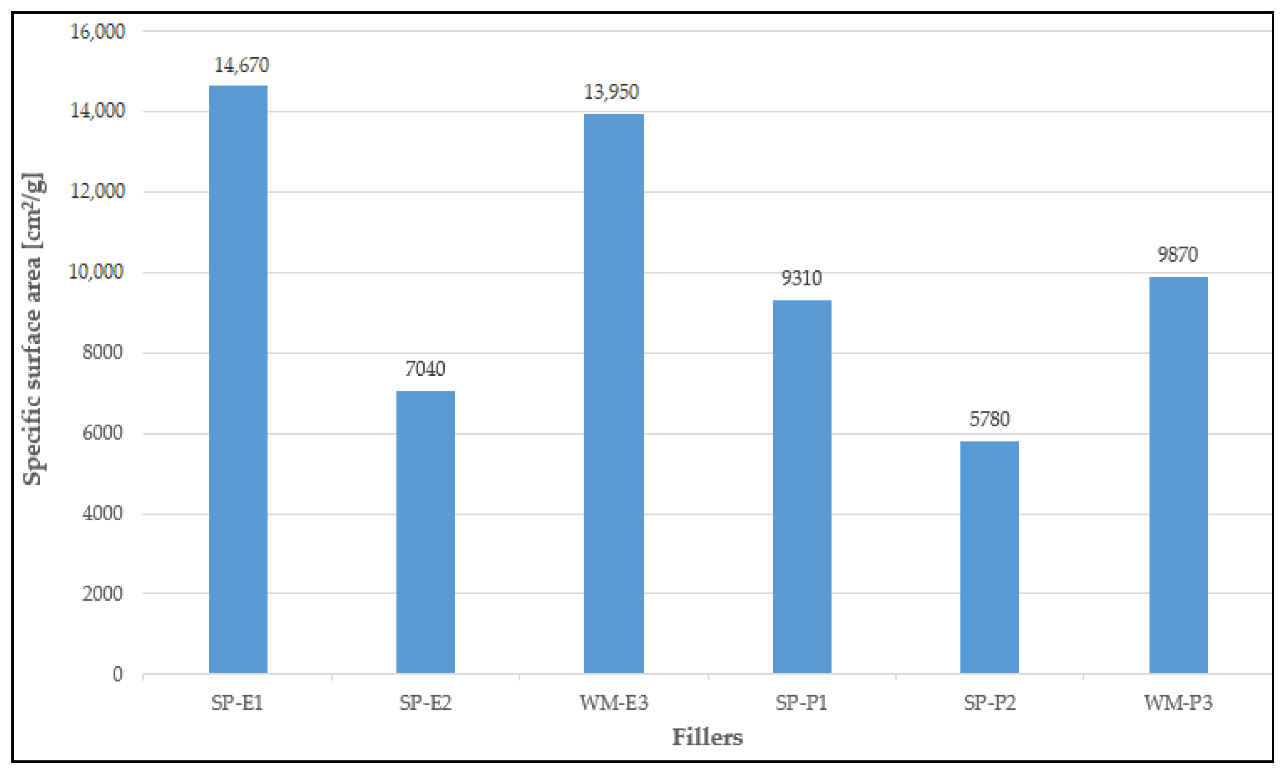
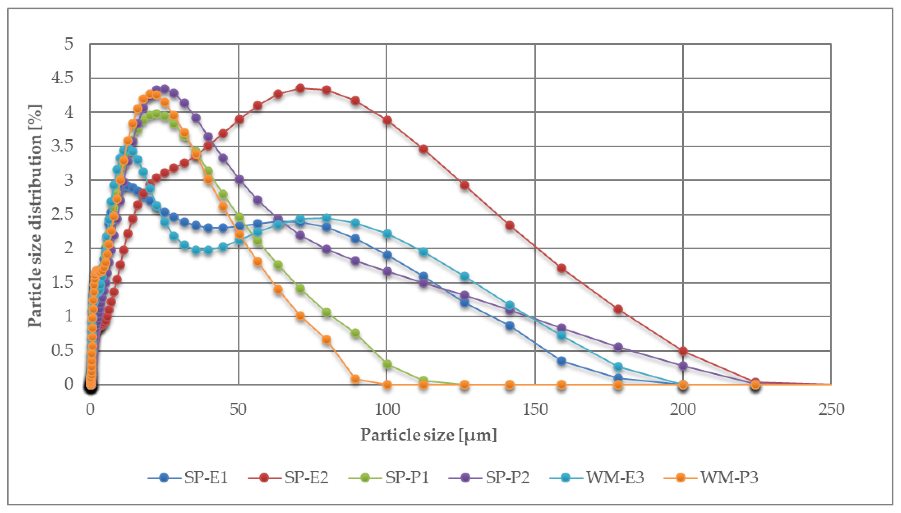
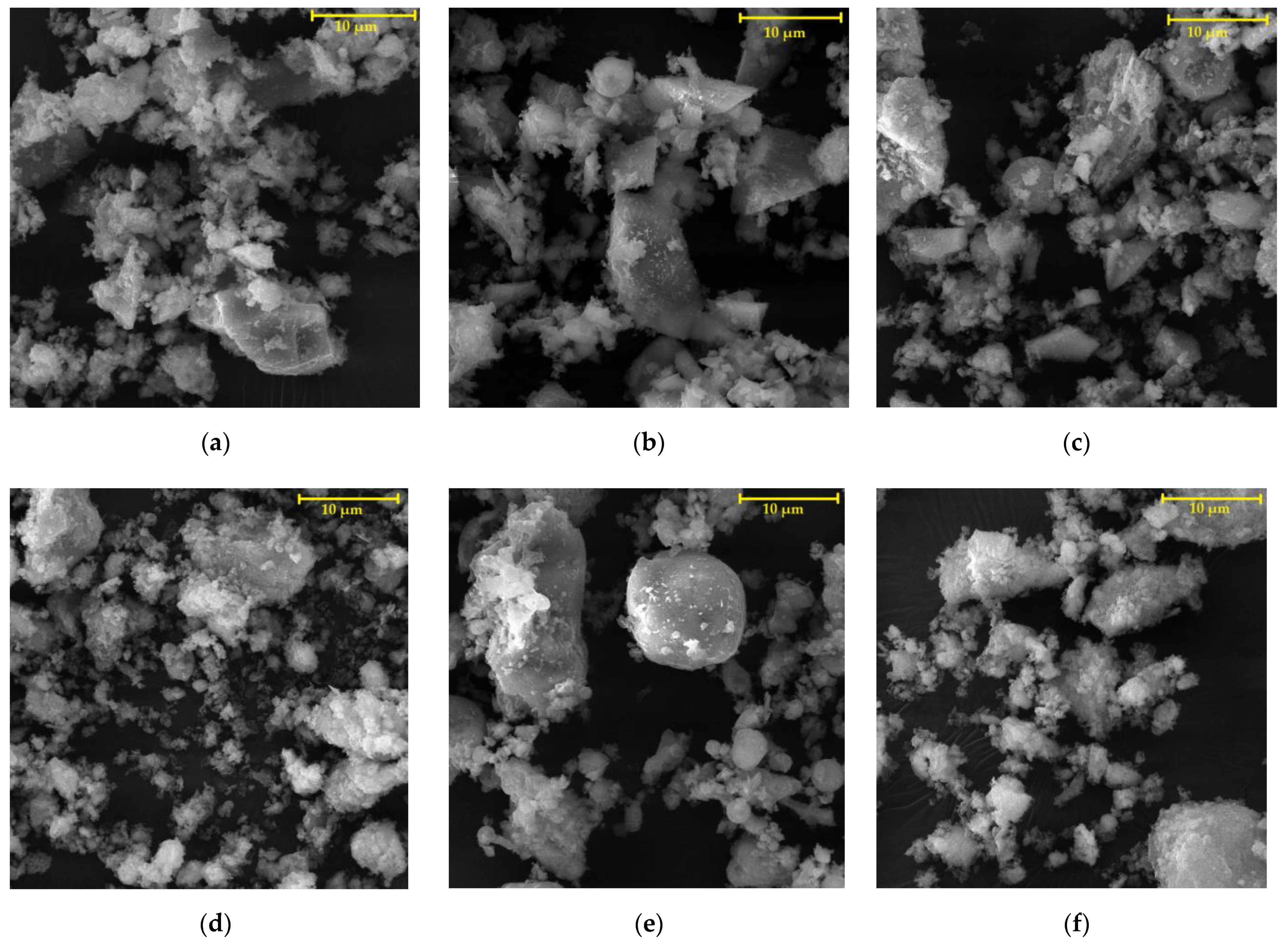
2.1. Fillers
2.2. Polymer Binders
2.3. Formulations of Coating Systems
3. Methods
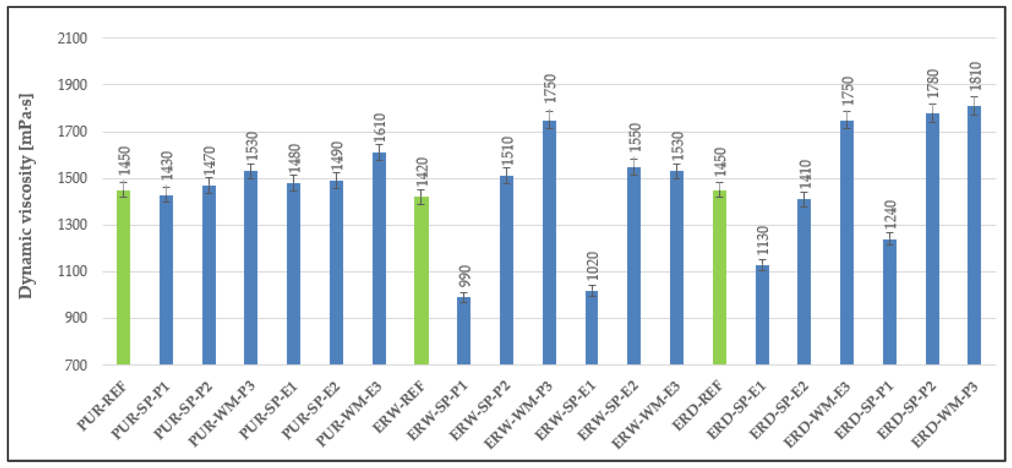
3.1. Dynamic Viscosity
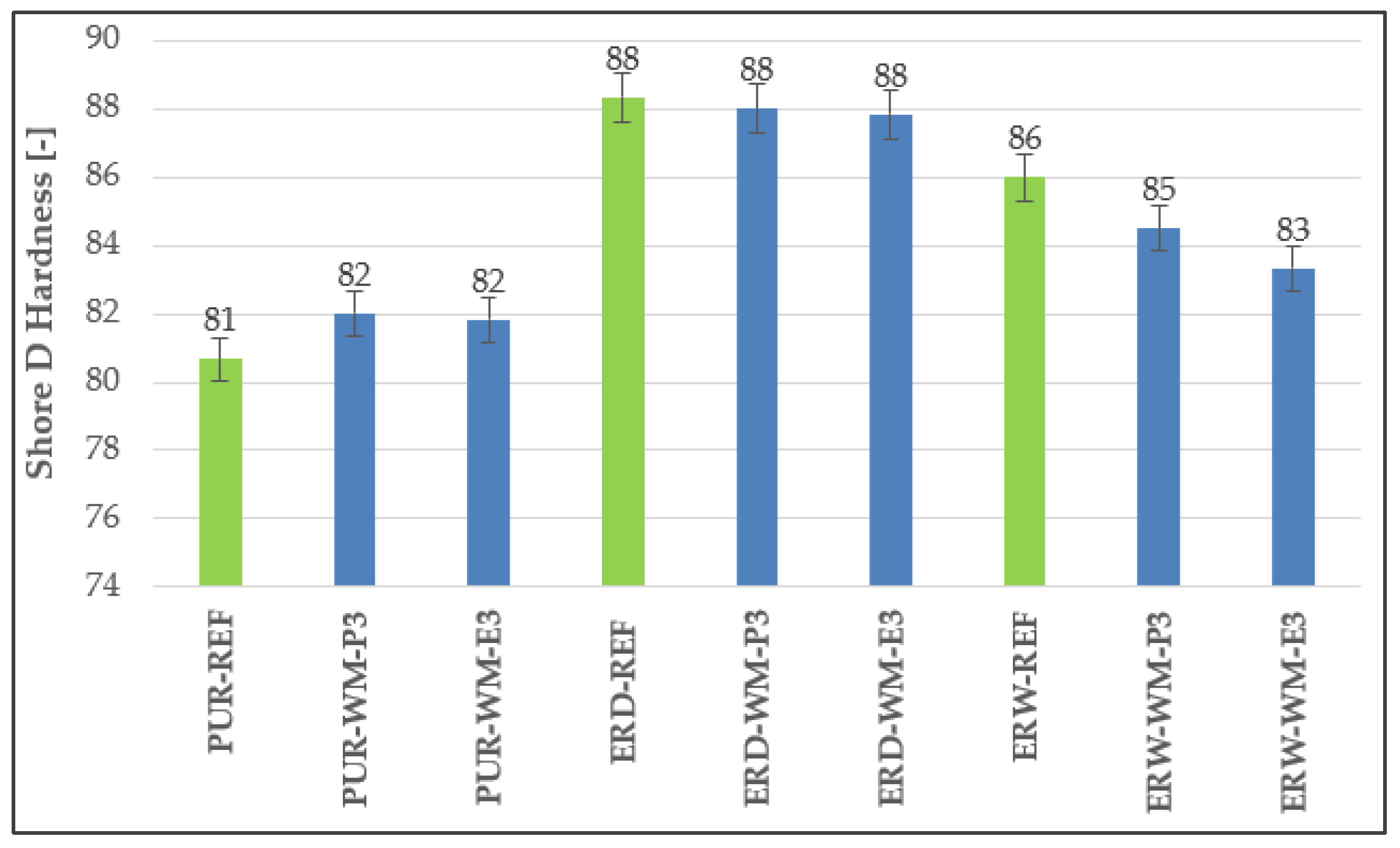
3.2. Hardness
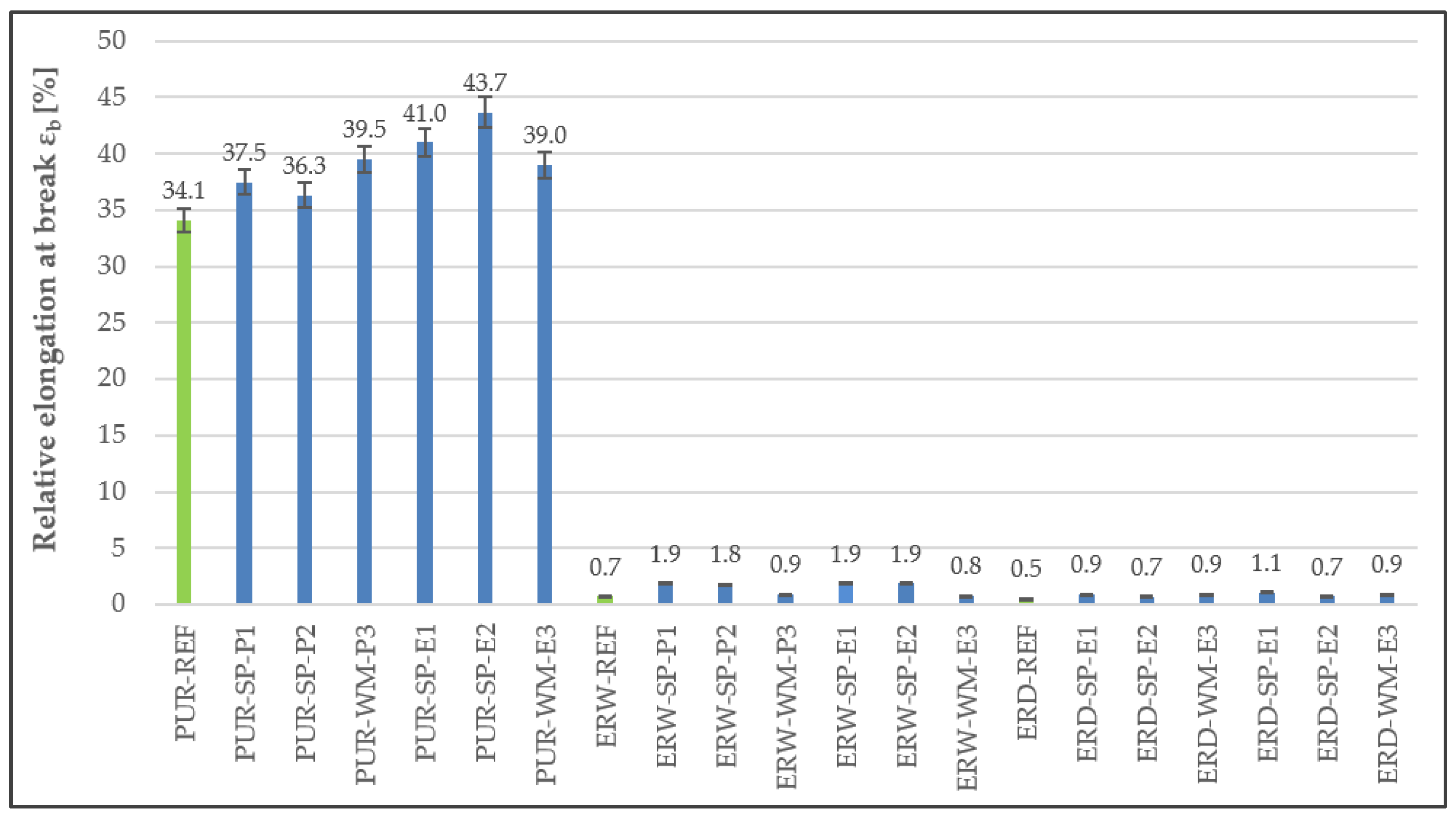
3.3. Tensile Properties
3.4. Adhesion to the Substrate
3.5. Impact Resistance
3.6. Flexural Modulus
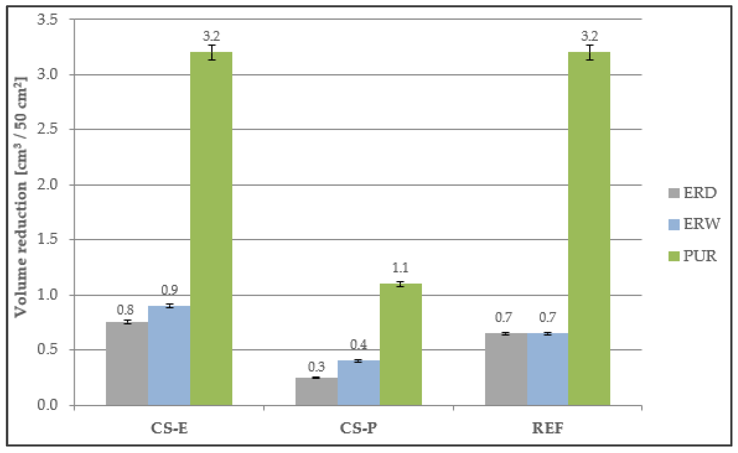
3.7. Abrasion Resistance
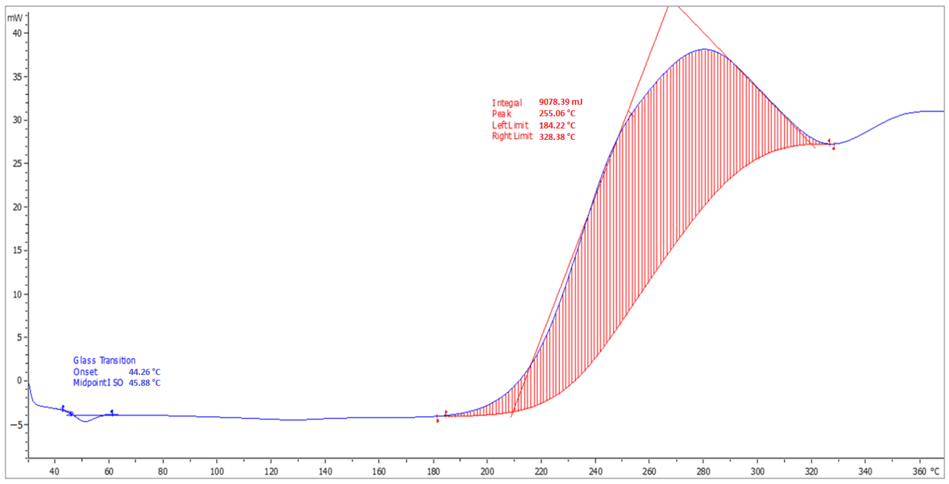
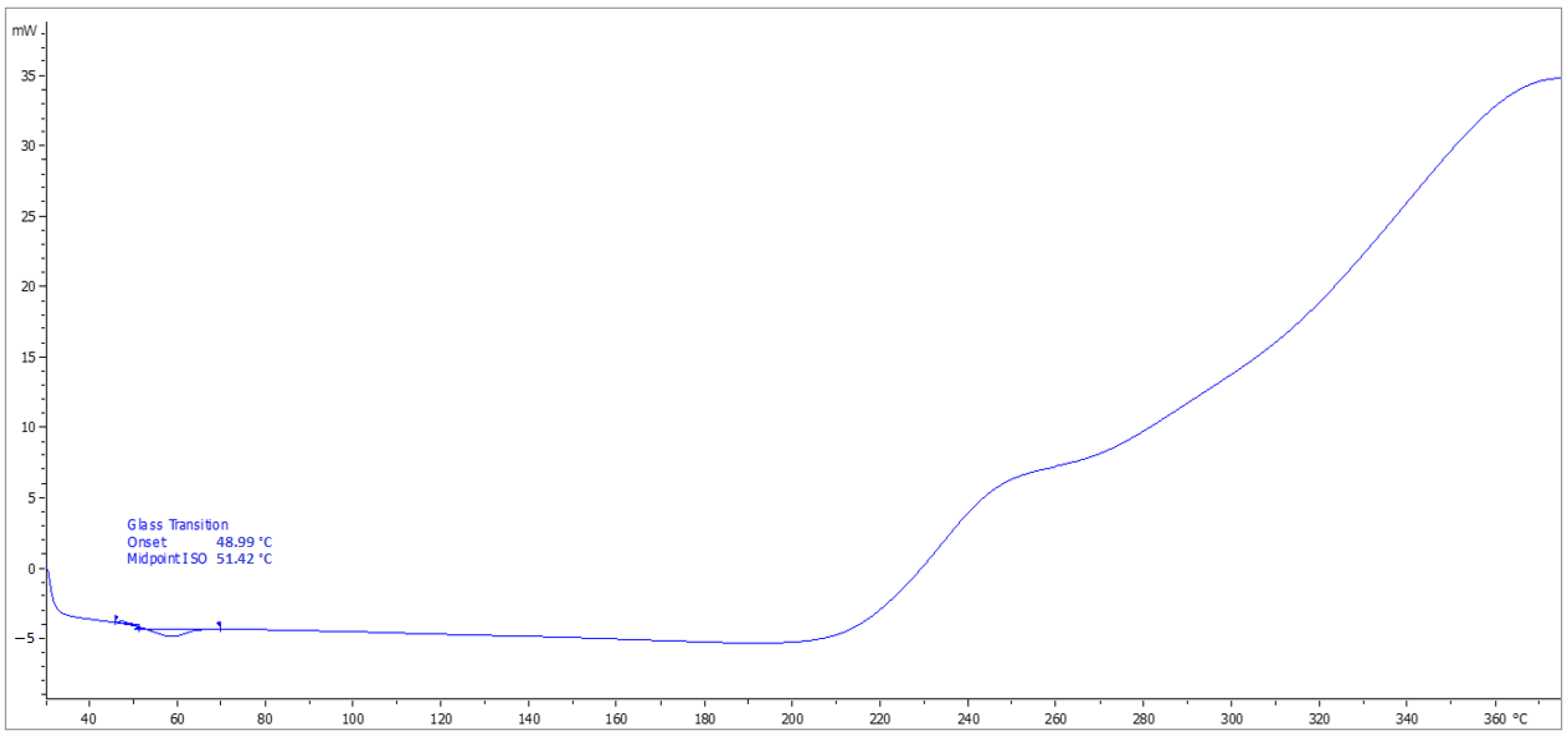
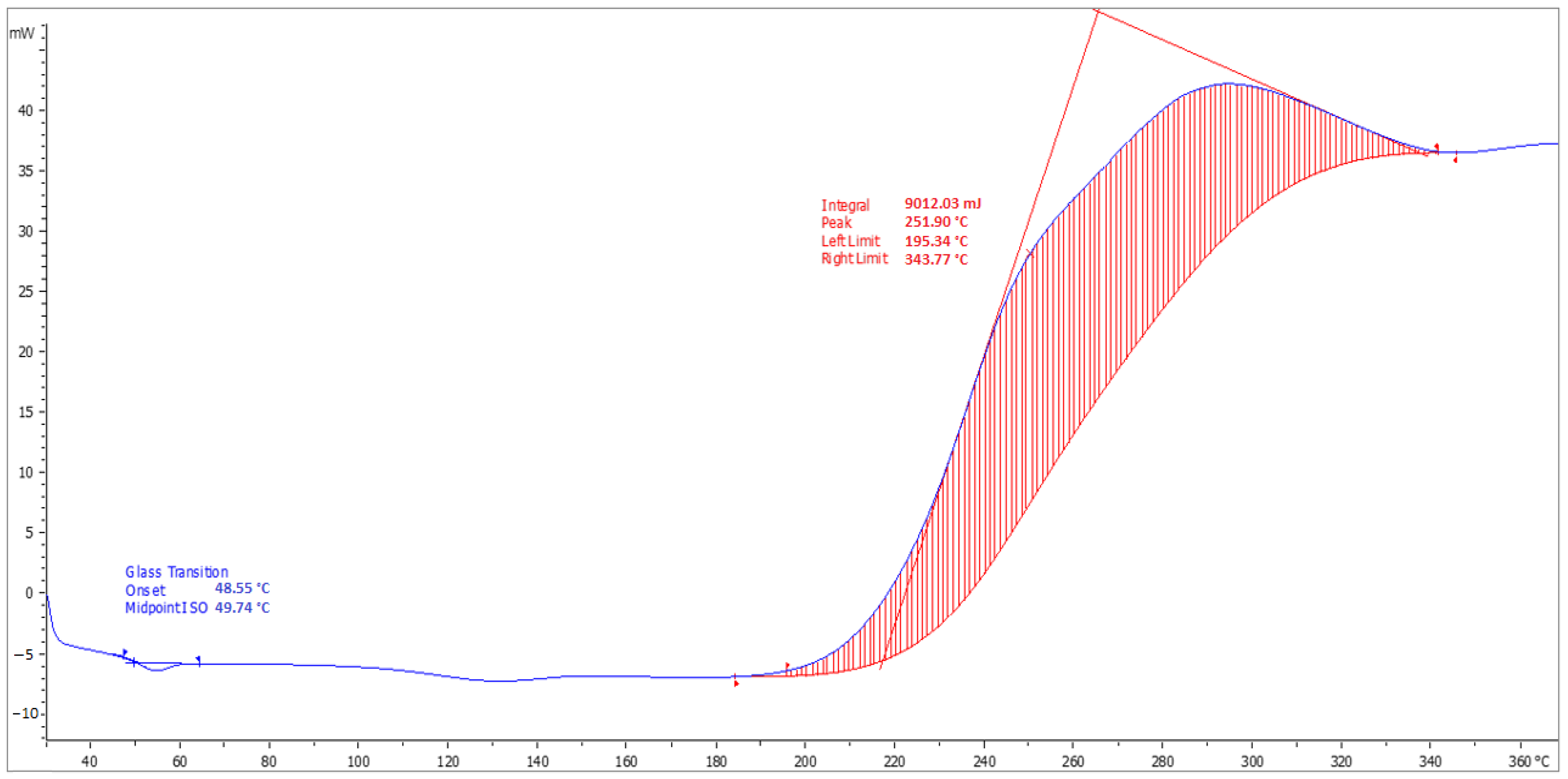
3.8. Determination of Tg
3.9. Chemical Resistance
4. Results and Discussion
4.1. Dynamic Viscosity
4.2. Hardness
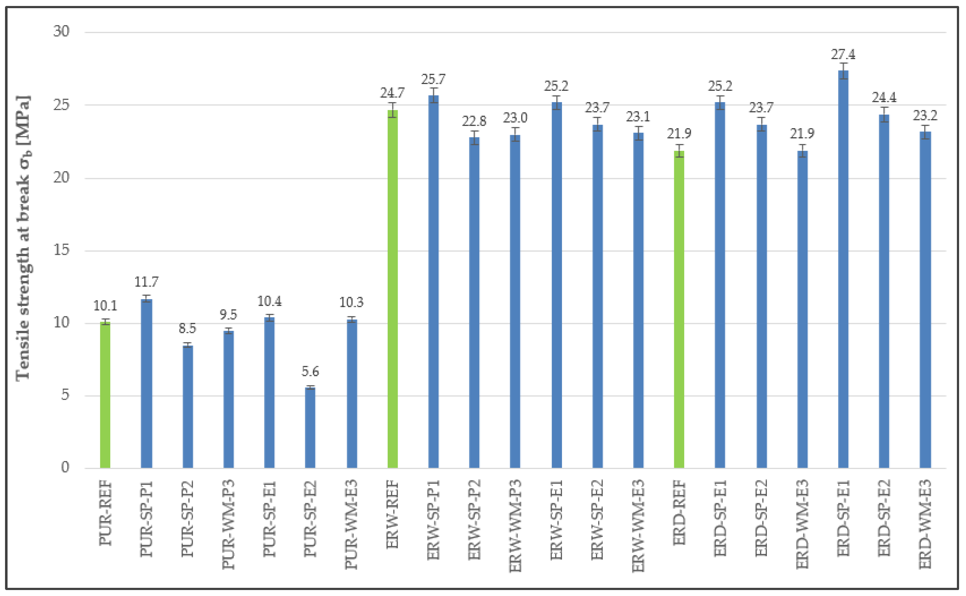
4.3. Tensile Properties
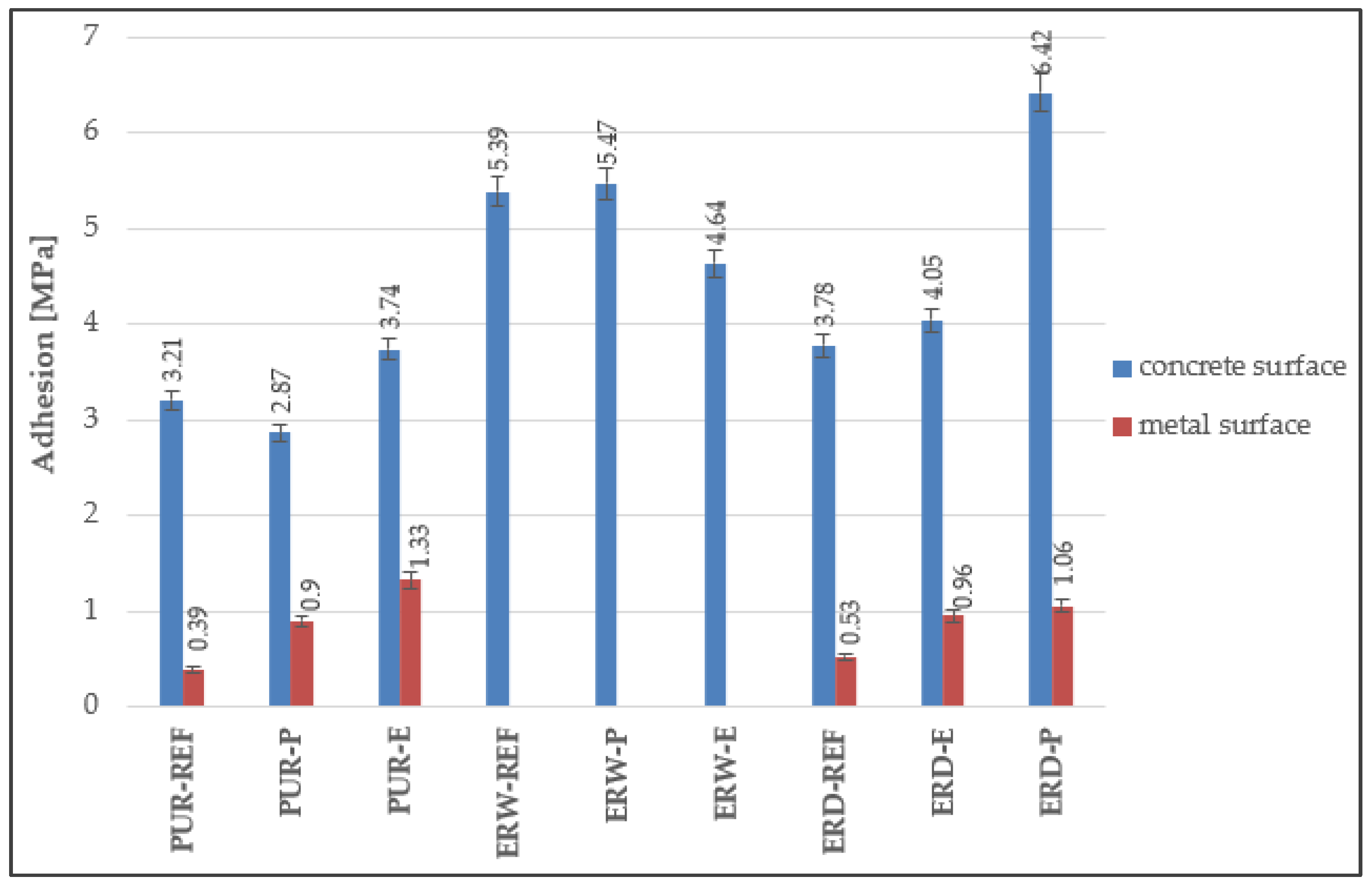
4.4. Adhesion to the Substrate
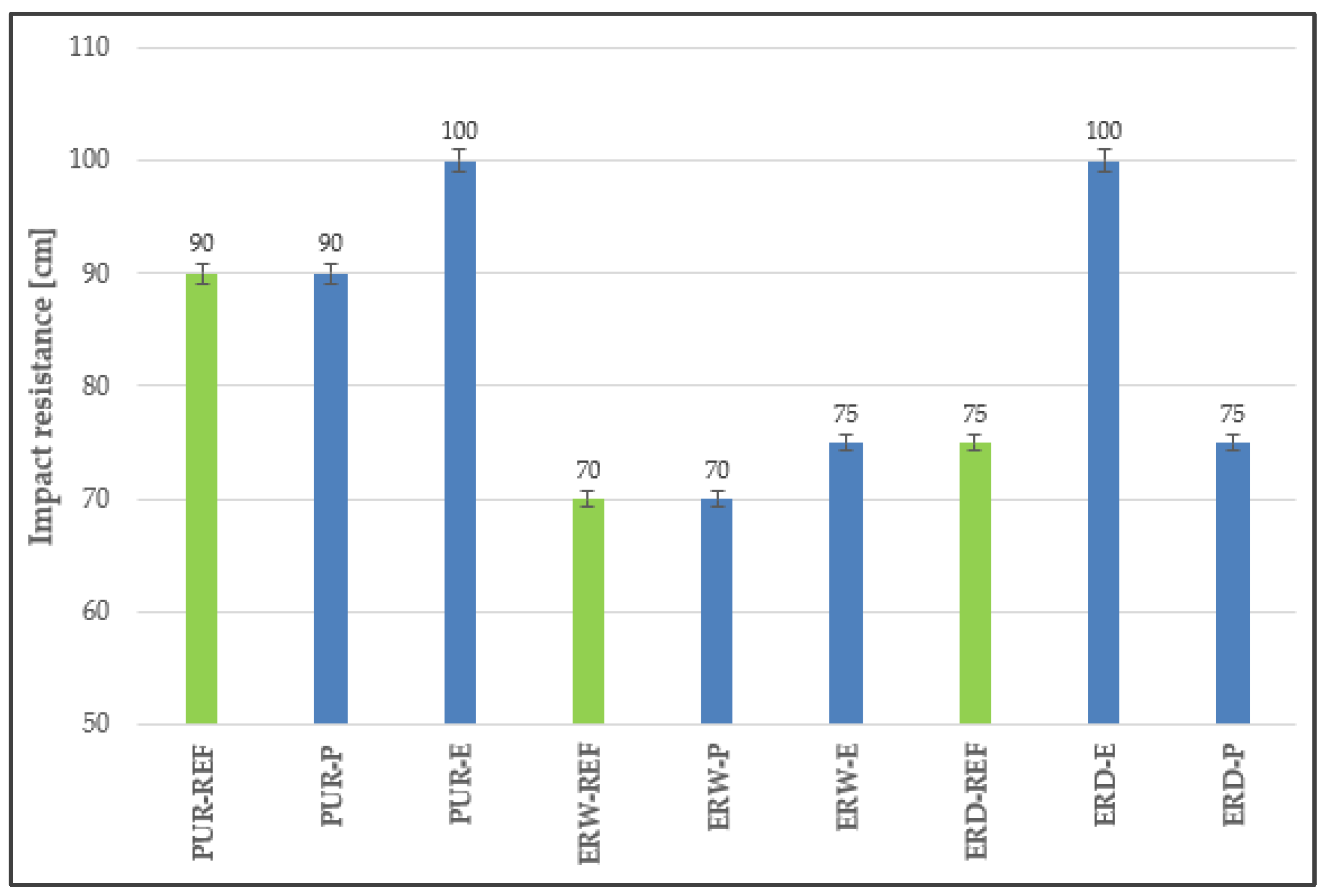
4.5. Impact Resistance
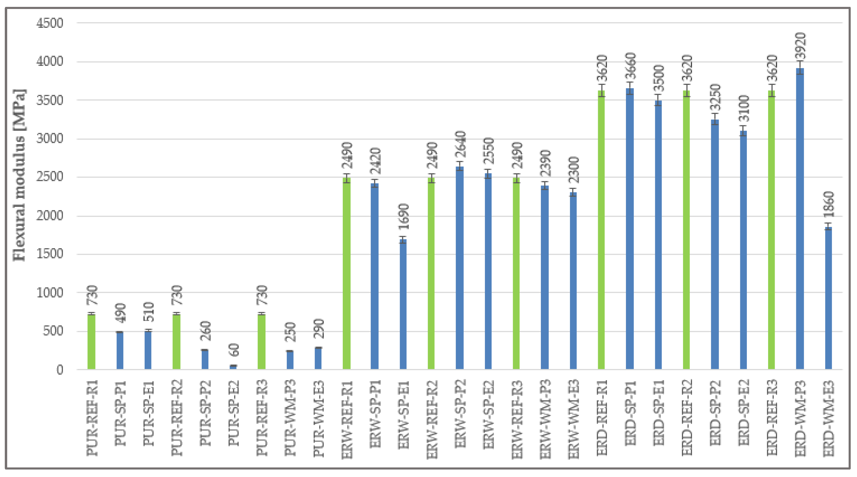
4.6. Flexural Modulus
4.7. Abrasion Resistance
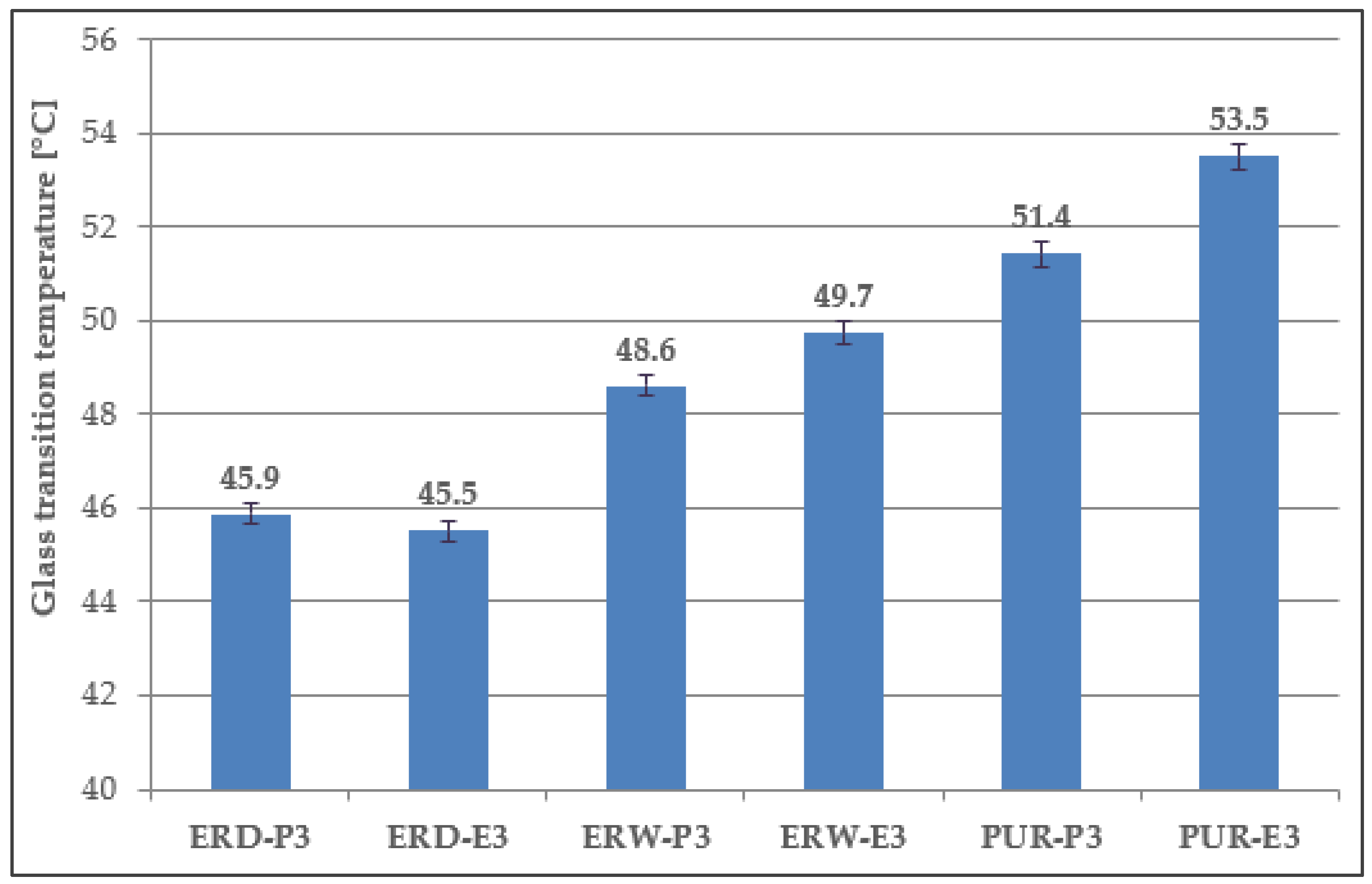
4.8. Determination of Tg
4.9. Chemical Resistance
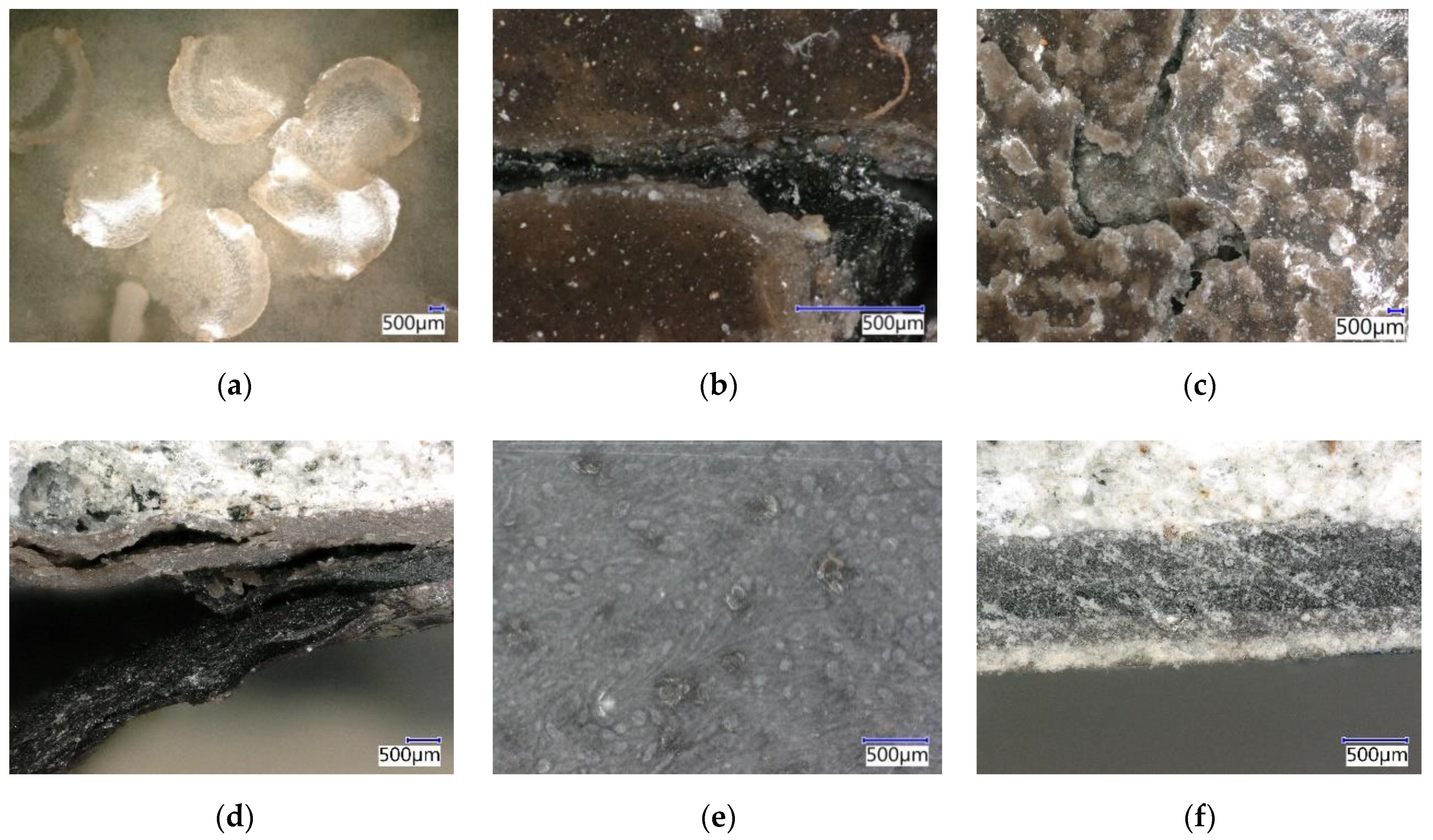
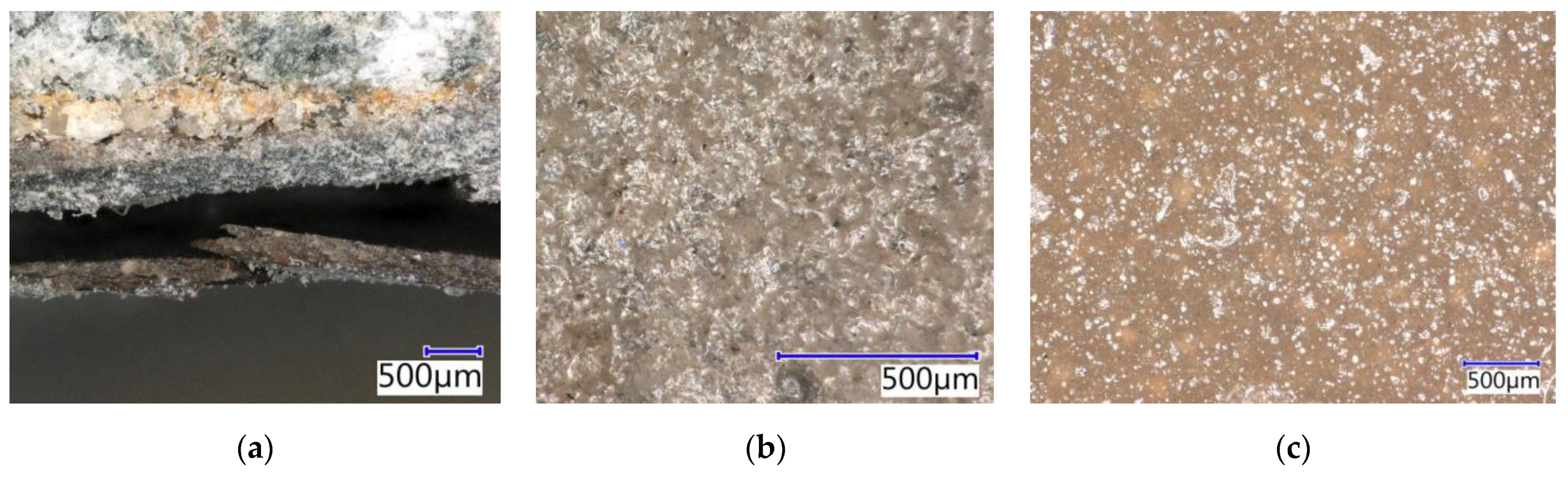
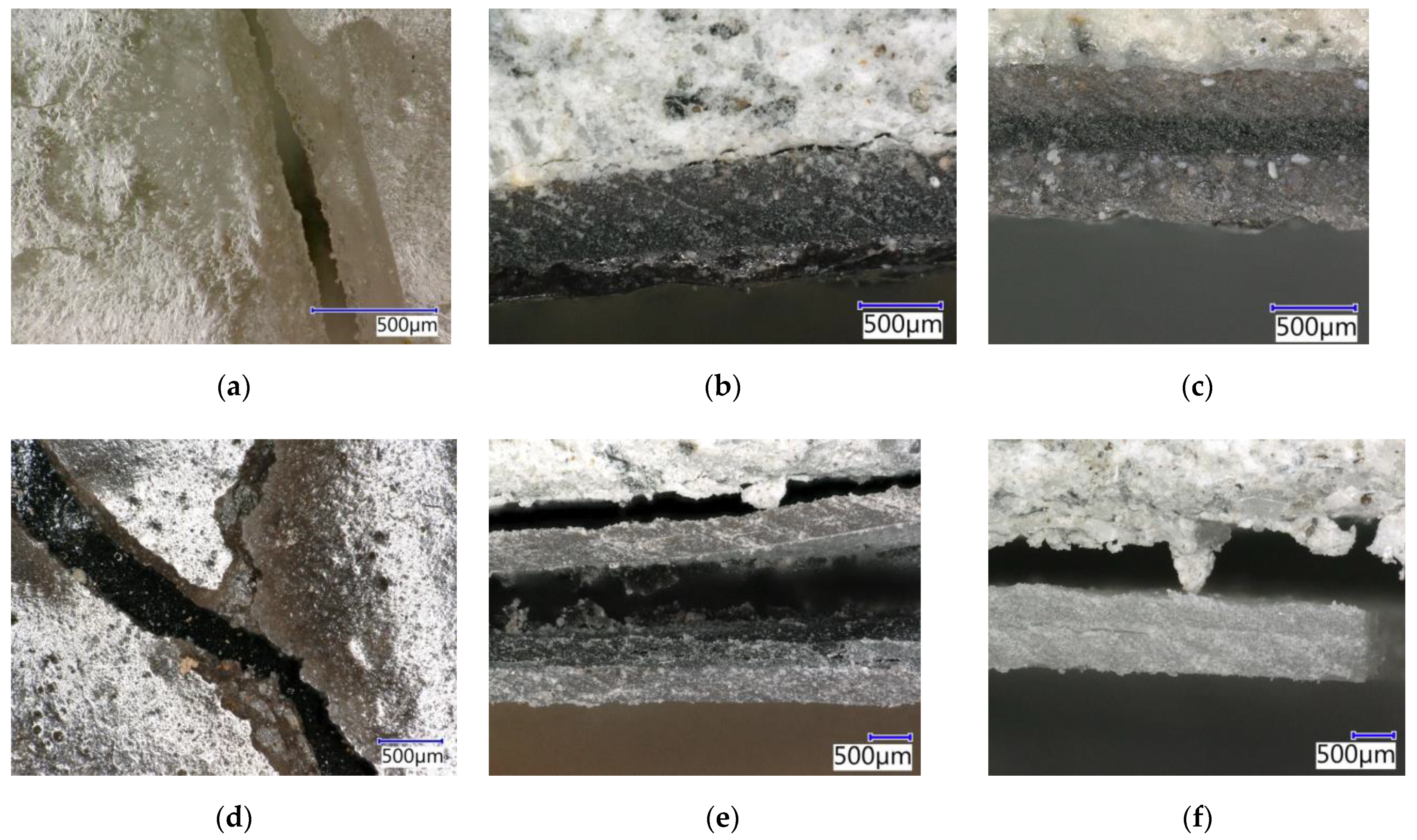
4.9.1. Evaluation by Digital Optical Microscopy
4.9.2. Hardness after Chemical Stress
4.9.3. Adhesion to Concrete after Chemical Stress
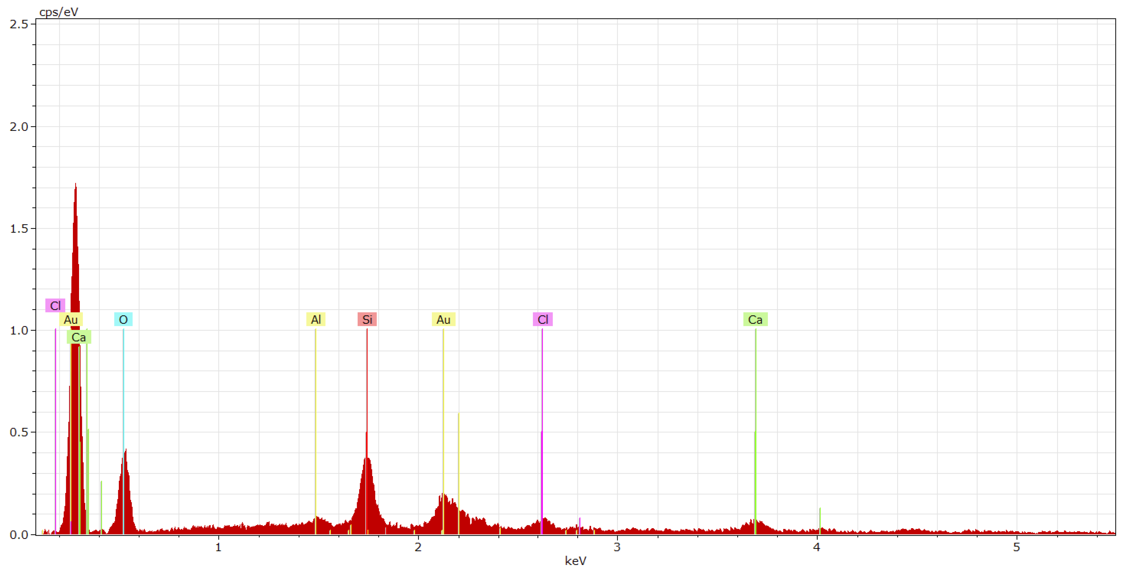
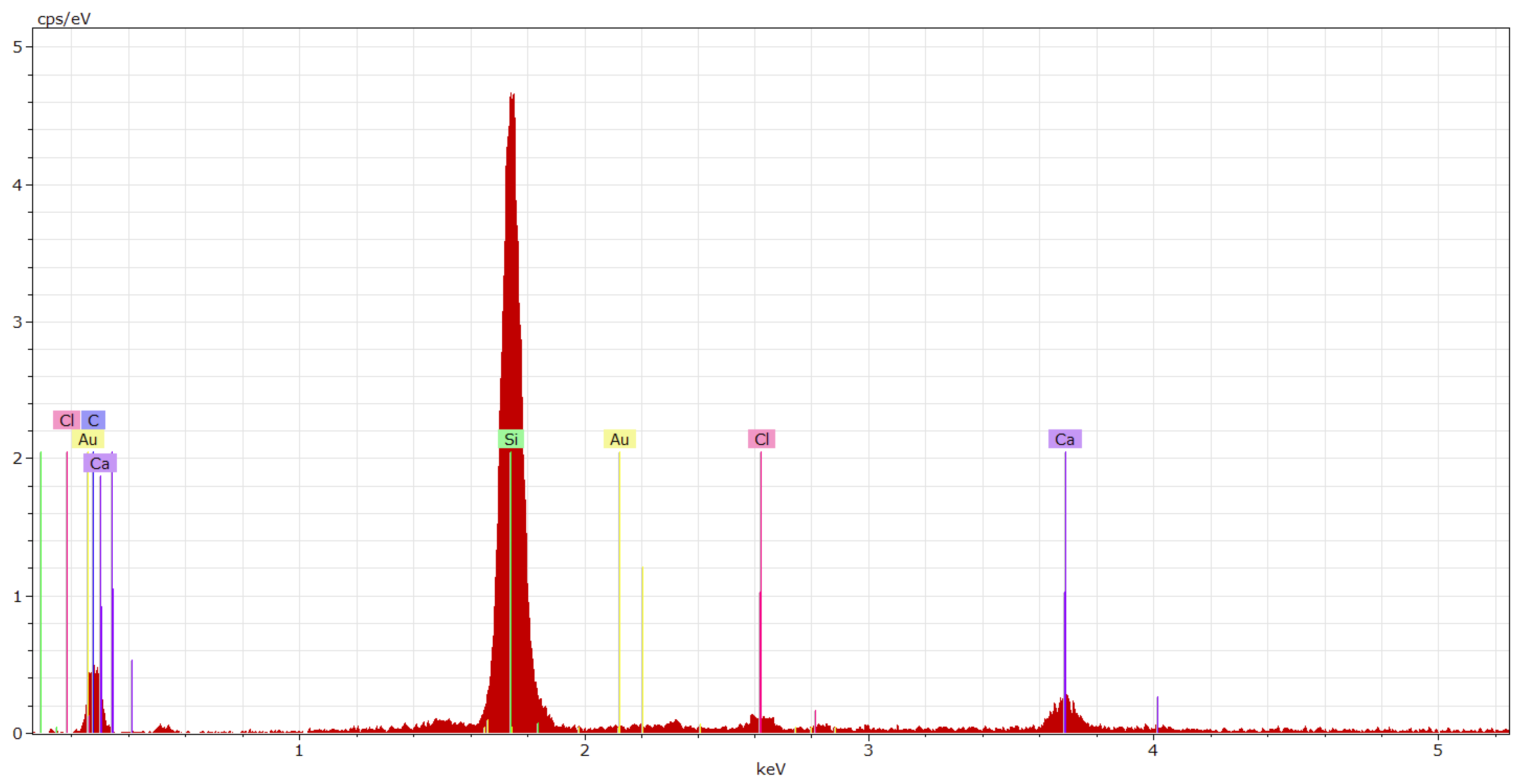
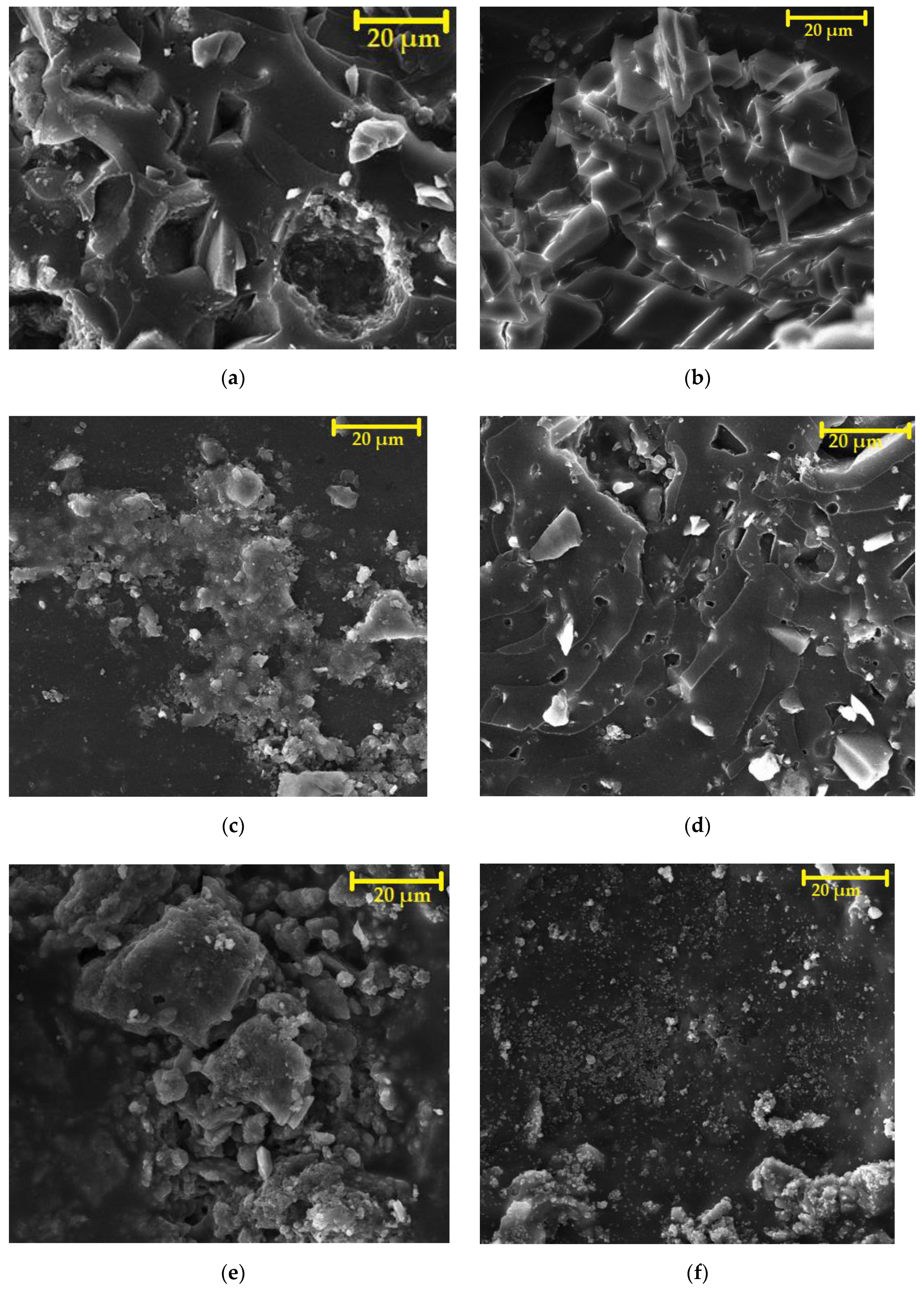
4.9.4. Microstructure after Chemical Stress by Using SEM
5. Conclusions
Author Contributions
Funding
Institutional Review Board Statement
Informed Consent Statement
Data Availability Statement
Conflicts of Interest
References
- Zhang, R.; Mallon, P.E.; Chen, H.; Huang, C.M.; Zhang, J.; Li, Y.; Jean, Y.C. Characterization of photodegradation of a polyurethane coating by positron annihilation spectroscopy: Correlation with cross-link density. Prog. Org. Coat. 2001, 42, 244–252. [Google Scholar] [CrossRef]
- Clough, R.L.; Billingham, N.C.; Gillen, K.T. (Eds.) Polymer Durability: Degradation, Stabilization, and Lifetime Prediction, Ser. No. 249; American Chemical Society: Washington, DC, USA, 1996. [Google Scholar]
- Sadowski, Ł.; Kampa, Ł.; Chowaniec, A.; Królicka, A.; Żak, A.; Abdoulpour, H.; Vantadori, S. Enhanced adhesive performance of epoxy resin coating by a novel bonding agent. Constr. Build. Mater. 2021, 301, 124078. [Google Scholar] [CrossRef]
- Almusallam, A.A.; Khan, F.M.; Dulaijan, S.U.; Al-Amoudi, O.S.B. Effectiveness of surface coatings in improving concrete durability. Cem. Concr. Compos. 2003, 25, 473–481. [Google Scholar] [CrossRef]
- Makki, H.; Adema, K.N.S.; Peters, E.A.J.F.; Laven, J.; van der Ven, L.G.J.; van Benthem, R.A.T.M.; de With, G. A simulation approach to study photo-degradation processes of polymeric coatings. Polym. Degrd. Stab. 2014, 105, 68–79. [Google Scholar] [CrossRef]
- Ahmetli, G.; Deveci, H.; Soydal, U.; Seker, A.; Kurbanli, R. Coating, mechanical and thermal properties of epoxy toluene oligomer modified epoxy resin/sepiolite composites. Prog. Org. Coat. 2012, 75, 97–105. [Google Scholar] [CrossRef]
- Chowaniec, A.; Sadowski, Ł.; Żak, A. The chemical and microstructural analysis of the adhesive properties of epoxy resin coatings modified using waste glass powder. Appl. Surf. Sci. 2020, 504, 144373. [Google Scholar] [CrossRef]
- Atta, A.M.; Abdou, M.I.; Elsayed, A.A.; Ragab, M.E. New bisphenol novolac epoxy resins for marine primer steel coating applications. Prog. Org. Coat. 2008, 63, 372–376. [Google Scholar] [CrossRef]
- Liu, M.; Mao, X.; Zhu, H.; Lin, A.; Wang, D. Water and corrosion resistance of epoxy-acrylic-amine waterborne coatings: Effects of resin molecular weight, polar group and hydrophobic segment. Corros. Sci. 2013, 75, 106–113. [Google Scholar] [CrossRef]
- Li, L.; Yu, Y.; Wu, Q.; Zhan, G.; Li, S. Effect of chemical structure on the water sorption of amine-cured epoxy resins. Corros. Sci. 2009, 51, 3000–3006. [Google Scholar] [CrossRef]
- Chen, P.; Wang, Y.; Li, J.; Wang, H.; Zhang, L. Adhesion and erosion properties of epoxy resin composite coatings reinforced with fly ash cenospheres and short glass fibers. Prog. Org. Coat. 2018, 125, 489–499. [Google Scholar] [CrossRef]
- Dulaijan, S.U.; Maslehuddin, M.; Al-Zahrani, M.M.; Al-Juraifani, E.A.; Alidi, S.A.; Al-Meththel, M. Performance evaluation of cement- based surface coatings. In Proceedings of the 2000 International Conference, Repair, Rehabilitation and Maintenance of Concrete Structures and Innovations in Design and Construction, Seoul, Korea, 19–22 September 2000; pp. 321–328. [Google Scholar]
- Santos, J.C.; Vieira, L.M.G.; Panzera, T.H.; Schiavon, M.A.; Christoforo, A.L.; Scarpa, F. Hybrid glass fibre reinforced composites with micro and poly-diallyldimethylammonium chloride (PDDA) functionalized nano silica inclusions. Mater. Des. 2015, 65, 543–549. [Google Scholar] [CrossRef]
- Kasaeian, M.; Ghasemi, E.; Ramezanzadeh, B.; Mahdavian, M.; Bahlakeh, G. Construction of a highly effective self-repair corrosion-resistant epoxy composite through impregnation of 1H-Benzimidazole corrosion inhibitor modified graphene oxide nanosheets (GO-BIM). Corros. Sci. 2018, 145, 119–134. [Google Scholar] [CrossRef]
- Heydarpour, M.R.; Zarrabi, A.; Attar, M.M.; Ramezanzadeh, B. Studying the corrosion protection properties of an epoxy coating containing different mixtures of strontium aluminum polyphosphate (SAPP) and zinc aluminum phosphate (ZPA) pigments. Prog. Org. Coat. 2014, 77, 160–167. [Google Scholar] [CrossRef]
- Ruiz, M.M.; Cavaillé, J.Y.; Dufresne, A.; Graillat, C.; Gérard, J. New waterborne epoxy coatings based on cellulose nanofillers. Macromol. Symp. 2001, 169, 211–222. [Google Scholar] [CrossRef]
- Noreen, A.; Zia, K.M.; Zuber, M.; Tabasum, S.; Saif, M.J. Recent trends in environmentally friendly water-borne polyurethane coatings: A review. Korean. J. Chem. Eng. 2016, 33, 388–400. [Google Scholar] [CrossRef]
- Wegmann, A. Chemical resistance of waterborne epoxy/amine coatings. Prog. Org. Coat. 1997, 32, 231–239. [Google Scholar] [CrossRef]
- Atta, A.M.; Shaker, N.O.; Nasser, N.E. Synthesis of bisphenol a novolac epoxy resins for coating applications. J. Appl. Polym. Sci. 2007, 107, 347–354. [Google Scholar] [CrossRef]
- Li, J.; Cui, J.; Yang, J.; Li, Y.; Qiu, H.; Yang, J. Reinforcement of graphene and its derivatives on the anticorrosive properties of waterborne polyurethane coatings. Compos. Sci. Technol. 2016, 129, 30–37. [Google Scholar] [CrossRef]
- Andersson, C. New ways to enhance the functionality of paperboard by surface treatment–a review. Packag. Technol. Sci. 2008, 21, 339–373. [Google Scholar] [CrossRef]
- Manigandan, S.; Praveenkumar, T.R.; Al-Mohaimeed, A.M.; Brindhadevi, K.; Pugazhendhi, A. Characterization of polyurethane coating on high performance concrete reinforced with chemically treated Ananas erectifolius fiber. Prog. Org. Coat. 2021, 150, 105977. [Google Scholar]
- Boisaubert, P.; Kébir, N.; Schuller, A.S.; Burel, F. Photo-crosslinked coatings from an acrylate terminated non-isocyanate polyurethane (NIPU) and reactive diluent. Eur. Polym. J. 2020, 138, 109961. [Google Scholar]
- Tao, Y.; Sun, G.; Wei, Y.; Liu, R.; Zhao, J. An anti-shrinkage model of an ultraviolet-curing coating filled with hollow polyurethane acrylate microspheres. Mech. Mater. 2021, 163, 104091. [Google Scholar] [CrossRef]
- Mohanty, S.R.; Mohanty, S.; Nayak, S.K. Synthesis and evaluation of novel acrylic and ester-based polyols for transparent polyurethane coating applications. Mater. Today Commun. 2021, 27, 102228. [Google Scholar] [CrossRef]
- Wang, H.; Xu, J.; Du, X.; Du, Z.; Cheng, X.; Wang, H. A self-healing polyurethane-based composite coating with high strength and anti-corrosion properties for metal protection. Compos. B Eng. 2021, 225, 109273. [Google Scholar] [CrossRef]
- Yang, H.; Zhang, M.; Chen, R.; Liu, Q.; Liu, J.; Yu, J.; Zhang, H.; Liu, P.; Lin, C.; Wang, J. Polyurethane coating with heterogeneity structure induced by microphase separation: A new combination of antifouling and cavitation erosion resistance. Prog. Org. Coat. 2021, 151, 106032. [Google Scholar] [CrossRef]
- Qian, Y.; Dong, F.; Guo, L.; Xu, X.; Liu, H. Two-component waterborne polyurethane modified with terpene derivative-based polysiloxane for coatings via a thiol-ene click reaction. Ind. Crops. Prod. 2021, 171, 113903. [Google Scholar] [CrossRef]
- Lopez, A.; Degrandi-Contraires, E.; Canetta, E.; Creton, C.; Keddie, J.L.; Asua, J.M. Waterborne polyurethane-acrylic hybrid nanoparticles by miniemulsion polymerization: Applications in pressure-sensitive adhesives. Langmuir 2011, 27, 3878–3888. [Google Scholar] [CrossRef] [Green Version]
- Chowaniec, A.; Czarnecki, S.; Sadowski, Ł. The effect of the amount and particle size of the waste quartz powder on the adhesive properties of epoxy resin coatings. Int. J. Adhes. Adhes. 2021, 103009. [Google Scholar]
- Yogeshwaran, S.; Natrayan, L.; Udhayakumar, G.; Godwin, G.; Yuvaraj, L. Effect of waste tyre particles reinforcement on mechanical properties of jute and abaca fiber-epoxy hybrid composites with pre-treatment. Mater. Today Proc. 2021, 37, 1377–1380. [Google Scholar] [CrossRef]
- Sharma, V.; Meena, M.L.; Kumar, M.; Patnaik, A. Optimization of waste fly ash powder filled glass fiber reinforced epoxy composite by hybrid AHP-TOPSIS approach. Mater. Today Proc. 2021, 44, 4789–4794. [Google Scholar] [CrossRef]
- Borsaikia, A.C.; Kumar, A.; Raj, A.; Dixit, U.S. Development of epoxy based composites using bamboo and waste metal chips. Encycl. Renew. Sustain. Mater. 2020, 1, 181–195. [Google Scholar]
- Dalhat, M.A. Utilization of date pits waste as aggregate alternative in sand-epoxy-resin composite. Constr. Build. Mater. 2020, 236, 117585. [Google Scholar] [CrossRef]
- Sevinç, A.H.; Durgun, M.Y. A novel epoxy-based composite with eggshell, PVC sawdust, wood sawdust and vermiculite: An investigation on radiation absorption and various engineering properties. Constr. Build. Mater. 2021, 300, 123985. [Google Scholar] [CrossRef]
- Hegde, S.; Padmaraj, N.H.; Siddesh, V.; Sunaya, T.S.; Adithya Kini, K.; Sanil, V.K. Experimental investigation of mechanical sustainability and acoustic performance of fly ash cenosphere/epoxy polymer composites. J. King Saud. Univ. Eng. Sci. 2021, in press. [Google Scholar] [CrossRef]
- Gobetti, A.; Cornacchia, G.; Ramorino, G.; Riboldi, A.; Depero, L.E. EAF slag as alternative filler for epoxy screeds, an example of green reuse. Sustain. Mater. Technol. 2021, 29, e00324. [Google Scholar] [CrossRef]
- Dębska, B.; Lichołai, L.; Silva, G.J.B. Effects of waste glass as aggregate on the properties of resin composites. Constr. Build. Mater. 2020, 258, 119632. [Google Scholar] [CrossRef]
- Revelo, C.F.; Correa, M.; Aguilar, C.; Colorado, H.A. Composite materials made of waste tires and polyurethane resin: A case study of flexible tiles successfully applied in industry. Case Stud. Constr. Mater. 2021, 15, e00681. [Google Scholar] [CrossRef]
- Olcay, H.; Kocak, E.D. Rice plant waste reinforced polyurethane composites for use as the acoustic absorption material. Appl. Acoust. 2021, 173, 107733. [Google Scholar] [CrossRef]
- Kuźnia, M.; Magiera, A.; Pielichowska, K.; Ziąbka, M.; Benko, A.; Szatkowski, P.; Jerzak, W. Fluidized bed combustion fly ash as filler in composite polyurethane materials. Waste Manag. 2019, 92, 115–123. [Google Scholar] [CrossRef]
- ISO 2884-2:2003; Paints and Varnishes—Determination of Viscosity Using Rotary Viscometers—Part 2: Disc or Ball Viscometer Operated at a Specified Speed. International Organization for Standardization (ISO) Technical Committee ISO/TC35/SC9: Geneva, Switzerland, 2003.
- ISO 868:2003; Plastics and Ebonite—Determination of Indentation Hardness by Means of a Durometer (Shore Hardness). International Organization for Standardization (ISO) Technical Committee ISO/TC61/SC2: Geneva, Switzerland, 2003.
- ISO 527-1:2019; Plastics—Determination of Tensile Properties—Part 1: General Principles. International Organization for Standardization (ISO) Technical Committee ISO/TC61/SC2: Geneva, Switzerland, 2019.
- ISO 527-2:2012; Plastics—Determination of Tensile Properties—Part 2: Test Conditions for Moulding and Extrusion, Plastics. International Organization for Standardization (ISO) Technical Committee ISO/TC61/SC2: Geneva, Switzerland, 2012.
- ISO 4624:2016; Paints and Varnishes—Pull-Off Test for Adhesion. International Organization for Standardization (ISO) Technical Committee ISO/TC35/SC9: Geneva, Switzerland, 2016.
- ISO 6272-1:2011; Paints and Varnishes—Rapid-Deformation (Impact Resistance) Tests—Part 1: Falling-Weight Test, Large-Area Indenter. International Organization for Standardization (ISO) Technical Committee ISO/TC35/SC9: Geneva, Switzerland, 2011.
- ISO 178:2019; Plastics—Determination of Flexural Properties. International Organization for Standardization (ISO) Technical Committee ISO/TC61/SC2: Geneva, Switzerland, 2019.
- CEN. EN 13892-3—Methods of Test for Screed Materials—Part 3: Determination of Wear Resistance—Böhme; European Committee for Standardization (CEN): Brussels, Belgium, 2014. [Google Scholar]
- Memon, H.; De Focatiis, D.S.A.; Choi, K.S.; Hou, X. Durability enhancement of low ice adhesion polymeric coatings. Prog. Org. Coat. 2021, 151, 106033. [Google Scholar] [CrossRef]
- Krzywiński, K.; Sadowski, Ł.; Stefaniuk, D.; Obrosov, A.; Weiß, S. Engineering and manufacturing technology of green epoxy resin coatings modified with recycled fine aggregates. Int. J. Precis. Eng. Manuf. Green Technol. 2021, 9, 253–271. [Google Scholar] [CrossRef]
- Awaja, F.; Gilbert, M.; Kelly, G.; Fox, B.; Pigram, P.J. Adhesion in polymer science. Prog. Polym. Sci. 2009, 34, 948–968. [Google Scholar] [CrossRef]
- Momber, A.W.; Irmer, M.; Marquardt, T. Effects of polymer hardness on the abrasive wear resistance of thick organic offshore coatings. Prog. Org. Coat. 2020, 146, 105720. [Google Scholar] [CrossRef]
- Malaki, M.; Hashemzadeh, Y.; Tehrani, A.F. Abrasion resistance of acrylic polyurethane coatings reinforced by nano-silica. Prog. Org. Coat. 2018, 125, 507–515. [Google Scholar] [CrossRef]
- Barbakadze, K.; Brostow, W.; Datashvili, T.; Hnatchuk, N.; Lekishvili, N. Antibiocorrosive epoxy-based coatings with low friction and high scratch resistance. Wear 2018, 394, 228–235. [Google Scholar] [CrossRef]
- Yeasmin, F.; Mallik, A.K.; Chisty, A.H.; Robel, F.N.; Shahruzzaman, M.; Haque, P.; Rahman, M.M.; Hano, N.; Takafuji, M.; Ihara, H. Remarkable enhancement of thermal stability of epoxy resin through the incorporation of mesoporous silica micro-filler. Heliyon 2021, 7, E05959. [Google Scholar] [CrossRef]
- da Silva, L.R.R.; Avelino, F.; Diogenes, O.B.F.; Sales, V.O.F.; da Silva, K.T.; Araujo, W.S.; Mazzeto, S.E.; Lomonaco, D. Development of BPA-free anticorrosive epoxy coatings from agroindustrial waste. Prog. Org. Coat. 2020, 139, 105449. [Google Scholar] [CrossRef]
- Sabu, T.; Sinturel, C.; Raju, T. Micro and Nanostructured Epoxy/Rubber Blends. In Properties of Materials; Wiley-Vch: Hoboken, NJ, USA, 2014; p. 464. [Google Scholar]


| Coating System | Filler | Cement Bypass Dust 1 | End Product 1 | FC | FF | Silica Flour |
|---|---|---|---|---|---|---|
| CS-E | SP-E1 | 10 | - | 90 | - | - |
| SP-E2 | 5 | - | - | 95 | - | |
| WM-E3 | - | - | 100 | - | - | |
| CS-P | SP-P1 | - | 10 | 40 | - | 50 |
| SP-P2 | - | 5 | - | 35 | 60 | |
| SP-E1 | - | - | 40 | - | 60 |
| Binder | Component A | Component B |
|---|---|---|
| Solvent-free epoxy resin (ERD) | Epoxy resin with average molecular weight ≤ 700 | Formaldehyde |
| (Alkoxymethyl) oxirane (alkyl C12-C14) formaldehyde | Polymer with N’-(3-aminopropyl)propane-1,3-diamine | |
| Oligomeric reaction products with 1-chloro-2,3-epoxypropane and phenol | polyamine adduct, carbomonocyclic alkylated mixtures of poly-aza-alkanes, hydrogenated | |
| Water-soluble epoxy resin (ERW) | Epoxy resin with average molecular weight ≤ 700 | fatty acids, tall oil, reaction product with tetraethylenetriamine |
| (Alkoxymethyl) oxiran (alkyl C12-C14) formaldehyde | 4,4-Isopropylidenediphenol, 3-Aminopropyldimethylamine | |
| Oligomeric reaction products with 1-chloro-2,3-epoxypropane and phenol | 2,4,6-Tris(dimethylaminomethyl)phenol, 1,3-bis(aminomethyl)benzene | |
| Polyurethane resin (PUR) | Fumaric acid diethyl ester | Hexamethylene diisocyanate |
| oligomers |
| Type of Coating System | Layer | Polymer Binder | Filler | Filler Content [wt%] |
|---|---|---|---|---|
| CS-E | 1 | ERD | SP-E1 | 20 |
| 2 | ERD | SP-E2 | 30 | |
| 3 | ERD | WM-E3 | 30 | |
| CS-P | 1 | ERD | SP-P1 | 20 |
| 2 | ERD | SP-P2 | 30 | |
| 3 | ERD | WM-P3 | 30 |
| Type of Coating System | Layer | Polymer Binder | Filler | Filler Content [wt%] |
|---|---|---|---|---|
| CS-E | 1 | ERW | SP-E1 | 30 |
| 2 | ERW | SP-E2 | 30 | |
| 3 | ERW | WM-E3 | 30 | |
| CS-P | 1 | ERW | SP-P1 | 30 |
| 2 | ERW | SP-P2 | 30 | |
| 3 | ERW | WM-P3 | 30 |
| Type of Coating System | Layer | Polymer Binder | Filler | Filler Content [wt%] |
|---|---|---|---|---|
| CS-E | 1 | PUR | SP-E1 | 20 |
| 2 | PUR | SP-E2 | 20 | |
| 3 | PUR | WM-E3 | 20 | |
| CS-P | 1 | PUR | SP-P1 | 20 |
| 2 | PUR | SP-P2 | 20 | |
| 3 | PUR | WM-P3 | 20 |
| Coating System | Solution | Adhesion [MPa] | Reduction in Adhesion [%] | Place of Failure |
|---|---|---|---|---|
| ERD-P | 30% HCl | 3.71 | 42.2 | glue |
| 30% H2SO4 | 3.57 | 44.4 | glue | |
| xylene | 4.01 | 37.5 | concrete | |
| ERD-E | xylene | 4.01 | 37.5 | concrete |
| 30% HCl | 4.15 | 1.0 | glue | |
| 30% H2SO4 | 4.00 | 1.23 | glue | |
| xylene | 2.37 | 41.5 | glue | |
| ERD-REF | 30% HCl | 1.04 | 72.5 | glue |
| 10% HCOOH | 0.57 | 86.8 | glue | |
| ERW-P | 30% HCl | 3.16 | 42.3 | glue |
| ERW-E | 30% HCl | 3.01 | 35.1 | glue |
| PUR-P | 30% HCl | 3.68 | 1.0 | concrete |
| 30% H2SO4 | 2.07 | 27.9 | glue | |
| 10% HCOOH | 2.68 | 6.6 | concrete | |
| PUR-E | 30% HCl | 1.78 | 52.4 | glue |
| 10% HCOOH | 3.48 | 6.6 | concrete | |
| PUR-REF | 30% HCl | 0.12 | 96.3 | concrete |
| 30% H2SO4 | 3.07 | 4.4 | concrete | |
| 10% HCOOH | 3.01 | 6.2 | glue |
Publisher’s Note: MDPI stays neutral with regard to jurisdictional claims in published maps and institutional affiliations. |
© 2022 by the authors. Licensee MDPI, Basel, Switzerland. This article is an open access article distributed under the terms and conditions of the Creative Commons Attribution (CC BY) license (https://creativecommons.org/licenses/by/4.0/).
Share and Cite
Hodul, J.; Mészárosová, L.; Drochytka, R. New Chemically Resistant Coating Systems with Progressive Incorporation of Hazardous Waste in Polyurethane and Epoxy Matrices. Materials 2022, 15, 3235. https://doi.org/10.3390/ma15093235
Hodul J, Mészárosová L, Drochytka R. New Chemically Resistant Coating Systems with Progressive Incorporation of Hazardous Waste in Polyurethane and Epoxy Matrices. Materials. 2022; 15(9):3235. https://doi.org/10.3390/ma15093235
Chicago/Turabian StyleHodul, Jakub, Lenka Mészárosová, and Rostislav Drochytka. 2022. "New Chemically Resistant Coating Systems with Progressive Incorporation of Hazardous Waste in Polyurethane and Epoxy Matrices" Materials 15, no. 9: 3235. https://doi.org/10.3390/ma15093235
APA StyleHodul, J., Mészárosová, L., & Drochytka, R. (2022). New Chemically Resistant Coating Systems with Progressive Incorporation of Hazardous Waste in Polyurethane and Epoxy Matrices. Materials, 15(9), 3235. https://doi.org/10.3390/ma15093235