
A Special Ancient Bronze Sword and Its Possible Manufacturing Technique from Materials Science Analysis


Abstract
:1. Introduction
2. Materials and Experimental Methods
3. Experimental Results
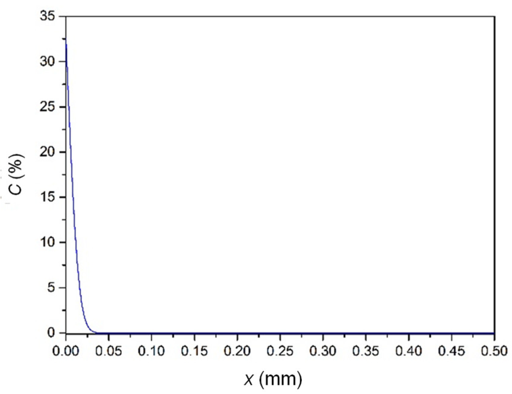
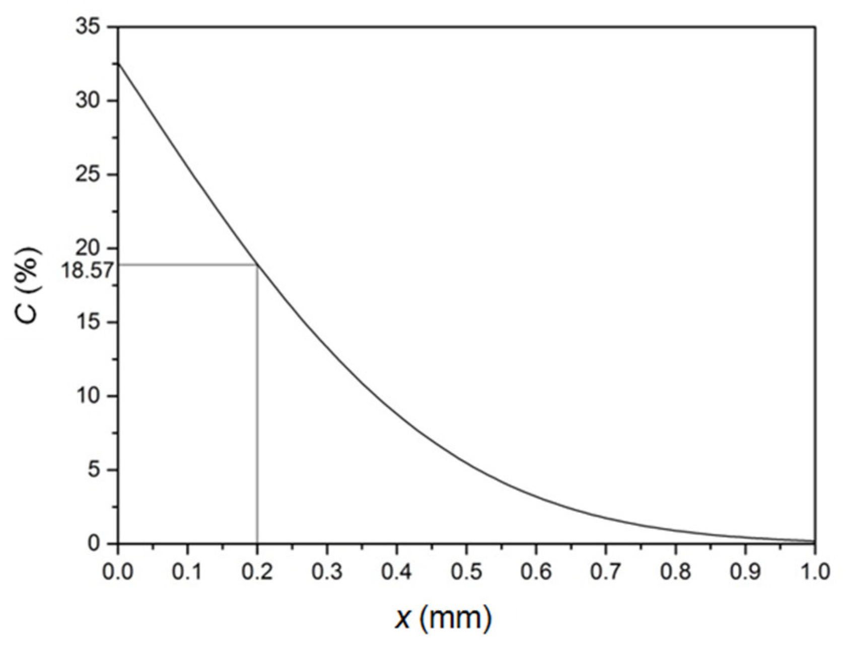
4. Simulation Calculations of Sn Element Diffusion in Bronze
4.1. The Basic Law of Element Diffusion
4.2. Calculation of Sn Diffusion in Bronze
5. Discussion
6. Conclusions
Author Contributions
Funding
Institutional Review Board Statement
Informed Consent Statement
Data Availability Statement
Conflicts of Interest
References
- Xiao, M.L. A study of bronze weapons of the Wu State. Acta Archaeol. Sin. (Kaogu Xuebao) 1991, 2, 141–165. (In Chinese) [Google Scholar]
- Xiao, M.L. The discussion on bronze weapons of Wu State and Yue State. Archaeol. Cult. Relics (Kaogu Yu Wenwu) 1996, 6, 16–28. (In Chinese) [Google Scholar]
- Lian, H.P.; Tan, D.R. Study on bimetallic bronze swords in ancient China. Sci. Conserv. Archaeol. 2002, 14, 319–334. (In Chinese) [Google Scholar]
- Ding, Z.M.; Qu, C.G.; Liu, Y.C.; Wu, L.M.; Mu, H.M. Studies on the manufacturing techniques of bimetallic bronze swords in the Eastern Zhou period excavated from Xintai, Shandong. Sci. Conserv. Archaeol. 2012, 24, 75–86. (In Chinese) [Google Scholar]
- Gao, S.L.; Zhang, T.X.; Fan, J.H. Casting Technology of Bronze Sword in Ancient China. Foundry Technol. 2018, 39, 808–811. (In Chinese) [Google Scholar]
- Li, B.; Jiang, X.; Tu, Y.; Lv, J.; Fu, Q.; Wei, B.; Hu, T.; Pan, C. Study on Manufacturing Process of Ancient Chinese Bi-metallic Bronze Ge. Archaeol. Anthropol. Sci. 2020, 12, 62–71. [Google Scholar] [CrossRef]
- Li, Y.; Wu, T.; Liao, L.; Liao, C.; Zhang, L.; Chen, G.; Pan, C. Techniques employed in making ancient thin-walled bronze vessels unearthed in Hubei Province, China. Appl. Phys. A 2013, 111, 913–922. [Google Scholar] [CrossRef]
- Meeks, N.D. Tin-rich surfaces on bronze–some experimental and archaeological considerations. Archaeometry 1986, 28, 133–162. [Google Scholar] [CrossRef]
- Callister, W.D.; Rethwisch, D.G. Materials Science and Engineering: An Introduction, 7th ed.; Wiley: New York, NY, USA, 2007. [Google Scholar]
- Brandes, E.A.; Brook, G.B. Smithells Metal Reference Book, 7th ed.; Butterworth-Heinemann: Oxford, UK, 1992; Chapter 13. [Google Scholar]
- Fujiwara, Y. Sn deposition onto Cu and alloy layer growth by a contact immersion. Thin Solid Films 2003, 425, 121–126. [Google Scholar] [CrossRef]
- He, K.; Li, Y.; Pan, C. Material characteristics of tin-rich surface layer on Warring States bronze swords unearthed in Hubei. Mater. Prot. 2012, 45, 50–53. (In Chinese) [Google Scholar]
- Sun, S.Y.; Yao, Z.H.; Li, X.C.; Han, R.B. A study on tinning techniques on surfaces of Chinese bronzes. Sci. Conserv. Archaeol. 2008, 20, 42–52. (In Chinese) [Google Scholar]
- Ma, Q.L.; Su, B.M.; Hu, Z.D.; Li, Z.Z.; Chen, G.L. Evaluation of Tin Coatings on Bronzes of Ancient China. J. Lanzhou Univ. (Nat. Sci.) 1999, 35, 67–72. (In Chinese) [Google Scholar]
- Luo, M.; Li, Y.X.; Ma, Q.L. Engraving techniques used on the surfaces of tinned bronze belts during the Spring and Autumn and Warring States Period in Gansu Province. Sci. Conserv. Archaeol. 2019, 31, 65–74. (In Chinese) [Google Scholar]


| Element | Cu | Sn | Fe | Si | P |
|---|---|---|---|---|---|
| Sword body | 81.43 | 18.57 | — | — | — |
| Sn-Rich layer | 53.42 | 38.51 | 6.06 | 1.27 | 0.75 |
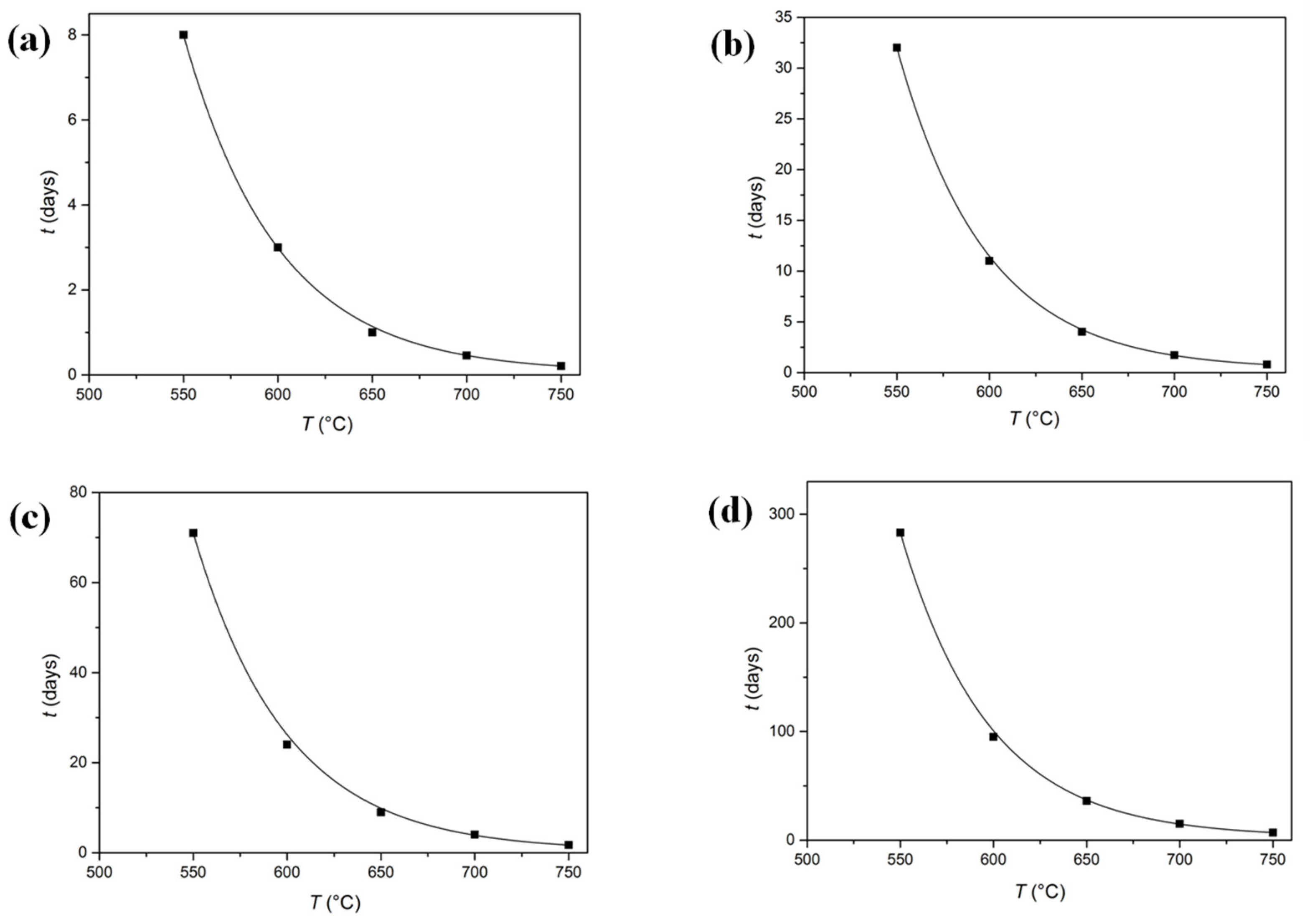
| Temperature (°C) | D (cm2/s) | Time (x = 0.1 mm) | Time (x = 0.2 mm) | Time (x = 0.3 mm) | Time (x = 0.6 mm) |
|---|---|---|---|---|---|
| 550 | 2.3 × 10⁻¹⁰ | 8 d | 32 d | 71 d | 283 d |
| 600 | 6.9 × 10⁻¹⁰ | 3 d | 11 d | 24 d | 95 d |
| 650 | 1.8 × 10⁻⁹ | 1 d | 4 d | 9 d | 36 d |
| 700 | 4.3 × 10⁻⁹ | 11 h | 41 h | 4 d | 15 d |
| 750 | 9.5 × 10⁻⁹ | 5 h | 19 h | 41 h | 7 d |
Publisher’s Note: MDPI stays neutral with regard to jurisdictional claims in published maps and institutional affiliations. |
© 2022 by the authors. Licensee MDPI, Basel, Switzerland. This article is an open access article distributed under the terms and conditions of the Creative Commons Attribution (CC BY) license (https://creativecommons.org/licenses/by/4.0/).
Share and Cite
Xie, C.; Fu, C.; Li, S.; Liao, L.; Chen, G.; Pan, C. A Special Ancient Bronze Sword and Its Possible Manufacturing Technique from Materials Science Analysis. Materials 2022, 15, 2491. https://doi.org/10.3390/ma15072491
Xie C, Fu C, Li S, Liao L, Chen G, Pan C. A Special Ancient Bronze Sword and Its Possible Manufacturing Technique from Materials Science Analysis. Materials. 2022; 15(7):2491. https://doi.org/10.3390/ma15072491
Chicago/Turabian StyleXie, Chi, Chunlin Fu, Sishi Li, Lingmin Liao, Guantao Chen, and Chunxu Pan. 2022. "A Special Ancient Bronze Sword and Its Possible Manufacturing Technique from Materials Science Analysis" Materials 15, no. 7: 2491. https://doi.org/10.3390/ma15072491
APA StyleXie, C., Fu, C., Li, S., Liao, L., Chen, G., & Pan, C. (2022). A Special Ancient Bronze Sword and Its Possible Manufacturing Technique from Materials Science Analysis. Materials, 15(7), 2491. https://doi.org/10.3390/ma15072491