Article

Characterization of Microstructure, Phase Composition, and Mechanical Behavior of Ballistic Steels

Materials and Surface Engineering Laboratory, Department of Metallurgical Engineering, NED University of Engineering and Technology, Karachi 75270, Pakistan
*
Author to whom correspondence should be addressed.
Materials 2022, 15(6), 2204; https://doi.org/10.3390/ma15062204
Submission received: 28 January 2022 / Revised: 1 March 2022 / Accepted: 7 March 2022 / Published: 16 March 2022

Abstract

:
For the protection of civil and military armored vehicles, advanced steels are used, due to their outstanding mechanical properties, high ballistic performance, ease of manufacturing and low cost. However, after retrofitting, weight is the prominent issue. In this regard, several strategies are being proposed, which include the surface engineering of either low-thickness ballistic steels or conventional steels, in addition to new alloys and composites. Therefore, to better understand the response of such materials under various stimuli, the existing state of the art ballistic steels was utilized in this study. The aim of this study was to better understand the existing materials and their corrosion behavior. Therefore, in this connection, two thicknesses were selected, i.e., thin (6.7–7.0 mm) and thick (13.0–15.0 mm), henceforth termed as low thickness (LT) and high thickness (HT), respectively. This was followed by characterization using tensile, Charpy, micro-Vickers, nanoindentation, XRD, SEM-EDS and corrosion tests. Microstructurally, the LT samples only exhibited ε-carbide precipitates, whereas the HT samples contained both ε-carbides and Mo2C (molybdenum carbides). However, both samples were found to be tempered martensite with a lath morphology. Moreover, higher hardness, and lower elastic modulus and stiffness were noticed in the HT samples compared with their LT counterparts. Fractured surfaces of both of these alloys were also examined, wherein a ductile mode of fracturing was observed. Further, a corrosion study was also carried out in brine solution. The results showed a higher corrosion rate in the HT samples than that of their LT counterparts. An extensive discussion is presented in light of the observed findings.

1. Introduction

Modern small range arms cause an extreme threat to both civilian and military vehicles and infrastructure worldwide. However, protective materials used in such vehicles play an important role in minimizing or preventing the associated threats. Thus, materials such as steels [1], composites and ceramics [2] have earned significant importance in providing the desired protection. The performance of materials is largely dependent on the processing, structure and property co-relationships. Among all metallic armor materials, high-strength ballistic steels are widely used to avert threats at different levels. In addition, they offer the combination of high strength, hardness and toughness, excellent ballistic performance, good machinability, ease of heat treatment and weldability [3].
Ballistic steels are made into slabs by the casting process, and then hot rolled into plates of the desired thicknesses. This is also known as rolled homogenous armor (RHA) steel [4]. Next, they are subjected to austenitizing, quenching and tempering processes to obtain the desired properties [5]. Thus, in the development of high-strength ballistic steel plates, alloying, rolling and heat treatment processes play a vital role [6,7]. Moreover, the ballistic performance of steels (e.g., 50Cr4V steel) depends on the hardness, toughness and strength. Thus, improvements in such properties will depend on the microstructure, e.g., tempered martensite, etc., in addition to other factors. This necessitates an optimal combination of strength, hardness and toughness [8,9,10,11]. Material properties versus projectile impact has been of practical significance for ballistic protection applications [12], in addition to the thickness of steel plates [13,14].
The microstructure of ballistic steels usually consists of martensite, bainite or tempered martensite, or a combination thereof [15]. Specifically, the martensitic phase provides high hardness and strength levels in steel. It should be noted that the strength and hardness are increased by the quenching process, whereas tempering increases the ductility and toughness in steels, thus enhancing the impact energy absorption capability [16,17,18].
Moreover, it is of paramount importance to predict the ballistic performance of steels, since mechanical properties alone do not suffice. Thus, the microstructural approach is equally important in this regard [19,20,21,22]. Processing parameters play an important role too, such as tempering temperature, etc. For example, it has been reported that the mechanical properties of high-strength ballistic steel are significantly enhanced at lower tempering temperatures [23]. Microstructurally, a combination of martensite and bainite phases is instrumental for the desired performance of steels [24]. In addition, even the morphologies of martensite must be examined, such as the butterfly, lath, lenticular and plate types, since such morphologies are responsible for the desired properties of steels. Lenticular martensite forms in steel with a high carbon content, whereas lath martensite forms in steel with a low carbon content [25]. Lath morphology in a tempered martensite structure increases the dynamic strength of steel [26]. Further studies on steels showed that alloying elements such as carbon, manganese, boron, nickel and molybdenum improves their mechanical characteristics [27], since alloyed elements are important constituents in the formation of various precipitates, such as carbides, that are beneficial for the strength of steels [28].
Moreover, corrosion resistance is another property that is as important as the desired protection. The literature suggests that martensite exhibits lower corrosion resistance than ferrite and other phases, since corrosion depends on the nature, size and distribution of phases in the microstructure [29,30].
Therefore, in the present study, ballistic steel plates of various thicknesses were studied to better understand their microstructure, mechanical properties and corrosion resistance, since, to the best of the authors’ knowledge, there are no corrosion studies that have been conducted on ballistic steels in brine solution. In addition, the focus of this study is on LT steels and how they differ from their HT counterparts. This is because the weight of the vehicle after armoring is an issue of concern, since suspension, transmission and other parts (of the vehicle) need improvement. This will facilitate the search for an alternative material with a similar microstructure to the HT counterpart.

2. Experimental Work

2.1. Materials

The main material for this study is the state-of-the-art ballistic steels (Pak Armoring & Streit Pakistan, Karachi, Pakistan), which are currently being used for both military and civilian vehicles. The steel plates were obtained from local markets, as shown in Table 1.
Moreover, the chemical composition and mechanical properties of standard material are shown in Table 2 and Table 3, respectively [31,32].

2.2. Methods

2.2.1. Metallography

The ballistic steel samples were cut into 15 mm × 15 mm squares using an abrasive cut-off machine (Metkon, Model: METACUT M-250, Bursa, Turkey), and cold mounted in epoxy resin (Allied High Tech Products Inc., Compton, CA, USA). This was followed by grinding progressively from 240 to 1200 grit silicon carbide papers. Thereafter, polishing was carried out with different sizes of diamond paste, i.e., 5 μm, 3 μm and 0.5 μm, using a polishing machine.

2.2.2. Etching

Samples were etched after polishing using 2% Nital (2 mL HNO3 and 98 mL methyl alcohol) (Sigma-Aldrich, St. Louis, MI, USA) at room temperature to reveal their microstructures.

2.3. Testing and Characterization

2.3.1. Optical Emission Spectroscopy (OES)

Samples were cut into 30 mm × 30 mm sizes using the abrasive cut-off machine to find out the chemical composition. Optical emission spectroscopy (Ametek, Model: SPECTROMAXx, Berwyn, PA, USA) was used to measure the chemical composition of samples.

2.3.2. Microscopy

The microstructures of the ballistic steel samples were obtained using an optical microscope (Metkon, IMM-901, Bursa, Turkey) and a scanning electron microscope (Tescan, Series: VEGA3, Brno, Czech Republic). For microstructural details, the scanning electron microscope was operated at 20 kV and at different magnifications. An energy-dispersive X-ray spectrometer (Brucker, Model: 1119-400, Billerica, MA, USA) was used with SEM for further chemical composition analysis of ballistic steels.

2.3.3. X-ray Diffraction

For X-ray diffraction (XRD) measurement, rectangular samples of 2 mm thickness with a dimension of 40 mm × 20 mm were cut from each of the plates using a wire cutting machine. The samples were ground from 320 to 1000 grit silicon carbide paper and then polished using 5 μm diamond paste. The samples were then ultrasonically cleaned in an ethanol bath. An X-ray diffractometer (PANalytical, Model: PW3040/60 X’Pert Pro, Amsterdam, The Netherlands) was used to analyze different phases in the samples. The X-ray diffractometer was run at a current of 30 mA and a voltage of 40 kV, and scanned over 1 h, at 2θ angles from 10 to 80° with a step of 0.025° and CuKα radiation, at room temperature. The acquired XRD peaks were examined by the comparison method with the help of the JCPDS data file 65-4899 [33].

2.3.4. Tensile Testing

Tensile testing procedures as well as the geometry of samples are prescribed in the ASTM E8 standard. The samples were run at a speed of 5 mm/min using a hydraulic universal testing machine (Daekyung Tech & Testers, Model: DTU-900HCB, Incheon, Korea) at room temperature, to determine their tensile properties. The yield strength of samples was determined at 0.2% strain using the offset method. Three samples from each steel plate were tensile tested and the average value for each steel plate was measured.

2.3.5. Charpy Impact Testing

For preparation of standard Charpy, V-notch samples were machined in a size of 10 mm × 10 mm × 55 mm for larger thickness plates and in a size of 5 mm × 10 mm × 55 mm (subsize sample) for smaller thickness plates, with a 2 mm depth notch, using the wire cutting machine as prescribed in the ASTM E23 standard. Impact testing of samples was carried out by using the pendulum impact testing machine (Wance, Model: 452G-3, Shenzhen, China). During impact testing, a hammer of 300 joules was used. Three samples from each steel plate were impact tested and the average value of each sample was measured.

2.3.6. Vickers Microhardness Testing

The samples for Vickers microhardness testing were prepared according to the methods defined in Section 2.2.1 and Section 2.2.2. The hardness of samples was determined as per ASTM E92 using Vickers microhardness tester (Shimadzu, Model: HMV-G31, Kyoto, Japan) under applied load of 500 g and holding time of 10 s. Ten indents were recorded at different locations and their average values are reported. The bulk hardness was determined.

2.3.7. Nanoindentation Testing

In addition to Vickers microhardness, nanoindentation testing was also carried out as per the procedure defined in Section 2.2.1 and Section 2.2.2. Nanoindentation of samples was performed according to ASTM E2546 using a nanoindenter (Anton Paar, Model: TTX-NHT3, Graz, Austria).
A diamond Berkovich indenter (Anton Paar, TTX-NHT3, Graz, Austria) was used by applying a load of 100 mN for a holding time of 15 s. A microscope at 1000× magnification was attached to the nanoindenter that was used to reveal various phases in the microstructures of samples. During the nanoindentation test, the loading and unloading rate was 200 mN/min. To determine the micro-mechanical properties, such as indentation hardness, elastic modulus and stiffness, an array of three nanoindentations were performed at different locations, and the average values were calculated using the Oliver–Pharr method [34]. To avoid possible effects of plastic zone overlapping in samples, spacing of 4 μm between the two indents was maintained [35].

2.3.8. Fractography

After mechanical testing, the fracture analysis of tensile and Charpy impact samples was carried out using a scanning electron microscope at different magnifications.

2.3.9. Corrosion Testing

Samples for corrosion testing were prepared using a single copper wire soldered with steel and cold mounted in epoxy resin, leaving an area of 0.2 cm2 exposed to the electrolyte. This was followed by the grinding and polishing of samples using the aforementioned metallographic procedure. Corrosion testing of samples was carried out according to the ASTM G59 standard. Corrosion behaviors of all the samples were determined by the potentiodynamic polarization method in 3.5 wt.% NaCl solution at room temperature using a potentiostat (Gamry Instruments, Model: Reference 600, Pennsylvania, United States of America). An electrochemical cell was used, which consisted of a three-electrode system—a reference electrode (Ag/AgCl), a counter electrode (graphite) and a working electrode (ballistic steel samples). After attaining equilibrium open circuit potential, polarization potential was applied from −2.5 V to 2.5 V at a scan rate of 0.5 mV/s to evaluate the corrosion resistance of the samples. Three tests were performed for each sample to assess their behavior.

3. Results and Discussion

3.1. Chemical Composition

The chemical composition of the samples is presented in Table 4, using optical emission spectroscopy (OES). Ballistic steels consist of low carbon, Mn, Si, Cr, Ni and Mo contents. The LT samples contained higher chromium and nickel contents in comparison to the HT samples. The measured chemical composition of the samples is nearly the same as that of the standard material (Armox 500T), as shown earlier in Table 2.

3.2. Microstructure

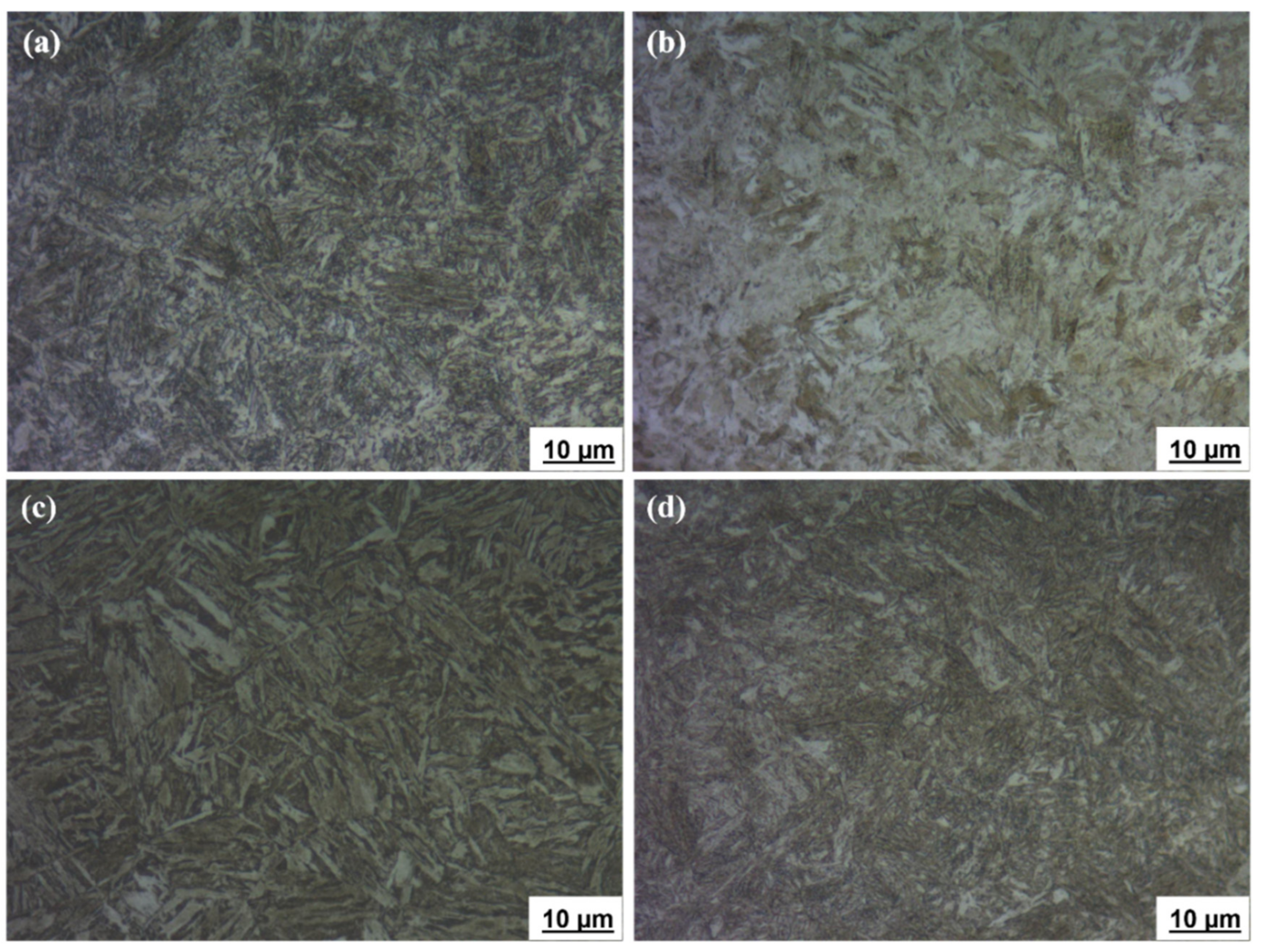
3.2.1. Optical Microscope

The microstructures of the ballistic steel samples were analyzed using an optical microscope at 1000× magnification, as shown in Figure 1. The microstructures were revealed to be tempered martensite, and precipitation of carbides was also noticed in all the samples. However, martensite was more homogenously distributed in the HT samples than in the other counterparts. This facilitates increased strength, hardness and toughness. In general, a lath martensite morphology can be observed in all the microstructures.

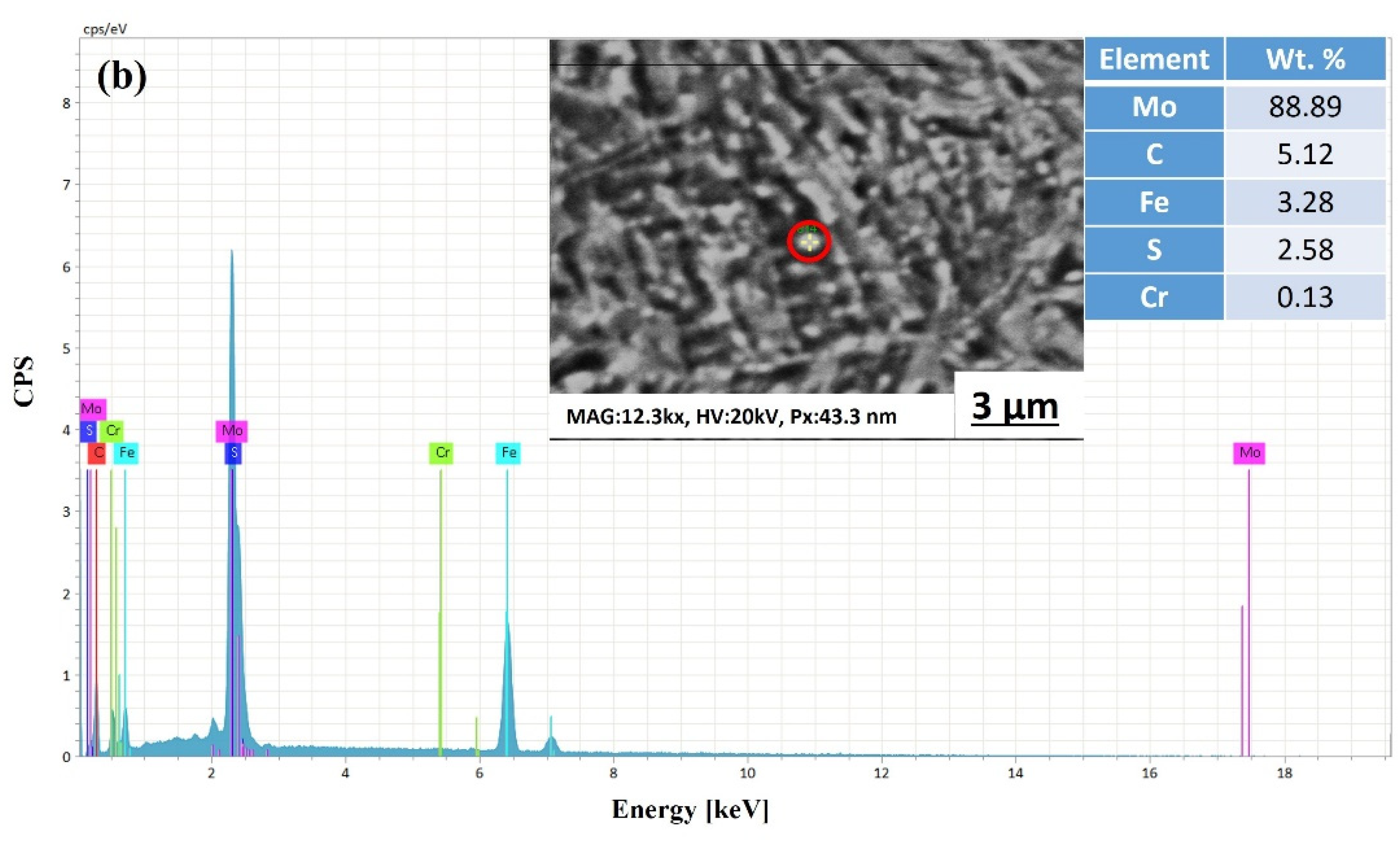
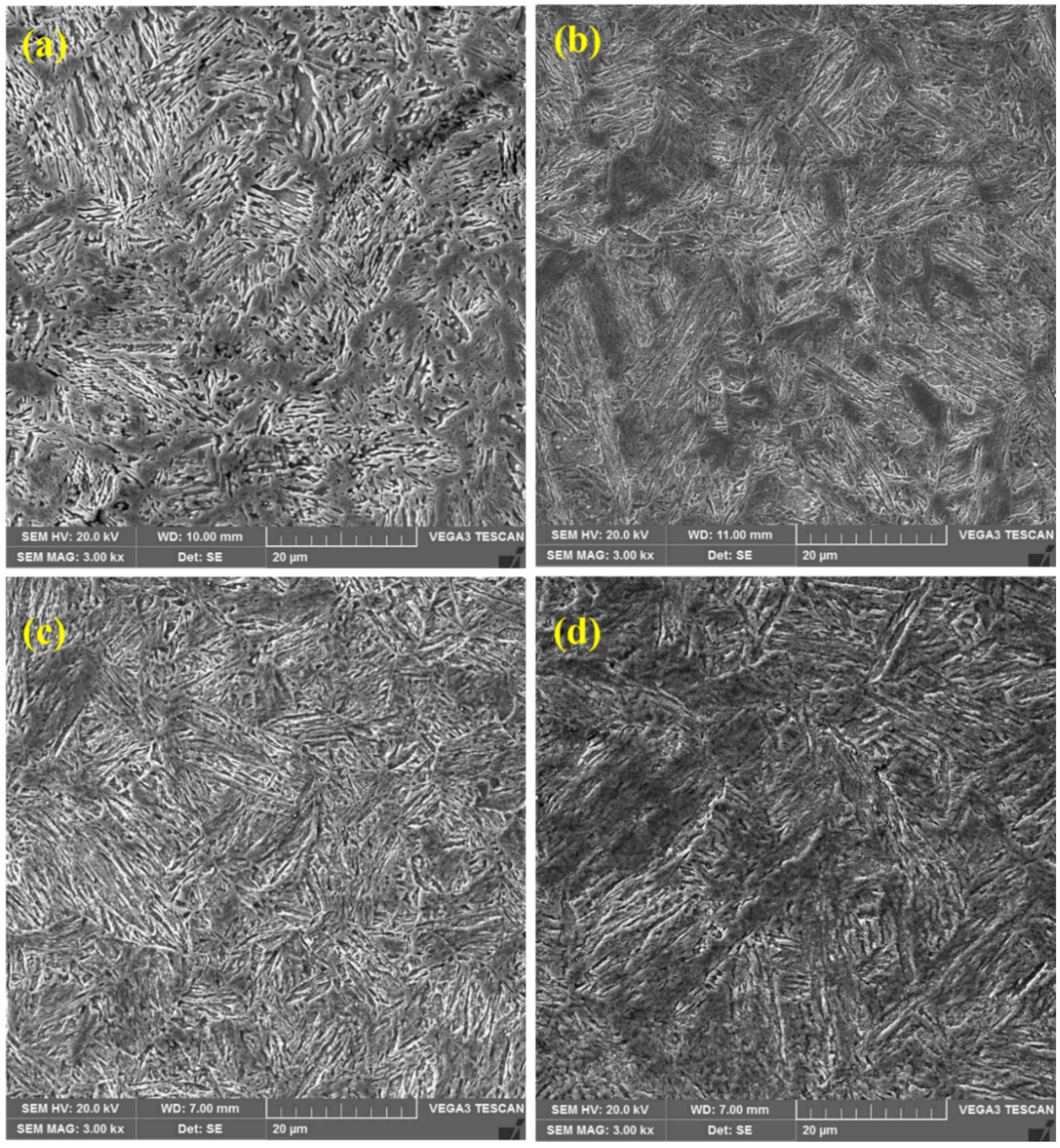
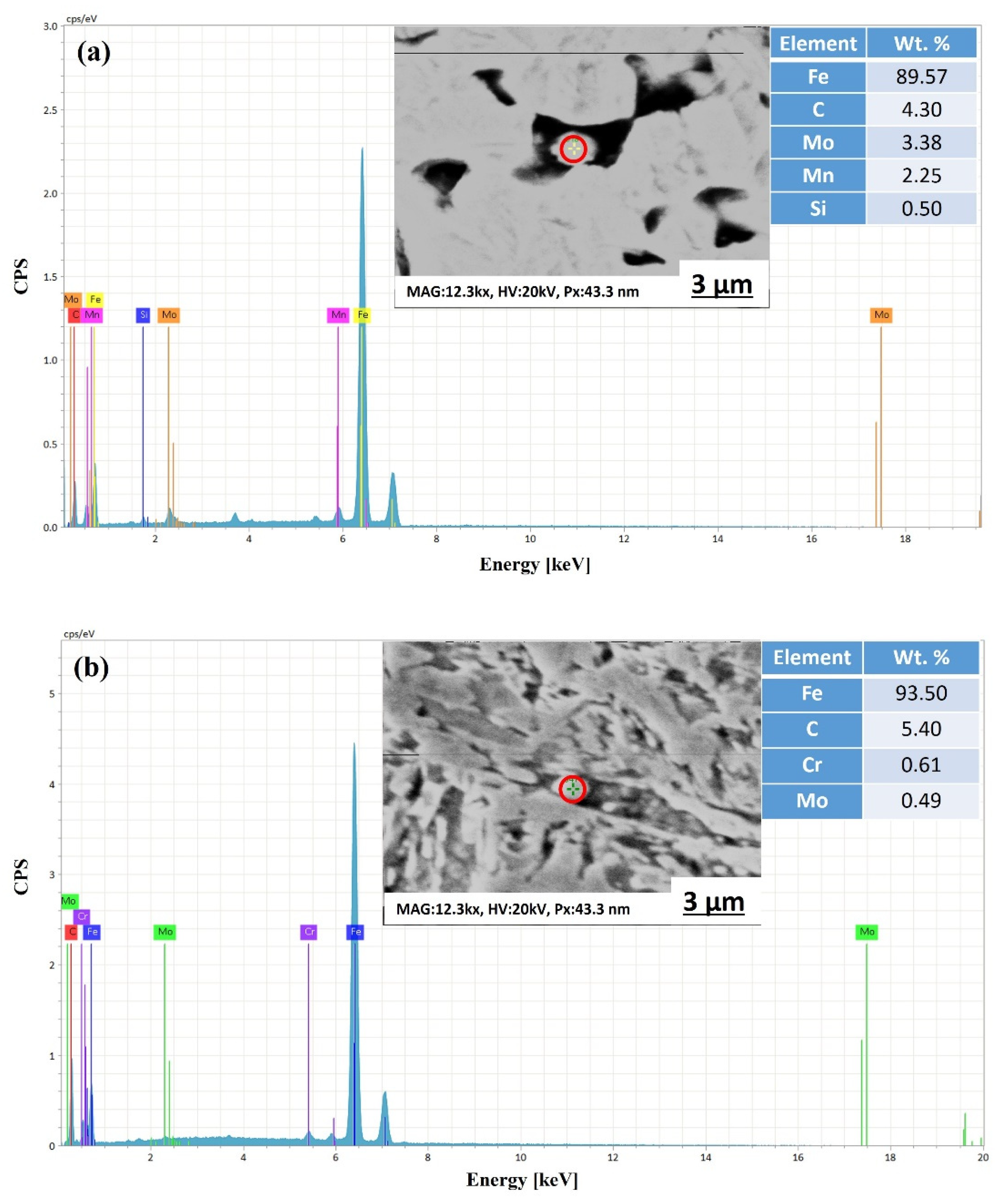
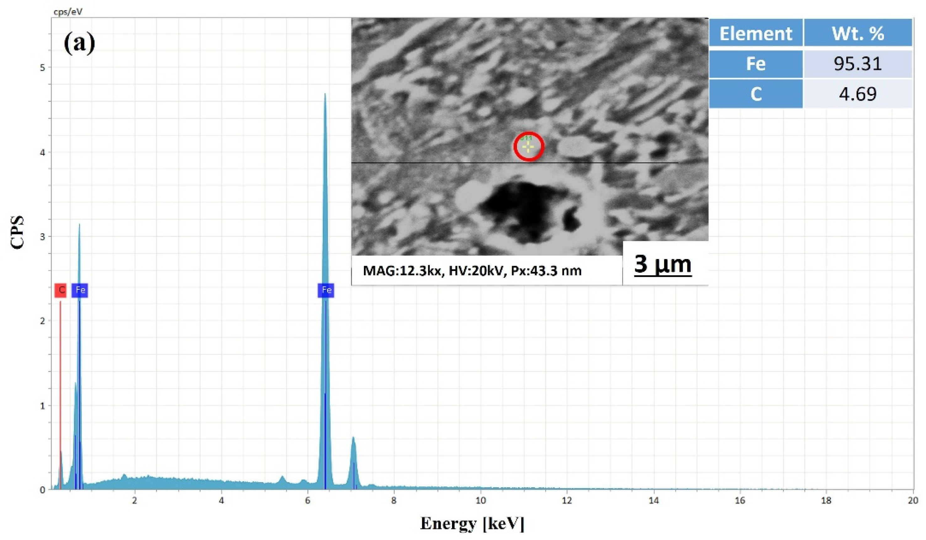
3.2.2. Scanning Electron Microscope

Scanning electron microscopy was used to analyze the microstructures of the ballistic steel samples at varying magnifications. The SEM micrographs are shown in Figure 2a–d. The presence of martensite laths with carbide precipitations was also observed, which is consistent with the optical images. In particular, the lath and grain sizes of martensite are nearly similar in all the samples. However, no retained austenite was observed in the samples, since it was transformed into ferrite and carbides. In the HT samples, epsilon (ε) carbides and molybdenum carbides were observed, while LT only exhibited ε-carbides.
Moreover, the EDS point analysis of the LT samples only indicated the precipitation of ε-carbides (see Figure 3), while the HT samples exhibited (see Figure 4) the precipitation of both ε-carbides and Mo2C (molybdenum carbides), which is consistent with previous studies [36,37].

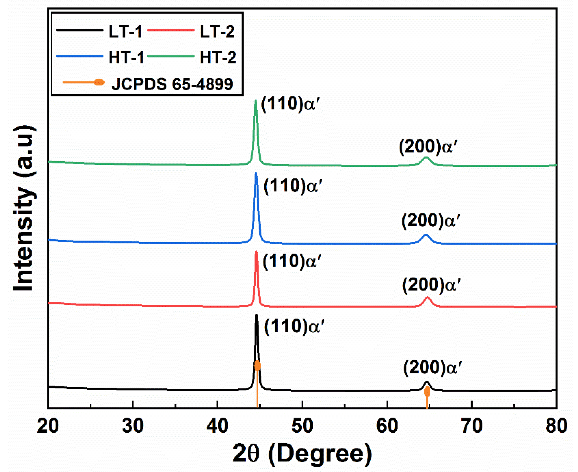
3.3. X-ray Diffraction Analysis

The X-ray diffraction patterns of the ballistic steel samples are shown in Figure 5. The X-ray diffraction patterns only show martensitic peaks, i.e., (110)α’ and (200)α’, in both the LT and HT samples, respectively. It should be noted that no retained austenite was observed in the XRD analysis, which further confirms the fully tempered martensite structure in all the samples.

3.4. Mechanical Properties

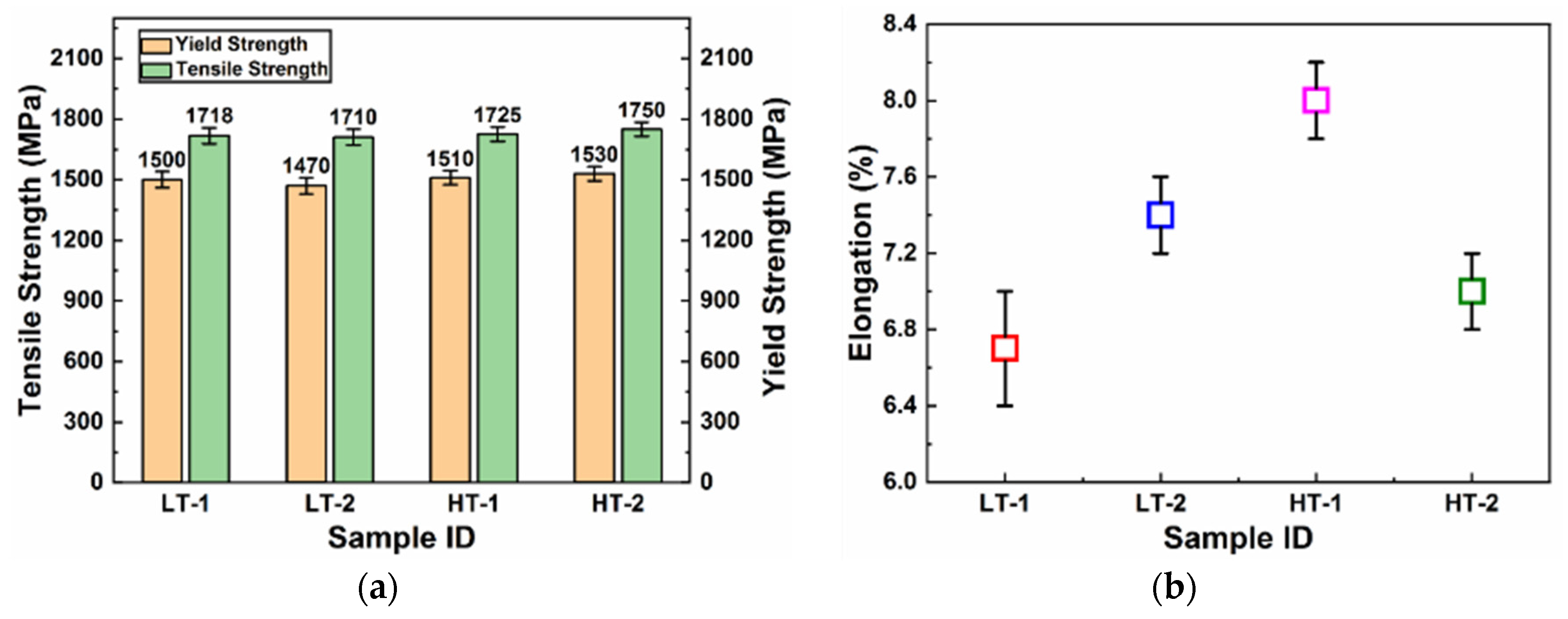
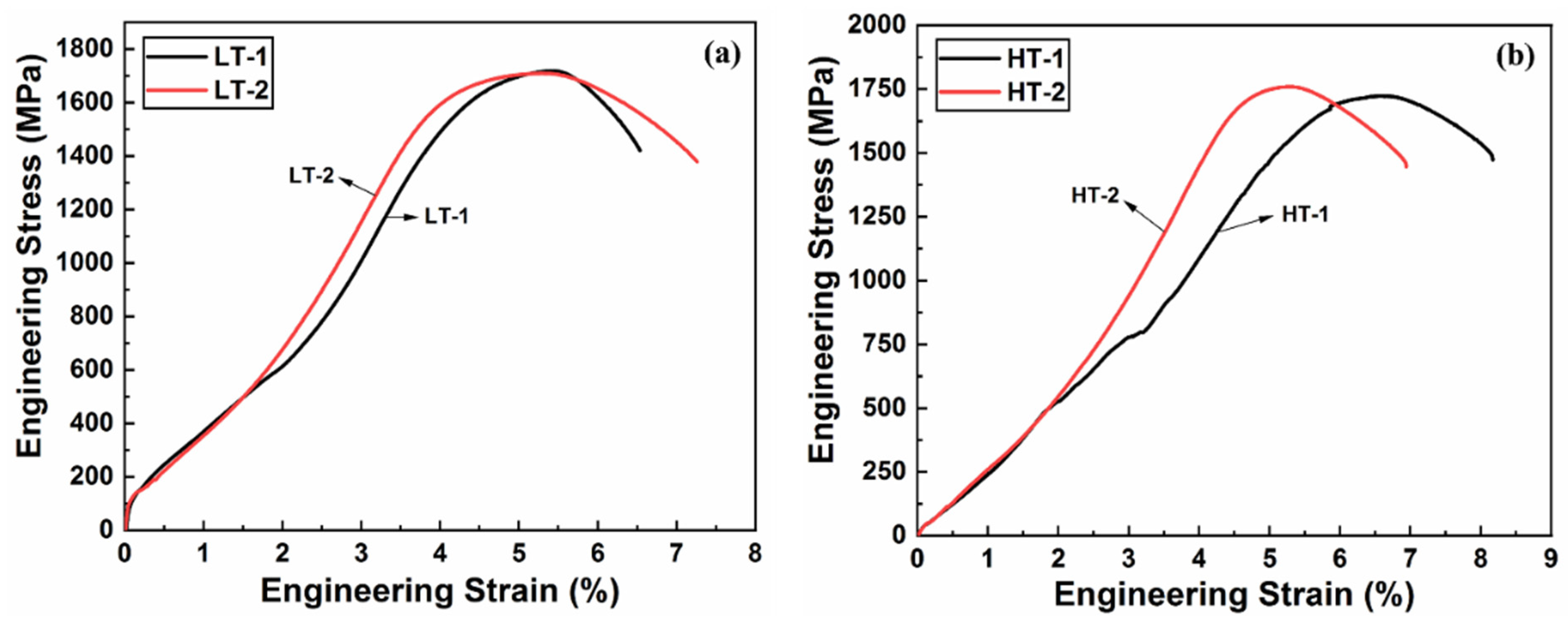
3.4.1. Tensile Properties

The tensile properties, and some other properties, such as toughness and hardness, were also measured for the ballistic steel samples, as shown in Table 5. Figure 6 shows engineering stress and strain curves of the ballistic steel samples, whose detailed extracted data are shown in Figure 7. It can be analyzed from the data that the yield, elongation and tensile strength values of the HT samples are higher than those of their LT counterparts, due to a scale effect. Percent elongation represents the ductility of the material, thereby suggesting that the HT samples are more ductile than their LT counterparts. This change in properties is attributed to the microstructure, i.e., precipitates and homogeneity. In addition, it is due to a slight variation in the chemical composition of both sets of samples, as shown in Table 4.

3.4.2. Impact Resistance

The impact properties of the ballistic steel samples were also measured using the Charpy test. Impact energy is an indication of the energy required for crack initiation and propagation. Thus, the toughness values for the LT samples were measured to be 38 and 44 joules for LT-1 and LT-2, respectively. On the contrary, 68 and 55 joules were obtained for HT-1 and HT-2, respectively, as represented in Table 5 and Figure 8. This suggests that the LT-2 sample is tougher than the LT-1 sample in the same category, while HT-1 appeared to be tougher than its HT-2 counterpart. However, in general, the HT samples were revealed to be tougher than their LT counterparts.

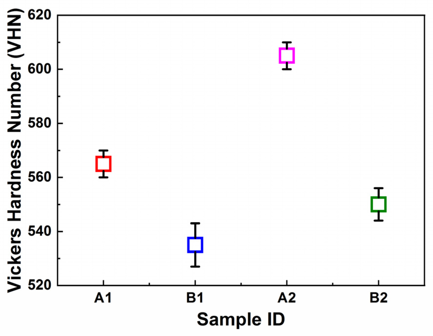
3.4.3. Vickers Microhardness

The hardness of the ballistic steel samples was measured using Vickers microhardness tester. The hardness values for the LT samples were measured to be 535 VHN (Vickers hardness number) and 560 VHN for LT-1 and LT-2, respectively. The HT samples were measured to be 590 VHN and 550 VHN for HT-1 and HT-2, respectively, as shown in Table 5 and Figure 9. The hardness values of the samples indicate that the LT-1 sample is harder than the LT-2 sample, whereas the HT-1 sample is harder than the HT-2 sample. However, in general, the results revealed that the HT samples are harder in comparison with the LT samples.

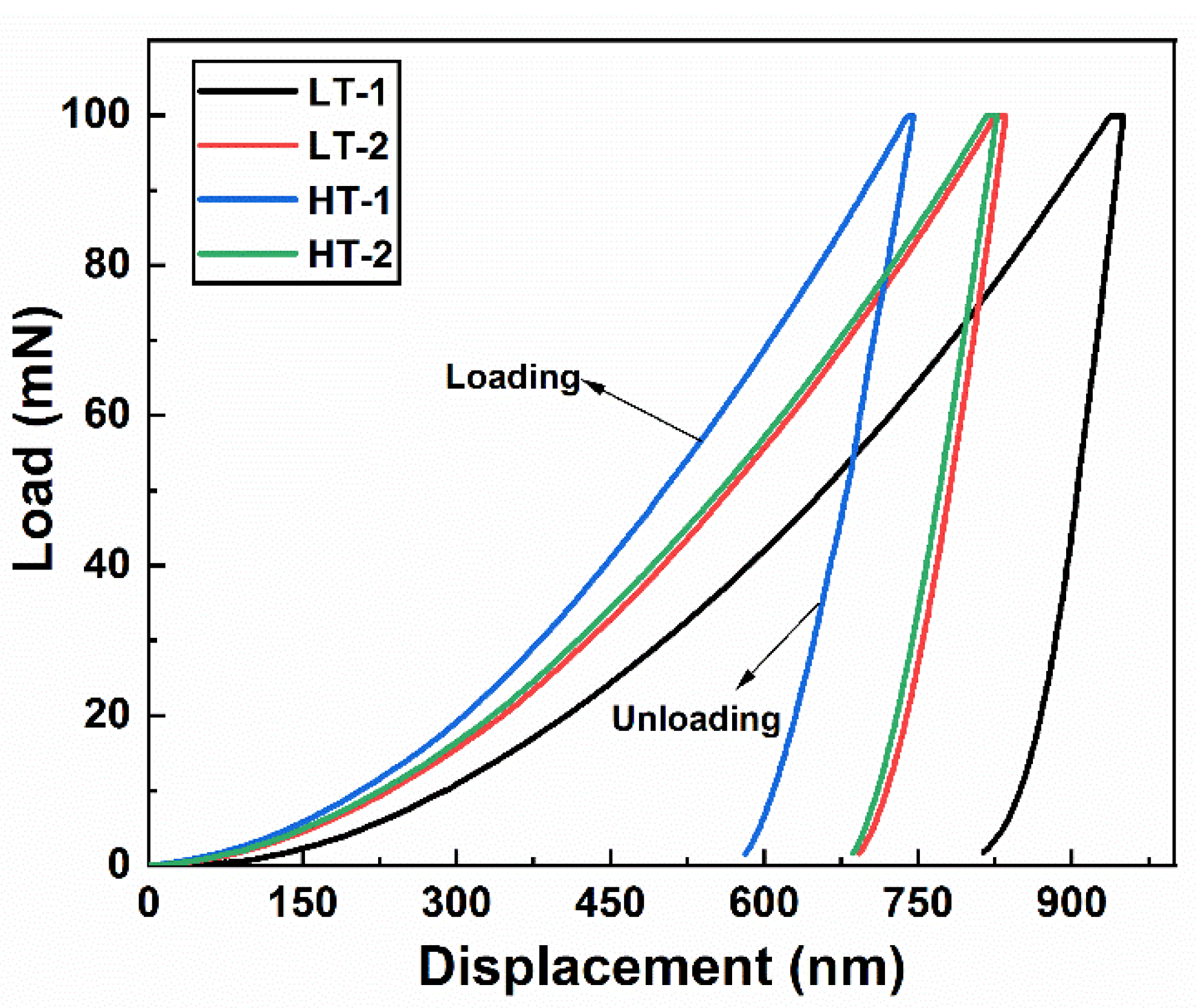
3.4.4. Nanoindentation Analysis
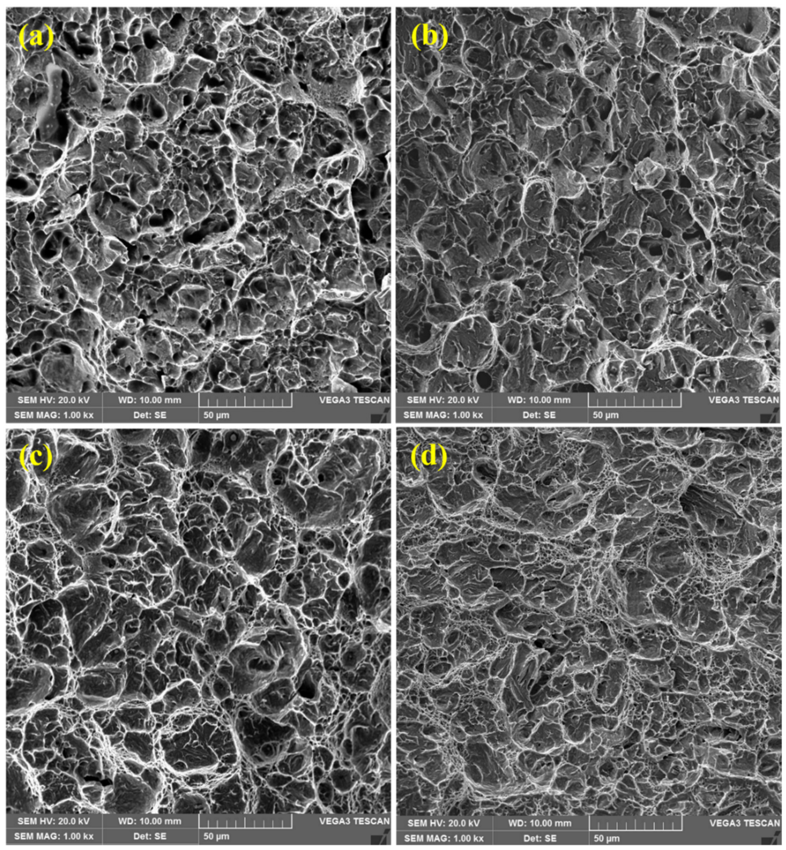
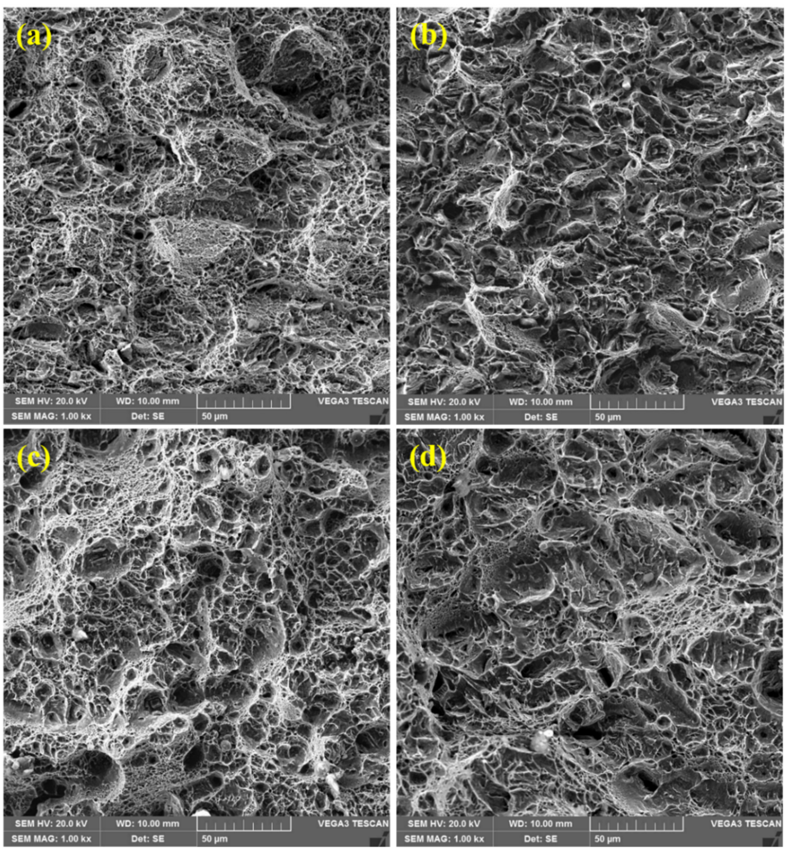
To better understand the mechanical properties of ballistic steel, such as the indentation hardness (H), elastic modulus (E), reduced elastic modulus (Er) and stiffness (S), nanoindentations were carried out. Thus, the indentation hardness (H) was calculated by using Equation (1) [34,38]:
H = F max A P
where Fmax = maximum load and Ap = indentation projected contact area.
Moreover, the reduced elastic modulus (Er) was calculated by using Equation (2) [34,38]:
E r = π · S 2 · β · A P h c
where S = stiffness, Ap = indentation projected contact area, hc = indentation contact depth and β = geometric constant with a unity value.
In addition, the plain strain elastic modulus (E*) was determined by using Equation (3):
E * = 1 1 E r 1 ν i 2 E i
where Ei = elastic modulus of the indenter and νi = Poisson’s ratio of the indenter.
The elastic modulus (E) was calculated by using Equation (4) [34,38]:
E =   E * ·   1 ν s 2
where E = elastic modulus of the sample and νs = Poisson’s ratio of the sample.
The load–displacement curves of the ballistic steel samples obtained using the nanoindentation tester are shown in Figure 10. In addition, the micromechanical properties, such as the indentation hardness, elastic modulus and stiffness, are shown in Table 6. The HT samples (in particular, the 15 mm sample) exhibited higher indentation hardness, and lower elastic modulus and stiffness than the other counterparts. This is due to the homogeneous distribution of lath martensite and carbide precipitation. This further suggests that for ballistic protection applications, the martensitic phase is the most desirable structure of steels. This is because it provides optimum mechanical and ballistic performance [23].

3.5. Fractography

3.5.1. Tensile Samples

A scanning electron microscope was used to examine the fractured surfaces of the samples, so as to understand the mode of failure. Figure 11 illustrates fractured surfaces of tensile samples, whereby necking regions could be observed in the samples. Fibrous and shiny surface features, along with significant amounts of deformation, thereby forming shearing lips at the corners of the samples, could be observed. Therefore, failure occurs after necking in tensile samples by localized shear plastic. It should be noted that the dimple is a distinguished feature of a ductile fracture, as observed in the present case.
Moreover, micro-voids and smooth facets can be observed in all the tensile samples, since fracturing takes place in alloys by micro-void nucleation and coalescence. This is due to a pile-up of dislocations, grain boundaries, inclusions and carbide particles [39]. Figure 11 represents large amounts of variation in dimple size and shape on the fracture surfaces. Thus, all the samples exhibited ductile failures.

3.5.2. Impact Samples

Figure 12 shows fractured surfaces of the samples after impact testing. All the fractured surfaces exhibit equiaxed dimples, along with micro-voids, similarly, presumably, to the crack initiated and propagated from the region of micro-voids [39]. The similar morphology of the dimples in all the samples suggests that this is a ductile failure. This is consistent with the observations of tensile fractures discussed earlier.
Moreover, it should be noted that hardness, strength, and toughness are properties of prime importance for ballistic steels, which were found to be better for the HT samples than for all the other samples presently studied.

3.5.3. Microstructure and Mechanical Behavior Co-Relationships

The morphology of the fracture surfaces of the samples after both the tensile and impact tests shows a relation between the mechanical behavior of the samples and the microstructure of the corresponding materials. As mentioned above, all the microstructures were characterized by a lath martensite morphology. However, a great degree of homogeneity of tempered martensite was observed in the HT samples compared to that of their LT counterparts. In the LT samples (Figure 1a,b and Figure 2a,b), quite distinct packets of martensite laths can be observed. The average size of the packets is about 7–10 μm. For the HT-2 sample, the packets of martensite laths are about the same size, but their contours are blurred (Figure 1d). In contrast to this, a homogeneous lath martensite microstructure is observed for the HT-1 sample (Figure 1c and Figure 2c). As can be observed in Figure 11c and especially, in Figure 12c, the fracture surface of the HT-1 sample contains plastic elongation crests surrounding a set of dimples. Such crests are of a greater size (about 50–100 μm, see Figure 12c), and are more distinct than those of other variants. That is why, at similar levels of tensile strength, greater elongation is achieved for the HT-1 sample (see Table 5). Such a ductile fracture micromechanism also explains the increased toughness (impact resistance), due to enhanced ductility of the material (see Table 5).

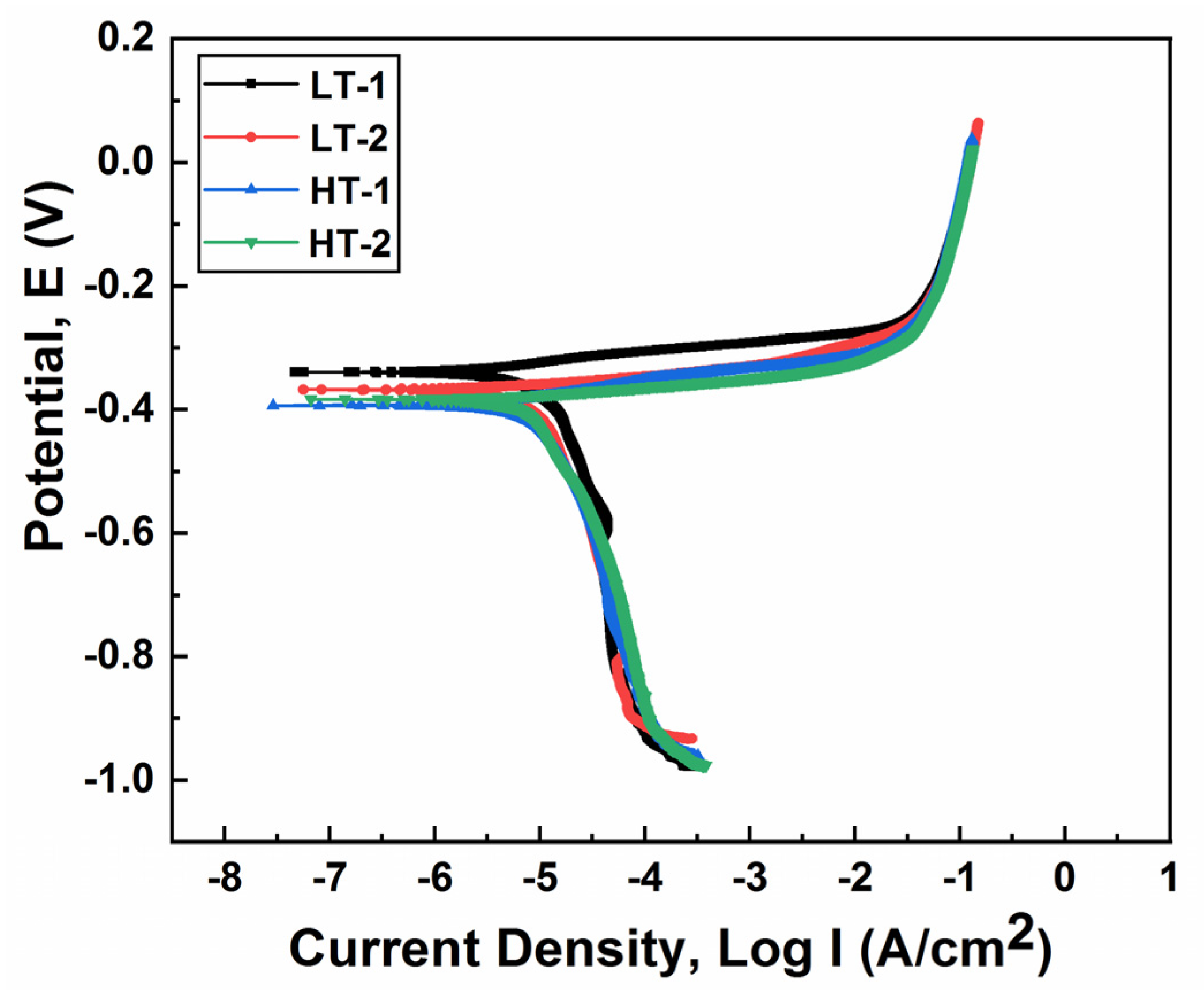
3.6. Corrosion Analysis

Potentiodynamic polarization curves were obtained in 3.5 wt.% NaCl solution, as shown in Figure 13. The corrosion current density (Icorr) and corrosion potential (Ecorr) were determined by Tafel extrapolation techniques, whereas the corrosion rate was calculated using Equation (4) [40].
Corrosion   rate   mm year = I corr   × 0.00327 ×   EW ρ
where I corr = corrosion current density (µA/cm2), EW = equivalent weight of iron (27.92) and ρ = density of ballistic steel (7.850 g/cm3).
The corrosion parameters were obtained from Tafel curves using the extrapolation technique, as shown in Table 7. In general, the results revealed that the LT samples exhibited a lower corrosion current density (Icorr), corrosion potential (Ecorr) and, hence, corrosion rate. On the other hand, the HT samples exhibited a higher corrosion current density (Icorr), corrosion potential (Ecorr) and, thus, corrosion rate. The reduction in the corrosion rate of the LT samples is due to the presence of ε-carbides and more chromium, and the less homogeneous distribution of the martensite phase. It should be noted that the tempered martensite structure always exhibits a larger corrosion rate when compared to other steels. Nevertheless, the increase in the corrosion rate of the HT samples is attributed to the more homogeneous distribution of the martensite phase [40], ε-carbides [41] and Mo2C-carbides [42]. Presumably, this provides more nucleation sites for corrosion cells to develop. Thus, the LT samples are more corrosion resistant when compared to their HT counterparts.

4. Conclusions

Based on the present set of experimental conditions adopted for low-thickness and high-thickness ballistic steel samples, the following are the concluding remarks. The aim of this study was to better understand the existing materials used for armoring applications, in particular, for civil and military vehicles, in addition to their corrosion behaviors.
The microstructures of all the samples were analyzed, wherein the LT samples only exhibited ε-carbide precipitates, whereas the HT samples contained both ε-carbides and Mo2C-carbides. In addition, a greater degree of homogeneity of tempered martensite was observed in the HT samples than in their LT counterparts. Hence, improved mechanical properties (i.e., tensile properties, toughness and hardness) of the same were observed. In addition, the fracture modes were ductile in nature, which implies ease of application of such materials. Moreover, the corrosion resistance of the HT samples was found to be poor in comparison to their LT counterparts. This was attributed to the microstructure, i.e., homogeneity and precipitates. Thus, these findings will facilitate the development of conventional steels for potential armoring applications. Therefore, the HT samples are a better choice for armoring applications at an advanced level of protection.

Author Contributions

In this article W.K. has performed all experimental work; M.T. (the co-supervisor of his Ph.D. project and he helped him in terms of providing up to date guidance and academic writing); A.D.C. (main supervisor of this project. Thus, he provided guidance in experimentation, writeup of manuscript, English proofreading etc.). All authors have read and agreed to the published version of the manuscript.

Funding

NED University of Engineering and Technology, Karachi Pakistan provided the funding for this research. The grant number for funding is Acad/50/(48)/2164.

Institutional Review Board Statement

Not Applicable.

Informed Consent Statement

Not Applicable.

Data Availability Statement

Not Applicable.

Acknowledgments

The authors are grateful for local organizations, such as Pak Armoring and Streit Pakistan, for supplying ballistic steel plates. The authors would also like to thank the lab staff of Peoples Steel Mills Limited and Metallurgical Engineering Department, NED University of Engineering and Technology for their support during experimentation.

Conflicts of Interest

The authors have no conflict of interest to declare.

References

  1. Edwards, M.; Mathewson, A. The ballistic properties of tool steel as a potential improvised armour plate. Int. J. Impact Eng. 1997, 19, 297–309. [Google Scholar] [CrossRef]
  2. Shokrieh, M.; Javadpour, G. Penetration analysis of a projectile in ceramic composite armor. Compos. Struct. 2008, 82, 269–276. [Google Scholar] [CrossRef]
  3. Madhu, V.; Bhat, T.B. Armour Protection and Affordable Protection for Futuristic Combat Vehicles. Def. Sci. J. 2011, 61, 394–402. [Google Scholar] [CrossRef] [Green Version]
  4. Jena, K.; Manickam, M.A.M.; Venketachari, S.; Srivastava, S.C.; Srivastava, A.; Chakrabarty, S.; Kumar, K.S. Microstructure, mechanical, ballistic property evaluation of RHA steel produced by continuous-casting route. J. Appl. Res. Technol. 2020, 18, 1–13. [Google Scholar] [CrossRef]
  5. Manganello, S.; Wilson, A. Direct Quenching and its Effects on High-Strength Armor Plate. In Proceedings of the International Symposium on Low-Carbon Steels for the 90’s, Pittsburgh, PA, USA, 18–21 October 1993; The Minerals, Metals & Materials Society: Pittsburgh, PA, USA, 1993; pp. 235–241. [Google Scholar]
  6. Atapek, S.H.; Karagoz, S. Ballistic impact behaviour of a tempered bainitic steel against 7.62 mm armour piercing projectile. Def. Sci. J. 2011, 61, 81. [Google Scholar] [CrossRef] [Green Version]
  7. Dikshit, S.; Kutumbarao, V.; Sundararajan, G. The influence of plate hardness on the ballistic penetration of thick steel plates. Int. J. Impact Eng. 1995, 16, 293–320. [Google Scholar] [CrossRef]
  8. Demir, T.; Übeyli, M.; Yıldırım, R.O. Investigation on the ballistic impact behavior of various alloys against 7.62 mm armor piercing projectile. Mater. Des. 2008, 29, 2009–2016. [Google Scholar] [CrossRef]
  9. Jena, P.K.; Kumar, K.S.; Bhat, T.B. Effect of heat treatment on mechanical and ballistic properties of ultrahigh strength DMR-1700 steel. Met. Mater. Processes 2007, 19, 339. [Google Scholar]
  10. Bekci, M.L.; Canpolat, C.H.; Usta, E.; Güler, M.S.; Cora, Ö.N. Ballistic performances of Ramor 500 and Ramor 550 armor steels at mono and bilayered plate configurations. Eng. Sci. Technol. Int. J. 2021, 24, 990–995. [Google Scholar] [CrossRef]
  11. Übeyli, M.; Yıldırım, R.O.; Ögel, B. On the comparison of the ballistic performance of steel and laminated composite armors. Mater. Des. 2007, 28, 1257–1262. [Google Scholar] [CrossRef]
  12. Jena, P.K.; Senthil, P. Effect of tempering time on the ballistic performance of a high strength armour steel. J. Appl. Res. Technol. 2016, 14, 47–53. [Google Scholar] [CrossRef]
  13. Jena, P.K.; Mishra, B.; Kumar, K.S.; Bhat, B.T. An experimental study on the ballistic impact behavior of some metallic armour materials against 7.62 mm deformable projectile. Mater. Des. 2010, 31, 3308–3316. [Google Scholar] [CrossRef]
  14. Mishra, B.; Jena, P.K.; Ramakrishna, B.; Madhu, V.; Bhat, T.B.; Gupta, N.K. Effect of tempering temperature, plate thickness and presence of holes on ballistic impact behavior and ASB formation of a high strength steel. Int. J. Impact Eng. 2012, 44, 17–28. [Google Scholar] [CrossRef]
  15. Maweja, K.; Stumpf, W.; van der Berg, N. Characteristics of martensite as a function of the Ms temperature in low-carbon armour steel plates. Mater. Sci. Eng. A 2009, 519, 121–127. [Google Scholar] [CrossRef] [Green Version]
  16. Lee, W.-S.; Su, T.-T. Mechanical properties and microstructural features of AISI 4340 high-strength alloy steel under quenched and tempered conditions. J. Mater. Processing Technol. 1999, 87, 198–206. [Google Scholar] [CrossRef]
  17. Malakondaiah, G.; Srinivas, M.; Rao, R. Ultrahigh-strength low-alloy steels with enhanced fracture toughness. Prog. Mater. Sci. 1997, 42, 209–242. [Google Scholar] [CrossRef]
  18. Channa, I.A.; Shah, A.A.; Abro, S.H.; Siddiqui, M.A.; Mujahid, M.; Chandio, A.D. Effect of Tempering Temperature on the Properties of Martensitic Stainless Steel AISI-420. J. Emerg. Technol. 2019, 2, 51–56. [Google Scholar]
  19. Wolsky, S.; Czanderna, A. Methods and Phenomena 5, Ballistic Materials and Penetration Mechanics; Elsevier Scientific Publishing Company: Berlin/Heidelberg, Germany, 1982. [Google Scholar]
  20. Srivathsa, B.; Ramakrishnan, N. Ballistic performance maps for thick metallic armour. J. Mater. Processing Technol. 1999, 96, 81–91. [Google Scholar] [CrossRef]
  21. Maweja, K.; Stumpf, W. The design of advanced performance high strength low-carbon martensitic armour steels: Part 1. Mechanical property considerations. Mater. Sci. Eng. A 2008, 485, 140–153. [Google Scholar] [CrossRef]
  22. Ahmad, S.; Channa, I.A. Mathematical relationship between ferritic, pearlitic and average grain size of steel. J. Mod. Sci. Technol. 2013, 1, 1–18. [Google Scholar]
  23. Jena, P.K.; Mishra, B.; RameshBabu, M.; Babu, A.; Singh, A.K.; SivaKumar, K.; Balakrishna Bhat, T. Effect of heat treatment on mechanical and ballistic properties of a high strength armour steel. Int. J. Impact Eng. 2010, 37, 242–249. [Google Scholar] [CrossRef]
  24. Konca, E. A Comparison of the Ballistic Performances of Various Microstructures in MIL-A-12560 Armor Steel. Metals 2020, 10, 446. [Google Scholar] [CrossRef] [Green Version]
  25. Zhang, P.; Chen, Y.; Xiao, W.; Ping, D.; Zhao, X. Twin structure of the lath martensite in low carbon steel. Prog. Nat. Sci. Mater. Int. 2016, 26, 169–172. [Google Scholar] [CrossRef] [Green Version]
  26. Bhat, T.B. Principles of armor design. Trans. Indian Inst. Met. 1984, 37, 313–335. [Google Scholar]
  27. Atapek, S.H. Development of a new armor steel and its ballistic performance. Def. Sci. J. 2013, 63, 271–277. [Google Scholar] [CrossRef] [Green Version]
  28. Whittington, W.R.; Oppedal, A.L.; Turnage, S.; Hammi, Y.; Rhee, H.; Allison, P.G.; Crane, C.K.; Horstemeyer, M.F. Capturing the effect of temperature, strain rate, and stress state on the plasticity and fracture of rolled homogeneous armor (RHA) steel. Mater. Sci. Eng. A 2014, 594, 82–88. [Google Scholar] [CrossRef]
  29. Katiyar, P.K.; Behera, P.K.; Misra, S.; Mondal, K. Comparative corrosion behavior of five different microstructures of rebar steels in simulated concrete pore solution with and without chloride addition. J. Mater. Eng. Perform. 2019, 28, 6275–6286. [Google Scholar] [CrossRef]
  30. Handoko, W.; Pahlevani, F.; Sahajwalla, V.J.M. Enhancing corrosion resistance and hardness properties of carbon steel through modification of microstructure. Materials 2018, 11, 2404. [Google Scholar] [CrossRef] [Green Version]
  31. Showalter, D.D.; Gooch, W.A.; Burkins, M.S.; Koch, R.S. Ballistic Testing of SSAB Ultra-High-Hardness Steel for Armor Applications; Weapons and Materials Research; Army Research Lab: Aberdeen Proving Ground, MD, USA, 2008. [Google Scholar]
  32. Gooch, W.; Burkins, M.S.; Squillacioti, R.; Stockman Koch, R.-M.; Oscarsson, H.; Nash, C. Ballistic testing of Swedish steel armox plate for US armor applications. In Proceedings of the 21st International Ballistic Symposium, Adelaide, Australia, 19–23 April 2004. [Google Scholar]
  33. Weissmann, S. Search Manual for Selected Powder Diffraction Data for Metals and Alloys; JCPDS International Center for Diffraction Data: Swarthmore, PA, USA, 1978. [Google Scholar]
  34. Oliver, W.C.; Pharr, G.M. An improved technique for determining hardness and elastic modulus using load and displacement sensing indentation experiments. J. Mater. Res. 1992, 7, 1564–1583. [Google Scholar] [CrossRef]
  35. Fischer-Cripps, A.C. Introduction to Contact Mechanics; Springer: Berlin/Heidelberg, Germany, 2007; Volume 101. [Google Scholar]
  36. Deng, X.; Fu, T.L.; Wang, Z.D.; Misra, R.D.K.; Wang, G.D. Epsilon carbide precipitation and wear behaviour of low alloy wear resistant steels. Mater. Sci. Technol. 2016, 32, 320–327. [Google Scholar] [CrossRef]
  37. Thomson, R.; Miller, M. Carbide precipitation in martensite during the early stages of tempering Cr-andMo-containing low alloy steels. Acta Mater. 1998, 46, 2203–2213. [Google Scholar] [CrossRef]
  38. Doerner, M.F.; Nix, W.D. A method for interpreting the data from depth-sensing indentation instruments. J. Mater. Res. 1986, 1, 601–609. [Google Scholar] [CrossRef]
  39. Karagöz, Ş.; Atapek, Ş.H.; Yilmaz, A. Microstructural and fractographical studies on quenched and tempered armor steels. Mater. Test. 2010, 52, 316–322. [Google Scholar] [CrossRef] [Green Version]
  40. Katiyar, P.K.; Misra, S.; Mondal, K. Comparative corrosion behavior of five microstructures (pearlite, bainite, spheroidized, martensite, and tempered martensite) made from a high carbon steel. Metall. Mater. Trans. A 2019, 50, 1489–1501. [Google Scholar] [CrossRef]
  41. Inam, A.; Hafeez, M.A.; Atif, M.; Ishtiaq, M.; Hassan, M.H.; Hussain, T.; Mughal, M.S.; Raza, M.A.; Abbas, M.A.Q.; Ullah, I. Microstructural, Mechanical, and Electrochemical Properties of Quenched and Partitioned 3 wt% Mn Steel. Arab. J. Sci. Eng. 2021, 46, 417–423. [Google Scholar] [CrossRef]
  42. Wan, H.; Cai, Y.; Song, D.; Chen, S. Effect of Cr/Mo carbides on corrosion behaviour of Fe_Mn_C twinning induced plasticity steel. Corros. Sci. 2020, 167, 108518. [Google Scholar] [CrossRef]
Figure 1. Optical microstructures of ballistic steel samples: (a) LT-1; (b) LT-2; (c) HT-1; (d) HT-2.
Materials 15 02204 g001
Figure 2. SEM micrographs of ballistic steel samples: (a) LT-1; (b) LT-2; (c) HT-1; (d) HT-2.
Materials 15 02204 g002
Figure 3. EDS spectra of LT samples at different locations, i.e., (a,b). Precipitates were measured using point scanning.
Materials 15 02204 g003
Figure 4. EDS spectra of HT samples at different locations, i.e., (a,b). Precipitates were measured using point scanning.
Materials 15 02204 g004aMaterials 15 02204 g004b
Figure 5. X-ray diffraction pattern of ballistic steel samples.
Materials 15 02204 g005
Figure 6. Engineering stress and strain plots of ballistic steel samples: (a) LT-1/LT-2 and (b) HT-1/HT-2.
Materials 15 02204 g006
Figure 7. Tensile properties of ballistic steel samples: (a) yield and tensile strength; (b) percent elongation.
Materials 15 02204 g007
Figure 8. Charpy impact properties of ballistic steel samples.
Materials 15 02204 g008
Figure 9. Vickers microhardness of ballistic steel samples.
Materials 15 02204 g009
Figure 10. Load–displacement curves of ballistic steel samples.
Materials 15 02204 g010
Figure 11. SEM fractographs of tensile samples: (a) LT-1; (b) LT-2; (c) HT-1; (d) HT-2. All of these samples exhibit ductile fractures.
Materials 15 02204 g011
Figure 12. SEM fractographs of impact tested samples: (a) LT-1; (b) LT-2; (c) HT-1; (d) HT-2. Similarly to tensile counterparts, all samples exhibited ductile fractures.
Materials 15 02204 g012
Figure 13. Potentiodynamic polarization curves of ballistic steel samples in 3.5 wt.% NaCl solution.
Materials 15 02204 g013
Table 1. The materials utilized in the present study.
S.No.Sample IDMaterial DetailsThicknessThreat LevelSupplier
1*LT-1Ballistic Steel7.0 mmFB6Pak Armoring
2*LT-2Ballistic Steel6.7 mmFB6Streit Pakistan
3**HT-1Ballistic Steel15.0 mmFB7Pak Armoring
4**HT-2Ballistic Steel13.0 mmFB7Streit Pakistan
*LT = low-thickness plate, **HT = high-thickness plate.
Table 2. The chemical composition of standard material (Armox 500T) (SSAB, Stockholm, Sweden) used for potential armoring applications.
Chemical Composition (wt. %)
ElementsCSiMnPSCrMoNiBFe
Standard Limit0.32 max0.50 max1.30 max0.010 max0.005 max1.00 max0.70 max1.80 max0.005 maxBalance
Table 3. The mechanical properties of standard material (Armox 500T) used for potential armoring applications.
MaterialMechanical Properties
Armox 500TYield Strength (MPa)Tensile Strength (MPa)Elongation (%)Vickers Hardness Number (VHN)Impact Toughness (J)
1250–14501450–17507–10530–620Min 25
Table 4. Chemical composition of ballistic steel samples.
Sample IDChemical Composition (wt. %)
CMnSiPSCrNiMoBFe
LT-10.260.900.300.0060.0010.900.960.260.003Balance
LT-20.291.350.550.0090.0030.700.440.270.002Balance
HT-10.301.000.380.0050.0040.600.380.420.004Balance
HT-20.301.300.520.0070.0020.600.400.340.003Balance
Table 5. Mechanical properties of ballistic steel samples.
Sample IDYield Strength (MPa)Tensile Strength (MPa)Elongation (%)Charpy Impact Energy (J)Vickers Hardness Number (VHN)
LT-1150017186.738535
LT-2147017107.444560
HT-1151017258.068590
HT-2153017507.055540
Table 6. Micro-mechanical properties of ballistic steel samples.
Sample IDHardness (H) (GPa)Elastic Modulus (E) (GPa)Stiffness (S) (mN/nm)
LT-16.80265.870.9880
LT-27.95244.260.8199
HT-18.20240.940.7908
HT-27.42252.750.9572
Table 7. Corrosion parameters of ballistic steel samples obtained from Tafel curves.
Sample IDIcorr (A/cm2)Ecorr (V)Corrosion Rate (mm/Year)
LT-13.60 × 10⁻⁶−0.3400.0418
LT-24.10 × 10⁻⁶−0.3680.0476
HT-15.30 ×10⁻⁶−0.3940.0615
HT-25.10 × 10⁻⁶−0.3840.0592
Publisher’s Note: MDPI stays neutral with regard to jurisdictional claims in published maps and institutional affiliations.

