
Development and Verification Experiment of In-Situ Friction Experiment Device for Simulating UV Irradiation in Space


Abstract
:1. Introduction
2. Materials and Methods
2.1. Development of a Space Ultraviolet Radiation Simulator
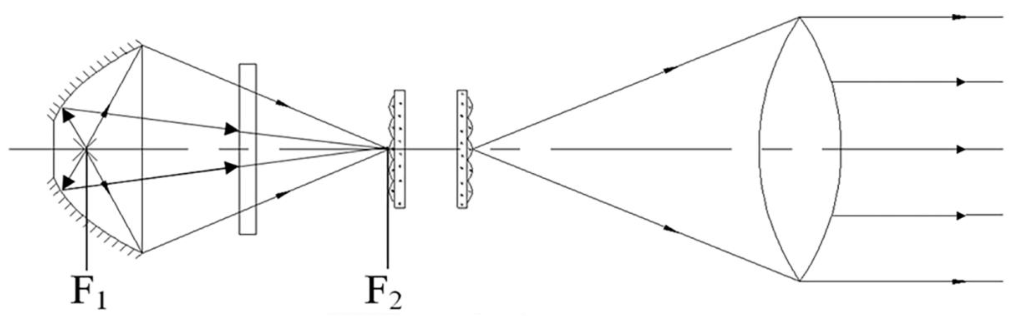
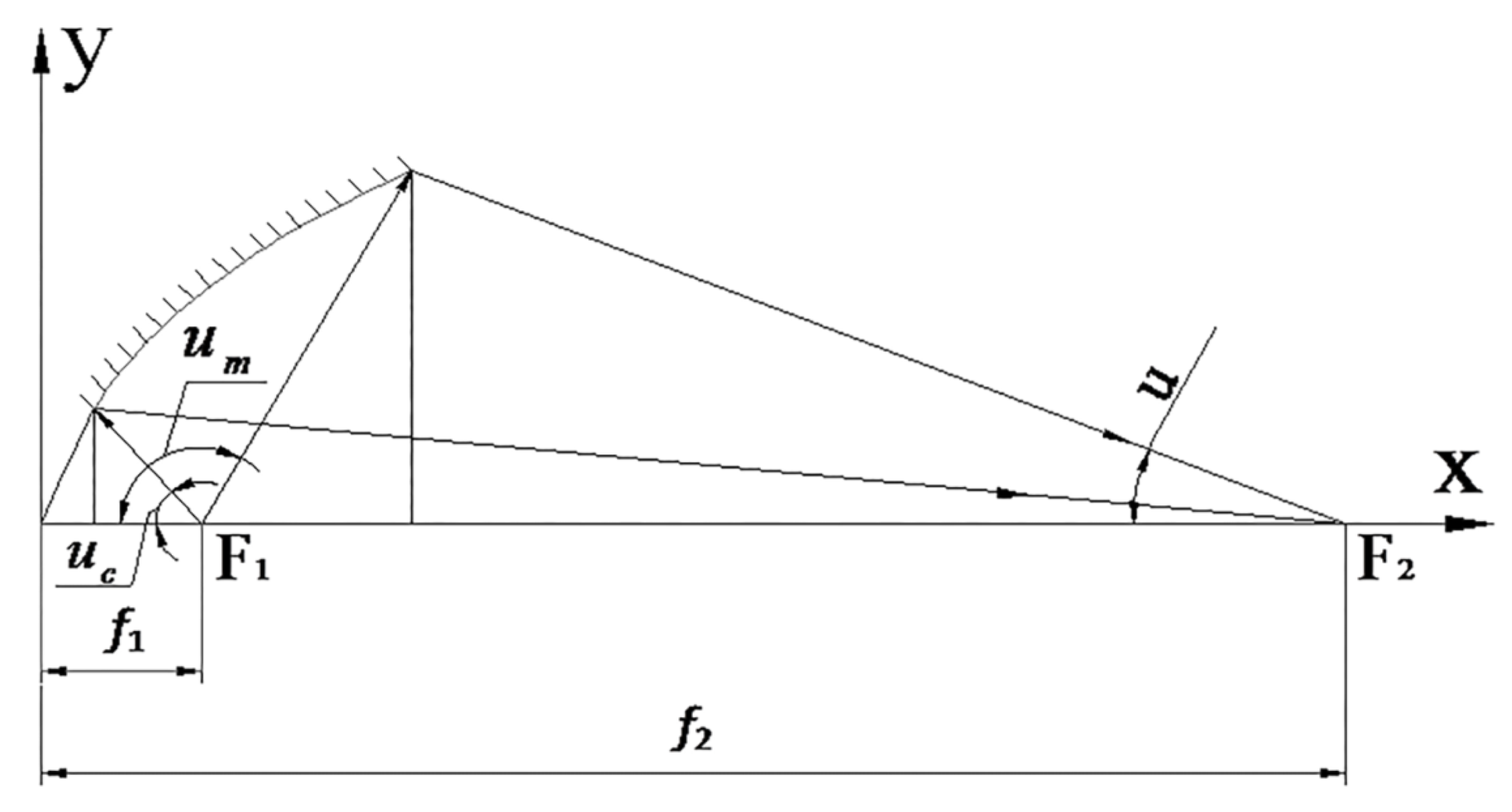
2.1.1. Integral Structure of Space Ultraviolet Radiation Simulator
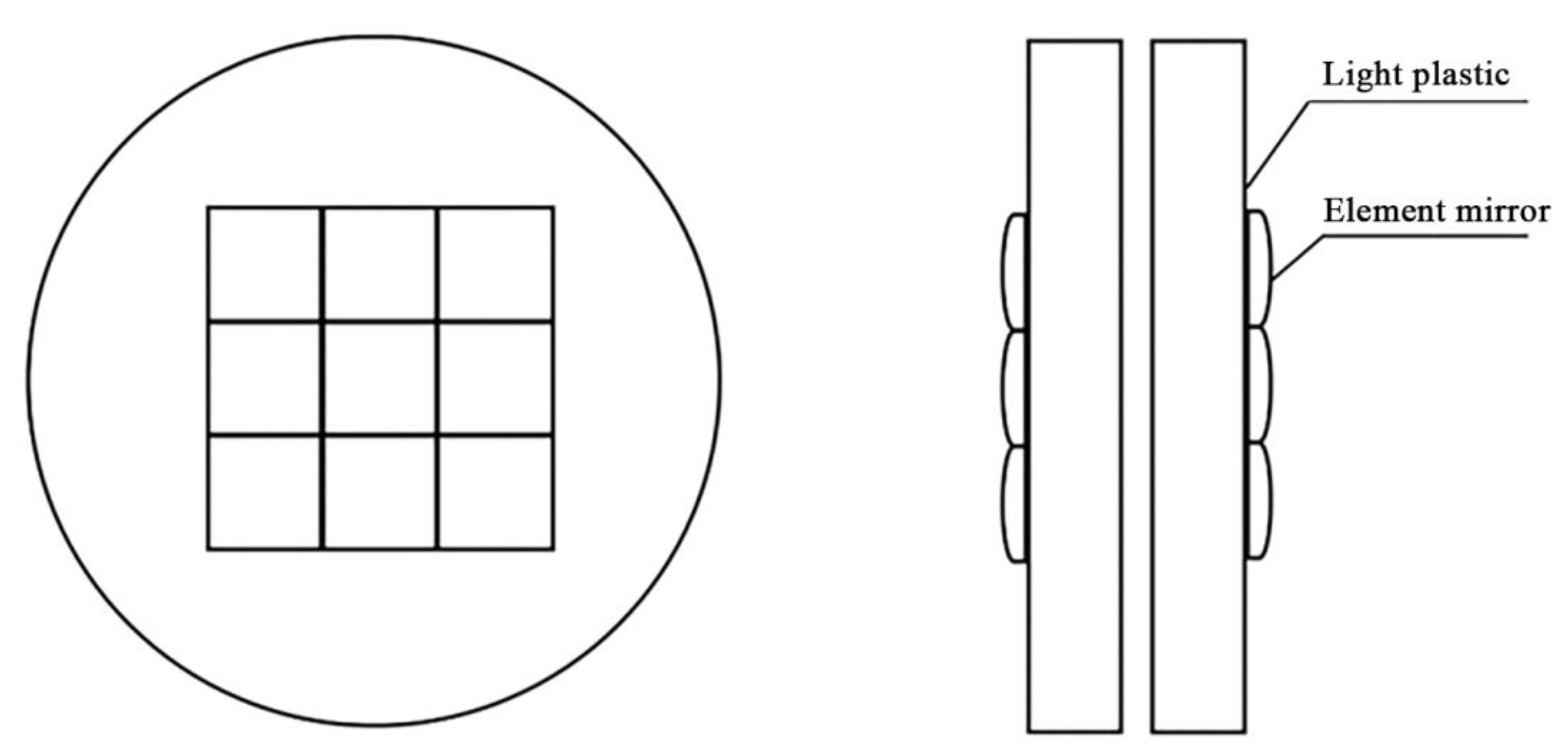
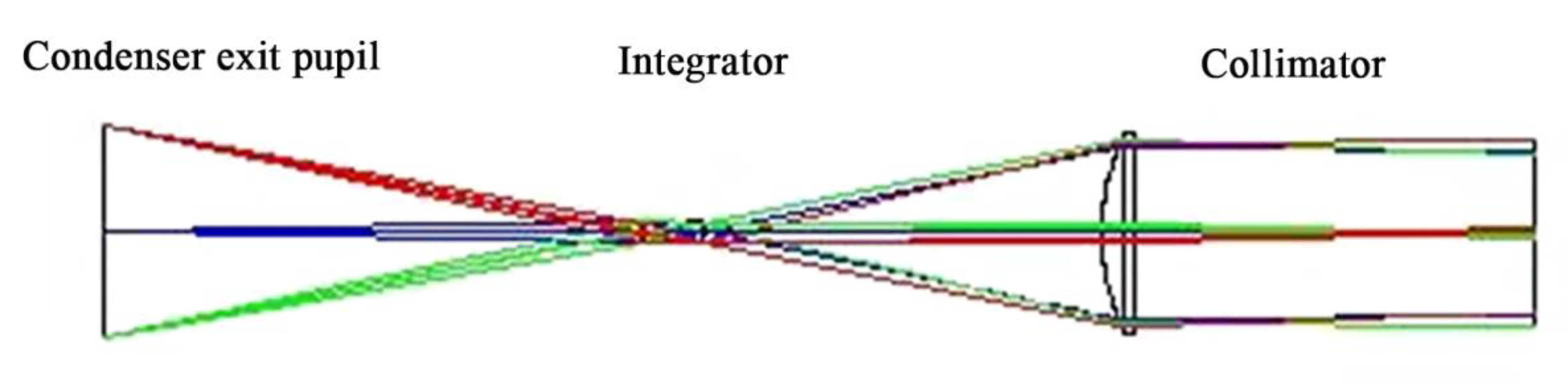
2.1.2. Structure and Working Principle of Near UV Irradiation Device
2.2. Test Verification Method
2.2.1. Material
2.2.2. Experimental Approach
3. Results and Discussion
3.1. Operation Effect Test of Space Ultraviolet Radiation Simulator
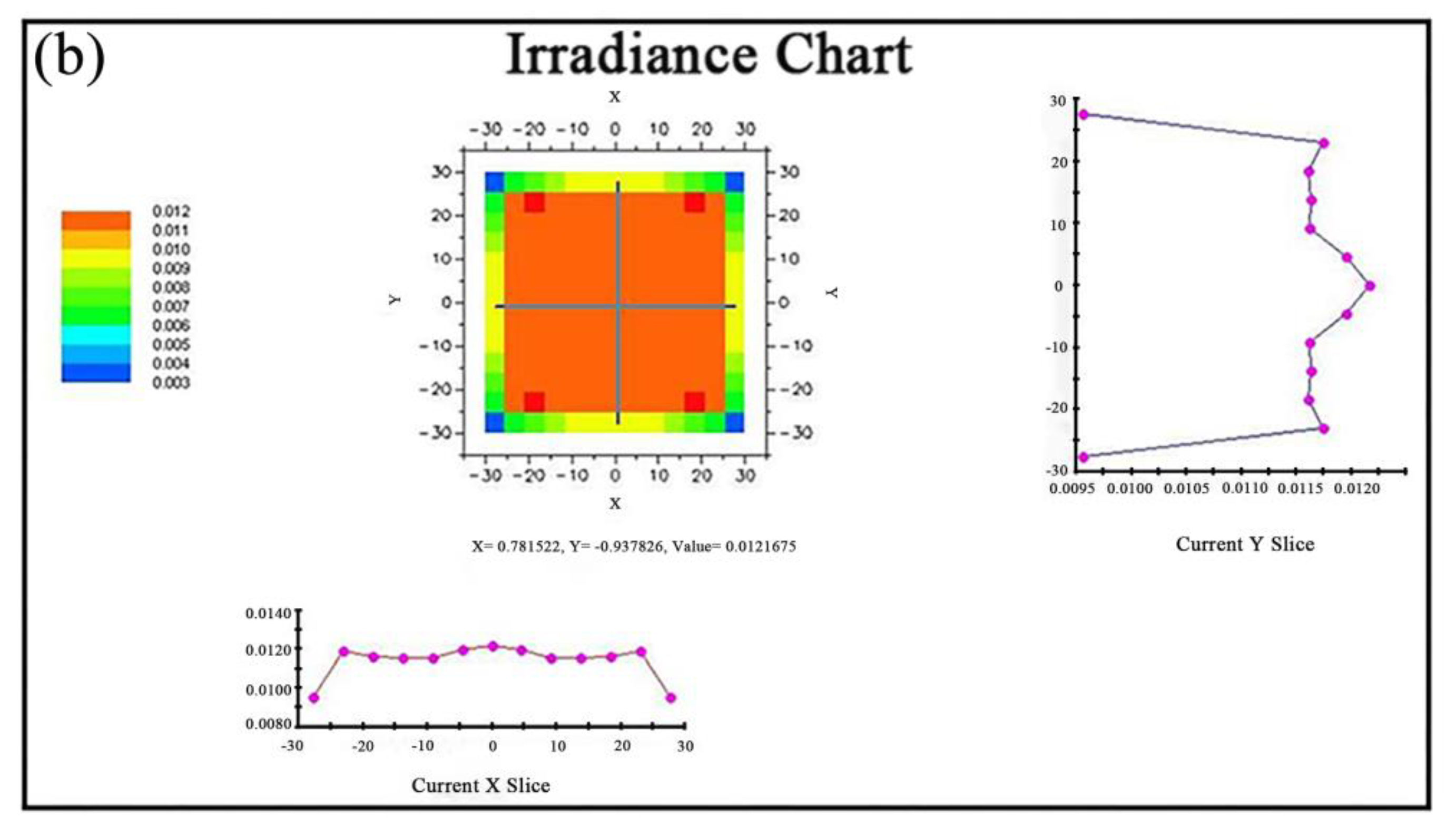
3.1.1. Parameter Test and Calibration of the Whole Space Ultraviolet Radiation Simulation Device
3.1.2. Virtual Operation Effect of Near UV Irradiation Device
3.2. Experimental Validation
3.2.1. Surface Morphology and Microscopic Analysis
3.2.2. XPS Analysis
3.2.3. Mechanical Properties Analysis
3.2.4. Tribological Performance Analysis
4. Conclusions
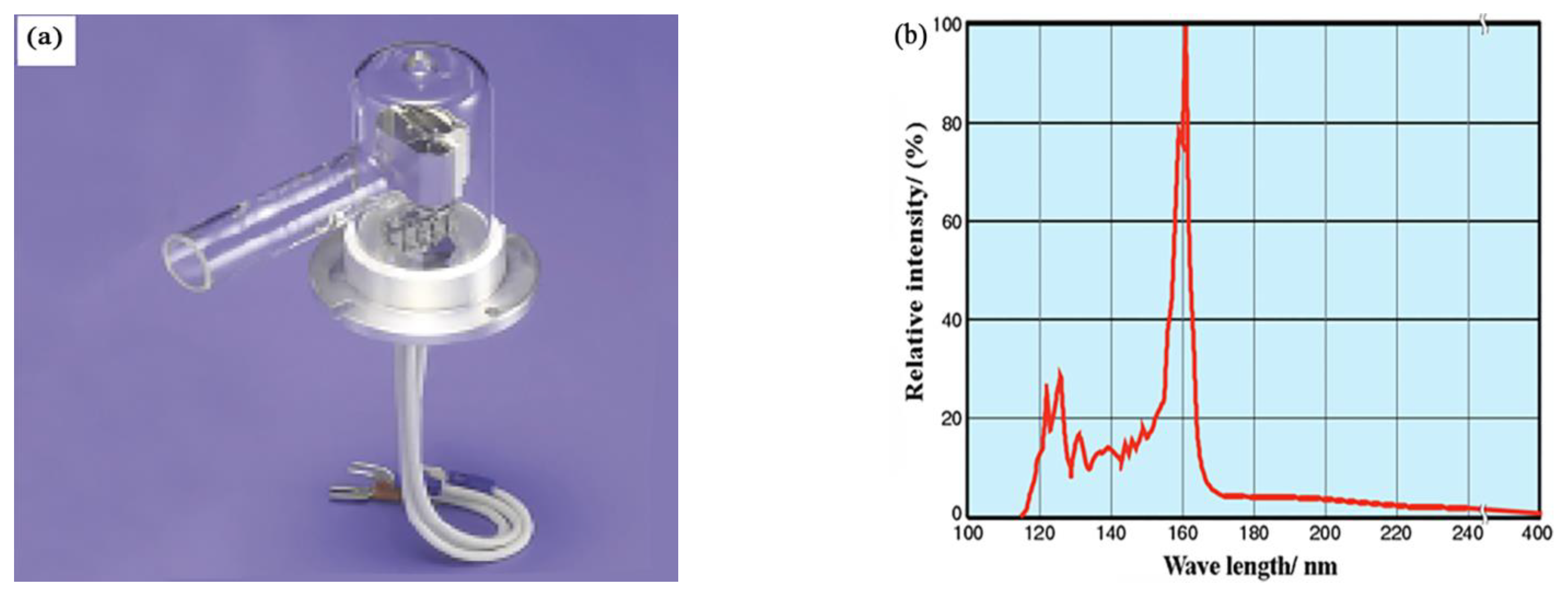
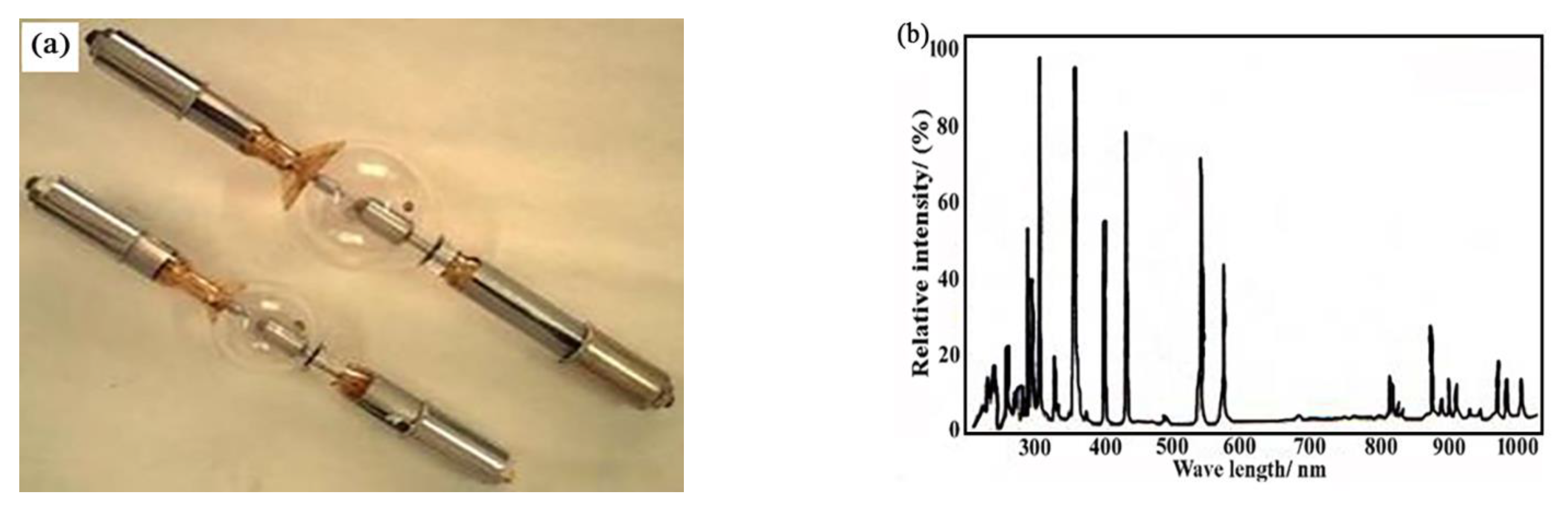
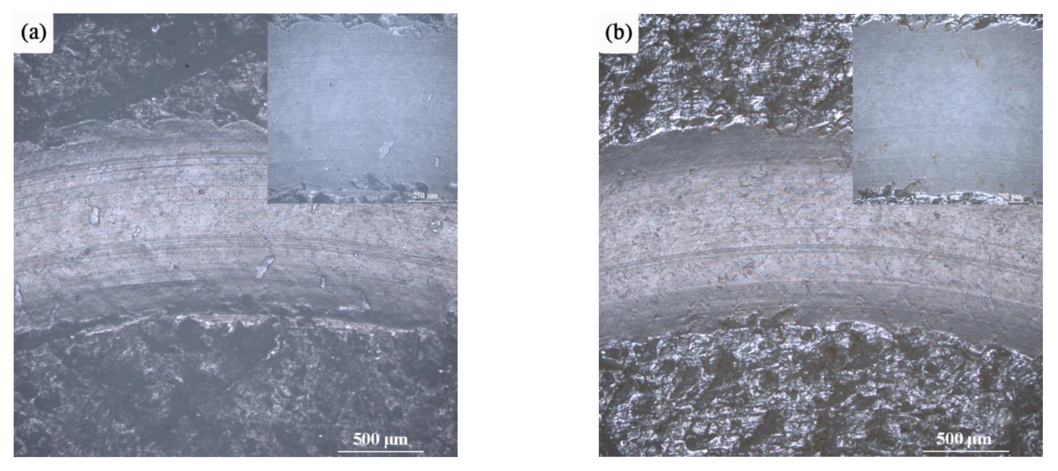
- (a)
- In order to study the tribological properties of lubricating materials under space UV irradiation environment, an in-situ Tribological Testing Machine for simulating space UV radiation on ground conditions was developed. The relevant indexes of the device were as follows: the spectral range was 115~404 nm, average irradiation intensity is 590 W/m2, and the uniform radiation area was 50 mm × 50 mm. Therefore, the device can not only emit high-intensity space ultraviolet rays, but also meet the requirements of in-situ friction performance test.
- (b)
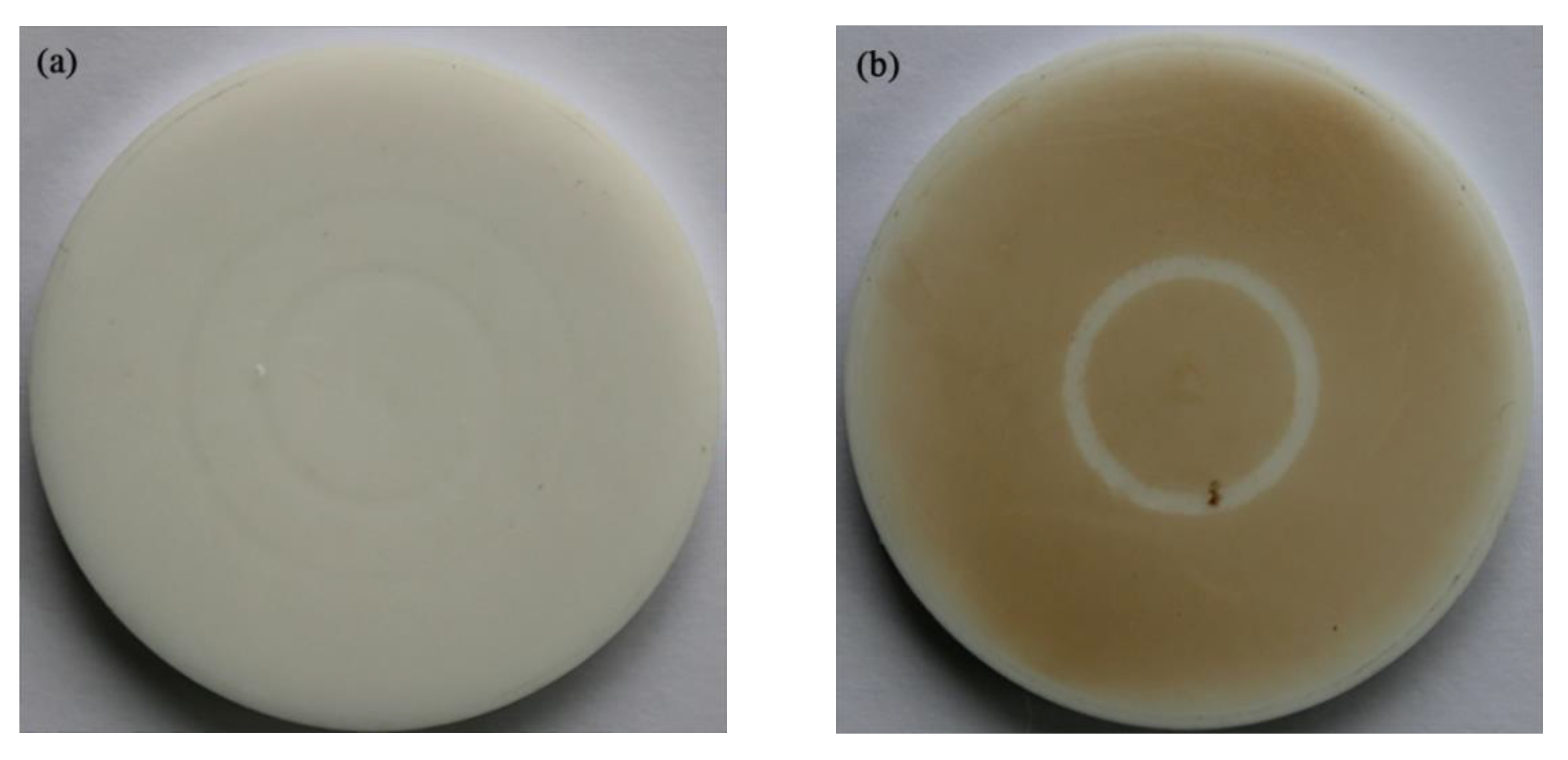
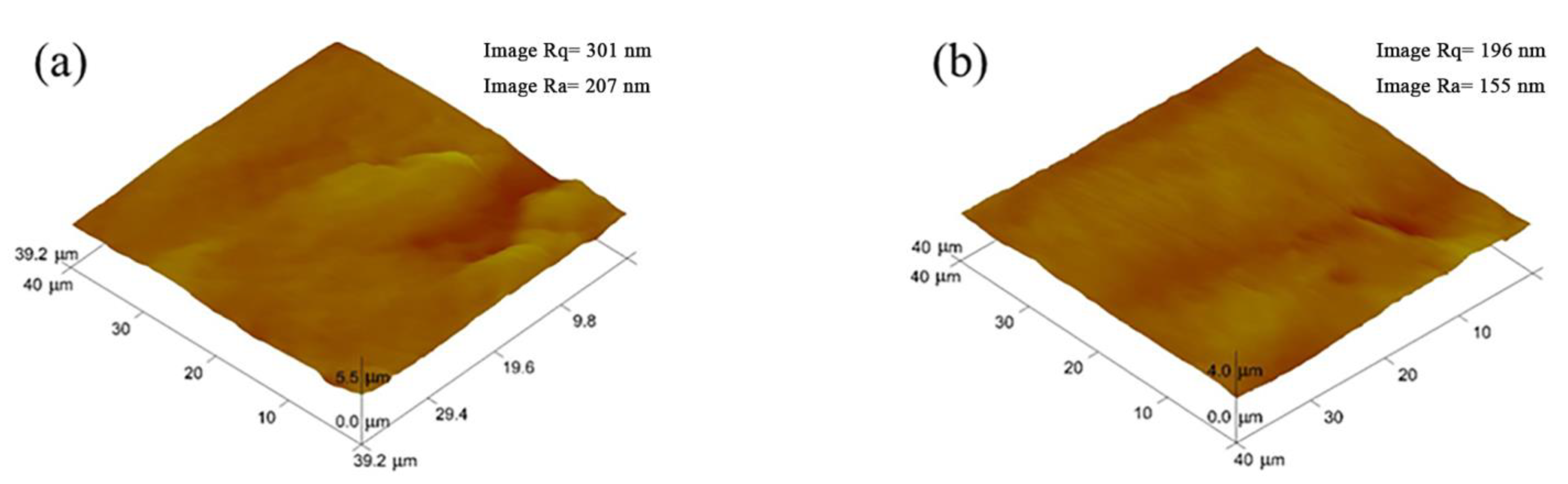
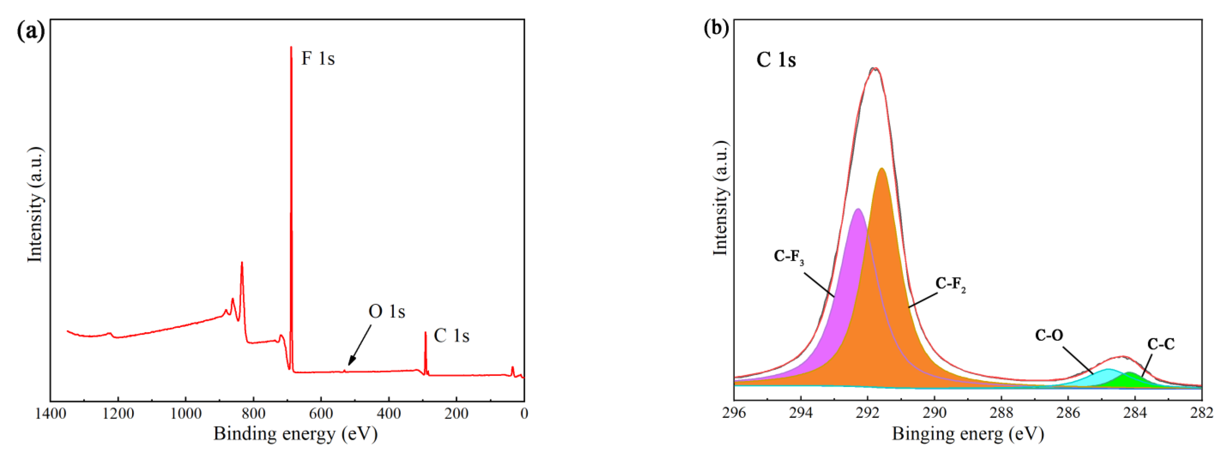
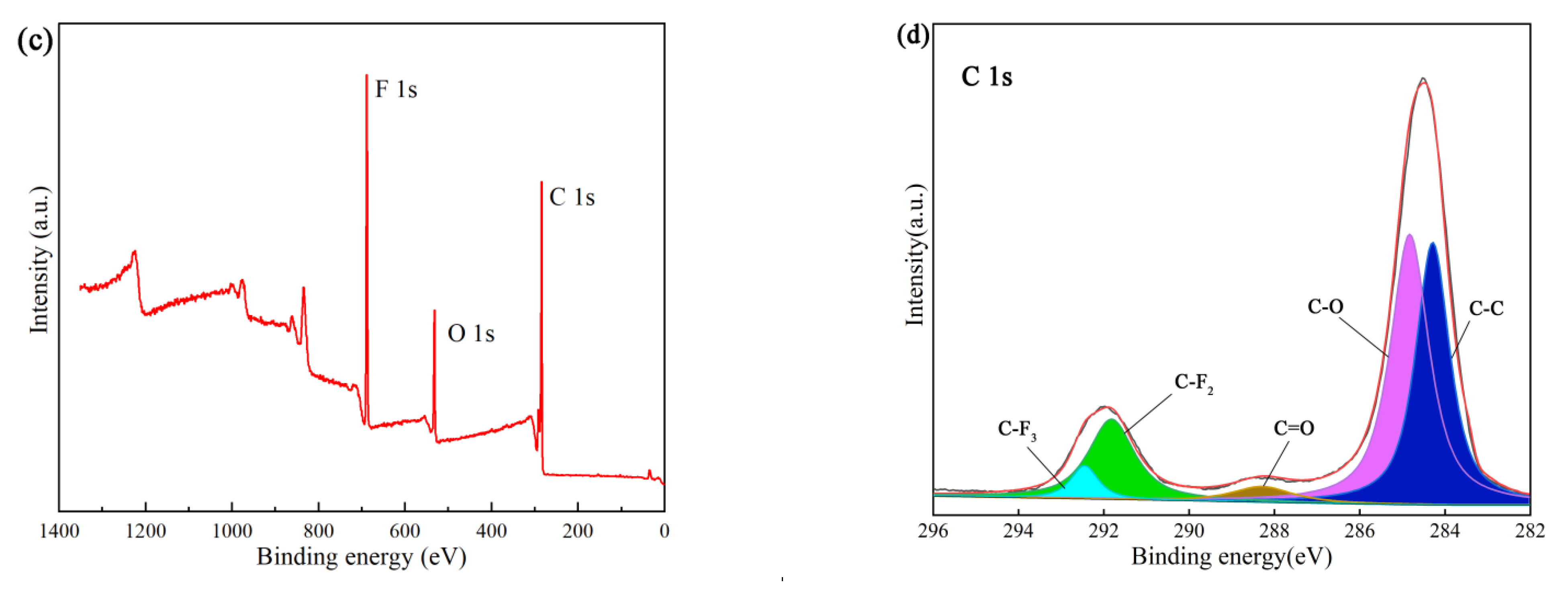
- Through the UV irradiation test of PTFE, which is commonly used as solid lubricating material, the test machine can induce the damage and failure of PTFE material similar to space flight test. After irradiation with high-energy UV photons, some molecular chains on the surface of the sample are broken, and some bonds are recombined. The surface of the sample is carbonized, the color is deepened, and the surface roughness of the sample is reduced.
- (c)
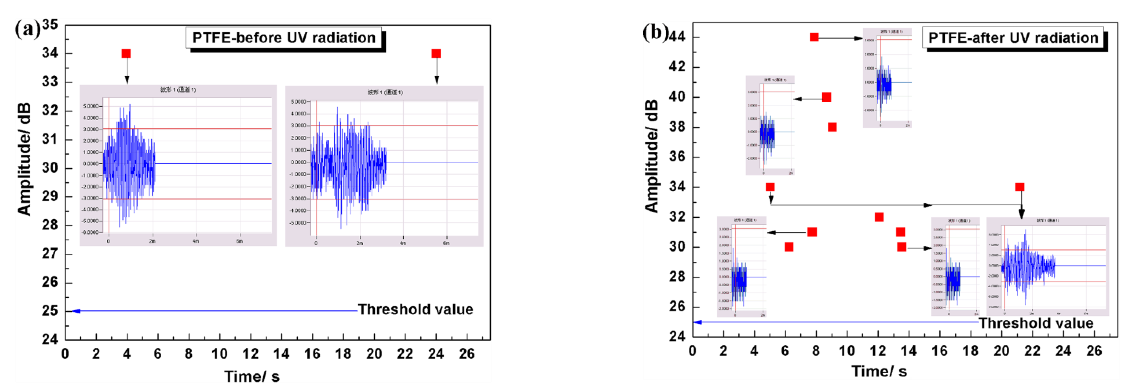
- After UV irradiation, the tribological and mechanical properties of PTFE materials will change. The brittleness of the surface layer of PTFE increases obviously, and the fluctuation range of friction coefficient becomes larger in the process of friction and wear test. However, the action depth of UV irradiation is limited to the surface layer of the sample. After removing the “brittle layer” on the surface of the sample for a period of time, the average value of the friction coefficient during the stable period is not significantly different from that of the unirradiated sample.
Author Contributions
Funding
Institutional Review Board Statement
Informed Consent Statement
Data Availability Statement
Conflicts of Interest
References
- Bhayani, D.; Naik, H.; Nathaniel, T.N.; Khan, S.; Mehta, P. Simulated space radiation: Investigating ionizing radiation effects on the stability of amlodipine besylate API and tablets. Eur. J. Pharm. Sci. 2019, 137, 104982. [Google Scholar] [CrossRef] [PubMed]
- Qin, W.M.; Wang, L.C.; Wei, J.; Hu, B.; Liang, X. A novel efficient broadband model to derive daily surface solar Ultraviolet radiation (0.280–0.400 μm). Sci. Total Environ. 2020, 735, 139513. [Google Scholar] [CrossRef] [PubMed]
- Waszkowska, K.; Chtouki, T.; Krupka, O.; Smokal, V.; Figà, V.; Sahraoui, B. Effect of UV-Irradiation and ZnO nanoparticles on nonlinear optical response of specific photochromic polymers. Nanomaterials 2021, 11, 492. [Google Scholar] [CrossRef] [PubMed]
- Rashad, M.; Darwish, A.A.A.; Qashou, S.I.; El-Rahman, K.F.A. Influence of ultraviolet irradiation on physical properties of nano-NiO films for optical applications. Appl. Phys. A 2020, 126, 862. [Google Scholar] [CrossRef]
- Mariello, M.; Fachechi, L.; Guido, F.; De, V.M. Conformal, ultra-thin skin-contact-actuated hybrid piezo/triboelectric wearable sensor based on aln and parylene-encapsulated elastomeric blend. Adv. Funct. Mater. 2021, 31, 2101047. [Google Scholar] [CrossRef]
- Hazarika, A.; Maji, T.K. Synergistic effect of nano-TiO2 and nanoclay on the ultraviolet degradation and physical properties of wood polymer nanocomposites. Ind. Eng. Chem. Res. 2013, 52, 13536–13546. [Google Scholar] [CrossRef]
- Kemnitz, R.A.; Cobb, R.G.; Singh, A.K.; Hartsfield, R.C. Characterization of simulated low earth orbit space environment effects on acid-spun carbon nanotube yarns. Mater. Des. 2019, 184, 108178. [Google Scholar] [CrossRef]
- Guo, C.; Chen, F.; Wei, B.L.; Zhang, H. Microstructure and tribological properties of a laser clad NiCr-Based composite coating in high vacuum at elevated temperature, atomic oxygen and ultraviolet (UV) irradiation environments. Lasers Eng. 2019, 44, 355–370. [Google Scholar]
- Matsumoto, K.; Tagawa, M.; Akiyama, M. Effev cts of long-term irradiation with LEO environment effective factors on properties of solid lubricant. Trans. Jpn. Soc. Aeronaut. Space Sci. Space Technol. Jpn. 2009, 7, 31–36. [Google Scholar]
- Matsumoto, K.; Tagawa, M.; Akiyama, M. Tribological characteristics of bonded MoS2 film exposed to AO, UV and real LEO environment in SM/SEED experiment. AIP Conf. Proc. 2009, 1087, 148–153. [Google Scholar]
- Tagawa, M.; Yokota, K.; Ochi, K.; Akiyama, M.; Matsumoto, K.; Suzuki, M. Comparison of macro and microtribological property of molybdenum disulfide film exposed to LEO space environment. Tribol. Lett. 2012, 45, 349–356. [Google Scholar] [CrossRef]
- Sugimura, H.; Hayashi, K.; Amano, Y.; Takai, O.; Hozumi, A. Friction force microscopy study on photodegradation of organosilane self-assembled monolayers irradiated with a vacuum ultraviolet light at 172 nm. J. Vac. Sci. Technol. A. Vac. Surf. Film. 2001, 19, 1261–1265. [Google Scholar] [CrossRef]
- Tokoroyama, T.; Kamiya, M.; Umehara, N.; Fuwa, Y. The effect of ultraviolet ray irradiation on CNx coating’s tribological property (micro/nanosystem science and technology i, technical program of oral presentations). In Proceedings of the JSME-IIP/ASME-ISPS Joint Conference on Micromechatronics for Information and Precision Equipment: IIP/ISPS Joint MIPE, Ibaraki, Japan, 17–20 June 2009; pp. 87–88. [Google Scholar]
- Tokoroyama, T.; Hatano, T.; Umehara, N.; Fuwa, Y. The effect of ultraviolet light irradiation on friction property of DLC film. Proc. JSME Annu. Meet. 2010, 8, 229–230. [Google Scholar] [CrossRef]
- Zhang, J.Q. Environmental simulation equipment for space materials and its evaluation. Spacecr. Environ. Eng. 1995, 1, 34–36. [Google Scholar]
- Theiler, G.; Wachtendorf, V.; Elert, A.; Weidner, S. Effects of UV radiation on the friction behavior of thermoplastic polyurethanes. Polym. Test. 2018, 70, 467–473. [Google Scholar] [CrossRef]
- Sun, X.J.; Liu, W.M. Tribological testing technology in simulated space environments. Eng. Test 2009, S1, 24–29. [Google Scholar]
- Ren, J.; Gong, K.L.; Zhao, G.Q.; Lou, W.J.; Wu, X.H.; Wang, X.B. Investigation of the tribological performances of graphene and WS2 nanosheets as additives for perfluoroalkylpolyethers under simulated space environment. Tribol. Lett. 2021, 69, 45. [Google Scholar] [CrossRef]
- Wu, Y.X.; Liu, Y.; Li, H.X.; Chen, J.M.; Yu, S.W.; Zhou, B.; Tang, B. The effect of vacuum atomic oxygen and ultraviolet radiations on Ag/a-C:H nanocomposite film. Tribol. Int. 2016, 101, 395–401. [Google Scholar] [CrossRef]
- Ma, G.Z.; Xu, B.S.; Wang, H.D.; Zhang, S. Development of a novel multifunctional vacuum tribometer. Chin. J. Vac. Sci. Technol. 2013, 33, 162–167. [Google Scholar]
- Yu, C.Y.; Ju, P.F.; Wan, H.Q.; Chen, L.; Li, H.X.; Zhou, H.D.; Chen, J.M. Tribological properties of the polyacrylate/PTFE coating modified by POSS in the space environment. J. Appl. Polym. Sci. 2020, 137, 48730. [Google Scholar] [CrossRef]
- Song, J.F.; Zhao, G.; Ding, Q.J.; Qiu, J.H. Anti-irradiation and wear resistance of polyimide composites. Solid State Phenom. 2017, 267, 253–257. [Google Scholar] [CrossRef]
- Skurat, E.V.; Samsonov, V.P.; Nikiforovpavel, P.A. Vacuum ultraviolet radiation in sources of hyperthermal atomic oxygen. Photodestruction of polytetrafluoroethylene (PTFE) and teflon FEP for hdication of this radiation. High Perform. Polym. 2004, 16, 339–355. [Google Scholar] [CrossRef]
- Yuan, X.D.; Liu, Y.; Yang, D.Z.; He, S.Y. Tribological behavior of polytetrafluoroethylene coatings based on LY12 substrates in the space environment. J. Shanghai Jiaotong Univ. (Sci.) 2014, 19, 636–640. [Google Scholar] [CrossRef]
- Li, C.; Qiao, X.; Wang, T.; Weng, W.X.; Li, Q. Damage evolution and failure mechanism of thermal barrier coatings under Vickers indentation by using acoustic emission technique. Prog. Nat. Sci.-Mater. Int. 2018, 28, 90–96. [Google Scholar] [CrossRef]
- Wang, H.D.; Xu, B.S.; Song, Y.N.; Piao, Z.Y. Coating Bonding Strength Tester for Remanufactured Parts. Patent CN103196824A, 10 July 2013. [Google Scholar]
- Zhang, Z.Q.; Li, G.L.; Wang, H.D.; Xu, B.S.; Piao, Z.Y.; Zhu, L.N. Investigation of rolling contact fatigue damage process of the coating by acoustics emission and vibration signals. Tribol. Int. 2012, 47, 25–31. [Google Scholar]
- Ma, G.Z.; Xu, B.S.; Wang, H.D.; Wan, X.H.; Li, G.L.; Zhang, S. Research on the microstructure and space tribology properties of electric-brush plated Ni/MoS2-C composite coating. Surf. Coat. Technol. 2013, 221, 142–149. [Google Scholar] [CrossRef]
- Drobny, P.; Caplovic, L.; Sahul, M.; Babincova, P.; Koula, V. Acoustic emission analysis of hard coatings cracking during indentation test. IOP Conf. Ser. Mater. Sci. Eng. 2020, 726, 012004. [Google Scholar] [CrossRef]
- Dong, T.S.; Wang, R.; Li, G.L.; Liu, M. Failure mechanism and acoustic emission signal characteristics of coatings under the condition of impact indentation. High Temp. Mater. Processes 2019, 38, 601–611. [Google Scholar]
- Zhao, G.; Liu, B.X.; Wang, Q.H.; Wang, T.M. The effect of the addition of talc on tribological properties of aramid fiber-reinforced polyimide composites under high vacuum, ultraviolet or atomic oxygen environment. Surf. Interface Anal. 2013, 45, 605–611. [Google Scholar] [CrossRef]
- Johnson, M.A.; Cote, P.J. Detrended fluctuation analysis of UV degradation in a polyurethane coating. J. Coat. Technol. 2003, 75, 51–57. [Google Scholar] [CrossRef] [Green Version]
- Fu, C.Q.; He, X.; Wang, Z. Effects of Surfactant Agent and PTFE Content on Surface Morphology and Microstructure of Ni-P-PTFE Composite Coating. Adv. Mater. Res. 2013, 625, 198–201. [Google Scholar] [CrossRef]
- Barylski, A.; Swinarew, A.S.; Aniolek, K.; Kaptacz, S.; Gabor, J.; Stanula, A.; Waskiewicz, Z.; Knechtle, B. Tribological and mechanical behavior of graphite composites of polytetrafluoroethylene (PTFE) irradiated by the electron beam. Polymers 2020, 12, 1676. [Google Scholar] [CrossRef] [PubMed]
- Wang, H.D.; Ma, G.Z.; Xu, B.S.; Xing, Z.G.; Li, G.L.; Zhang, S. The erosion effect of kapton film in a ground-based atomic oxygen irradiation simulator. J. Wuhan Univ. Technol.-Mater. Sci. Ed. 2014, 29, 1277–1282. [Google Scholar] [CrossRef]
- Zhu, L.N.; Wang, C.B.; Wang, H.D.; Xu, B.S.; Zhuang, D.M.; Liu, J.J.; Li, G.L. Microstructure and tribological properties of WS2/MoS2 multilayer films. Appl. Surf. Sci. 2012, 258, 1944–1948. [Google Scholar]


| UV Irradiation Intensity | Spectral Range | Uniform Irradiation Area | Quasi-Right Angle | UV Irradiation Uniformity | UV Irradiation Stability |
|---|---|---|---|---|---|
| 5 UV constants | 115~404 nm | Φ50 mm | Φ50 mm | better than ±10% | better than (5%)/h |
| Design Index | Measured Index | |
|---|---|---|
| Spectral range | 120~400 nm | 115~404 nm |
| Irradiation intensity | 3 UV constants | 6 UV constants |
| Irradiation surface size | ≥Φ50 mm | 50 mm × 50 mm |
| Irradiation inhomogeneity | Better than ±10% | ±5.4% |
| Quasi right angle | Less than 5° | 4° |
| Irradiation instability | Better than (5%)/h | (1%)/h |
| Element | Before Irradiation (at %) | After Irradiation (at %) |
|---|---|---|
| F | 88.87 | 45.04 |
| C | 10.50 | 36.96 |
| O | 0.63 | 18.00 |
Publisher’s Note: MDPI stays neutral with regard to jurisdictional claims in published maps and institutional affiliations. |
© 2022 by the authors. Licensee MDPI, Basel, Switzerland. This article is an open access article distributed under the terms and conditions of the Creative Commons Attribution (CC BY) license (https://creativecommons.org/licenses/by/4.0/).
Share and Cite
Wei, A.; Liu, Q.; Ma, G.; Yu, W.; Shi, J.; Liu, Y.; Han, C.; Li, Z.; Wang, H.; Li, G. Development and Verification Experiment of In-Situ Friction Experiment Device for Simulating UV Irradiation in Space. Materials 2022, 15, 2063. https://doi.org/10.3390/ma15062063
Wei A, Liu Q, Ma G, Yu W, Shi J, Liu Y, Han C, Li Z, Wang H, Li G. Development and Verification Experiment of In-Situ Friction Experiment Device for Simulating UV Irradiation in Space. Materials. 2022; 15(6):2063. https://doi.org/10.3390/ma15062063
Chicago/Turabian StyleWei, Aobo, Qian Liu, Guozheng Ma, Wenbo Yu, Jiadong Shi, Yunfan Liu, Cuihong Han, Zhen Li, Haidou Wang, and Guolu Li. 2022. "Development and Verification Experiment of In-Situ Friction Experiment Device for Simulating UV Irradiation in Space" Materials 15, no. 6: 2063. https://doi.org/10.3390/ma15062063
APA StyleWei, A., Liu, Q., Ma, G., Yu, W., Shi, J., Liu, Y., Han, C., Li, Z., Wang, H., & Li, G. (2022). Development and Verification Experiment of In-Situ Friction Experiment Device for Simulating UV Irradiation in Space. Materials, 15(6), 2063. https://doi.org/10.3390/ma15062063