Article

Concrete by Preplaced Aggregate Method Using Silica Fume and Polypropylene Fibres

by
Farooq Azam Khanzada
1,
Kashif Nazir
2,
Muhammad Ishtiaq
3,
Muhammad Faisal Javed
4,*,
Sardar Kashif-ur-Rehman
4,
Fahid Aslam
5,
Muhammad Ali Musarat
6 and
Kseniia Iurevna Usanova
7
1
Department of Transportation Engineering (SCEE), National University of Sciences and Technology, Islamabad 44000, Pakistan
2
Department of Civil Engineering, School of Engineering, Nazabayev University, Astana 010000, Kazakhstan
3
Department of Civil Engineering, Capital University of Science & Technology, Islamabad 44000, Pakistan
4
Department of Civil Engineering, COMSATS University Islamabad, Abbottabad Campus, Abbottabad 22060, Pakistan
5
Department of Civil Engineering, College of Engineering in Al-Kharj, Prince Sattam Bin Abdulaziz University, Al-Kharj 11942, Saudi Arabia
6
Department of Civil and Environmental Engineering, Universiti Teknologi PETRONAS, Bandar Seri Iskandar 32610, Perak, Malaysia
7
Peter the Great St. Petersburg Polytechnic University, 195291 St. Petersburg, Russia
*
Author to whom correspondence should be addressed.
Materials 2022, 15(6), 1997; https://doi.org/10.3390/ma15061997
Submission received: 10 December 2021 / Revised: 24 December 2021 / Accepted: 25 December 2021 / Published: 8 March 2022

Abstract

:
Preplaced aggregate concrete (PAC) is prepared in two steps, with the coarse aggregate being initially laid down in the formwork, after which a specialised grout is injected into it. To enhance the properties of concrete and to reduce the emission of CO2 produced during the production of cement, supplementary cementitious materials (SCMs) are used to partially substitute ordinary Portland cement (OPC). In this study, 100 mm × 200 mm (diameter x height) PAC cylinders were cast with 10 per cent of cement being substituted with silica fume; along with that, 1.5% dosage of Macro polypropylene fibres were also introduced into the coarse aggregate matrix. Compressive strength test, splitting tensile strength test, mass loss at 250 °C, and compressive strength at 250 °C were performed on the samples. PAC samples with 10% of cement replaced with Silica Fume (SPAC) were used as control samples. The primary objective of this study was to observe the effect of the addition of Polypropylene fibres to PAC having Silica fume as SCM (FRPAC). The aforementioned tests showed that FRPAC had a lower compressive strength than that of the control mix (SPAC). FRPAC had greater tensile strength than that of NPAC and SPAC. Mass loss at 250 °C was greater in SPAC compared to FRPAC. The compressive strength loss at 250 °C was significantly greater in FRPAC compared to SPAC. FRPAC exhibited a greater strain for the applied stress, and their stress-strain curve showed that FRPAC was more ductile than SPAC.

1. Introduction

First introduced in the 1930s, preplaced aggregate concrete (PAC), otherwise called two-stage concrete [1,2], as the name suggests, is prepared in two steps. Initially, clean, gap-graded coarse aggregate is packed within the formwork then, a specialised grout of sufficient flowability is used to fill the openings and voids in the coarse aggregate matrix. Usually, admixtures are added to improve the properties of PAC, especially workability [3,4]. On the contrary, conventional concrete is prepared by mixing all the components and then placing that mix in the formwork. PAC has greater coarse aggregate content, accounting for 60% to 70% of the total volume. While in conventional concrete, the coarse aggregate content takes up only 40% to 50% of the total volume [5,6]. Therefore, the shrinkage in PAC is far less than that of conventional concrete [7]. Furthermore, PAC has a more dense matrix having greater strength as a result of higher pressure and point-to-point contact of the coarse aggregate particles [8]. Along with that, PAC’s production cost is 25% to 40% less than that of conventional concrete [3].
PAC has several uses, which include the construction of concrete structures underwater [4], repair work of pre-built concrete structures [9], mass concreting [10], construction of nuclear power plants [7], and structures involving complex reinforcement [9]. Since its development, PAC has been used in numerous projects throughout the world, for example, in the Pre-facing of Barker Dam at Nederland, Colorado in 1946 [11], in the Scroll case at Bull Dam Powerhouse in 1951 [7], and in Auxiliary dam located in China in 2006 [12]. As PAC has more coarse aggregate and lesser cement content, the demand for cement may be reduced. Moreover, the heat of PAC’s hydration is less than conventional concrete [10]. Therefore, PAC might be considered an eco-friendly alternative to conventional concrete. Another way of further reducing the cement content within PAC is by utilising waste supplementary cementitious materials (SCMs). They improve the durability and mechanical properties of concrete [13]. Efficient use of these SCMs may not only prove to be more eco-friendly and more economical but the carbon footprint of concrete would also be reduced [5]. SCMs include Silica fume (SF) and ground granulated blast furnace slag (GGBFS) [3].
Silica fume is a very fine and highly pozzolanic material with high silica content. Partial substitution of cement with SF has shown enhanced durability, chemical properties, and strength, but the mix’s workability was reduced [5,14]. Silica fume plays the role of a micro filler between the fine aggregate and cement particles, meanwhile increasing the water demand because of its very large surface area, subsequently causing the workability of the grout to decrease [14]. Silica fume reacts with Calcium Hydroxide, leading to greater amounts of Calcium Silicate Hydrate, which is the key factor in the strength development of concrete [13].
Concrete, which mainly suffers from lower tensile strength and higher rigidity, is termed as a brittle material [15,16,17]. However, higher strength and better durability are essential for the aforementioned uses of PAC; for this purpose, additional components are added to PAC to enhance its properties, especially strength and durability. One of the possible components to enhance the properties of concrete are fibres, which may be added in varying dosages. Fibres are used to replace the conventional reinforcement in concrete, either partially or completely, for example, in road pavements, slabs, beams, industrial floors, and tunnel linings [18,19]. The single critical shear crack formation could be avoided, and the occurrence of the shear failure mechanism could be delayed with the inclusion of fibres [20]. Fibres are especially useful in the structural members in which the installation of transverse reinforcements is either difficult or impossible [21,22]. A major benefit of using fibres in concrete is that it increases the toughness of the concrete; subject to any type of loading, the strain corresponding to the peak load is increased, and higher energy absorption is observed in the post-peak portion of the load-deflection curve [23]. Steel fibres are most commonly used [18], accounting for almost half of the total tonnage used [24]. Steel fibres increase the pre and post-cracking tensile strength of the concrete and allow for enhanced crack control [25]. Post-failure inspection of steel-fibre-reinforced concrete shows that the cracking pattern is more widely distributed, and there is a lesser separation between cracks [26]. Various researchers have undergone several studies to enhance the ductility of concrete by using steel fibres [27]. Steel fibres enhance the flexural strength, compressive strength, and modulus of elasticity of concrete [24]. Another type of fibre that may be used is Basalt fibre, obtained from Basalt rocks melted at 1400 °C. These fibres are non-toxic, environmentally friendly, and have high insulating properties [28,29]. The inclusion of Basalt fibres slightly improved the compressive strength of concrete at 28 days of curing. It also enhanced the concrete’s modulus of rupture and flexural strength [30]. Polyethylene terephthalate (PET) strings, a polyester polymer [31], are industrially cut, forming short, multifilament fibres, with a diameter of 30 micrometres, to be used in concrete for the sustainable development of concrete structures [32]. PET fibres enhance the ductility, tensile and compressive strengths, and thermal resistance of concrete [33]. Glass fibres reduce the fresh density of concrete and increase the split tensile strength, compressive strength, flexural strength, porosity, and chloride penetration of concrete [34]. Flax fibres, a bio-based material obtained from plants due to their environmentally friendly nature, are used in concrete for the sustainable development of the concrete industry [35]. These fibres tend to decrease the workability and compressive strength of the concrete. The inclusion of flax fibres in concrete leads to an increase in the air content of fresh concrete, whereas porosity and flexural strength of the concrete also increase [36].
According to previous studies, on the addition of Macro Polypropylene fibres (PP) to conventional concrete, its flexural strength, ductility, and durability were improved, while brittle failure, corrosion of steel reinforcement, plastic, and drying shrinkage in the concrete were reduced [15,33,37,38]. Macro PP fibres may be used to obtain the same level of reinforcement as that of steel, at a cost almost half of that of steel. Along with that, the labour cost was also reduced [39]. On the other hand, using Micro PP fibres in concrete enhances the durability of concrete while the shrinkage cracks are controlled [40]. The reinforcement of concrete with Micro PP fibres have a minimal effect on the concrete’s flexural and compressive strength [41].
This research intends to study the effect of the addition of PP fibres on the mechanical properties and durability of PAC having Silica fume as a partial replacement of cement (SPAC). First, an appropriate mix design for SPAC was decided. After that, SPAC was cast with three types of PP fibres, namely, Mono PP, Fibrillated PP, and Macro PP fibres, each with dosages of 1% and 1.5% (of the total volume of the mix); the optimum fibre type and dosage were determined based on highest compressive strength. The consequent concrete samples were tested for compressive strength, splitting tensile strength, mass, and compressive strength loss at 250 °C and the stress-strain curve was also obtained. A superplasticiser dosage of 1% (by weight of binder) was used throughout this study.

2. Materials and Methods

2.1. Materials

During this research, Cherat Cement was used, which is a Type I ordinary Portland cement (OPC), as per ASTM C 150-2007. The cement had a fineness value of 93.27% and a specific surface area of 267 m2/kg. The cement was obtained from a local supplier at College Road, Abbottabad, Pakistan. Silica fume was procured from Imporient Chemicals (PVT) limited, Islamabad, Pakistan. The specific surface area of the procured Silica fume was noted to be 14,000 m2/kg. An X-ray fluorescence test was carried out on the acquired sample of Silica fume in the ‘National centre of excellence in Geology’, University of Peshawar, Peshawar, Pakistan. The result of the XRF test is shown in Table 1.
Uncrushed river sand was used as the fine aggregate in this research. It was initially sieved through ASTM sieve number 14 before being used. The specific gravity of the fine aggregate was 2.71, with 0.68% water absorption and a fineness modulus of 2.62. The applied stresses are initially transferred to the coarse aggregate skeleton and then to the hardened grout in PAC. Thus, the use of appropriate shape, size, and quality of coarse aggregate need proper consideration [2]. ACI 304.1R-1997 recommends that the coarse aggregate used in PAC must first be washed to remove the dust on the surface to ensure better bonding with the injected grout. The coarse aggregate used was crushed granite with sizes ranging from 19.5 to 38 mm. The water absorption and specific gravity of the coarse aggregates used was 0.54% and 2.74, respectively. Both the fine aggregate and coarse aggregate were brought from a local quarry in Abbottabad. The gradation curves for coarse and fine aggregates are shown in Figure 1 and Figure 2, respectively. Chemrite AG-300, a 3rd generation superplasticiser, was used at a dosage of 1% to improve the flowability of the grout. Three types of polypropylene (PP) fibres, namely Mono, Macro, and Fibrillated PP fibres, were procured from Maxwell company, Karachi, Pakistan. The general characteristics of the procured PP fibres are mentioned in Table 2.

2.2. Mix Proportions

First, various mix designs, as shown in Table 3, were cast to determine the optimum mix design of preplaced aggregate concrete without any replacement or fibres (NPAC). Mix # 24 was selected as the optimum mix for NPAC. Afterwards, several mix designs were cast to determine the optimum mix design of the preplaced aggregate concrete with cement being partially substituted with Silica fume (SPAC), shown in Table 4. Mix # 4 was selected as the optimum mix for SPAC. Subsequently, different mix designs containing varying dosages of fibres were cast to determine the optimum mix design for the Polypropylene fibre-reinforced preplaced aggregate concrete with Silica fume partially substituting cement (FRPAC). The mix designs used are shown in Table 5. Mix # 17 was selected as the optimum mix for FRPAC. For determining the optimum mix designs of NPAC, SPAC, and FRPAC, the mix with the most suitable flowability and the maximum three-day compressive strength was used. Lastly, the final mix designs, as shown in Table 6, were cast, and the respective tests were performed on them. The optimum mix designs determined for NPAC were used as the starting mix design in the trials for determining the optimum mix design of SPAC. Likewise, the optimum mix design of SPAC was used as the initial mix design used for determining the optimum mix design of FRPAC. The mix design used for the final casting of NPAC, SPAC, and FRPAC was the optimum mix design determined for FPRAC.
A cast sample in which the grout was too thick is shown in Figure 3a, a sample in which the flowability of grout is too high is shown in Figure 3b, and a sample with sufficient workability is shown in Figure 3c.

2.3. Sample Preparation

The PAC samples were prepared in two steps. First, the coarse aggregate and PP fibres (in the case of FRPAC) were dry mixed for 2 min and then placed in the formwork. Secondly, the specialised grout was poured into the coarse aggregate matrix using a pipe and funnel, where the flow of grout was due to gravity (gravity method). In this research, cylindrical samples of 100 mm × 200 mm (diameter × height) were used; the cylindrical moulds had a flat base with an opening at the top, from where the aggregates were placed, and the grout was injected. Figure 4 illustrates the mechanism of the pumping of the grout in the preplaced aggregate concrete [42].
The grout, a mixture of cement, Silica fume (in case of SPAC and FRPAC), fine aggregate, water, and superplasticiser, were prepared in an electric mixer. The contents were initially dry mixed for 3 min and then wet mixed for 5 min, with the electric mixer set at high revolutionary speeds to reduce the settlement of sand in the mix and to obtain a uniform and consistent mix. For the gravity method, a pipe of 40 mm diameter was used through which the grout was injected into the cylindrical moulds, as shown in Figure 4. With the pipe inserted in the cylindrical moulds, to the bottom of the mould, a funnel was attached to the top of the pipe through which the grout was slowly poured into the pipe. As the grout was being poured into the top, the pipe was simultaneously removed very slowly. This was performed so that the grout may spread evenly throughout the height of the sample and also to ensure that the pipe does not get choked with the grout. During the injection of grout, special care was taken to ensure that the grout did not leak out of the mould. After the casting was completed, the top surface was finished off to get a smooth surface and then the cast samples were cured at room temperature for 24 h. Subsequently, at the end of the 24 h, the samples were demoulded and then placed in a water tank for a maximum of 28 days.

2.4. Testing Methods

The flowability of the prepared grout was tested using a flow table and conical mould [1,43,44], as shown in Figure 5a. The conical mould was filled with the grout [Step 1 in Figure 5a], then the mould was quickly lifted [Step 2 in Figure 5a], and the spread of the grout was measured using a measuring tape [Step 3 in Figure 5a]. The dimensions of the mould are illustrated in Figure 5b [43].
Cylindrical samples of 100 mm × 200 mm were prepared, cast, and tested as per ASTM C39M-18, and ASTM C496M-17, for compressive strength and splitting tensile strength, respectively. The 100 mm × 200 mm samples, at 28 days of curing, were placed in a Universal Testing Machine (UTM), at COMSATS University Islamabad, Abbottabad campus, Pakistan, to determine the stress-strain relationship of the samples.
The cylindrical samples, with 100 mm diameter and 200 mm height, at 28 days of curing were initially weighed and then placed in an oven at a temperature of 250 °C for 24 h. Finally, after 24 h, the samples were again weighed, and the mass difference was recorded. The samples were also tested for compressive strength, and the strength loss due to high temperature was determined.

3. Results and Discussion

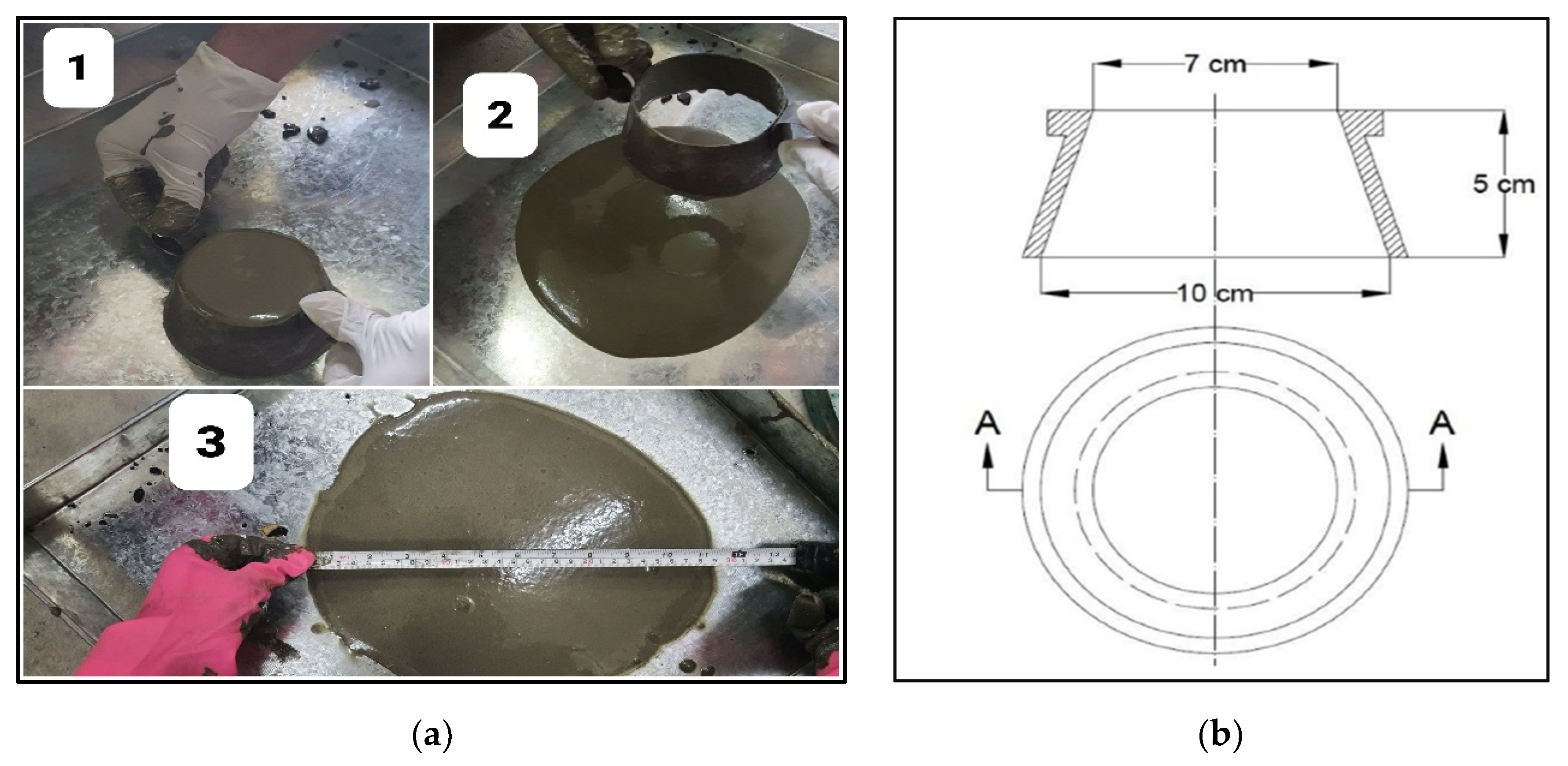
3.1. Flowability of Grout

In PAC, sufficient flowability of the grout is crucial for the successful casting of the concrete. Otherwise, the grout might not penetrate some voids, subsequently leading to honeycombing. Yousefi Oderji et al. used a conical mould to determine the flowability of the grout [38]. The same method was followed in this study, as shown in Section 2.4, to determine the flowability of the prepared grout. It was found that for our 100 mm × 200 mm moulds, a flowability of approximately 280 mm was found to be the optimum value for NPAC and SPAC, as it led to a more acceptable casting of those mixes. However, when PP fibres were added along with the coarse aggregate into the mould, honeycombing was witnessed in the cast samples. Thus, trial and error established that for FRPAC samples, a grout flowability of 356 mm was the optimum value. Assessing the effect of Silica fume on the flowability of the grout, it is evident from Table 4, that higher Silica fume contents led to lower flowability values. Thus, greater water-to-binder (w/b) ratios were required to obtain optimum flowability, with the other parameters being the same. From Table 5, it is evident that higher w/b ratios were required for the successful casting of the mix. It may be because the addition of PP fibres in the mould impeded the spread of grout in the fibre and coarse aggregate skeleton. Thus, higher flowability was required, which was achieved by increasing the w/b ratio.

3.2. Compressive Strength

The results of the compressive strength of NPAC, SPAC, and FRPAC are displayed in Figure 6. Partially replacing cement with Silica fume improved the compressive strength of the cast samples. The increase in compressive strength can be attributed to the higher pozzolanic activity of silica fume. Along with that, the high fineness of Silica fume strengthens the microstructure by improving the particle packing density [14]. It is evident from Figure 6 that the inclusion of PP fibres into SPAC decreased the compressive strength. The strength loss at 28 days of curing was 17.61% compared to SPAC. The loss in compressive strength might be due to the existence of cavities in the matrix produced as a result of the addition of fibres in the mix. Increasing fibre content leads to balling effect, clustering, and the formation of voids, subsequently decreasing the concrete’s strength while also making it more susceptible to cracking. The presence of fibres impedes the spread of grout in the coarse aggregate skeleton, thus reducing compressive strength [45].

3.3. Splitting Tensile Strength

The splitting tensile strength test was conducted on 100 mm × 200 mm cylindrical samples. The results of those tests are shown in Figure 7. As compared to NPAC, SPAC is seen to have a greater splitting tensile strength; the strength difference was 22.3% at 28 days. As evident from Figure 7, the addition of PP fibres led to an increase in the splitting tensile strength of the cast samples. FRPAC had 37% and 18.9% higher splitting tensile strength values than NPAC and SPAC at the age of 28 days, respectively. This improvement in the tensile strength of FRPAC samples, under indirect tension, may be due to the crack arrestment property of the fibres. Greater dosages of PP fibres restricts the formation of cracks in the cast samples; therefore, enhancing the splitting tensile strength of FRPAC [8].

3.4. Mass Loss and Compressive Strength Loss at 250 °C

The FRPAC samples at 28 days of curing were air-dried and then weighed. Afterwards, the samples were placed in an oven at a temperature of 250 ± 5 °C, for 24 h. After 24 h, these samples were taken out of the oven and then, after cooling, were weighed again. The mass loss was calculated by subtracting the mass after heating from the mass before being placed in the oven. It was observed that the mass loss in SPAC samples was 30% greater than that of FRPAC samples, as shown in Figure 8.
The aforementioned samples were then placed in a compression testing machine to determine their post-heating compressive strength. Both FRPAC and SPAC experienced a loss in compressive strength after heating. However, FRPAC samples underwent a substantial loss in compressive strength, approximately 56.6%, compared to just 23.6% in SPAC samples. The results of compressive strength both before and after heating are illustrated in Figure 9. The greater strength loss might be due to the melting of PP fibres at 160 to 170 °C, which leads to microcracks and greater porosity, thus decreasing the strength of concrete [46].

3.5. Stress-Strain Relationship

FRPAC and SPAC samples, after 28 days of curing, were placed in a UTM to determine the stress-strain relationship of both mixes. Three samples each for SPAC and FRPAC were tested. Due to the overlapping of the curves, only one of the curves for each SPAC and FRPAC was used in Figure 10. As illustrated in Figure 10, FRPAC achieved greater strain values for given applied stress compared to SPAC. Thus, referring to the stress-strain plot, it can be said that the addition of PP fibres in the mix leads to an enhancement in the ductility of the concrete.

4. Conclusions

This study was undertaken to observe the influence of the inclusion of Polypropylene (PP) fibres in preplaced aggregate concrete (PAC) with cement being partially replaced by Silica fume. PAC without Silica fume or PP fibres (NPAC), PAC with Silica fume as supplementary cementitious material (SPAC), and PP fibre-reinforced SPAC (FRPAC) were tested at 3, 7, and 28 days of curing. Compressive strength test, splitting tensile strength test, mass loss, and compressive strength test at 250 °C were performed on the samples. After thoroughly analysing the results, it was concluded that:
  • SPAC had higher compressive strength than NPAC; the difference in strength was noted to be 22.6% at 28 days. This may be attributed to higher pozzolanic activity and high sample density due to the addition of Silica fume.
  • The inclusion of fibres in SPAC led to a reduction in the compressive strength of the cast samples. At 28 days of curing, FRPAC had 17.61% lower compressive strength than SPAC. The loss in compressive strength might be due to the generation of a greater number of voids in the cast samples due to the addition of fibres. Furthermore, higher fibre dosages inhibit the flow of grout in the coarse aggregate skeleton.
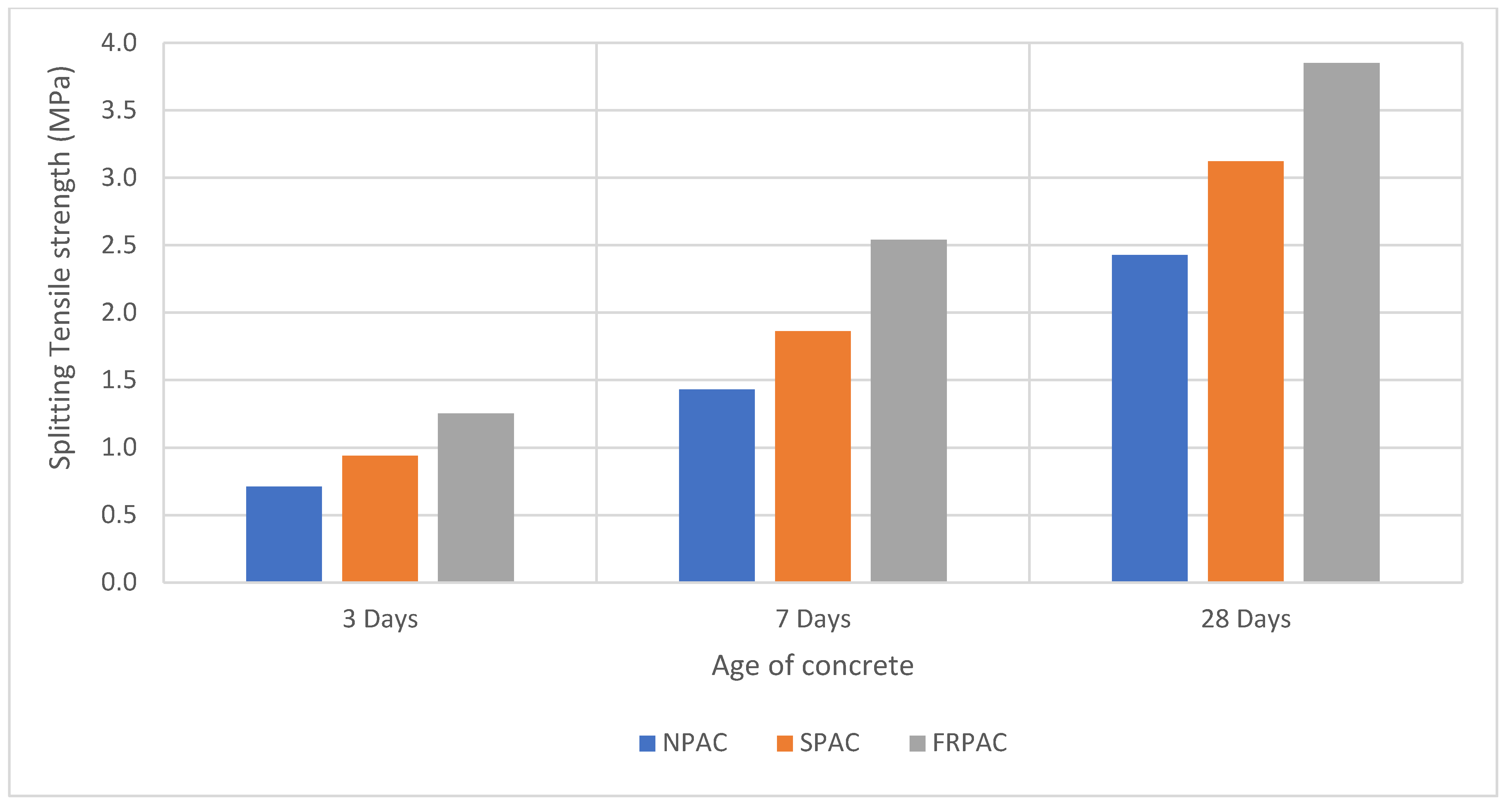
  • Overall, FRPAC had the highest splitting tensile strength among the three mixes. At the age of 28 days, FRPAC had 37% and 18.9% higher splitting tensile strength values than NPAC and SPAC, respectively. It is evident that the inclusion of PP fibres enhances the deformation capacity of preplaced aggregate concrete. It may be mainly due to the bridging action of the fibres, preventing the formation and spread of microcracks.
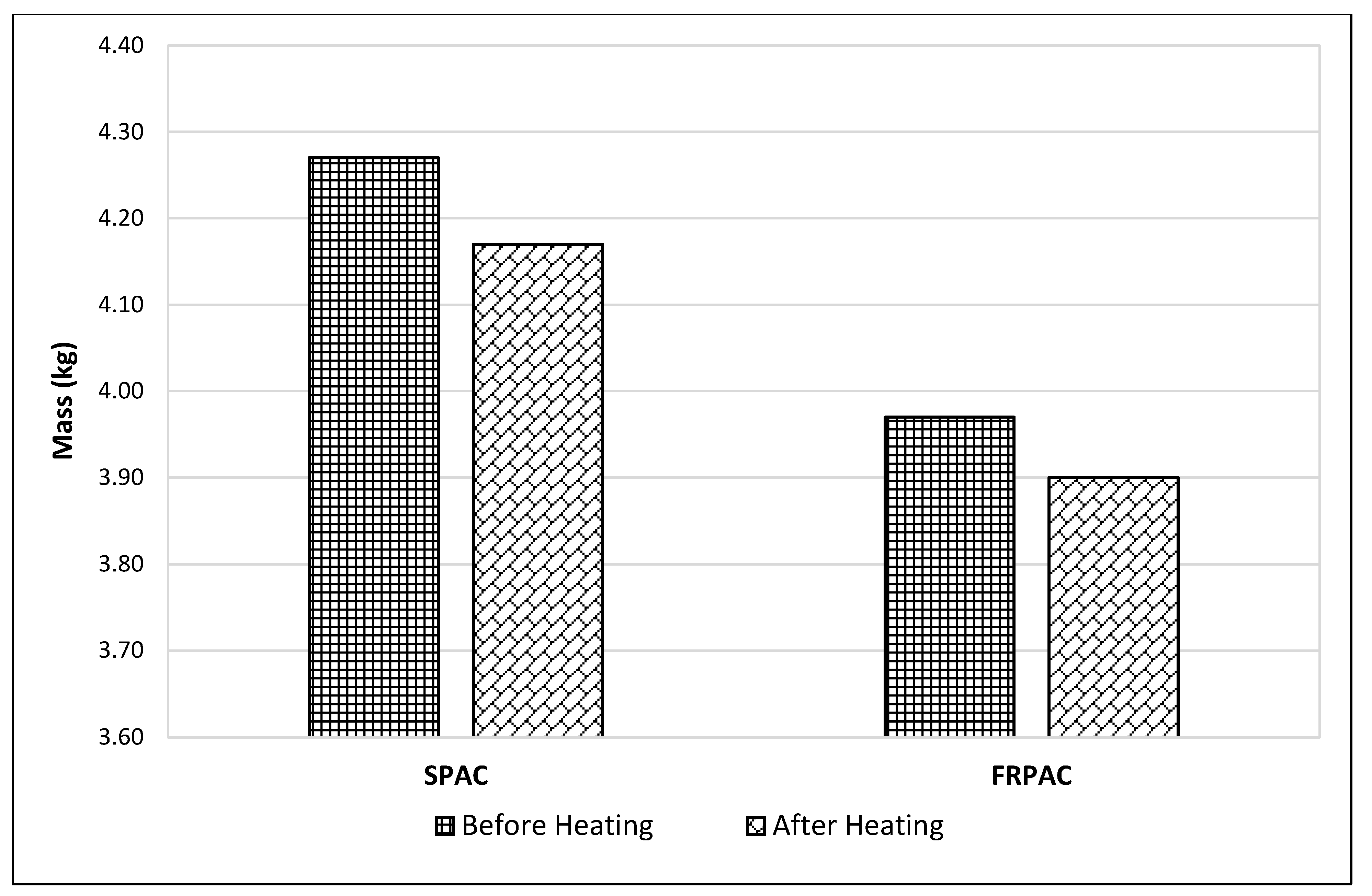
  • The mass loss in SPAC at 250 °C was 30% greater than that of FRPAC. SPAC suffered a mass loss of 2.34% as compared to 1.76% in FRPAC.
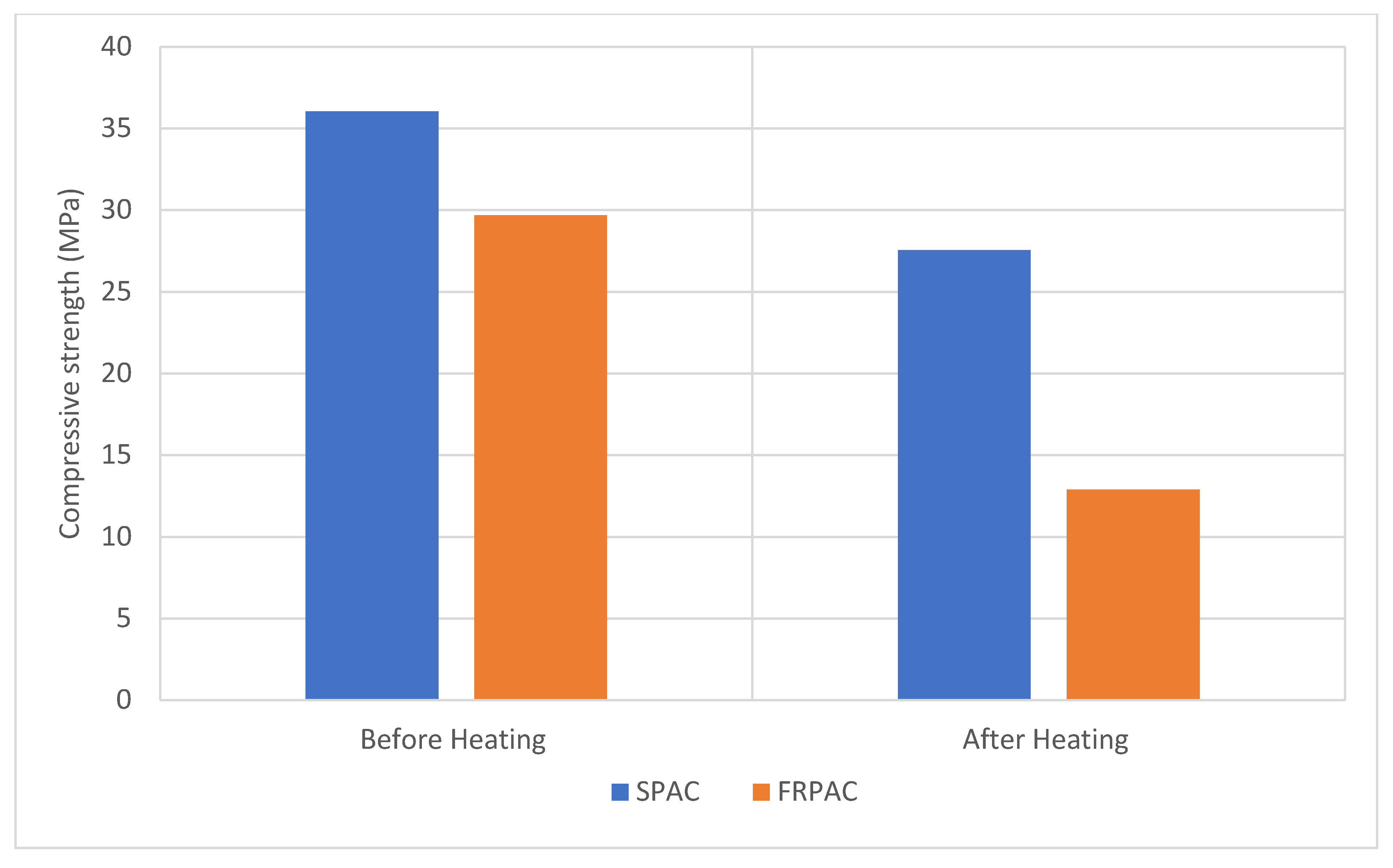
  • The compressive strength loss at 250 °C was considerably greater in FRPAC compared to SPAC. SPAC suffered a compressive strength loss of 23.6% compared to 56.6% in FRPAC.
  • Stress-strain curves of FRPAC and SPAC showed that FRPAC exhibited greater strain for the amount of stress applied. Hence it could be deduced from these curves that the inclusion of Polypropylene fibres imparted ductile properties in concrete.

Author Contributions

Supervision, review, and editing, F.A.K., K.N. and M.I.; data curation and methodology, F.A.K., M.I. and S.K.-u.-R.; investigation and review, K.N., S.K.-u.-R. and M.F.J.; conceptualization, data analysis, writing original draft preparation, M.F.J. and M.A.M.; formal analysis and modeling, F.A.; validation, proofreading, review, M.A.M. and K.I.U. All authors have read and agreed to the published version of the manuscript.

Funding

The research was partially funded by the Ministry of Science and Higher Education of the Russian Federation under the strategic academic leadership program ‘Priority 2030’ (Agreement 075-15-2021-1333 dated 30 September 2021).

Institutional Review Board Statement

Not applicable.

Informed Consent Statement

Not applicable.

Data Availability Statement

The data used in this research was collected from published literature.

Conflicts of Interest

The authors declare no conflict of interest.

References

  1. Abdelgader, H.S.; Elgalhud, A.A. Effect of grout proportions on strength of two-stage concrete. Struct. Concr. 2008, 9, 163–170. [Google Scholar] [CrossRef]
  2. Najjar, M.; Soliman, A.; Nehdi, M. Critical overview of two-stage concrete: Properties and applications. Constr. Build. Mater. 2014, 62, 47–58. [Google Scholar] [CrossRef]
  3. Abdelgader, H.S. How to design concrete produced by a two-stage concreting method. Cem. Concr. Res. 1999, 29, 331–337. [Google Scholar] [CrossRef]
  4. Abdul Awal, A.S.M. Manufacture and Properties of Prepacked Aggregate Concrete. Master’s Thesis, University of Melbourne, Melbourne, Australia, March 1984. [Google Scholar]
  5. Das, K.K.; Lam, E.S.S.; Tang, H.H. Partial replacement of cement by ground granulated blast furnace slag and silica fume in two-stage concrete (preplaced aggregate concrete). Struct. Concr. 2021, 22, E466–E473. [Google Scholar] [CrossRef]
  6. Amran, Y.H.M.; Alyousef, R.; Alabduljabbar, H.; Khudhair, M.H.R.; Hejazi, F.; Alaskar, A.; Alrshoudi, F.; Siddika, A. Performance properties of structural fibred-foamed concrete. Results Eng. 2020, 5, 100092. [Google Scholar] [CrossRef]
  7. Stodola, P.R.; Akers, D.; Bennett, J., Jr.; Cheff, A.; Clapp, T.; Cope, J.; Green, D. Guide for the use of preplaced aggregate concrete for structural and mass concrete applications. ACI Mater. J. 1991, 88, 650–668. [Google Scholar]
  8. Mohammadhosseini, H.; Tahir, M.M.; Alaskar, A.; Alabduljabbar, H.; Alyousef, R. Enhancement of strength and transport properties of a novel preplaced aggregate fiber reinforced concrete by adding waste polypropylene carpet fibers. J. Build. Eng. 2020, 27, 101003. [Google Scholar] [CrossRef]
  9. Najjar, M.; Nehdi, M.; Soliman, A.; Azabi, T. Damage mechanisms of two-stage concrete exposed to chemical and physical sulfate attack. Constr. Build. Mater. 2017, 137, 141–152. [Google Scholar] [CrossRef]
  10. O’Malley, J.; Abdelgader, H.S. Investigation into viability of using two-stage (pre-placed aggregate) concrete in Irish setting. Front. Arch. Civ. Eng. China 2010, 4, 127–132. [Google Scholar] [CrossRef]
  11. Davis, R.E.; Jansen, E.C.; Neelands, W. Restoration of Barker Dam. In Journal Proceedings; American Concrete Institute: Farmington Hills, MI, USA, 1948; Volume 44, pp. 633–668. [Google Scholar]
  12. Huang, M.; An, X.; Zhou, H.; Jin, F. Rock-filled concrete—Development, investigations and applications. Int. Water Power Dam. Constr. 2008, 60, 20–24. [Google Scholar]
  13. Malhotra, V. Fly ash, slag, silica fume, and rice husk ash in concrete: A review. Concr. Int. 1993, 15, 23–28. [Google Scholar]
  14. Najjar, M.F.; Soliman, A.M.; Nehdi, M.L. Two-stage concrete made with single, binary and ternary binders. Mater. Struct. 2014, 49, 317–327. [Google Scholar] [CrossRef]
  15. Hsie, M.; Tu, C.; Song, P. Mechanical properties of polypropylene hybrid fiber-reinforced concrete. Mater. Sci. Eng. A 2008, 494, 153–157. [Google Scholar] [CrossRef]
  16. Corinaldesi, V.; Moriconi, G. Use of synthetic fibers in self-compacting lightweight aggregate concretes. J. Build. Eng. 2015, 4, 247–254. [Google Scholar] [CrossRef]
  17. MMurali, G.; Fediuk, R. A Taguchi approach for study on impact response of ultra-high-performance polypropylene fibrous cementitious composite. J. Build. Eng. 2020, 30, 101301. [Google Scholar] [CrossRef]
  18. Guerini, V.; Conforti, A.; Plizzari, G.; Kawashima, S. Influence of Steel and Macro-Synthetic Fibers on Concrete Properties. Fibers 2018, 6, 47. [Google Scholar] [CrossRef] [Green Version]
  19. Svintsov, A.P.; Shchesnyak, E.L.; Galishnikova, V.V.; Fediuk, R.S.; Stashevskaya, N.A. Effect of nano-modified additives on properties of concrete mixtures during winter season. Constr. Build. Mater. 2020, 237, 117527. [Google Scholar] [CrossRef]
  20. Minelli, F.; Conforti, A.; Cuenca, E.; Plizzari, G. Are steel fibres able to mitigate or eliminate size effect in shear? Mater. Struct. 2013, 47, 459–473. [Google Scholar] [CrossRef]
  21. Cuenca, E.; Serna, P. Failure modes and shear design of prestressed hollow core slabs made of fiber-reinforced concrete. Compos. Part B Eng. 2013, 45, 952–964. [Google Scholar] [CrossRef]
  22. Barreto, E.D.S.; Stafanato, K.V.; Marvila, M.T.; de Azevedo, A.R.G.; Ali, M.; Pereira, R.M.L.; Monteiro, S.N. Clay Ceramic Waste as Pozzolan Constituent in Cement for Structural Concrete. Materials 2021, 14, 2917. [Google Scholar] [CrossRef]
  23. Van Chanh, N. Steel fiber reinforced concrete. In Faculty of Civil Engineering Ho Chi Minh City University of Technology. Seminar Material; Citeseer: Ho Chi Minh City, Vietnam, 2004. [Google Scholar]
  24. Vairagade, V.S.; Kene, K.S. Introduction to steel fiber reinforced concrete on engineering performance of concrete. Int. J. Sci. Technol. Res. 2012, 1, 141. [Google Scholar]
  25. Cuenca, E.; Echegaray-Oviedo, J.; Serna, P. Influence of concrete matrix and type of fiber on the shear behavior of self-compacting fiber reinforced concrete beams. Compos. Part B Eng. 2015, 75, 135–147. [Google Scholar] [CrossRef]
  26. Cuenca, E.; Serna, P. Shear behavior of prestressed precast beams made of self-compacting fiber reinforced concrete. Constr. Build. Mater. 2013, 45, 145–156. [Google Scholar] [CrossRef] [Green Version]
  27. Chalioris, C. Analytical approach for the evaluation of minimum fibre factor required for steel fibrous concrete beams under combined shear and flexure. Constr. Build. Mater. 2013, 43, 317–336. [Google Scholar] [CrossRef]
  28. Ramakrishnan, V.; Tolmare, N.S.; Brik, V.B. Performance Evaluation of 3-D Basalt Fiber Reinforced Concrete & Basalt Rod Reinforced Concrete (No. NCHRP-IDEA Project 45); Transportation Research Board: Washington, DC, USA, 1998. [Google Scholar]
  29. Amran, Y.M. Influence of structural parameters on the properties of fibred-foamed concrete. Innov. Infrastruct. Solut. 2020, 5, 16. [Google Scholar] [CrossRef]
  30. High, C.; Seliem, H.M.; El-Safty, A.; Rizkalla, S.H. Use of basalt fibers for concrete structures. Constr. Build. Mater. 2015, 96, 37–46. [Google Scholar] [CrossRef]
  31. Patel, J.; Desai, N.; Rana, J. Properties and Application of Steel Polypropylene and Polyester Fibre Reinforced Concrete. Fibre Reinforced Cements and Concretes: Recent Developments. Proceedings of an International Conference Held at the University of Wales, College of Cardiff, School of Engineering, United Kingdom, 18–20 September 1989; Elsevier Applied Science Publishers Limited: Essex, UK, 1989. [Google Scholar]
  32. Pelisser, F.; Montedo, O.R.K.; Gleize, P.; Roman, H.R. Mechanical properties of recycled PET fibers in concrete. Mater. Res. 2012, 15, 679–686. [Google Scholar] [CrossRef]
  33. Fraternali, F.; Ciancia, V.; Chechile, R.; Rizzano, G.; Feo, L.; Incarnato, L. Experimental study of the thermo-mechanical properties of recycled PET fiber-reinforced concrete. Compos. Struct. 2011, 93, 2368–2374. [Google Scholar] [CrossRef]
  34. Ali, B.; Qureshi, L.A. Influence of glass fibers on mechanical and durability performance of concrete with recycled aggregates. Constr. Build. Mater. 2019, 228, 116783. [Google Scholar] [CrossRef]
  35. Loos, F.; Verpoest, I.; Müssig, J.; Hughes, M.; Lomov, S.V.; Baley, C.; Davies, P.; Baets, J.; Ziegmann, G.; Elsabbagh, A.; et al. Flax and Hemp Fibres: A Natural Solution for the Composite Industry; CELC Technical Section and JEC Group: Paris, France, 2012. [Google Scholar]
  36. Page, J.; Khadraoui, F.; Boutouil, M.; Gomina, M. Multi-physical properties of a structural concrete incorporating short flax fibers. Constr. Build. Mater. 2017, 140, 344–353. [Google Scholar] [CrossRef]
  37. Wang, J.; Dai, Q.; Si, R.; Guo, S. Mechanical, durability, and microstructural properties of macro synthetic polypropylene (PP) fiber-reinforced rubber concrete. J. Clean. Prod. 2019, 234, 1351–1364. [Google Scholar] [CrossRef]
  38. Kim, S.B.; Yi, N.H.; Kim, H.Y.; Kim, J.-H.J.; Song, Y.-C. Material and structural performance evaluation of recycled PET fiber reinforced concrete. Cem. Concr. Compos. 2010, 32, 232–240. [Google Scholar] [CrossRef]
  39. Ochi, T.; Okubo, S.; Fukui, K. Development of recycled PET fiber and its application as concrete-reinforcing fiber. Cem. Concr. Compos. 2007, 29, 448–455. [Google Scholar] [CrossRef]
  40. Grzybowski, M.; Shah, S.P. Shrinkage cracking of fiber reinforced concrete. Mater. J. 1990, 87, 138–148. [Google Scholar]
  41. Alhozaimy, A.; Soroushian, P.; Mirza, F. Mechanical properties of polypropylene fiber reinforced concrete and the effects of pozzolanic materials. Cem. Concr. Compos. 1996, 18, 85–92. [Google Scholar] [CrossRef]
  42. Abdelgader, H.; Fediuk, R.; Kurpińska, M.; Elkhatib, J.; Murali, G.; Baranov, A.V.; Timokhin, R.A. Mechanical properties of two-stage concrete modified by silica fume. Mag. Civ. Eng. [Инженернo-Стрoительный Журнал (Inzhenerno-Stroit. Zhurnal)] 2019, 89, 26–38. [Google Scholar]
  43. Oderji, S.Y.; Chen, B.; Ahmad, M.R.; Shah, S.F.A. Fresh and hardened properties of one-part fly ash-based geopolymer binders cured at room temperature: Effect of slag and alkali activators. J. Clean. Prod. 2019, 225, 1–10. [Google Scholar] [CrossRef]
  44. Trimurtiningrum, R.; Ekaputri, J.J. Geopolymer Grout Material. Mater. Sci. Forum 2016, 841, 40–47. [Google Scholar] [CrossRef]
  45. Murali, G.; Ramprasad, K. A feasibility of enhancing the impact strength of novel layered two stage fibrous concrete slabs. Eng. Struct. 2018, 175, 41–49. [Google Scholar] [CrossRef]
  46. Yermak, N.; Pliya, P.; Beaucour, A.-L.; Simon, A.; Noumowé, A. Influence of steel and/or polypropylene fibres on the behaviour of concrete at high temperature: Spalling, transfer and mechanical properties. Constr. Build. Mater. 2017, 132, 240–250. [Google Scholar] [CrossRef]
Figure 1. Gradation curve for the coarse aggregate.
Materials 15 01997 g001
Figure 2. Gradation curve for fine aggregate.
Materials 15 01997 g002
Figure 3. (a) Failed cast due to flowability being too low; (b) Failed cast due to flowability being too high, sand settled in the grout, inconsistent mix; (c) Sample with sufficient workability and acceptable cast.
Materials 15 01997 g003
Figure 4. Mechanism of the pumping of grout [37].
Materials 15 01997 g004
Figure 5. (a) Method for testing flowability of grout; (b) Dimensions of conical mould used for grout flowability measurement [38].
Materials 15 01997 g005
Figure 6. Compressive strength of cast samples vs. age of concrete.
Materials 15 01997 g006
Figure 7. Splitting tensile strength of cast samples vs. age of concrete.
Materials 15 01997 g007
Figure 8. Mass loss at 250 °C.
Materials 15 01997 g008
Figure 9. Compressive strength loss at 250 °C.
Materials 15 01997 g009
Figure 10. Stress-strain relationship.
Materials 15 01997 g010
Table 1. Chemical composition of Silica fume used.
Chemical CompositionPercentageASTM C618 Requirement
SiO297.323SiO2 + Fe2O3 + Al2O3 > 70%
Fe2O30.044
Al2O30.003
SO32.043-
K2O0.545-
MnO0.016-
CuO0.015-
Table 2. General characteristics of the procured Polypropylene fibres.
PropertyValueStandard Used
Compressive strength (MPa)38–55ASTM D695
Flexural strength (MPa)41–56ASTM D790
Tensile strength at break (MPa)31–42ASTM D638
Elongation at break (%)100–600ASTM D638
Water absorption (%)Negligible (0.01–0.03)ASTM D570
Specific Gravity0.90–0.91ASTM D792
Ignition point593 °C-
Melting Point160–170 °C-
Heat and UV stabilisationLong Term-
Thermal Conductivity2.8 × 10−4 Cal cm/s cm2 °CASTM C177
Tensile Modulus (MPa)1140–1560ASTM D638
Compressive modulus (MPa)1030–2070ASTM D695
Flexural Modulus (MPa @ 25 °C)1170–1730ASTM D790
Rockwell hardnessR80–R102ASTM D785
Electrical ConductivityLow-
Salt ResistanceHigh-
Acid ResistanceHigh-
Alkali Resistance100% (alkali proof)-
Table 3. Mix designs used to determine optimum mix design for NPAC.
S. NoS/BW/BSP Dosage
(% by Weight of Binder)
SP ModelFlowability
(mm)
CommentsThree-Day Compressive Strength
(MPa)
10.50.42Chemrite AG 300712Flowability of grout too high-
20.50.41AG 300585Flowability of grout too high-
30.50.370AG 300102Grout too thick-
40.50.370.1AG 300114Grout too thick-
50.50.370.15AG 300120Grout too thick-
60.50.370.175AG 300123Grout too thick-
70.50.370.2AG 300127Grout too thick-
80.50.370.225AG 300153Grout too thick-
90.50.370.25AG 300178Grout too thick-
100.50.370.275AG 300204Grout too thick-
110.50.370.3AG 300229Grout too thick-
120.50.370.325AG 300254Grout too thick-
130.50.370.35AG 300305Sufficient flowability of grout13.75
140.50.370.375AG 300356Flowability of grout too high-
150.50.370.4AG 300394Flowability of grout too high-
160.50.370.425AG 300432Flowability of grout too high-
170.50.370.45AG 300483Flowability of grout too high-
180.50.370.475AG 300508Flowability of grout too high-
190.50.370.5AG 300534Flowability of grout too high-
2010.370.35AG 300178Grout too thick-
2110.370.5AG 300204Grout too thick-
2210.370.75AG 300229Grout too thick-
2310.370.8AG 300242Grout too thick-
2410.371AG 300280Sufficient flowability16.23
251.50.370.35AG 300115Grout too thick-
2620.372AG 300102Grout too thick-
2720.42AG 300140Grout too thick-
2820.452AG 300191Grout too thick-
2920.472AG 300216Grout too thick-
3020.52AG 300254Grout too thick-
Table 4. Mix designs used to determine optimum mix design for SPAC.
S. NoS/BW/BSilica Fume
(%Age by Weight of Binder)
SP dosage
(% by Weight of Binder)
SP ModelFlowability
(mm)
CommentsThree-Day Compressive Strength
(MPa)
110.3751AG 300280Sufficient flowability17.87
210.37101AG 300229Grout too thick-
310.38101AG 300254Grout too thick-
410.39101AG 300280Sufficient flowability19.73
510.39151AG 300242Grout too thick-
610.41151AG 300267Grout too thick-
710.41201AG 300166Grout too thick-
810.45201AG 300254Grout too thick-
Table 5. Mix designs used to determine optimum mix design for FRPAC.
S. NoS/BW/BSilica Fume
(%Age by Weight of Binder)
SP Dosage
(% by Weight of Binder)
Fibre TypeFibre Content
(% by the Total Volume of Mould)
Flowability
(mm)
Compressive Strength
(MPa)
110.39101Mono 1280-
210.39101Mono1.5280-
310.45101Mono1294-
410.45101Mono1.5294-
510.45101Macro1294-
610.45101Macro1.5294-
710.45101Fibrillated1294-
810.45101Fibrillated1.5294-
910.5101Mono1.5311-
1010.55101Mono1.5332-
1110.65101Mono1.5375-
1210.7101Mono1.5388-
1310.8101Mono1.5409-
1410.6101Mono135611.1
1510.6101Mono1.53569.78
1610.6101Macro13569.96
1710.6101Macro1.535613.56
1810.6101Fibrillated135613.32
1910.6101Fibrillated1.535611.85
Table 6. Mix designs used for the final casting.
NameS/BW/BSilica Fume
(%Age by Weight of Binder)
SP Dosage
(% by Weight of Binder)
Fibre TypeFibre Content
(% by the Total Volume of Mould)
NPAC10.601--
SPAC10.6101--
FRPAC10.6101Macro1.5
Publisher’s Note: MDPI stays neutral with regard to jurisdictional claims in published maps and institutional affiliations.

