Article

Simulation Analysis and Process Evaluation of Cooling Hole Forming Precision in Mask Assisted Electrochemical Machining Based on GH4169

Key Laboratory of Advanced Manufacturing Intelligent Technology of Ministry of Education, Harbin University of Science and Technology, Harbin 150080, China
*
Author to whom correspondence should be addressed.
Materials 2022, 15(5), 1973; https://doi.org/10.3390/ma15051973
Submission received: 21 January 2022 / Revised: 1 March 2022 / Accepted: 4 March 2022 / Published: 7 March 2022

Abstract

:
Good heat dissipation performance of aero-engine an effectively improve the service performance and service life of aero-engine. Therefore, this paper studies the machining method of cooling holes of high-temperature existent material GH 4169 for aero-engine innovatively puts forward the mask electrochemical machining method of cooling holes and explores the entrance morphology and taper formation law of the hole structure of high-temperature resistant material GH 4169. The mathematical model of anode dissolution of cooling holes in ECM is established, and the influence of voltage and electrolyte flow rate on cooling holes in ECM is analyzed. Compared with the mask-less electrochemical machining, the inlet radius of cooling holes in mask electrochemical machining is reduced by about 16.0% and the taper is reduced by 52.8% under the same machining parameters, which indicates that the electrochemical machining efficiency of mask is higher and the machining accuracy is better. Experiments show that the diameter of the mask structure improves the accuracy of the inlet profile of the cooling hole in the ECM. The diameter of the mask increases from 2 mm to 2.8 mm, and the inlet radius of the cooling hole increased from 1.257 mm to 1.451 mm When the diameter of the mask is 2.2 mm, the taper of the cooling hole decreased by 53.4%. The improvement effect is best, and the thickness of the mask has little influence on the forming accuracy of the cooling hole.

1. Introduction

With the rapid development of aerospace, weapons, automobiles, medical and other fields, the development trend of mechanical parts is miniaturization and precision. Turbine blade is an important part of the aero-engine, and its structure and process in technology directly affect the performance of the engine. In order to improve the power of the turbine engine, it is necessary to ensure that the turbine works in the high-pressure gas above 1 MPa and the high-temperature environment of 1000 degrees Celsius, which will greatly reduce the service life of turbine blades and lead to the failure of the combustion chamber. Turbine blades are mainly made of high temperature resistant alloys, such asGH 4169. GH4169 nickel-based superalloy has good thermal strength, thermal stability and thermal fatigue, and has become an essential alloy material for manufacturing heat-resistant, corrosion-resistant and impact-resistant parts such as disks and blades of aero-engines and various gas turbines [1].
Machining cooling holes on high temperature resistant alloys can effectively improve the performance and service life of aero-engine [2]. Generally speaking, the machining methods of cooling holes include EDM, laser machining and traditional machining methods such as milling, drilling and hinge. A high-frequency pulse power generator of EDM was developed by Li, C.J. et al., to find the influence of processing speed and the recast layer thickness [3]. Zheng, H. et al. Substrate temperature was observed to affect the machined hole depth and diameter during Ti: sapphire femtosecond laser machining of a copper substrate [4]. Liu, H. et al. Percussion drilling was presented using picosecond ultrashort pulse laser in order to explore processing of deep holes in Ni-based superalloy, ceramic TBCs, and ceramic TBCs/substrate multilayer material. This research has potential applications to blade film cooling holes [5]. Xu, J. et al. hole quality of CFRP/Ti6Al4V stacks using the TiAlN-coated and diamond-coated drills [6]. Iqbal, A. et al. presents a novel technique of cooling only the twist drill between drilling of holes with no effect of the applied cryogenic coolant transferred to the work material [7]. Wang, F. presents the cryogenic cooling milling method can improve milling hole effect and restrict machining defects for AFRP [8]. Zhang, W et al. presents film cooling performance of one row of cylindrical holes integrated with saw-tooth slots was numerically studied at blowing ratios of 0.5, 1.0, 1.5 and 2.0, respectively [9]. Ye, Z. three different cooling conditions were applied to reaming aluminum alloy 7050-T7451 with polycrystalline diamond (PCD) reamers. The results showed that the chip morphology was strongly influenced by the cutting parameters and cooling strategies [10]. As a kind of difficult-to-machine material, GH4169 alloy has the characteristics of poor thermal conductivity, severe work hardening, high affinity and so on, which easily leads to the problems of poor machinability, short service life of cutting tools and poor machined surface quality [11]. The residual stress on the machined surface is the stress that the surface remains and reaches equilibrium when the part is at a constant temperature and is not subjected to external load after cutting [12]. Residual stress on the surface will deform the workpiece and reduce its service life and corrosion resistance. However, hole machining on GH 4169 material by traditional machining method will affect its metal surface performance, the traditional machining requires high hardness of the drill bit, and it is easy to break in the feeding process, so it is difficult to process microstructure on high temperature resistant cemented carbide. In addition, EDM and laser machining are hot machining, which inevitably leads to the formation of hot recast layers and micro cracks on the metal surface. These methods will affect the machining accuracy, stability and working performance of cooling hole. Electrochemical machining utilizes the principle of electrochemical dissolution of anode in electrolyte, and the machined cooling holes has good surface quality, no stress concentration and no surface hardening layer. Therefore, electrochemical machining technology has a broad application prospect in the field of high precision manufacturing such as thin film cooling holes [13].
Electrochemical machining involves many factors, such as electrochemistry, heat transfer, hydrodynamics and so on. Its dissolution and formation state are complex, which cannot be directly determined [14,15]. Many scholars have carried out a lot of simulation and theoretical research according to the morphology of pore structure and the dissolution and removal of materials after electrochemical processing [16,17,18,19,20]. Electrochemical machining technology and theory are improving day by day. For the simulation analysis of electrochemical machining, a large number of scholars have studied and optimized the simulation model [21]. Mesh reconstruction [22,23], influence of process parameters on machining [24,25,26], electrode shape optimization [27], electrochemical machining of mask [28,29], machining stability [30], multi-field coupling analysis [31], etc. For high-temperature resistant material GH 4169, there are few reports on the accuracy of mask-assisted electrochemical machining cooling holes.
In order to improve the problem of uneven electric field distribution at the entrance stage of electrochemical machining of tube electrode and reduce the stray electric field corrosion, a method of electrochemical machining cooling holes with mask was proposed. In order to study the effectiveness of this method, this paper establishes a mask electrochemical machining simulation model to explore the influence of the mask structure on the current density distribution on the surface of the workpiece, the distribution of electric field lines in the processing area and the distribution of current density on the workpiece surface with time were simulated and analyzed under the conditions of no mask and mask. Finally, the forming precision of the two methods is compared.

2. Modeling of Electrochemical Machining of Cooling Holes and Process Evaluation Index

2.1. Mathematical Model of Anodic Dissolution in Electrochemical Machining

The schematic view of the machine and processing system for cooling hole electrochemical machining is shown in Figure 1. There is an insulating layer on the outer surface of the electrode, and the electrolytic reaction occurs only at the end of the electrode. With continuous electrochemical machining, the electrolyte is continuously sprayed from the electrode to the workpiece surface. Electrolysis takes place in the electric field between the tubular electrode and the workpiece. The processing gap is filled with flowing electrolyte, which is the conductor for the electrolytic reaction. Oxidative dissolution occurs near the workpiece, while a reduction reaction occurs near the electrode to produce hydrogen, oxygen, etc. With the continuous addition of new electrolytes, the electrolytic corrosion products and electrolytic pyrolysis in the machining gap are also removed.
The process of electrochemical machining of the mask is as follows. First, coating a layer of liquid photoresist on the surface of the workpiece, and then developing by lithography, the required insulating template with bare structure can be formed on the surface of the workpiece. Next, the hole structure in the non-insulated region of the workpiece is machined by electrolytic machining of the tubular electrode. Among them, the protective effect of the insulating film makes the surface of the workpiece less affected by the current stray corrosion and can be processed into a better size structure.
In order to establish the mathematical model, the mass chemical equivalent of GH4169 is first determined. The main element composition and content of high temperature resistant nickel-base alloy GH4169 are shown in Table 1. Mass electrochemical equivalent and volume electrochemical equivalent can be calculated by the Equation (1):
K = 1 F ( n 1 A 1 a 1 + n 2 A 2 a 2 + + n i A i a i ) ω = 1 ρ F ( n 1 A 1 a 1 + n 2 A 2 a 2 + + n i A i a i )
Substituting the above data into the equation, it can be calculated that the density of GH4169 is about 8.24 g/cm3, the volume electrochemical equivalent is about 0.00178 cm3/(A∙min), and the mass electrochemical equivalent is 0.01467 g/(A∙min). Based on Faraday’s law, a two-dimensional electric field model of cooling hole in mask electrochemical machining was established. The following assumptions are made for the electric field model:
(1) The influence of temperature and bubble on conductivity is ignored. The conductivity of the electrolyte solution remains constant and isotropic. (2) Electrochemical machining is carried out in an ideal state. That is, the actual value of anode metal dissolution is the same as the theoretical value. The current efficiency η is only related to the current density. (3) The electric field in the processing area is regarded as a stable electric field. The electric field model of machining area is regarded as constant current electric field. The electric field parameter is a function of the relative position. The potential φ(x,y) at any point in the machining gap between the cathode and anode satisfies the Laplace equation, as shown in the Equation (2):
2 φ = 2 φ x 2 + 2 φ y 2 + 2 φ z 2 = 0
An equipotential surface of two different potentials, a constant potential U and a ground potential, will form at the interface between the electrode and the electrolyte solution. The insulating template on the surface of the workpiece and the insulating layer on the outer wall of the tube electrode form the insulating boundary. According to Laplace’s equation, the boundary conditions are shown in the Equation (3):
A n o d e   b o u n d a r y : φ a = U C a t h o d e   b o u n d a r y : φ b = 0 I n s u l a t i n g   b o u n d a r y : φ n | Γ c = 0 O t h e r   b o u n d a r i e s : φ n | Γ s 0
The electric field intensity E is the negative gradient of potential φ. According to Ohm’s law, the relation between current density i and electric field intensity E and potential φ in the processing area is shown in the Equation (4). Where E is the electric field intensity (V/m), σ is the conductivity of electrolyte (S/m), and φ is the potential (V). The normal dissolution rate of the anode workpiece is shown in Equation (5). By solving the displacement of each point on the workpiece surface with time, the contour morphology of the cooling hole in different times was obtained.
E = φ i = σ E = σ φ
v n = η ω i = η ω σ φ

2.2. Evaluation Index of Electrolytic Machining Cooling Hole Process

In order to better analyze the forming process of electrolytic machining of cooling holes, the inlet radius (Rin in Figure 2), outlet radius (Rout in Figure 2), mean radius (Raver is calculated from Equation (6)), taper of electrolytic machining of cooling holes were defined (θ in Figure 2), as shown in Figure 2.
The definition of each process evaluation index is as follows:
(1) Mean radius of cooling hole Raver (mm), inlet radius Rin (mm), outlet radius Rout (mm). The mean radius of the cooling hole is the average from the center line of the tube electrode to the side wall of the hole along the depth direction, which can be obtained by Equation (6):
R aver = 1 n i = 1 n R i
(2) Cooling hole taper θ (°). Taper refers to the included Angle between the cooling hole side wall obtained by actual electrochemical machining and the theoretical vertical line, and its calculation method is shown in Equation (7). The smaller the taper of the hole, the better the shape accuracy, the more ideal the processing effect. On the contrary, the greater the taper of the side wall of the hole, the worse the shape accuracy, the worse the processing effect. The taper of the side wall of the small hole cannot reach 0°, but it can approach 0° by optimizing the process parameters.
θ = 180 π arctan R in R out h

2.3. Establishment of Simulation Model of Cool Hole in ECM

According to the established electrochemical machining mathematical model and process evaluation standard, the electrochemical machining simulation model of tubular electrode is established. Using the current module and moving grid module of COMSOL Multiphysics finite element analysis software, the formation process of the electric field and size and shape of the cooling holes in mask electrochemical machining are simulated and analyzed. Figure 3 shows a simplified simulation model of cooling holes in mask electrochemical machining. The model was numerically divided into 20 zones. According to Equations (3) and (5), the corresponding electric field conditions are applied to the boundary of the geometric model as shown in Table 2.
The basic simulation parameters of mask electrochemical machining are shown in Table 3. In this paper, 16% NaNO3 solution was used as electrolyte, mainly because it is soluble in water and is an ionic compound [32]. The change of flow characteristics can also be ignored, and the dynamic viscosity of water can be used for calculation.
By introducing the principle of electrochemical machining of tubular electrode, the mathematical model of electrochemical machining is established, and the boundary conditions and parameters are set, which provide the support of principle and parameters for simulation modeling and analysis.

3. Simulation Analysis

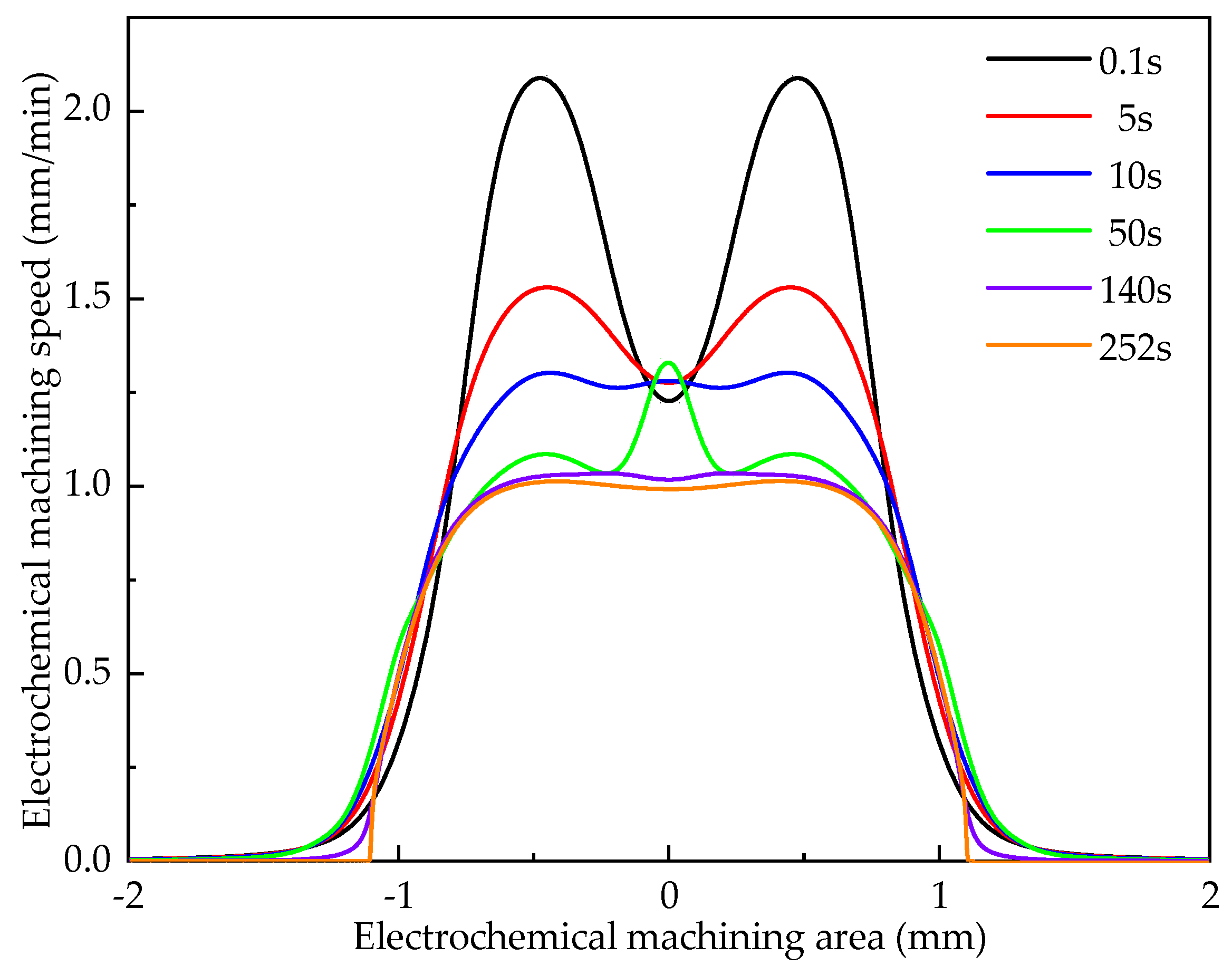
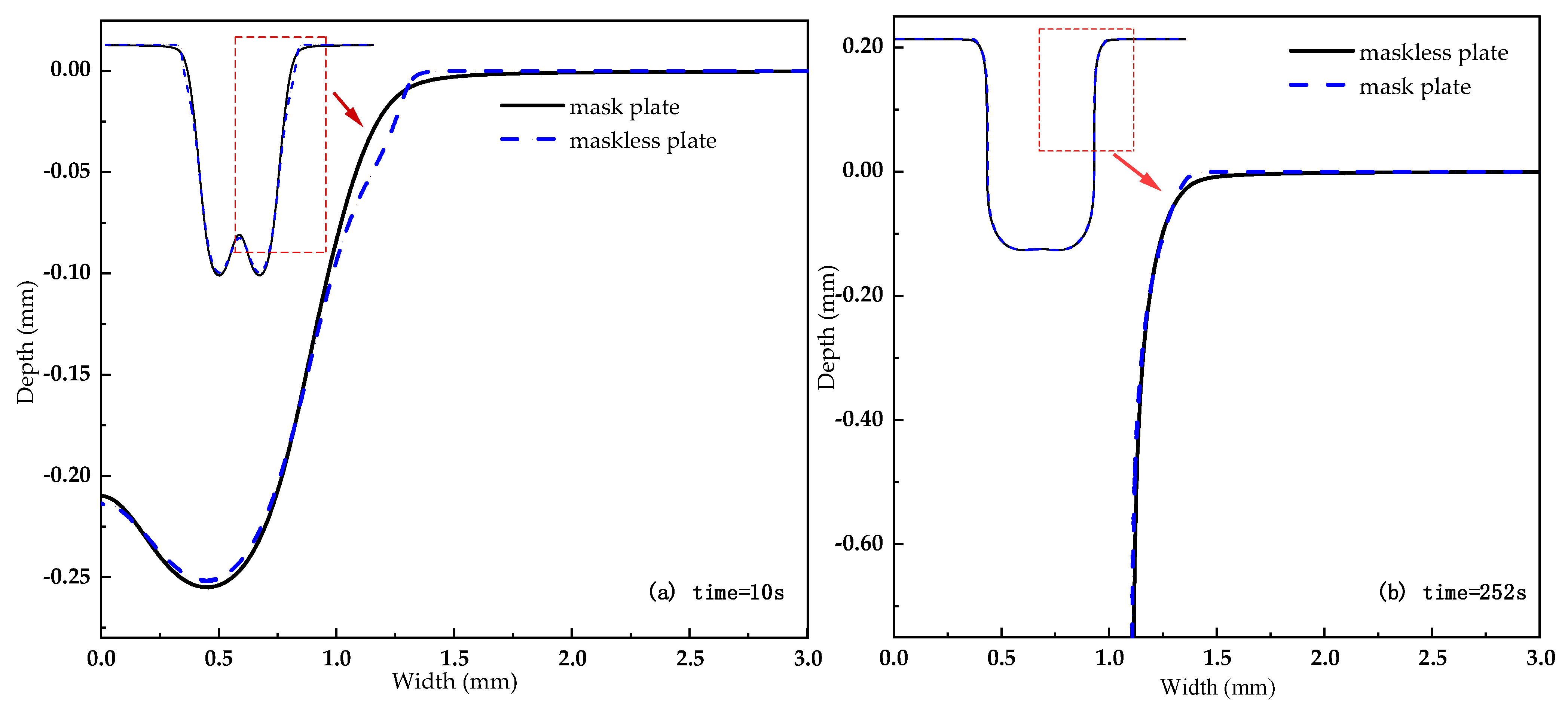
3.1. Analysis of Dynamic Forming Process of Cooling Hole

In electrochemical machining, under the action of electric field, the surface morphology of workpiece changes due to electrolytic reaction and the geometric structure of machining gap changes. The formation process of cooling holes is numerically simulated by COMSOL software. The conditions used in the simulation are shown in Table 3, acquire the cooling hole forming rule, as shown in Figure 4. As can be seen from the figure, with the increase of processing time, the variation law of cooling aperture accords with Faraday’s law. The forming process of cooling holes can be roughly divided into three stages: 0.1–5 s is the initial stage of machining, and the dissolution rate in the middle area of the workpiece surface is relatively low, while the dissolution rate of the two sides is relatively high; 10–50 s is the middle stage of machining, and the dissolution rate in the middle area of the workpiece surface gradually increases, while the dissolution rate on both sides gradually decreases. The time of 140–252 s is the stable stage of machining, and the dissolution rate of the workpiece surface is relatively uniform.
Figure 5 shows the numerical simulation diagram of mask and maskless cooling hole formation. It can be seen from Figure 5a that the maskless electrochemical machining has a larger radial overcut at the entrance, a smaller dissolving area on the side wall, and a larger taper of the side wall during processing for 10 s. It can be seen from Figure 5b that as the processing depth increases, the sidewall dissolution range of the two processing methods is basically the same. Therefore, the mask has a greater impact on the accuracy of the ECM entrance, and the impact on the diameter and taper gradually becomes smaller as the processing depth increases.
Figure 6 shows the formation process of the cooling hole of the mask electrochemical machining. It can be seen from the figure that the inlet processing stage is 10–30 s, and the diameter change of the cooling hole inlet processing section tends to be stable with the increase of the electrode feed depth. When the processing time is 30–300 s, the diameter change of the ECM cooling hole is gradually stable, and the overall appearance is that the entrance diameter is larger, and the diameter change is smaller during the stable processing stage.
Table 4 shows the data comparison of the forming accuracy of mask electrochemical machining. It can be seen from the table that mask electrochemical machining plays an important role in increasing the entrance radius of the cooling hole. The entrance radius of the mask electrical machining is reduced by about 16.0%, and the end radius and the average radius are increased by about 2.4% and 1.3%, respectively. However, the taper is 52.8% lower, which greatly reduces the taper error of the cooling hole in electrochemical machining.
According to the basic principle of electrochemical machining, under the action of voltage, the electrolyte is sprayed on the workpiece from the inside of the tubular electrode, forming an electric field. Since the mask is insulated, the range of action of the electric field between the electrode and the workpiece is effectively limited [33,34,35]. Therefore, the size and shape of the inlet section can be improved, and the taper of the inlet section due to electrochemical corrosion can be reduced. However, when the machining enters a stable stage, the electric field between the electrode and the workpiece is stable, and the electrolytic reaction speed is balanced with the electrode feeding speed. Therefore, the shapes of the mask stabilizing section are basically the same as that of the unmasked cooling hole machining, and the simulation accords with electrochemical machining.

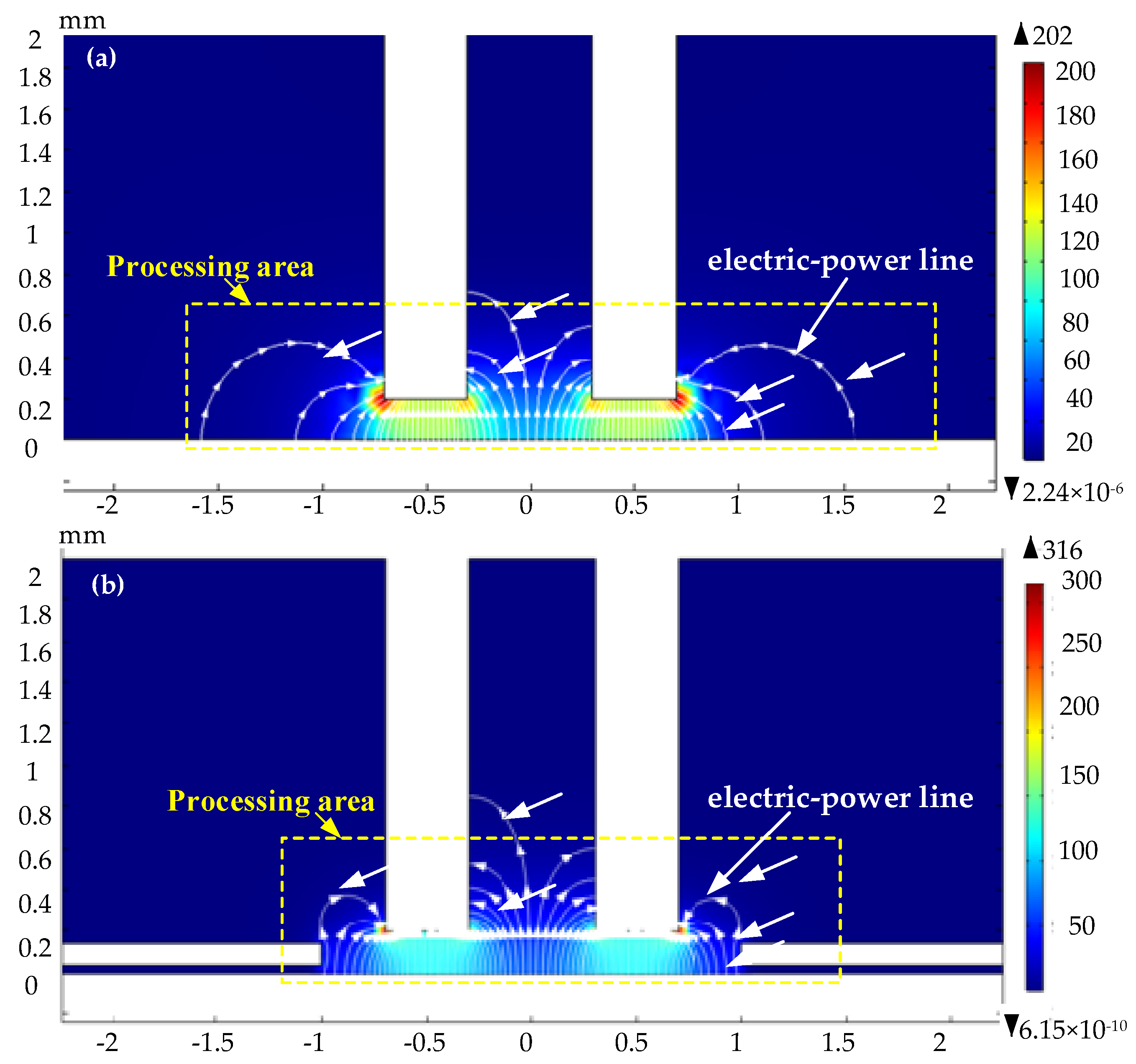
3.2. Simulation Analysis of Electric Field Distribution

The conditions used in the simulation are shown in Table 3. The mask diameter is 2 mm, and the mask thickness is 0.1 mm. Figure 7 shows the distribution of electric field lines in the machining area at the initial stage of the cooling hole in electrochemical machining. The white lines in the figure are electric field lines. The arrow direction is the direction of current flow. The more concentrated the electric field line, the greater the current density. As shown in Figure 7, the electric field lines are mainly distributed in the machining area composed of electrode end face and workpiece surface. The number of field lines decreases gradually along both sides. Figure 7a the number of electric field lines is 60 and the distribution range is large. Figure 7b the number of electric field lines is 84 and evenly distributed within the mask range. These results indicate that the mask ECM can improve the electric field distribution and the entrance precision of machining.
The distribution of the surface current density of the workpiece in the entry stage with time is shown in Figure 8. It can be seen from the figure that the current value at the electrode end of the workpiece surface is larger and the distribution range is larger, and it gradually approaches zero along the two sides of the electrode. The surface current density of the mask electrochemical machining workpiece is relatively large. For example, when the machining time is 0.1 s, 10 s, and 17 s, the maximum current density of the mask electrochemical machining at the entrance stage is 118.081 A/cm2, 77.917 A/cm2 and 69.309 A/cm2, the maximum current density of maskless electrochemical machining is 107.307 A/cm2, 74.452 A/cm2 and 64.933 A/cm2, respectively. This shows that the mask electrochemical machining efficiency is higher, the effective current density range (current density >10 A/cm2) is more concentrated, and the entrance accuracy is better.
According to Faraday’s law, the greater the number of power lines per unit area, the greater the current density [36,37]. Since the voltage between the electrode and the workpiece is constant, the mask can effectively increase the number of power lines per unit area and the current density between the electrode and the workpiece, so the current density of electrochemical machining with mask is higher than that without mask.

3.3. Process Parameter Analysis

In order to better analyze the influence rule of process parameters in the process of ECM, the simulation conditions are as follows: the processing voltage is 24 V, the electrolyte is 16% NaNO3 solution, and the inlet flow rate is 8 m/s. The electric field distribution law in the process of cooling hole electrochemical machining is simulated, which provides guidance for analyzing the influence of different technological parameters on the forming law of cooling hole electrochemical machining.
As can be seen from Figure 9, the minimum conductivity in the machining gap occurs in a narrow area in the end gap, and the maximum conductivity occurs in the corner of the electrode. The electrical conductivity in the gap first decreases and then increases, while the temperature at the side channel and electrolyte outlet gradually increases. The maximum electrical conductivity in the machining gap is 17.6, and the range of electrical conductivity is about 8.1. Main reasons: the electrical conductivity is affected by temperature and gas. When the temperature rises, the electrical conductivity increases, the gas volume fraction increases and the electrical conductivity decreases. At the narrow area in the end face, the temperature and gas volume fraction are particularly small, so the electrical conductivity is the smallest under the combined action of them. The influence of the temperature at the corner of the electrode on the electrical conductivity is far greater than the volume fraction of hydrogen, so the electrical conductivity is the largest.
As can be seen from Figure 10: the conductivity of the front part of electrolyte flow slowly increases with the increase of machining voltage, and the conductivity of the second half decreases rapidly with the increase of machining voltage. When the processing voltages are 12 V, 16 V, 20 V and 24 V, the range of surface conductivity of the workpiece is 0.63 S/m, 0.95 S/m, 1.44 S/m and 1.81 S/m, respectively. The main reason is that the change of electrical conductivity is the result of the interaction of temperature and hydrogen. With the increase of voltage, more and more heat and hydrogen are accumulated in the machining gap, and the increase or decrease of the surface conductivity of theworkpiece is faster and faster with the increase of machining voltage. It can be seen from Table 5 that the average current density of the workpiece surface increases with the increase of voltage, which is beneficial to improving the efficiency of cooling holes in electrochemical machining. However, with the increase of machining voltage, the range and variance of current density on the workpiece surface gradually increase, which leads to “bulge” on the workpiece surface during machining and increases the profile error.
Different inlet flow rates of electrolyte (6 m/s, 9 m/s, 12 m/s, 15 m/s) were used to simulate and analyze cooling holes in electrochemical machining. Select fixed processing parameters, that is, the processing voltage was 20 V, and the electrolyte was 12% NaNO3 solution. The temperature, hydrogen volume fraction and conductivity distribution of the workpiece surface under different electrolyte inlet flow rates are analyzed, and the current density distribution of the workpiece surface to the tool electrode under multi-physical field coupling conditions is studied.
As can be seen from Figure 11: when the inlet flow rate is low, the conductivity of the front part of electrolyte flow increases relatively quickly, and with the increase of inlet flow rate, the conductivity of the second half of the electrolyte flow gradually increases, but generally keeps the law of decreasing first and then increasing. When the inlet flow rate increases within a certain range, the electrical conductivity changes little. When the maximum inlet velocities are 6 m/s, 9 m/s, 12 m/s and 15 m/s, the surface conductivity ranges of the workpiece are 1.831, 1.535, 1.413 and 1.319, respectively. Main reasons: Low-speed electrolyte can not take away heat and hydrogen in the machining gap in time, which leads to the continuous rise of the overall temperature of the workpiece surface and the rapid accumulation of hydrogen. The increase of flow velocity will aggravate the eddy current effect and increase the difficulty of removing heat and hydrogen. The electrical conductivity in the front part increases slowly mainly due to the influence of temperature, while the electrical conductivity of the second half decreases rapidly mainly due to the increase of hydrogen volume fraction, while the electrical conductivity increases continuously with the decrease of hydrogen content and the continuous increase of temperature.
It can be seen from Table 6 that with the increase of electrolyte flow rate, the average range and variance of current density on the workpiece surface gradually decrease, but the overall change range is small. Increasing electrolyte flow rate is beneficial to improve the uniformity of current density on the machined surface of the cooling hole.
According to the mathematical model of electrochemical machining established in Section 2.1, it can be seen that when the voltage between the electrode and the workpiece increases, the current density increases, the electrolyte flow at the inlet of the electrode increases, the removal rate of electrolysis products, electrolysis heat and bubbles between the electrode and the workpiece in unit time increases, the electrolyte renewal rate increases and the current density increases [38,39]. Therefore, the analysis in this section is correct and is consistent with the mathematical model established in Section 2.1.

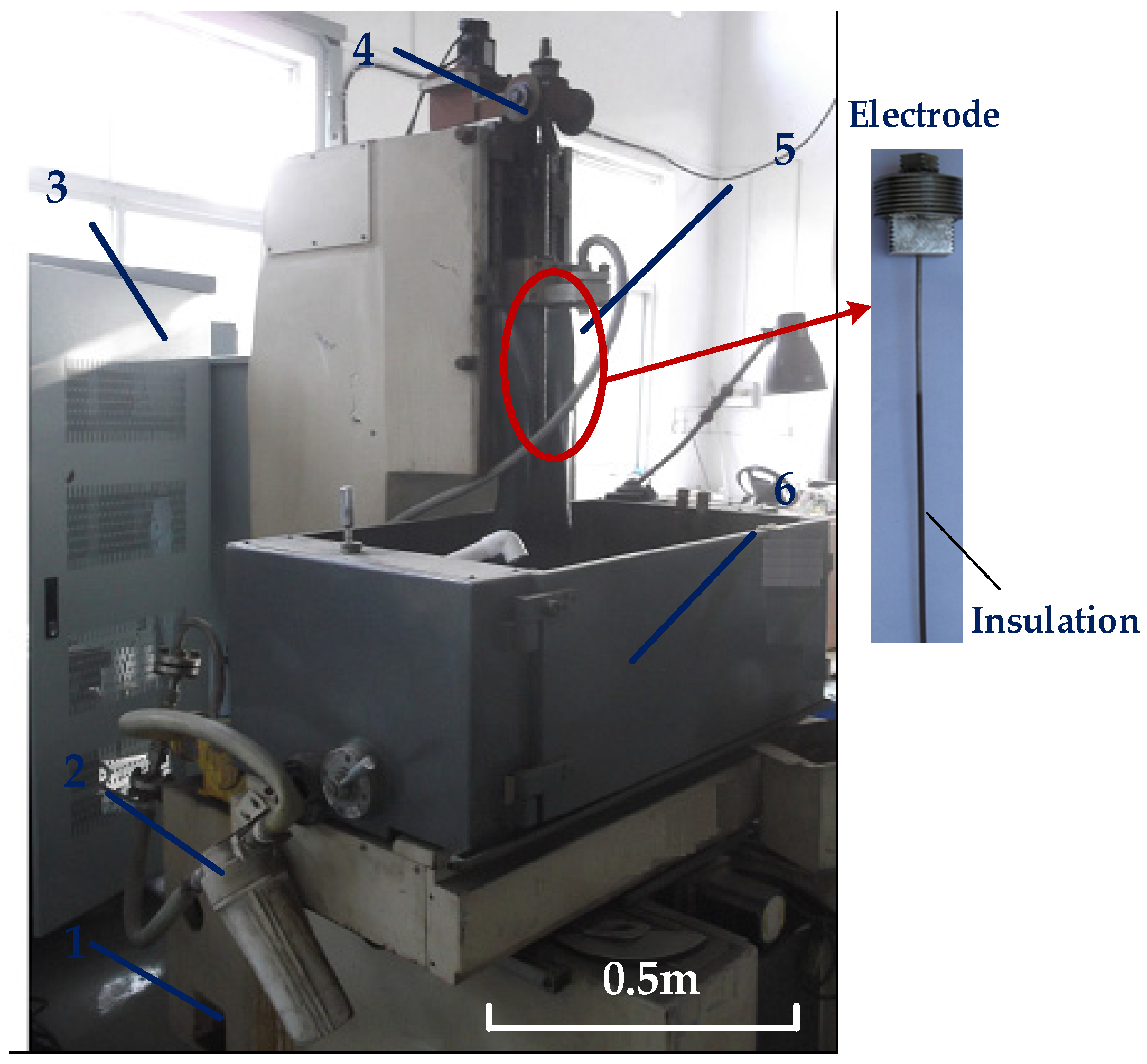
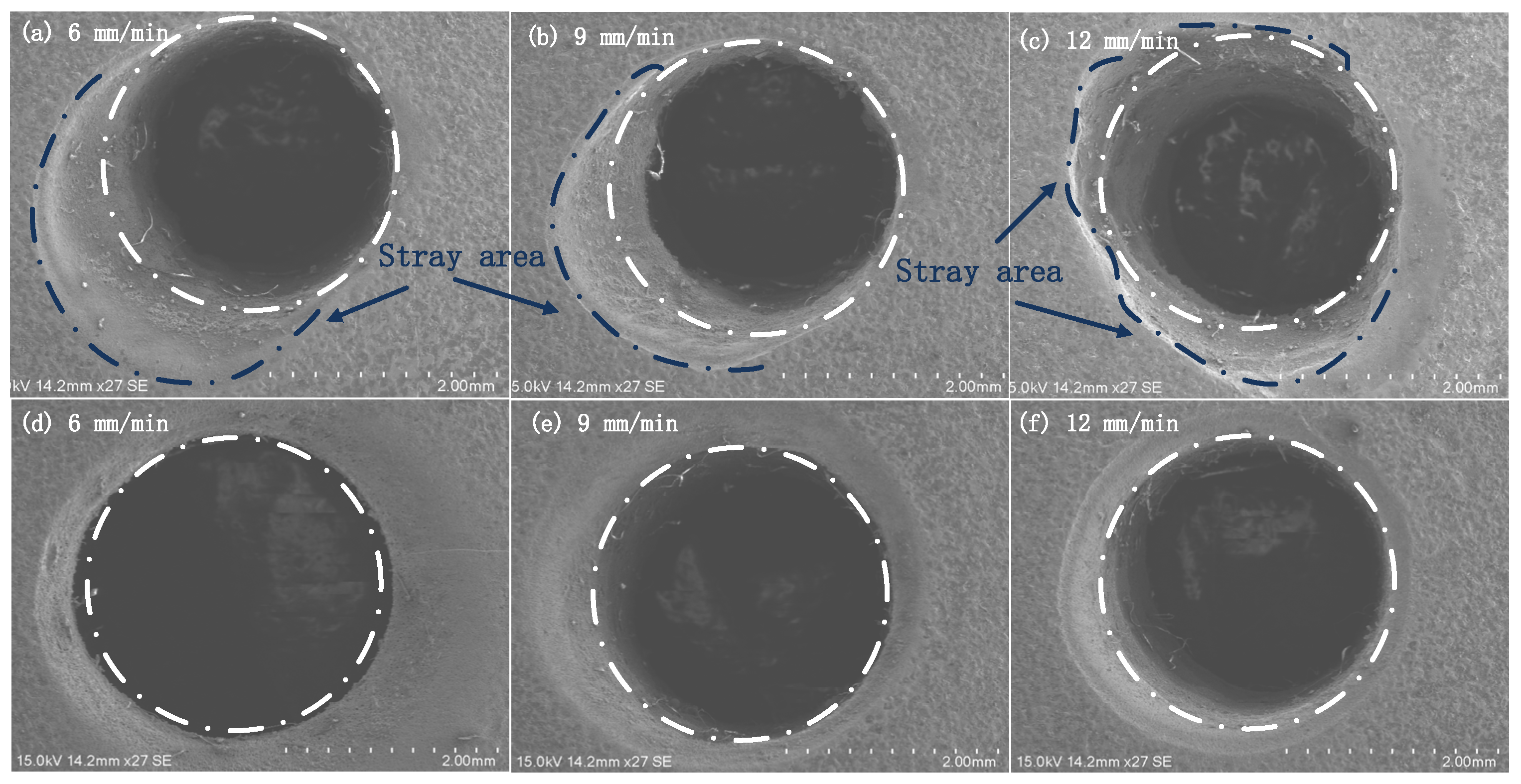
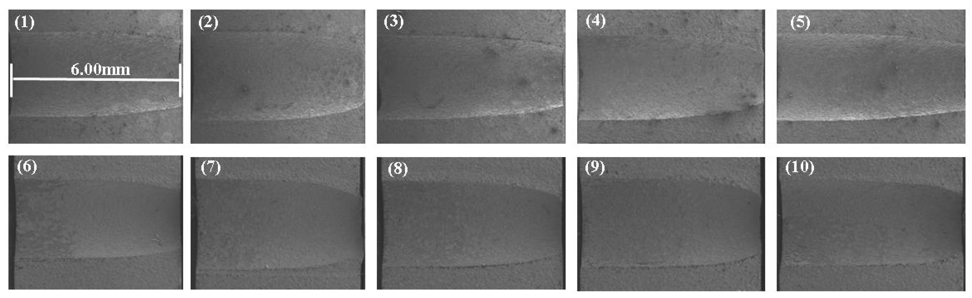
4. Experimental Verification of Electrochemical Machining

In this part, the simulation model analysis is verified by experiments, and the electrochemical machining process parameters and workpieces are the same as the simulation settings. The specific experimental conditions are shown in Table 7. The workpiece is GH 4169, the electrode is a tubular titanium (high current density efficiency and high corrosion resistance) alloy electrode with an inner diameter of 0.6 mm and an outer diameter of 1.4 mm (covered with PTFE insulating film), and the electrolyte is sodium nitrate aqueous solution (according to the workpiece material GH 4169, strong acid electrolyte is selected, which has high current density efficiency).
Combined with the parameter values of mask diameter and mask thickness in Table 3 and the parameter values of voltage, electrolyte concentration and electrolyte flow rate in Table 7, an orthogonal test was carried out, and the hole was cut open by wire cutting. According to the Formulas (6) and (7), measure the inlet diameter and calculate the taper of cooling holes, analyze the change of inlet diameter and taper in mask electrochemical machining and maskless electrochemical machining, and analyze the influence rules of different mask diameters and mask thicknesses on the inlet diameter and taper of cooling holes. The entrance morphology and side taper of small holes are measured by SEM, as shown in Figure 12 and Figure 13.
The analysis shows that in maskless electrochemical machining, the range of electric field lines between electrode and workpiece is larger than that in maskless electrochemical machining, which leads to stray corrosion [40,41,42]. As shown in Figure 12a–c, the stray area is irregular, which is related to the uniformity of the composition distribution of GH 4169 alloy. However, in maskless ECM, the stray corrosion at the inlet end is obviously reduced, and the appearance accuracy of the inlet section is high, as shown in Figure 12d–f. The experimental results are consistent with those of the three-part simulation analysis, which proves the authenticity and reliability of the three-part simulation analysis.
The Figure 13 shows the cross-sectional view of the actual machining hole (1–5 mark electrochemical machining and 6–10 mark less electrochemical machining).
As can be seen from Figure 13, when using maskless ECM (1–5), the diameter of the inlet end of ECM is larger than that of the middle section, and the taper of the whole cross section is larger; when using mask ECM (6–10), the diameter of the inlet end of ECM is smaller than that of the middle section, and the taper of the whole cross section is smaller. This is because the mask structure effectively concentrates the electric field area at the entrance end, which is consistent with the simulation results in Section 3.2.
Figure 14 shows the influence of the diameter of the mask on the entrance radius of the cooling hole when the height of the mask is 0.1 mm. It can be seen from the figure that as the diameter of the mask increases from 2 mm to 2.8 mm, the entrance radius of the cooling hole increases from 1.257 mm to 1.451 mm, indicating that the improvement effect of the mask structure on the entrance size of the cooling hole increases with the increase of the mask diameter and gradually decreases. For example, when the diameter of the mask continues to increase to 3 mm, the cooling hole entrance radius is 1.521, and the influence of the mask structure disappears.
Figure 15 shows the influence of the mask diameter on the taper of the cooling hole. It can be seen from the figure that as the diameter of the mask increases from 2.0 mm to 3 mm, the taper reaches its minimum value before the diameter of 2.2 mm, and then gradually increases. Therefore, reducing the diameter of the mask does not always reduce the taper of the cooling hole. When the mask diameter is 2.2 mm, the taper of the cooling hole is reduced by 53.4% compared with electrochemical machining, and the improvement effect is the best.
Figure 16 shows the influence of the mask thickness on the initial radius of the cooling hole when the mask diameter is 2.2 mm. It can be seen from the figure that when the mask thickness is increased from 0.08 mm to 0.13 mm, the overall cooling hole radius changes little, floating in the range of 1.318 mm to 1.334 mm, but the overall size is lower than the ECM entrance size. It can be seen that the change of the mask thickness has little effect on the distribution of the entrance radius of the cooling hole.
Figure 17 shows the effect of mask thickness on the entrance radius of the cooling hole. It can be seen from the figure that when the mask thickness is increased from 0.08 mm to 0.13 mm, the taper of the cooling hole fluctuates in the range of 2.858° to 2.947°, and the overall floating range is small, but the overall taper is lower than the ECM entrance. The change of the mask thickness has little effect on the distribution of the taper of the cooling holes.
Through the comparative analysis of the above experiments, it can be seen that the appearance of the entrance of the mask ECM is good, which is consistent with theoretical model analysis and simulation analysis [43,44]. The structural insulation of the mask can improve the current density between the electrode and the workpiece and reduce stray corrosion, thus verifying the accuracy of the second part of mathematical modeling and the third part of simulation analysis. At the same time, the influence of the thickness and diameter of the mask on the entrance diameter and taper of the cooling hole ECM is analyzed.

5. Conclusions

In this paper, through studying the principle of electrochemical corrosion, combining with classical electrochemical theory, the simulation model of mask electrochemical machining is established, and the distribution of electric field in the process of mask and unmasked electrochemical machining is analyzed. Through simulation experiments, the influence of different mask diameters and heights on the size and morphology of cooling holes in electrochemical machining is studied, and the mask electrochemical machining process has no damage and can be reused, which improves the machining efficiency [45,46]. Based on the current density of workpiece surface obtained by multi-physical field coupling simulation model, with the help of any Lagrange-Eulerian formula, the mathematical model of anode boundary movement with respect to current density is established, and the formation law of the size and shape of cooling holes in electrochemical machining under different machining voltages and electrolyte inlet flow rates is analyzed. The conclusions are as follows.
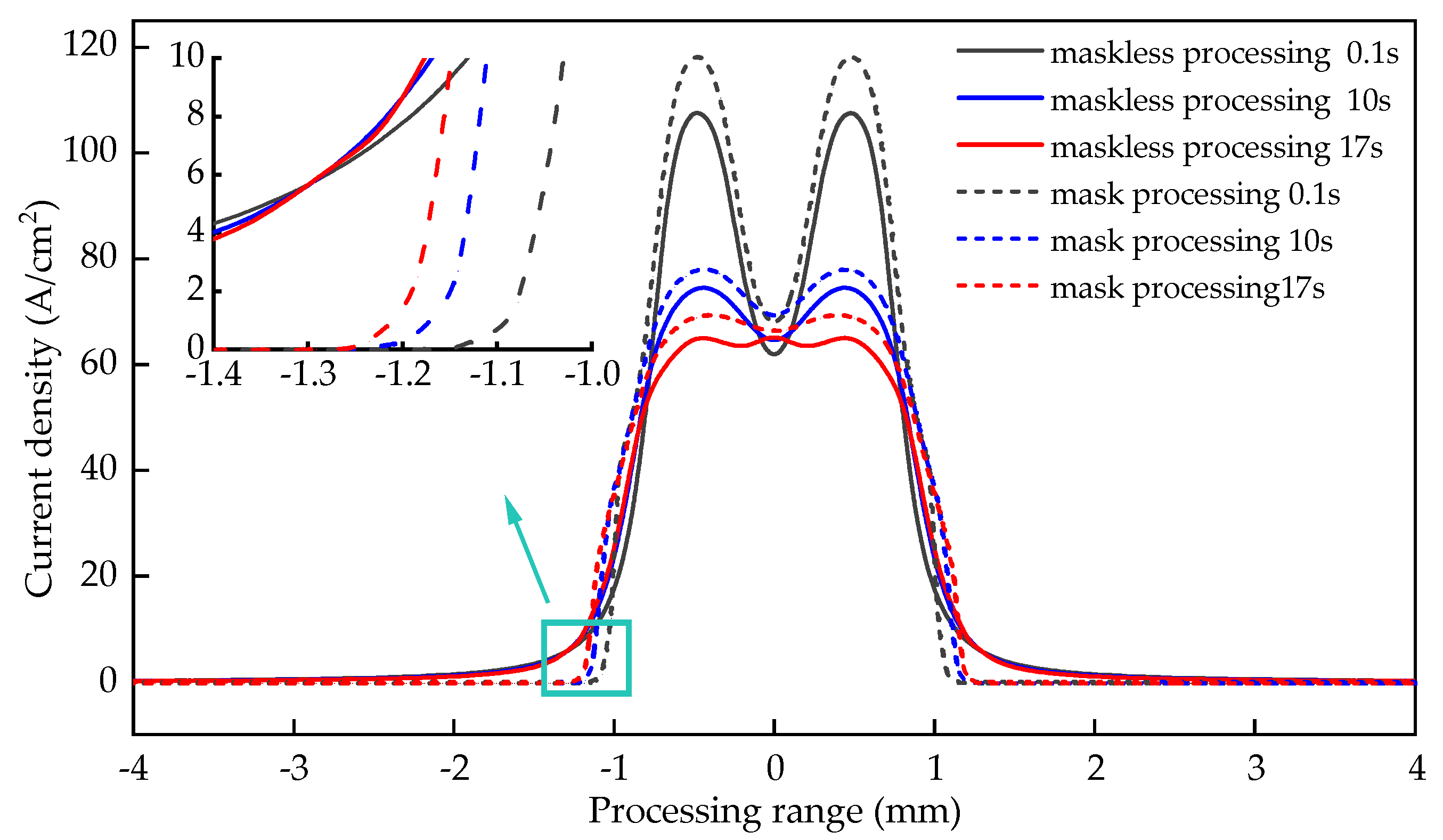
  • Establish the simulation model of cooling hole in mask electrochemical machining. The electric field distribution in the initial stage of masked and unmasked electrochemical machining was compared. The dynamic forming process of cooling hole in electrochemical machining is obtained. the deviation between experimental and simulated inlet diameter is 5.6%, the deviation between experimental and simulated outlet diameter is 5.9%, the deviation between experimental and simulated average diameter is 2.9%, the deviation between experimental and simulated taper is 4.3%.
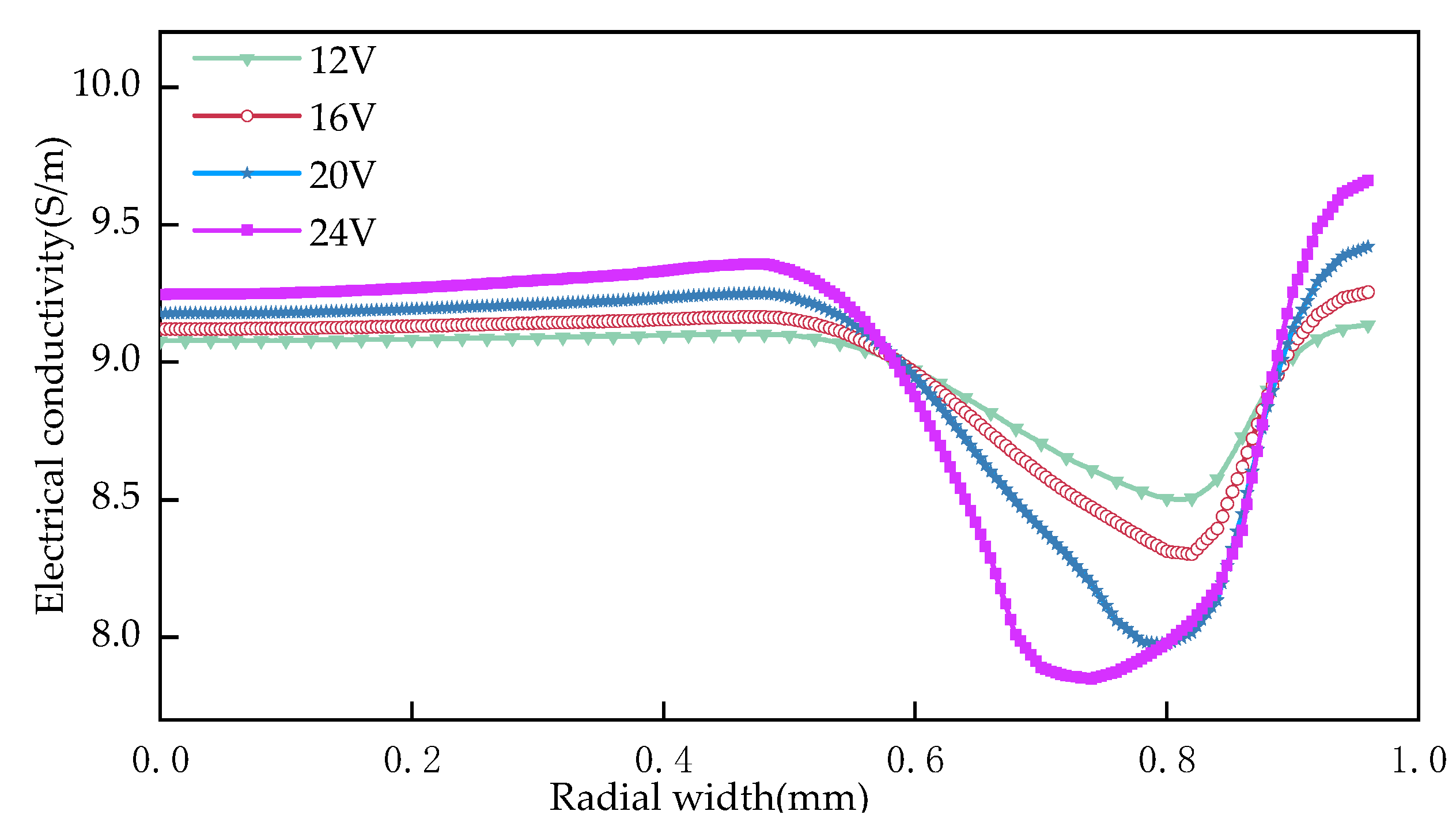
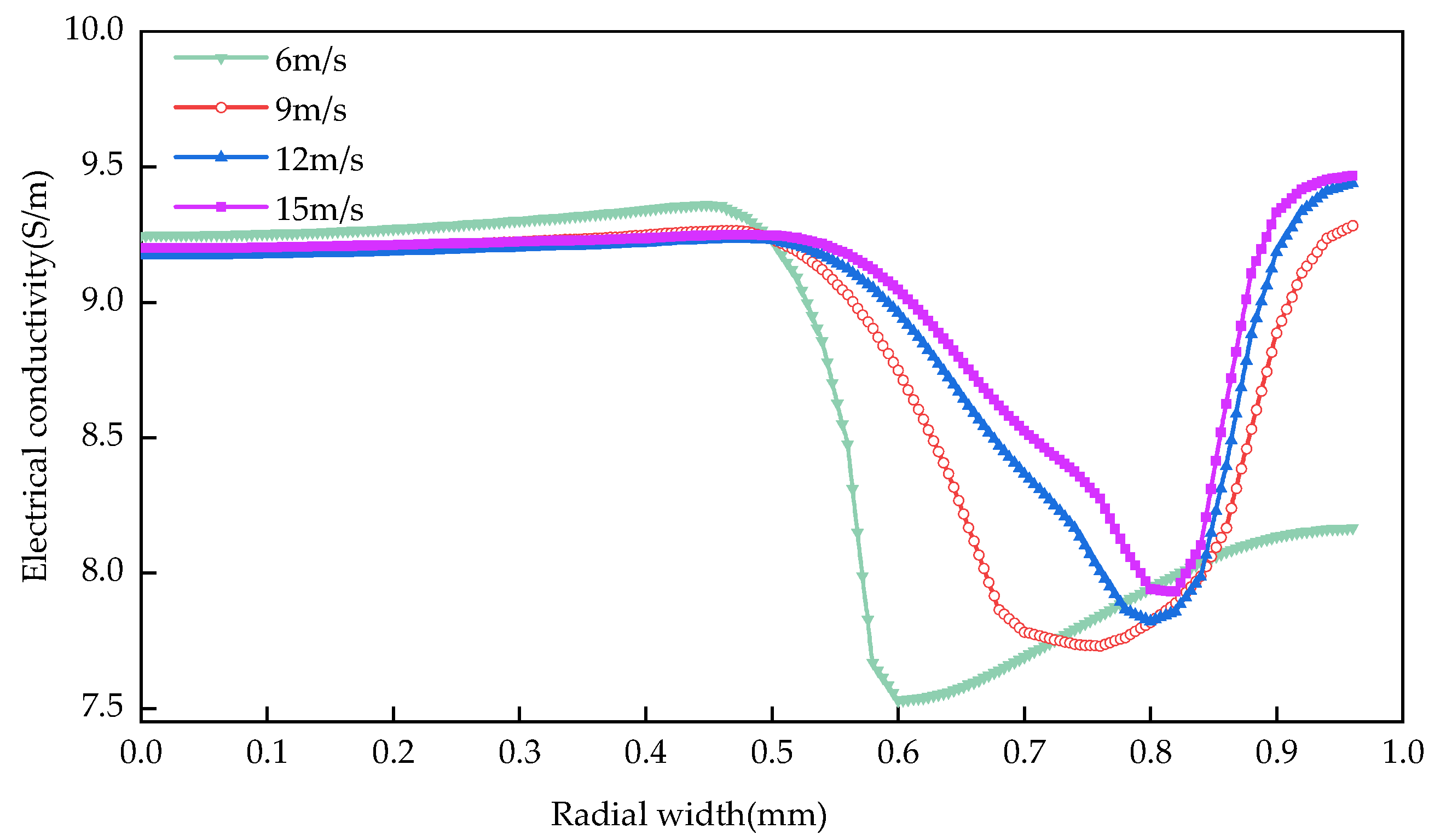
  • The simulation model of cooling holes in electrochemical machining is established, and the distribution of electrical conductivity in machining gap is adjusted. The relationship between this rule and processing voltage and inlet flow is analyzed by simulation. Simulation result show that the uniformity of electric field distribution is poor with the increase of processing voltage; The current density distribution on the surface of cooling holes under different process parameters is also studied. With the increase of processing voltage from 12 V to 24 V, the surface conductivity of the workpiece increases from 0.63 s/m to 1.81 s/m. When the inlet speed increases from 6 m/s to 15 m/s, the surface conductivity of the workpiece decreases from 1.83 s/m to 1.32 s/m. The results show that the machining voltage is an important factor that affects the machining accuracy of cooling holes, and the influence of the change of inlet speed is relatively small.
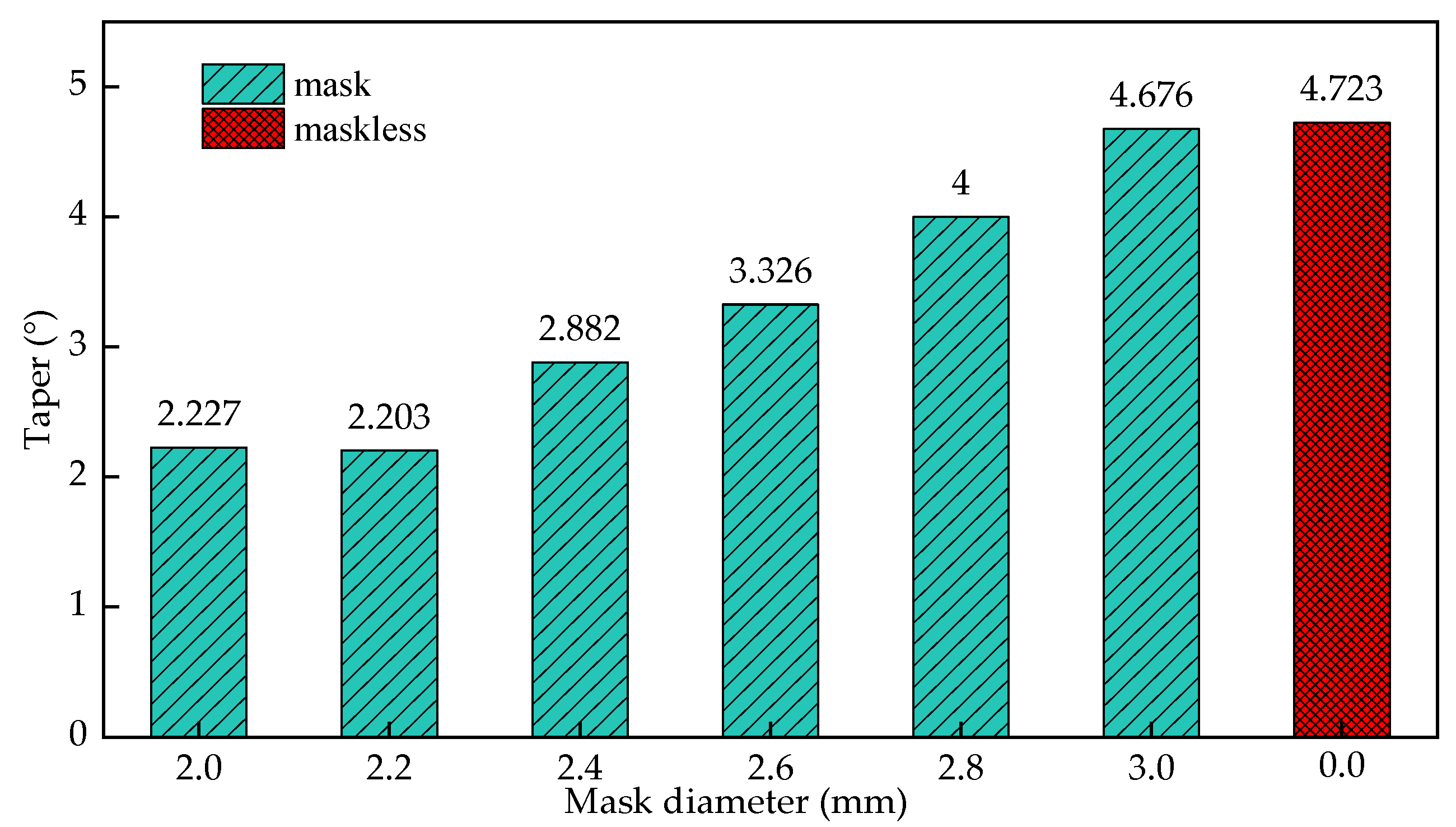
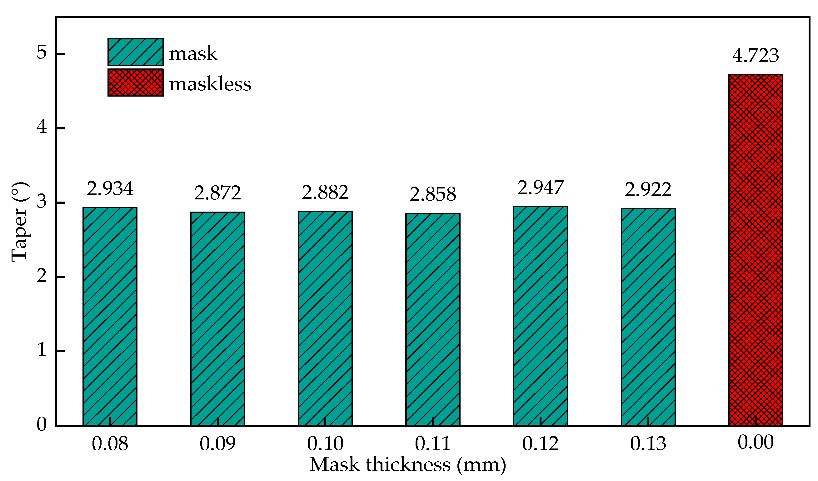
  • Under different mask conditions, the size characteristics of cooling holes were analyzed. The results show that the inlet radius of cooling hole decreases with the decrease of mask diameter. The change of mask thickness has little effect on the forming precision of cooling hole. The diameter of the mask increases from 2 mm to 2.8 mm, the entrance radius of the cooling hole increases from 1.257 mm to 1.451 mm, when the diameter of the mask continues to increase to 3 mm, the cooling hole entrance radius is 1.521, and the influence of the mask structure disappears. The diameter of the mask increases from 2.0 mm to 3 mm, the taper reaches its minimum value before the diameter of 2.2 mm, and then gradually increases.
To sum up, mask electrochemical machining can effectively improve the machining accuracy of GH 4169 cooling hole and provide a new machining method for improving the service performance and service life of aero-engine.

Author Contributions

Conceptualization, Z.L., Y.D.; methodology, Z.L., Y.D.; validation, Z.L., Y.D.; formal analysis, Z.L., Y.D.; investigation, Z.L., Y.D.; resources, Z.L., Y.D.; data curation, Z.L.; writing—original draft preparation, Z.L.; writing—review and editing, Z.L.; visualization, Z.L.; supervision, Z.L.; project administration, Z.L. and Y.D.; funding acquisition, Z.L. and Y.D. All authors have read and agreed to the published version of the manuscript.

Funding

The study is supported by the Natural Science Foundation of China (Grant No. 52075134); Natural Science Foundation of Heilongjiang Province of China (Grant No. LH2019E062); Postdoctoral Scientific Research Developmental Fund of Heilongjiang Province of China (Grant No. LBH-Q20097); Fundamental Research Foundation for Universities of Heilongjiang Province, China (LGYC2018JC040).

Institutional Review Board Statement

Not applicable.

Informed Consent Statement

Not applicable.

Data Availability Statement

Data is contained within the article.

Acknowledgments

The authors would like to thank Key Laboratory of Advanced Manufacturing Intelligent Technology of Ministry of Education for helpful discussions on topics related to this work. The authors are grateful to Bingren Cao for his help with the preparation of figures in this paper.

Conflicts of Interest

The authors declare no conflict of interest.

Abbreviations

ECMElectrochemical machining
Kmass electrochemical equivalent
ωvolume electrochemical equivalent
A1, A2,…Aithe relative atomic mass
n1, n2,…nithe valence
a1, a2,…aipercentage of metal element content
φthe potential
Ethe electric field intensity
σthe conductivity of electrolyte
Rinthe inlet radius
Routtheoutlet radius
Raverthemean radius
θthetaper of electrolytic machining of cooling holes
nthe sampling times along the radius of the cooling hole depth
Rithe measured radius along the radius of the cooling hole depth

References

  1. Wang, Z.; Lv, Y.M. Cutting Force Simulation of Superalloy GH4169 Based on ABAQUS. Light Ind. Mach. 2019, 37, 42–45. [Google Scholar]
  2. Dai, H.W.; Zhang, J.H.; Ren, Y.Y.; Liu, N.H.; Lin, J.W. Effect of cooling hole configurations on combustion and heat transfer in an aero-engine combustor. Appl. Therm. Eng. 2021, 182, 115664. [Google Scholar] [CrossRef]
  3. Li, C.J.; Li, Y.; Tong, H.; Zhao, L.; Kong, Q.C.; Wang, Z.Q. An EDM pulse power generator and its feasible experiments for drilling film cooling holes. Int. J. Adv. Manuf. Technol. 2016, 87, 1813–1821. [Google Scholar] [CrossRef]
  4. Zheng, H.; Lam, Y.; Sundarraman, C.; Tran, D.V. Influence of substrate cooling on femtosecond laser machined hole depth and diameter. Appl. Phys. A 2007, 89, 559–563. [Google Scholar] [CrossRef]
  5. Liu, H.; Zhao, W.; Wang, L.; Shen, X.; Wang, N.; Wang, X. Percussion Drilling of Deep Holes Using Picosecond Ultrashort Pulse Laser in Ni-Based Superalloy Coated with Ceramic Thermal Barrier Coatings. Materials 2020, 13, 3570. [Google Scholar] [CrossRef]
  6. Xu, J.; Ji, M.; Chen, M.; El Mansori, M. Experimental investigation on drilling machinability and hole quality of CFRP/Ti6Al4V stacks under different cooling conditions. Int. J. Adv. Manuf. Technol. 2020, 109, 1527–1539. [Google Scholar] [CrossRef]
  7. Iqbal, A.; Zhao, G.; Zaini, J.; Gupta, M.K.; Jamil, M.; He, N.; Nauman, M.M.; Mikolajczyk, T.; Pimenov, D.Y. Between-the-Holes Cryogenic Cooling of the Tool in Hole-Making of Ti-6Al-4V and CFRP. Materials 2021, 14, 795. [Google Scholar] [CrossRef]
  8. Wang, F.; Wang, Y. Research on milling hole of AFRP based on cryogenic cooling processing. Int. J. Adv. Manuf. Technol. 2020, 106, 5277–5287. [Google Scholar] [CrossRef]
  9. Zhang, W.; Zhou, S.; Wu, Z.H.; Li, G.C.; Kou, Z.H. Film Cooling Mechanism of Combined Hole and Saw-tooth Slot. Int. J. Turbo Jet-Engines 2019, 36, 425–433. [Google Scholar] [CrossRef]
  10. Ye, Z.; Wang, Y.G.; Yu, X. Study on the reaming process of aluminum alloy 7050-T7451 under different cooling conditions. Adv. Manuf. 2021. [Google Scholar] [CrossRef]
  11. Kumar, M.S.; Reddy, S.R.; Vasu, V. A 3-D simulation and experimental study of cutting forces in turning Inconel-718. Mater. Today Proc. 2017, 4, 9942–9945. [Google Scholar]
  12. Pawade, R.S.; Joshi, S.S.; Brahmankar, P.K.; Rahman, M. An investigation of cutting forces and surface damage in high speed turning of Inconel 718. J. Mater. Process. Technol. 2007, 192, 139–146. [Google Scholar] [CrossRef]
  13. Han, J.C. Recent developments in turbine blade internal cooling. N. Y. Acad. Sci. 2001, 934, 162–178. [Google Scholar] [CrossRef] [PubMed]
  14. Rajurkar, K.P.; Zhu, D.; McGeough, J.A.; Kozak, J.; DeSilva, A. New Developments in Electro-Chemical Machining. IRP Ann. 1999, 48, 567–579. [Google Scholar] [CrossRef]
  15. Wang, F.; Xiao, J.; Yue, L.; Wu, X.Y.; Zhao, J.S. Common Key Technology of Precise Electrochemical Machining and Its Application in Aviation Manufacturing. Electromach. Mould 2020, 1, 1–6. [Google Scholar]
  16. Zhang, C.X.; Xu, Z.Y.; Hang, Y.S.; Xing, J. Effect of solution conductivity on tool electrode wear in electrochemical discharge drilling of nickel-based alloy. Int. J. Adv. Manuf. Technol. 2019, 103, 743–756. [Google Scholar] [CrossRef]
  17. Wang, G.Q.; Zhang, Y.; Li, H.S.; Tang, J. Ultrasound-assisted through-mask electrochemical machining of hole arrays in ODS super alloy. Materials 2020, 13, 5780. [Google Scholar] [CrossRef] [PubMed]
  18. Niu, S.; Qu, N.S.; Yue, X.K.; Li, H.S. Effect of tool-sidewall outlet hole design on machining performance in electrochemical mill-grinding of Inconel 718. J. Manuf. Process. 2019, 41, 10–22. [Google Scholar] [CrossRef]
  19. Zou, H.; Yue, X.M.; Luo, H.X.; Liu, B.H.; Zhang, S.Y. Electrochemical micromachining of micro hole using micro drill with non-conductive mask on the machined surface. J. Manuf. Process. 2020, 59, 366–377. [Google Scholar] [CrossRef]
  20. Li, Z.L.; Cao, B.; Dai, Y. Research on Multi-Physics Coupling Simulation for the Pulse Electrochemical Machining of Holes with Tube Electrodes. Micromachining 2021, 12, 950. [Google Scholar] [CrossRef]
  21. Li, Z.L.; Di, Y. Analysis of multi-physics coupling of small holes in gh4169 alloy by electrolytic processing of tube electrodes. Micromachining 2021, 12, 828. [Google Scholar] [CrossRef] [PubMed]
  22. Hackert-Oschätzchen, M.; Meichsner, G.; Zinecker, M. Micro Machining with Continuous Electrolytic Free Jet. Precis. Eng. 2012, 36, 612–619. [Google Scholar] [CrossRef]
  23. Wang, G.Q.; Li, H.S.; Zhang, C. Improvement of Machining Consistency during Through-mask Electrochemical Large-area Machining. Chin. J. Aeronaut. 2019, 32, 1051–1058. [Google Scholar] [CrossRef]
  24. Abhinav, K.; Arvind, S.; Yadav, H. 3D Simulation of Machining Parameters of Electrochemical Micromachining for Stainless Steel (316L). Mater. Today Proc. 2021, 45, 4565–4570. [Google Scholar]
  25. Ahna, S.H.; Ryua, S.H.; Choib, D.K. Electro-chemical Micro Drilling Using Ultra Short Pulses. Recent Pat. Eng. 2018, 12, 129–134. [Google Scholar] [CrossRef]
  26. Wang, X.D.; Qu, N.S.; Fang, X.L. Electrochemical Drilling with Constant Electrolyte flow. J. Mater. Process. Technol. 2016, 238, 1–7. [Google Scholar] [CrossRef]
  27. Uchiyama, M.; Kunieda, M. Application of Large Deflection Analysis for Tool Design Optimization in an Electrochemical Curved Hole Machining Method. Precis. Eng. 2013, 37, 765–770. [Google Scholar] [CrossRef]
  28. Zhu, D.; Qu, N.S.; Li, H.S. Electrochemical Micromachining of Microstructures of Micro Hole and Dimple Array. CIRP Ann. Manuf. Technol. 2009, 58, 177–180. [Google Scholar] [CrossRef]
  29. Li, H.S.; Gao, C.P.; Wang, G.Q. A Study of Electrochemical Machining of Ti-6Al-4V in NaNO3 solution. Sci. Rep. 2016, 6, 352–358. [Google Scholar] [CrossRef] [Green Version]
  30. Chen, X.L.; Dong, B.Y.; Zhang, C.Y. Jet Electrochemical Machining of Micro Dimples with Conductive Mask. J. Mater. Process. Technol. 2017, 257, 101–111. [Google Scholar] [CrossRef]
  31. Sun, G.R.; Yan, Y.; Dong, J.T.; Zhou, P. Research on Electrochemical Machining Technology of Deep Small Hole Using Suction Electrode. J. Phys. Conf. Ser. 2021, 1948, 012201. [Google Scholar]
  32. Li, Z.; Li, W.; Dai, Y. Experimental Research and Multi-Physical Field Coupling Simulation of Electrochemical Machining Based on Gas–Liquid Two-Phase Flow. Micromachines 2022, 13, 246. [Google Scholar] [CrossRef] [PubMed]
  33. Gu, Z.; Chen, X.; Xu, Z.; Ye, Z.; Li, G. Investigation on Bidirectional Pulse Electrochemical Micromachining of Micro Dimples. Micromachines 2021, 12, 1108. [Google Scholar] [CrossRef] [PubMed]
  34. Wang, J.; Xu, Z.; Wang, J.; Zhu, D. Anodic dissolution characteristics of Inconel 718 in C6H5K3O7 and NaNO3 solutions by pulse electrochemical machining. Corros. Sci. 2021, 183, 109335. [Google Scholar] [CrossRef]
  35. Fan, G.; Chen, X.; Saxena, K.K.; Liu, J.; Guo, Z. Jet Electrochemical Micromachining of Micro-Grooves with Conductive-Masked Porous Cathode. Micromachines 2020, 11, 557. [Google Scholar] [CrossRef]
  36. Gomez-Gallegos, A.; Mill, F.; Mount, A.R.; Duffield, S.; Sherlock, A. 3D multiphysics model for the simulation of electrochemical machining of stainless steel (SS316). Int. J. Adv. Manuf. Technol. 2018, 95, 2959–2972. [Google Scholar] [CrossRef] [Green Version]
  37. Ishida, T.; Takeuchi, Y. L-shaped curved hole creation by means of electrical discharge machining and an electrode curved motion generator. Int. J. Adv. Manuf. Technol. 2002, 19, 260–265. [Google Scholar] [CrossRef]
  38. Zhao, J.S.; Wang, F.; Zhuang, L.; Xiangli, Z.; Weimin, G.; Zongjun, T. Flow Field Design and Process Stability in Electrochemical Machining of Diamond Holes. Chin. J. Aeronaut. 2016, 29, 1830–1839. [Google Scholar]
  39. Li, H.S.; Wang, G.Q.; Qu, N.S.; Zhu, D. Through-mask electrochemical machining of a large-area hole array in a serpentine flow channel. Int. J. Adv. Manuf. Technol. 2017, 89, 933–940. [Google Scholar] [CrossRef]
  40. Dayanand, S.; Bilgi, V.K.; Jaina, R. Electrochemical Deep Hole Drilling in Super Alloy for Turbine Application. J. Mater. Process. Technol. 2003, 149, 445–452. [Google Scholar]
  41. Yang, I.; Park, M.S.; Chu, C.N. Micro ECM with Ultrasonic Vibrations Using aSemi-cylindrical Tool. Int. J. Precis. Eng. Manuf. 2009, 10, 5–10. [Google Scholar] [CrossRef]
  42. Wang, J.; Xu, Z.; Wang, J.; Zhu, D. Electrochemical machining of complex components of aero-engines: Developments, trends, and technological advances. Corros. Sci. 2021, 34, 28–53. [Google Scholar] [CrossRef]
  43. Shu, T.; Liu, Y.; Wang, K.; Peng, T.; Guan, W. Ultrasonic vibration-aided electrochemical drill-grinding of SLM-printed Hastelloy X based on analysis of its electrochemical behavior. Electrochem. Commun. 2022, 135, 107208. [Google Scholar] [CrossRef]
  44. Kozak, J.; Rajurkar, K.P.; Wei, B. Modelling and Analysis of Pulse Electrochemical Machining (PECM). J. Eng. Ind. 1994, 116, 316–323. [Google Scholar] [CrossRef]
  45. Chen, X.L.; Fan, G.C.; Lin, C.H.; Dong, B.Y.; Guo, Z.N.; Fang, X.L.; Qu, N.S. Investigation on the electrochemical machining of micro groove using masked porous cathode. J. Mater. Process. Technol. 2020, 276, 116406. [Google Scholar] [CrossRef]
  46. Liu, B.; Zou, H.; Luo, H.; Yue, X. Investigation on the Electrochemical Micromachining of Micro Through-Hole by Using Micro Helical Electrode. Micromachines 2020, 11, 118. [Google Scholar] [CrossRef] [Green Version]
Figure 1. Diagram of ECM equipment processing small hole (1. Filter 2. pump 3. control system 4. motor 5. electrode 6. working table).
Materials 15 01973 g001
Figure 2. Schematic diagram of electrochemical machining dimensions of cooling holes.
Materials 15 01973 g002
Figure 3. Simulation model of mask electrochemical machining cooling hole.
Materials 15 01973 g003
Figure 4. Numerical simulation diagram of cooling hole forming.
Materials 15 01973 g004
Figure 5. Numerical simulation of the forming of mask and mask-free cooling holes.
Materials 15 01973 g005
Figure 6. Mask electrochemical machining cooling hole forming process ((ac) is the simulation of maskless electrochemical machining process, (a) is 10 s, (b) is 30 s, (c) is 300 s, (df) is the simulation of maskless electrochemical machining process, (d) is 10 s, (e) is 30 s and (f) is 300 s.).
Materials 15 01973 g006
Figure 7. Distribution of electric field lines in the processing area at the initial stage ((a) is the simulation of maskless electrochemical machining process and the distribution of power lines, and (b) is the simulation of mask electrochemical machining process and the distribution of power lines).
Materials 15 01973 g007
Figure 8. The distribution of current density on the workpiece surface with time in the entrance stage.
Materials 15 01973 g008
Figure 9. Conductivity distribution in the machining gap.
Materials 15 01973 g009
Figure 10. Influence of processing voltage on conductivity distribution.
Materials 15 01973 g010
Figure 11. Influence of inlet flow rate on conductivity distribution.
Materials 15 01973 g011
Figure 12. Morphology of cooling hole inlet.
Materials 15 01973 g012
Figure 13. Sectional view of electrochemical machining of cooling holes. (1)Taper 4.40° (2)Taper 4.35° (3)Taper 4.38° (4)Taper 4.41° (5)Taper 4.47° (6)Taper 2.21° (7)Taper 2.64° (8)Taper 2.24° (9)Taper 2.33° (10)Taper 2.52°.
Materials 15 01973 g013
Figure 14. The influence of the mask diameter on the entrance radius of the cooling hole.
Materials 15 01973 g014
Figure 15. The influence of the diameter of the mask on the taper of the cooling hole.
Materials 15 01973 g015
Figure 16. The influence of the mask thickness on the entrance radius of the cooling hole.
Materials 15 01973 g016
Figure 17. The influence of the mask thickness on the entrance radius of the cooling hole.
Materials 15 01973 g017
Table 1. The main elements and content of GH4169.
ElementNiCrNbMoTiAiFe
Atomic mass59529396472756
Percentage50–5517–214.75–5.52.8–3.30.65–1.150.2–0.8Margin
Table 2. Boundary condition setting of cooling hole for mask electrochemical machining.
numerical value5/6/714/15/17/182/6/4/8/9/10/13/19
Current module boundary conditionselectrical potentialelectrical potentialelectrical isolation
setV = UV = 0n×j = 0
numerical value5/6/713/14/15/17/18/19Remaining boundary
Mobile gridboundary conditionsspeedspeedFixed grid
set V n = η ω i V x = 0 , V y = v
Table 3. Basic simulation parameters of mask electrochemical machining.
Basic ParameterNumerical Value
Voltage(V)22
Mask diameter (mm)2/2.2/2.4/2.6/2.8/3
Mask thickness(mm)0.08/0.09/0.1/0.11/0.12/0.13
Electrode feed rate (mm/min)0.7
Feed depth (mm)6.2
Initial clearance (mm)0.2
Electrolyte conductivity (S/m)10.1
Initial temperature (K)293.15
Table 4. Comparison of forming accuracy of mask electrochemical machining.
Entrance Radius
Rin (mm)
Front Radius Rend(mm)Mean Radius Raver (mm)Taper
θ (°)
Mask electrochemical machining1.2571.0241.1062.227
Error (%)3.94.03.04.0
Maskless electrochemical machining1.4961.0001.0924.723
Error (%)5.55.73.54.3
Table 5. Analysis of current density on workpiece surface under different machining voltages.
Voltage/VAverage Value/A/cm2Extreme Difference/A/cm2Variance
1256.6428.7611.21
1676.7440.0515.5
2097.8953.1420.53
24120.6269.8526.66
Table 6. Analysis of current density on the surface of workpieces atdifferent inlet flow rates.
Flow Rate/m/sAverage Value/A/cm2Extreme Difference/A/cm2Variance
6100.558.621.96
997.7953.2520.67
1297.0651.8720.04
1596.7251.1719.8
Table 7. Experimental conditions of electrochemical machining of cooling holes.
Experimental ProjectCondition
ElectrodeTitanium alloy tube electrode
WorkpieceGH4169 nickel base superalloy
Processing voltage12–24 V (DC voltage)
Electrolyte concentrations16% NaNO3 solution
Electrolyte flow rate6–12 mm/min
Publisher’s Note: MDPI stays neutral with regard to jurisdictional claims in published maps and institutional affiliations.

