
Theoretical Model of Bending Moment for Straight Mortise-and-Tenon Joints with Wooden Pegs Involving a Gap

Abstract
:1. Introduction
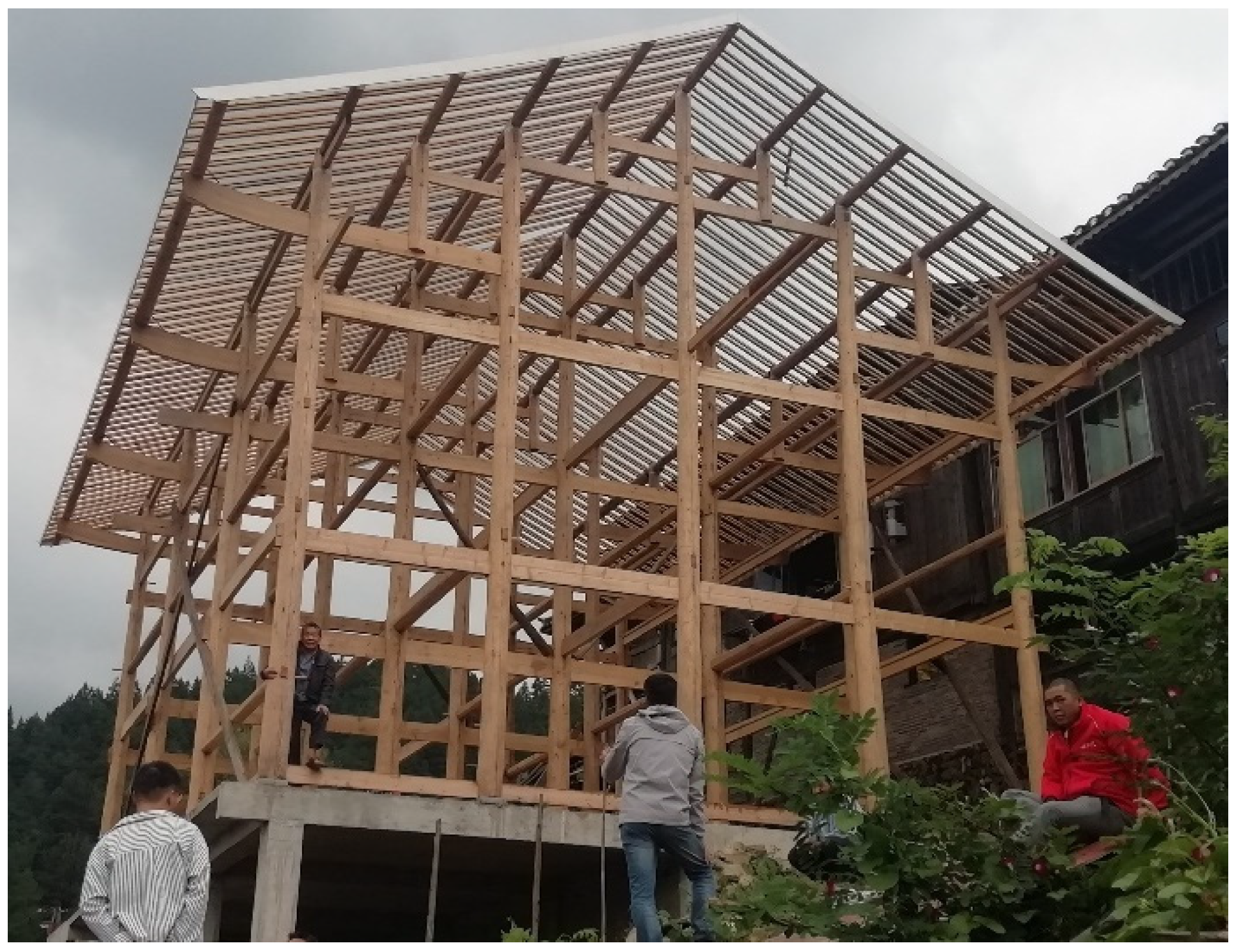
2. Stress Mechanism of SMTJs/WPs in Traditional Wooden Structure Dwellings
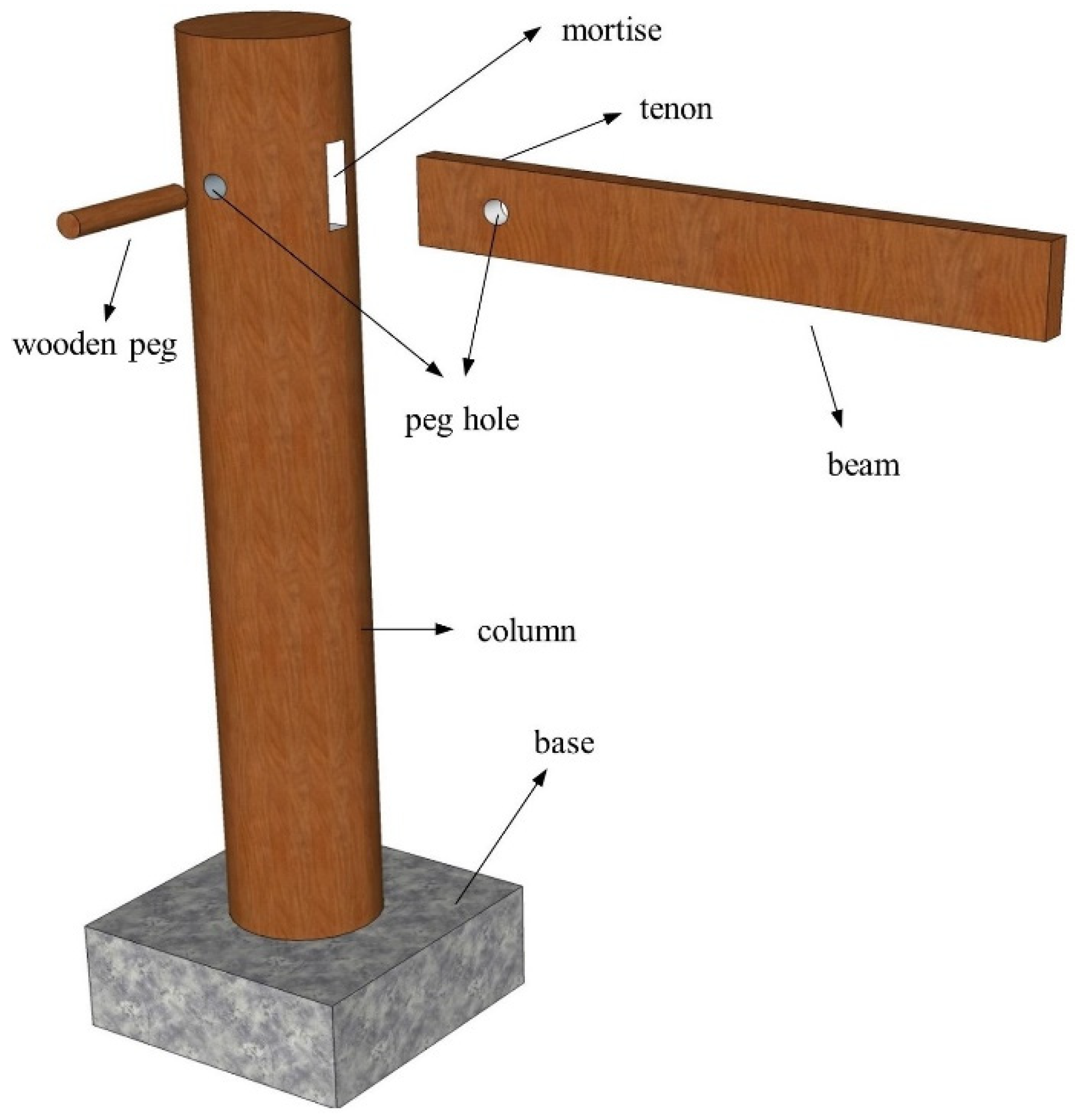
2.1. Construction of the SMTJ/WP
2.2. Stress Mechanism of the SMTJ/WP
3. Rotational Moment–Rotation Relationship of the SMTJ/WP
3.1. Basic Assumptions
- The wooden peg is assumed to be a rigid body, and the extrusion deformation of the contact surface between the tenon and the wooden peg is neglected, i.e., the tenon rotates with the wooden peg as the center during the stressing process.
- The influence of the interaction force between the peg and the peg hole of the beam on the bending moment is ignored. Since the pressure of the peg passes through the center of the peg, and the force arm from the friction in the tangential direction of the outer edge of the peg to the center of the peg is generally 5–15 mm, which is much smaller than other sizes, the contribution of the friction to the bending moment is small, and so the influence of the interaction force between the peg and the peg hole of the beam on the bending moment is not considered in the derivation of the theoretical model.
- When the tenon and the mortise compress against each other, the mortise is compressed parallel to the grain, while the tenon is compressed perpendicular to the grain. According to Ref. [11] and the material property test, the compression elastic modulus of wood along the grain is ten times more than that of wood perpendicular to the grain. Therefore, the compression deformation of the mortise is ignored and it is assumed that only the tenon undergoes compression deformation.
- Because the tenon is under uneven compression at multiple points, its bending deformation is relatively small, so its bending deformation is ignored based on the assumption of small deformation [11].
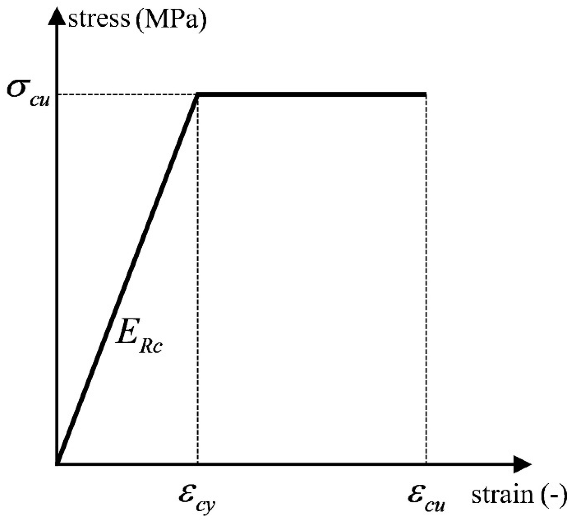
- The longitudinal grain direction refers to the direction of the beam length and column height. During rotation, the main deformation occurs to the tenon, and the MTJ mainly depends on the compression force of wood perpendicular to the grain to provide the bending moment. Therefore, the derivation of a theoretical model is mainly based on the stress–strain relationship of wood perpendicular to the grain. As stress on the weakening segment slightly decreases, the constitutive relationship of wood under compression perpendicular to the grain is simplified to a bilinear constitutive model [17], as shown in Figure 5, and the stress–strain relationship is assumed to follow Hooke’s law [22].
- The friction at the lateral contact surface between the tenon and the mortise is assumed to be 0. According to Reference [12], the lateral friction of the dovetail tenon contributes little to the moment of the joint, and the lateral restraint of the straight tenon is less than that of the dovetail tenon, so the influence of lateral friction can be neglected in the mechanical model.
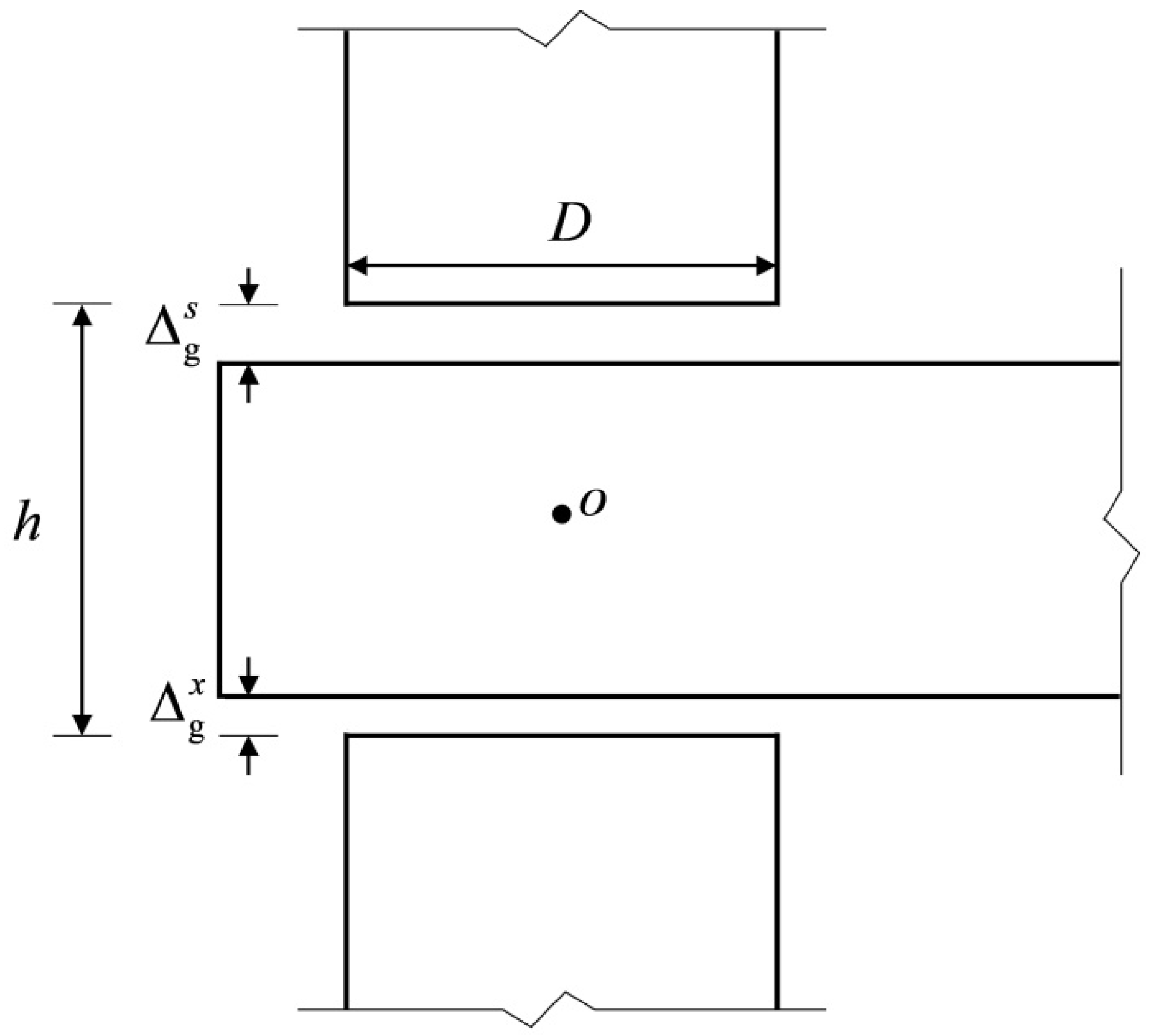
3.2. Derivation of the Theoretical Moment Model for the SMTJ/WP
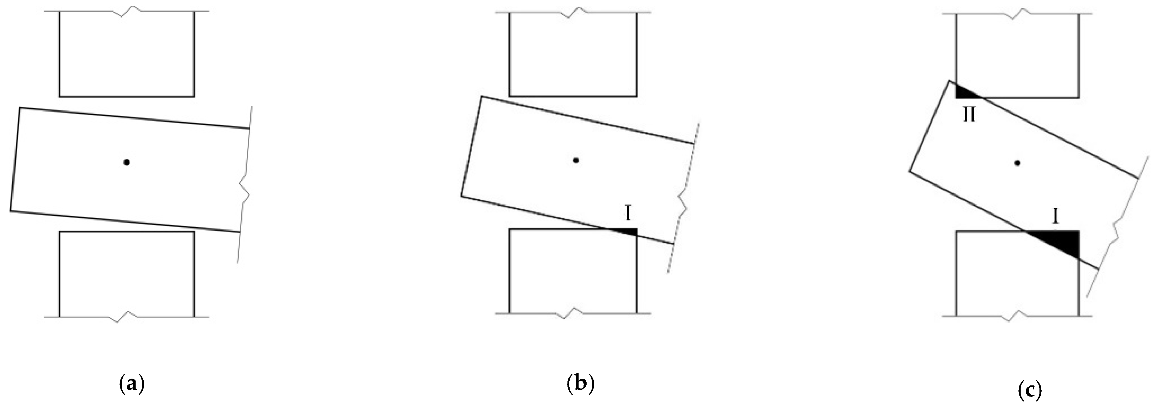
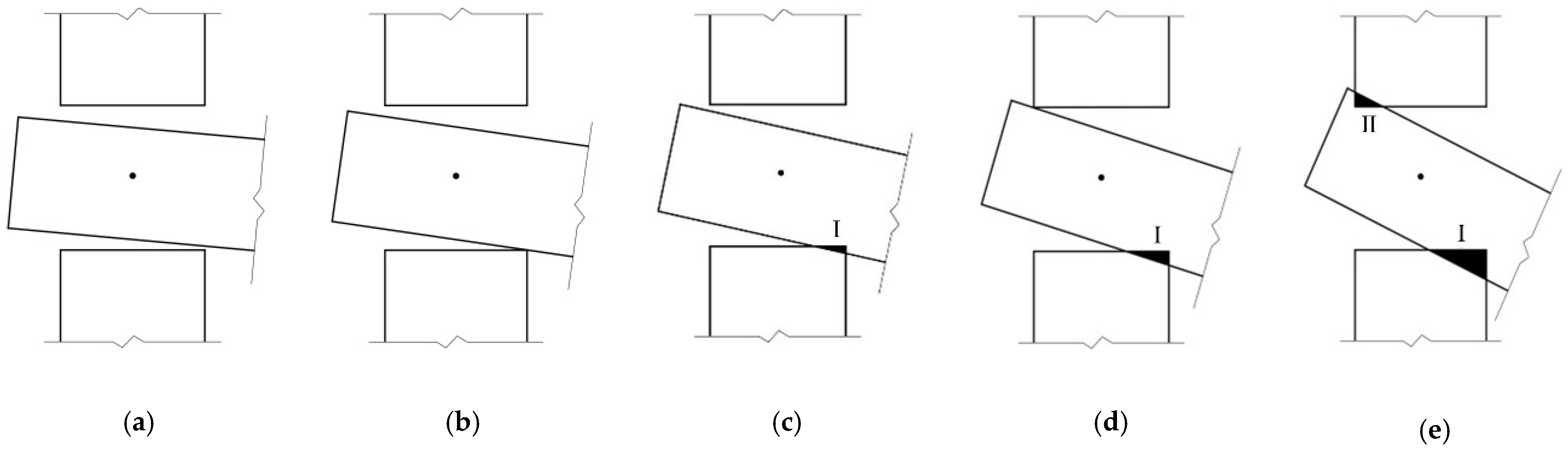
3.2.1. Working States of the SMTJ/WP
3.2.2. Determination of Working States
- 1.
- 2.
3.2.3. Theoretical Moment Model of the SMTJ/WP
- 1.
- Free rotation
- 2.
- Compression state
- (a)
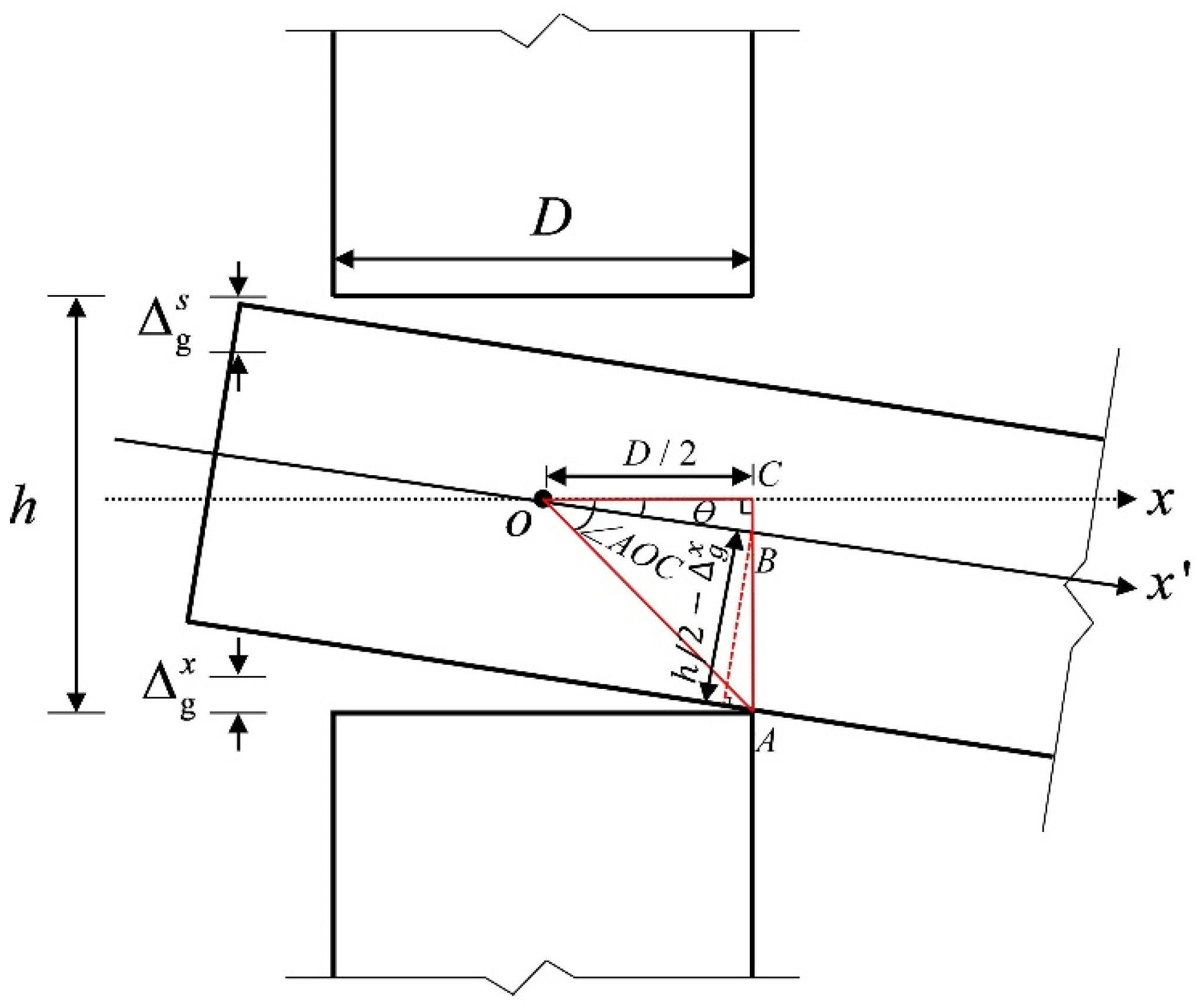
- Geometric relations
- (b)
- Physical conditions in the elastic state
- (c)
- Conditions for determining elasto-plasticity
- (1)
- Condition for determining the plastic state in region I
- (2)
- Condition for determining the plastic state in region II
- (d)
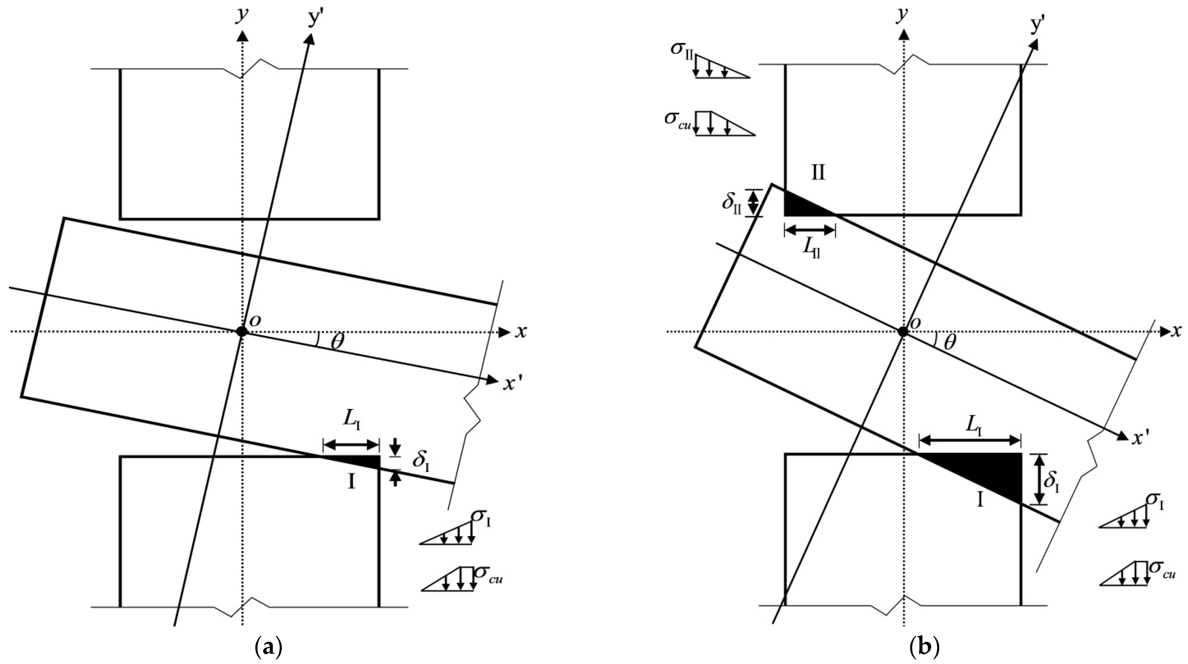
- Elastoplastic stage
- (1)
- Elastoplasticity of region I
- (2)
- Elastoplasticity of region II
- (e)
- Theoretical moment-rotation model of the joint
- (1)
- When
- (2)
- When
4. Experimental Verification
4.1. Test Overview and Specimen Design
4.2. Loading Protocol
4.3. Material Property Parameters
4.4. Test Phenomenon and Failure Mode
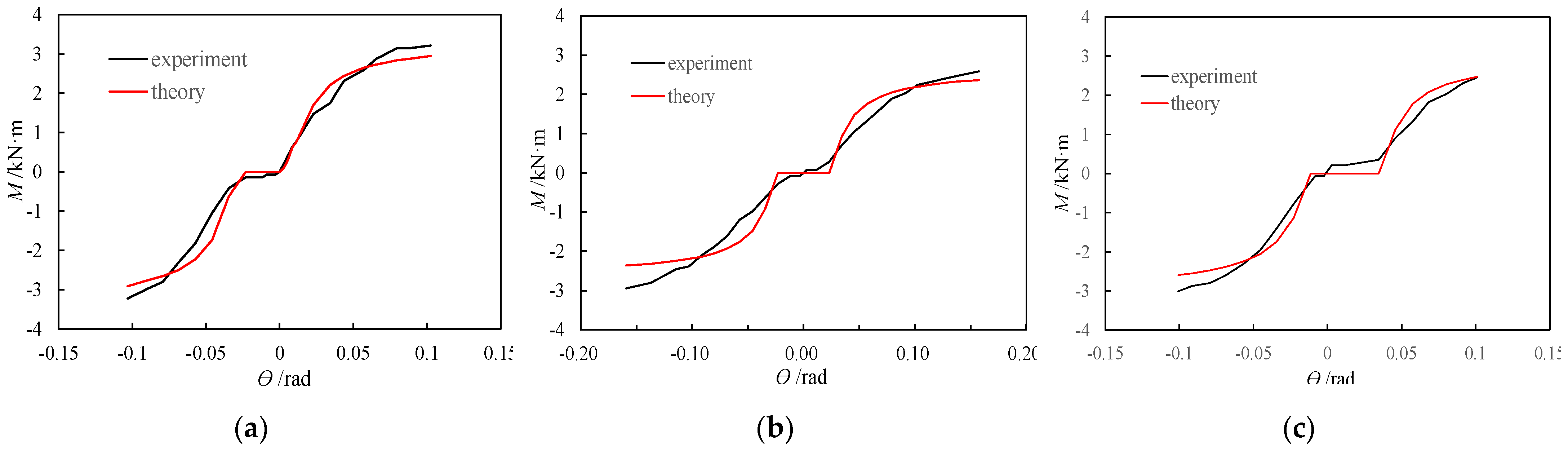
4.5. Theoretical Model Validation
5. Analysis of the Influence of the Parameters
5.1. Influence of Beam Height
5.2. Influence of Column Diameter
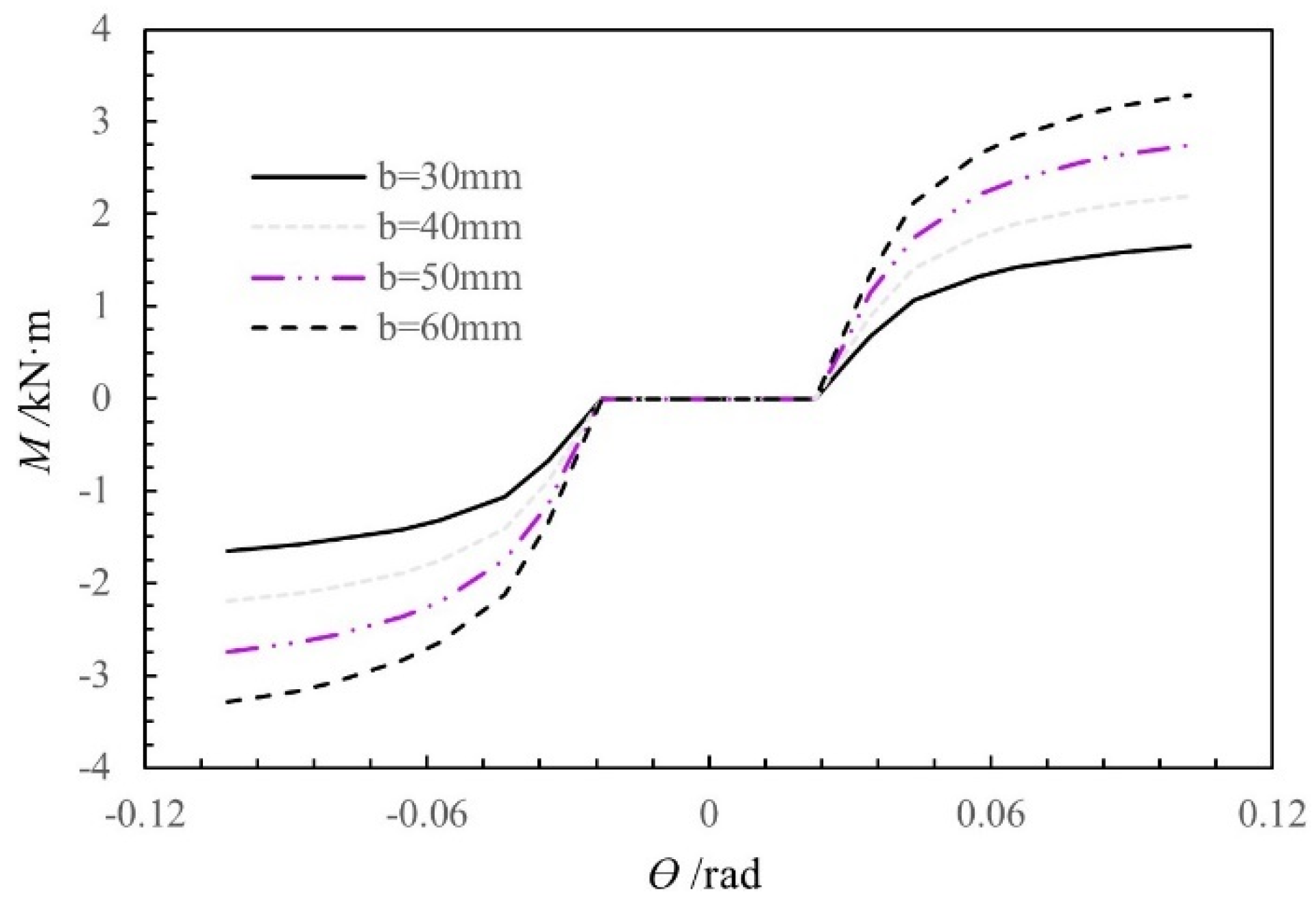
5.3. Influence of Beam Width
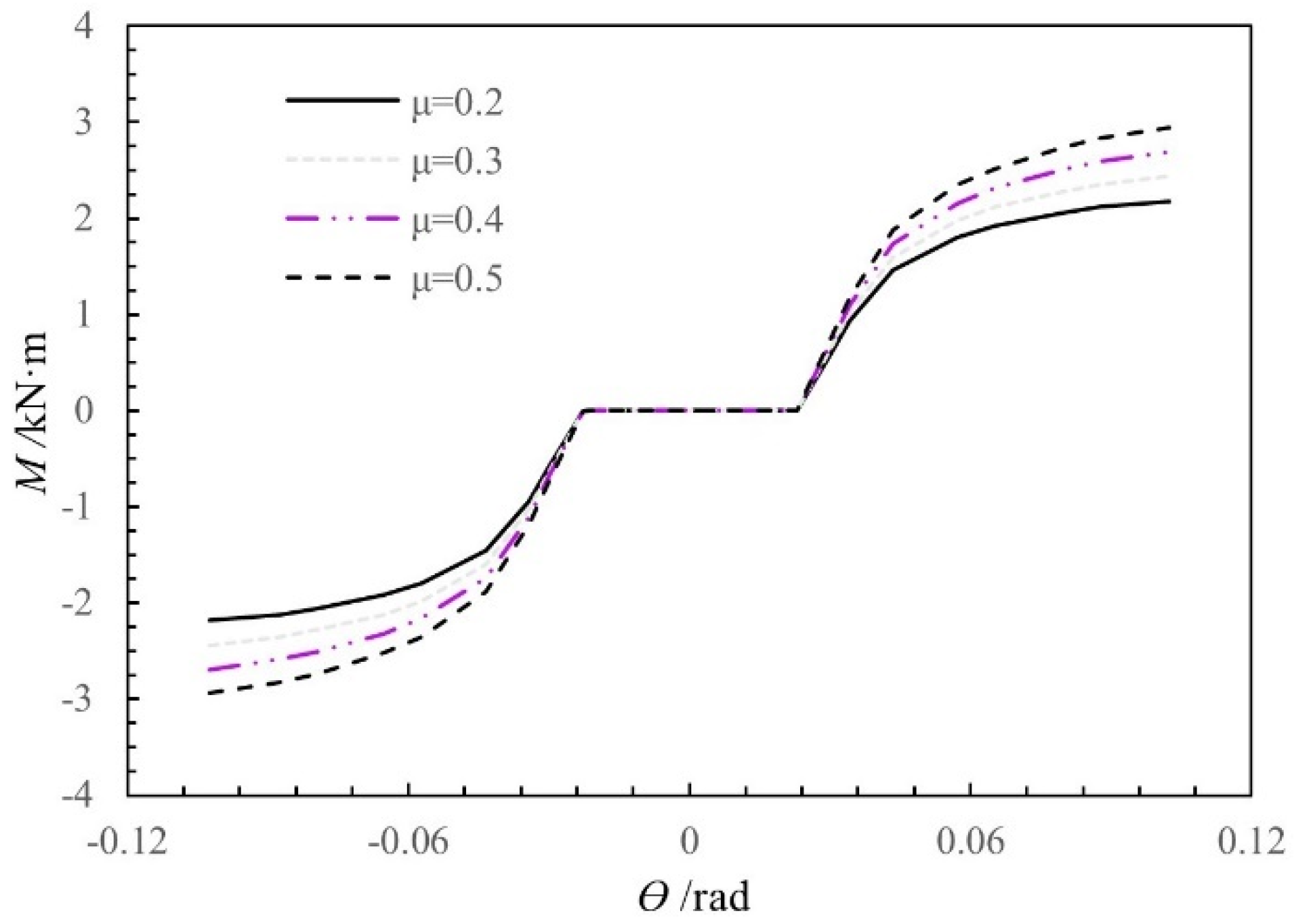
5.4. Influence of Sliding Friction Coefficient μ
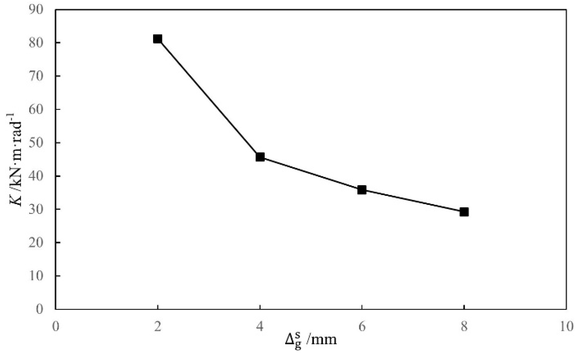
5.5. Influence of the Gap between the Tenon and the Mortise
6. Conclusions
- (1)
- The mechanical behavior of a SMTJ/WP involving a gap is closely related to the working states of the joint. According to the comparison between the rotation angle corresponding to the critical state II and the critical rotation angle for region Ι to enter the plastic state, the judgment criteria of the working state of the joint in two cases are obtained. For the first case, the joint has only one working state in compression state Ι; that is, the elastic compression state of region Ι. For the second case, two working states in compression state Ι, namely, the elastic compression and elastoplastic compression states, occur in region Ι successively.
- (2)
- The theoretical moment–rotation model of the SMTJ/WP involving a gap is proposed for different working states. Compared with the experimental results, the theoretical calculation results are generally consistent, indicating the validity of the theoretical calculation method for the SMTJ/WP.
- (3)
- According to the theoretical model, the analysis of the factors affecting the M-Ɵ relationship of the SMTJ/WP showed that both the rotational stiffness and the moment of the joint tend to increase as the beam width increases. Before the joint yields, the change in the beam height has no significant influence on the moment and rotational stiffness; after the joint yields, both the rotational stiffness and the moment increase as the beam height increases.
- (4)
- Furthermore, the derived model indicates that the increase in the column diameter leads to an increase in both the initial stiffness and the moment of the joint and a decrease in its free rotation, while the gap between the tenon and the mortise has the opposite influence on the initial stiffness, moment, and free rotation. The rotational stiffness and moment of the SMTJ/WP increase as the sliding friction coefficient increases, but the increase is larger after the joint yields than before.
Author Contributions
Funding
Institutional Review Board Statement
Informed Consent Statement
Data Availability Statement
Conflicts of Interest
References
- Ding, L.; Wang, Z.Q.; Yu, M.H. Dynamic characteristics and seismic response analysis of the wooden structure of the drum tower in Xi′an. J. Xian Jiaotong Univ. 2003, 37, 986–988. [Google Scholar]
- Landa-Ruiz, L.; Baltazar-Zamora, M.A.; Bosch, J.; Ress, J.; Santiago-Hurtado, G.; Moreno-Landeros, V.M.; Márquez-Montero, S.; Méndez, C.T.; Borunda, A.; Juárez-Alvarado, C.A.; et al. Electrochemical Corrosion of Galvanized Steel in Binary Sustainable Concrete Made with Sugar Cane Bagasse Ash (SCBA) and Silica Fume (SF) Exposed to Sulfates. Appl. Sci. 2021, 11, 2133. [Google Scholar] [CrossRef]
- Xiong, C.; Zheng, J.; Xu, L.; Cen, C.; Zheng, R.; Li, Y. Multiple-Input Convolutional Neural Network Model for Large-Scale Seismic Damage Assessment of Reinforced Concrete Frame Buildings. Appl. Sci. 2021, 11, 8258. [Google Scholar] [CrossRef]
- Miani, M.; Di Marco, C.; Frappa, G.; Pauletta, M. Effects of Dissipative Systems on the Seismic Behavior of Irregular Buildings—Two Case Studies. Buildings 2020, 10, 202. [Google Scholar] [CrossRef]
- Lai, J.; Cai, J.; Chen, Q.-J.; He, A.; Wei, M.-Y. Influence of Crack Width on Chloride Penetration in Concrete Subjected to Alternating Wetting-Drying Cycles. Materials 2020, 13, 3801. [Google Scholar] [CrossRef]
- Xie, Q.F.; Zheng, P.J.; Cui, Y.Z.; Qian, C.Y. Experimental study on seismic behavior of straight mortise-tenon joints of ancient timber buildings. Earthq. Eng. Eng. Dyn. 2015, 35, 232–241. [Google Scholar]
- Bulleit, W.M.; Sandberg, L.B.; Drewek, M.W. Behavior and modeling of wood-pegged timber frames. J. Struct. Eng. 1999, 125, 3–9. [Google Scholar] [CrossRef]
- Feio, A.O.; Lourenço, P.B.; Machado, J.S. Testing and modeling of a traditional timber mortise and tenon joint. Mater. Struct. 2014, 47, 213–225. [Google Scholar] [CrossRef] [Green Version]
- Pang, S.J.; Oh, J.K.; Park, J.S.; Park, C.Y.; Lee, J.J. Moment-carrying capacity of dovetailed mortise and tenon joints with or without beam shoulder. J. Struct. Eng. 2011, 137, 785–789. [Google Scholar] [CrossRef]
- Li, S.C.; Zhou, Z.C.; Luo, H.Z. Behavior of traditional Chinese mortise-tenon joints: Experimental and numerical insight for coupled vertical and reversed horizontal loads. J. Build. Eng. 2020, 30, 101257. [Google Scholar] [CrossRef]
- Xie, Q.F.; Wang, L.; Zheng, P.J. Theoretical analysis on moment-rotation relationship of strait mortise-tenon joints for Chinese traditional wooden buildings. J. Hunan Univ. Nat. Sci. Ed. 2017, 44, 111–117. [Google Scholar]
- Pan, Y.; Wang, C.; Tang, L.N. Study on mechanical model of strait-tenon joints in ancient timber structures. Eng. Mech. 2015, 32, 82–89. [Google Scholar]
- Pan, Y.; An, R.B.; Wang, X.Y.; Guo, R. Study on mechanical model of through-tenon joints in ancient timber structures. Chin. Civil. Eng. J. 2020, 53, 62–82. [Google Scholar]
- Xie, Q.F.; Wang, L.; Zheng, P.J.; Zhang, L.P.; Hu, W.B. Rotational behavior of degraded traditional mortise-tenon joints: Experimental tests and hysteretic model. Int. J. Architect. Herit. 2018, 12, 125–136. [Google Scholar] [CrossRef]
- Chang, W.S.; Hsu, M.F.; Komatsu, K. Rotational performance of traditional Nuki joints with gap I: Theory and verification. J. Wood. Sci. 2006, 52, 58–62. [Google Scholar] [CrossRef]
- Xue, J.Y.; Qi, L.J.; Dong, J.S.; Xu, D. Analytical investigation on moment-rotation relationship of through-tenon joints with looseness in ancient timber buildings. Earthq. Struct. 2018, 14, 241–248. [Google Scholar]
- He, J.X.; Yu, P.; Wang, J. Theoretical model of bending moment for the penetrated mortise-tenon joint involving gaps in traditional timber structure. J. Build. Eng. 2021, 42, 103102. [Google Scholar] [CrossRef]
- Keita, O.; Yasutoshi, S.; Mariko, Y. Theoretical estimation of the mechanical performance of traditional mortise-tenon joint involving a gap. J. Wood. Sci. 2016, 62, 242–250. [Google Scholar]
- Suzuki, Y.; Maeno, M. Structural mechanism of traditional wooden frames by dynamic and static tests. Struct. Contr. Health Monit. 2006, 13, 508–522. [Google Scholar] [CrossRef]
- Guan, Z.W.; Kitamori, A.; Komatsu, K. Experimental study and finite element modelling of Japanese ‘‘Nuki’’ joints part two: Racking resistance subjected to different wedge configurations. Eng. Struct. 2008, 30, 2041–2049. [Google Scholar] [CrossRef]
- Zhang, X.C.; Dai, W.Q.; Xue, J.Y. Theoretical Analysis on Moment-Rotation Relationship of Through-Tenon Joint with Gap. J. Hunan Univ. Nat. Sci. Ed. 2018, 45, 126–133. [Google Scholar]
- Chang, W.S.; Hsu, M.F.; Komatsu, K. Rotational performance of traditional Nuki joints with gapⅡ: The behavior of butted Nuki joint. J. Wood Sci. 2007, 52, 401–407. [Google Scholar] [CrossRef]
- Li, X.; Zhao, J.; Ma, G. Experimental study on the seismic performance of a double-span traditional timber frame. Eng. Struct. 2015, 98, 141–150. [Google Scholar] [CrossRef]
- Chen, C.C.; Qiu, H.X.; Bao, T.N.; Hao, X.H. Experimental study on positive and reverse flexural behavior of asymmetric mortise-tenon joints. J. Southeast Univ. Nat. Sci. Ed. 2014, 44, 1224–1229. [Google Scholar]
- Gao, Y.L.; Tao, Z. Low-cycle reversed loading tests study on typical mortise-tenon joints of traditional timber building based on friction mechanism. J. Build. Struct. 2015, 36, 139–145. [Google Scholar]
- Yin, S.C. Wood Science, 2nd ed.; China Forestry Press: Beijing, China, 1996. [Google Scholar]


| Specimen | h/mm | b/mm | ||
|---|---|---|---|---|
| BS1 | 160 | 50 | 2 | 1 |
| BS2 | 160 | 40 | 2 | 2 |
| BS3 | 130 | 50 | 2 | 2 |
| Experimental Items | Sample Size | Average Value/MPa | Standard Deviation/MPa | Variation Coefficient % | Moisture Content % |
|---|---|---|---|---|---|
| Compressive strength along the grain | 30 mm × 20 mm × 20 mm | 31.13 | 0.91 | 2.93 | 11.3 |
| Compressive strength perpendicular to the grain | 30 mm × 20 mm × 20 mm | 4.33 | 0.69 | 15.83 | 12.4 |
| Tensile strength along the grain | 370 mm × 20 mm × 15 mm (The middle section size is 15 mm × 5 mm) | 75.27 | 6.97 | 9.26 | 11.7 |
| Elastic modulus along the radial | 60 mm × 20 mm × 20 mm | 1073.96 | 109.53 | 10.2 | 12.2 |
| Elastic modulus along the grain | 60 mm × 20 mm × 20 mm | 11430.84 | 805.82 | 7.05 | 11.9 |
| Specimen | Mye/KN·m | Myc/KN·m | Myc/Mye | Mue/KN·m | Muc/KN·m | Muc/Mue |
|---|---|---|---|---|---|---|
| BS1 | 1.65 | 1.72 | 1.04 | 3.22 | 2.93 | 0.91 |
| BS2 | 1.02 | 0.92 | 0.90 | 2.77 | 2.36 | 0.85 |
| BS3 | 1.16 | 1.13 | 0.97 | 2.73 | 2.53 | 0.93 |
Publisher’s Note: MDPI stays neutral with regard to jurisdictional claims in published maps and institutional affiliations. |
© 2022 by the authors. Licensee MDPI, Basel, Switzerland. This article is an open access article distributed under the terms and conditions of the Creative Commons Attribution (CC BY) license (https://creativecommons.org/licenses/by/4.0/).
Share and Cite
Hu, B.; Cai, J.; Yang, C. Theoretical Model of Bending Moment for Straight Mortise-and-Tenon Joints with Wooden Pegs Involving a Gap. Materials 2022, 15, 1835. https://doi.org/10.3390/ma15051835
Hu B, Cai J, Yang C. Theoretical Model of Bending Moment for Straight Mortise-and-Tenon Joints with Wooden Pegs Involving a Gap. Materials. 2022; 15(5):1835. https://doi.org/10.3390/ma15051835
Chicago/Turabian StyleHu, Bin, Jian Cai, and Chun Yang. 2022. "Theoretical Model of Bending Moment for Straight Mortise-and-Tenon Joints with Wooden Pegs Involving a Gap" Materials 15, no. 5: 1835. https://doi.org/10.3390/ma15051835
APA StyleHu, B., Cai, J., & Yang, C. (2022). Theoretical Model of Bending Moment for Straight Mortise-and-Tenon Joints with Wooden Pegs Involving a Gap. Materials, 15(5), 1835. https://doi.org/10.3390/ma15051835