

Strain Hardening of Polypropylene Microfiber Reinforced Composite Based on Alkali-Activated Slag Matrix

 , , ,
, , ,
Abstract
:1. Introduction
2. Materials and Methods
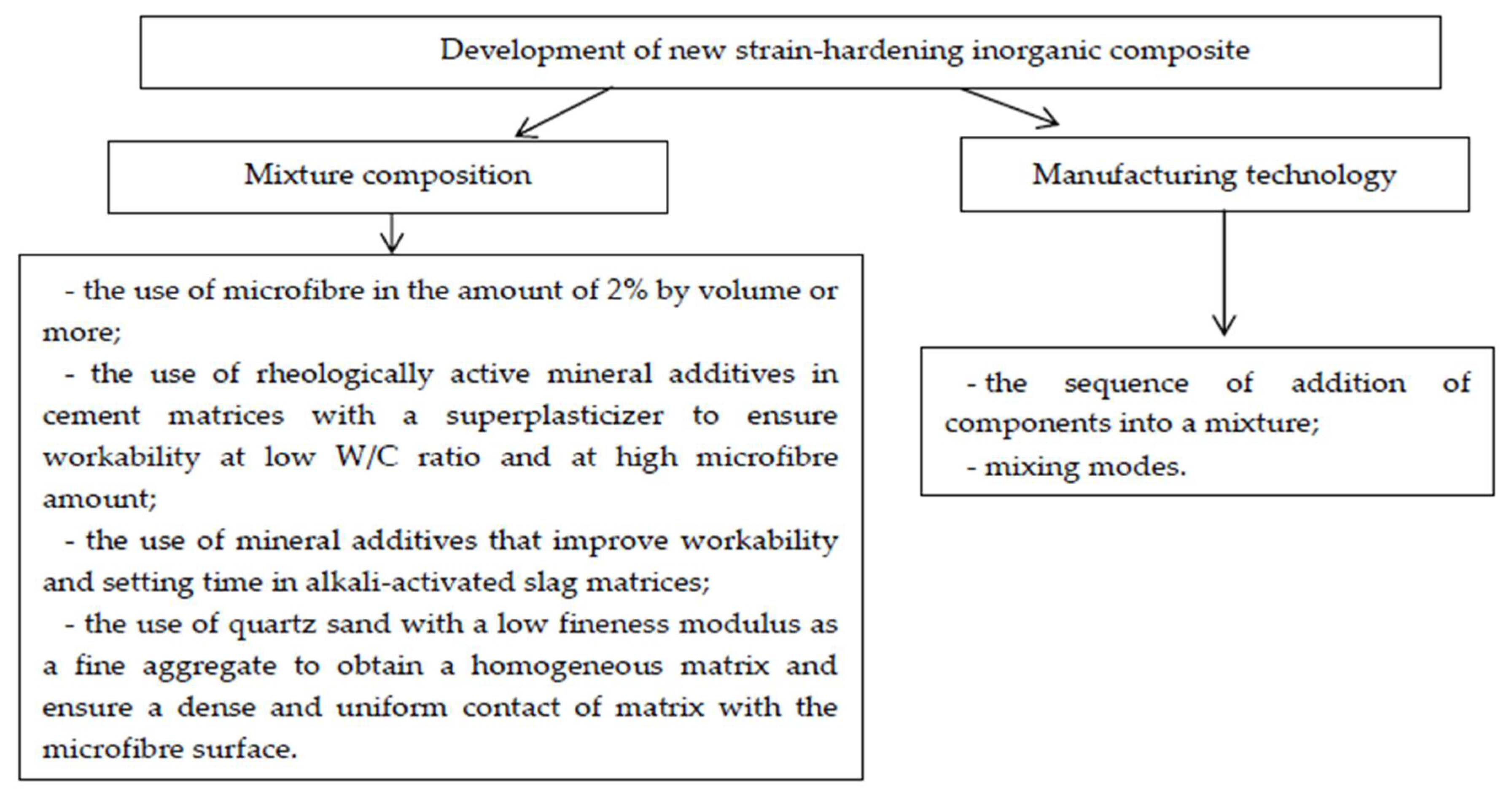
2.1. Materials and Mixture Composition
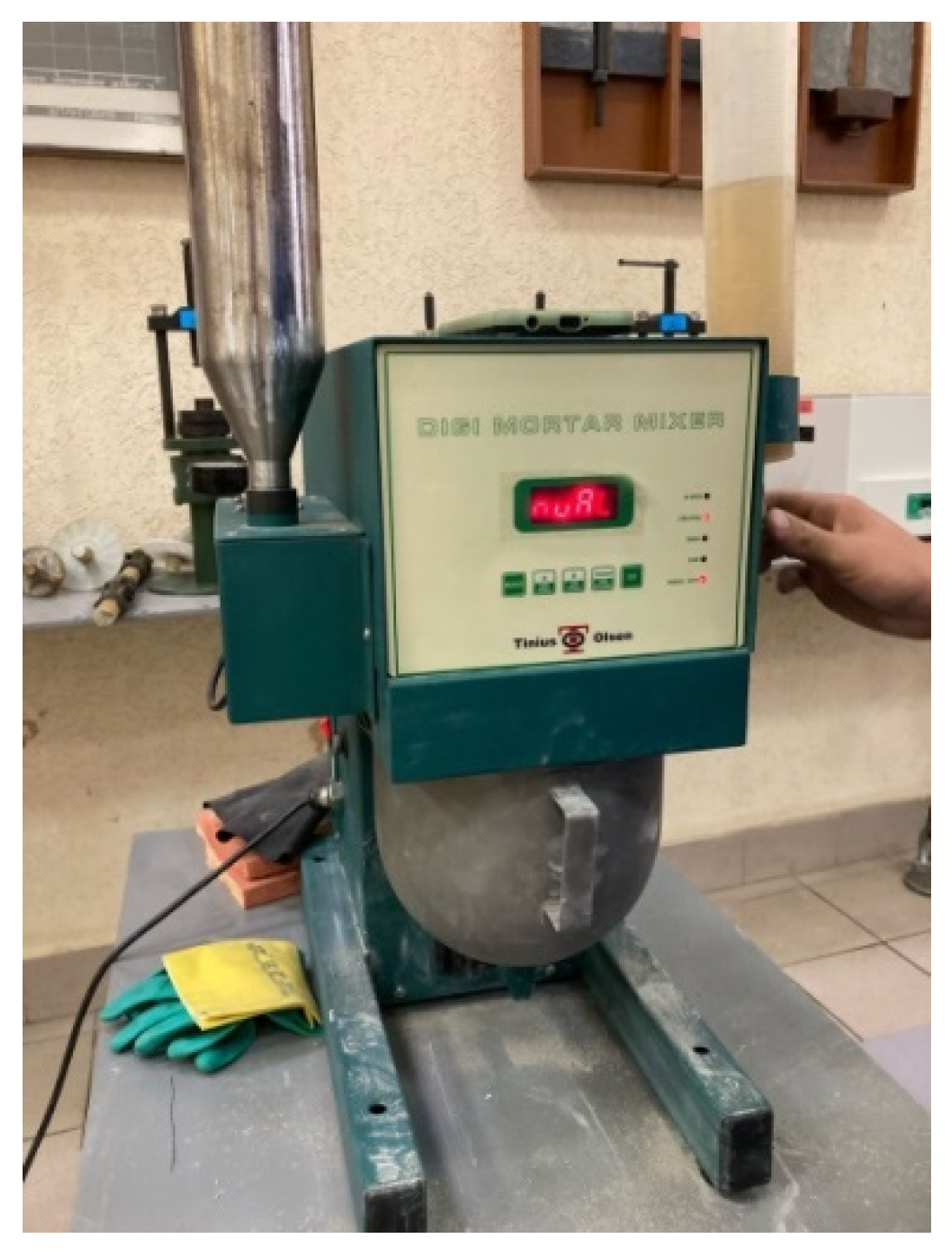
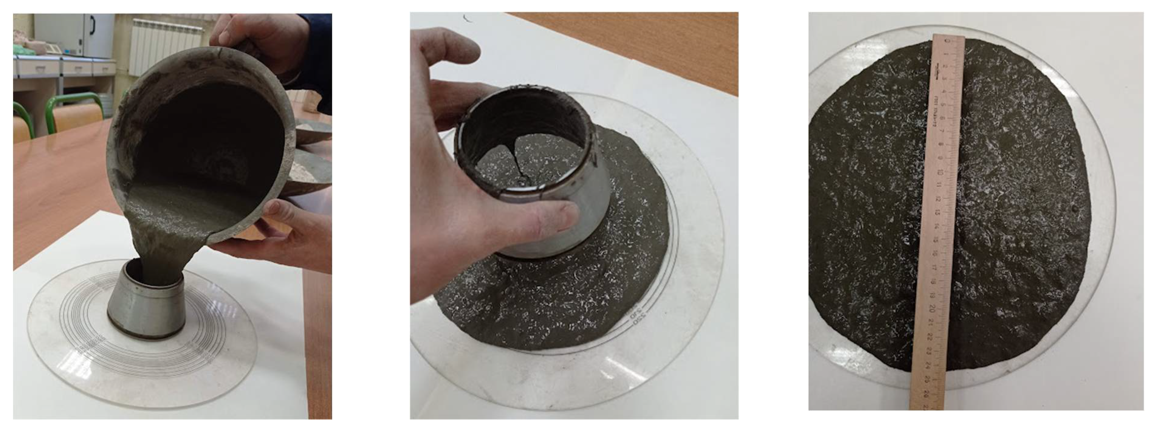
2.2. Manufacturing Procedure
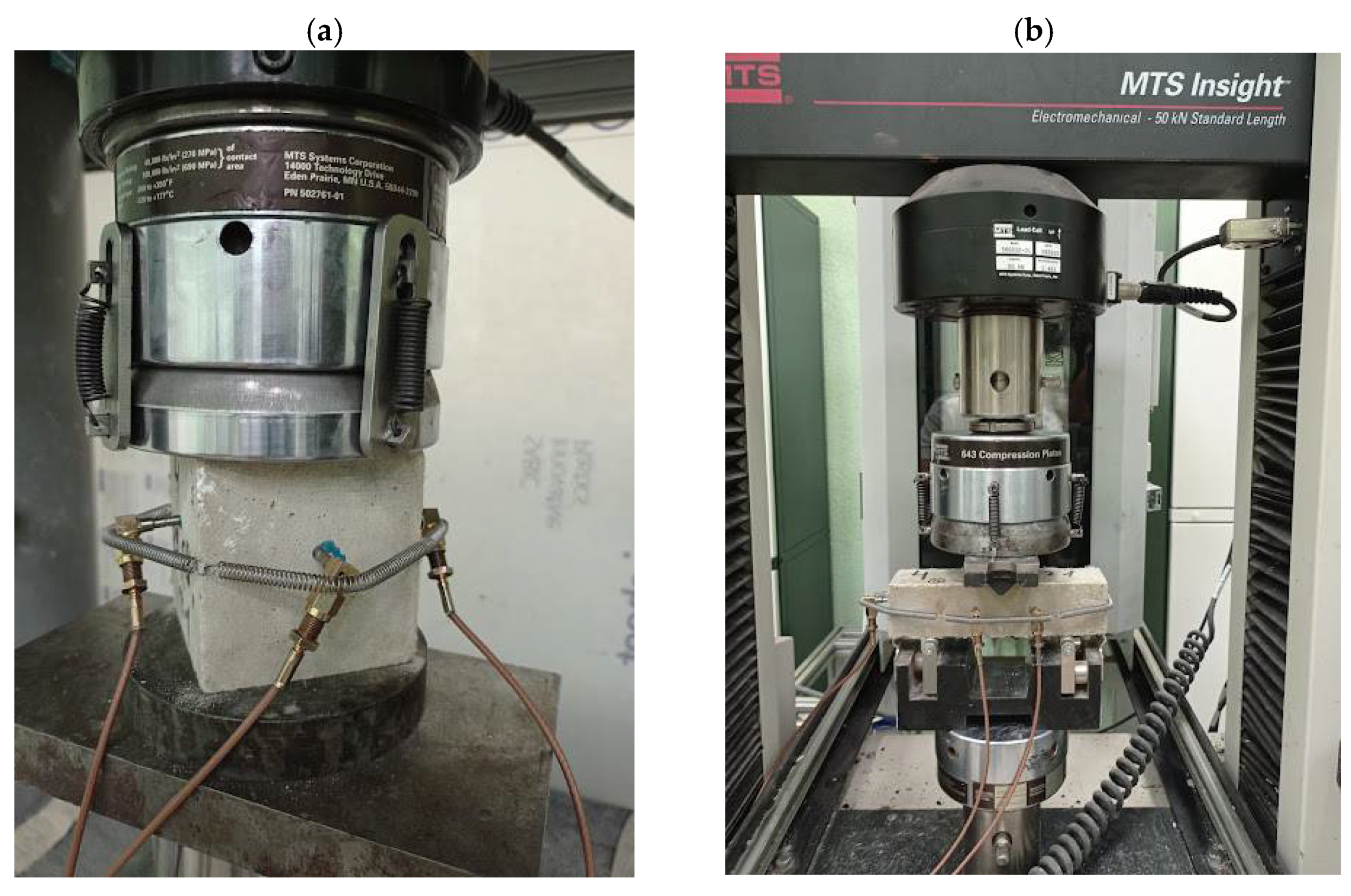
2.3. Experimental Devices and Procedures
2.3.1. Mechanical Properties
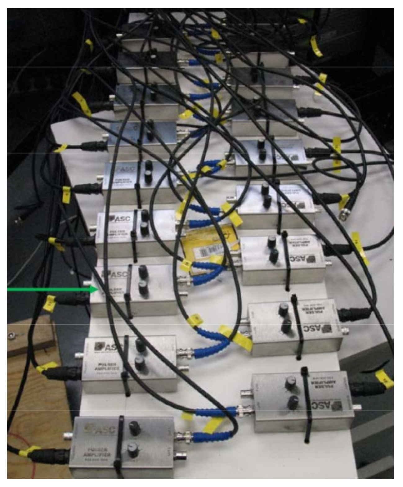
2.3.2. Acoustic Emission (AE)
3. Results
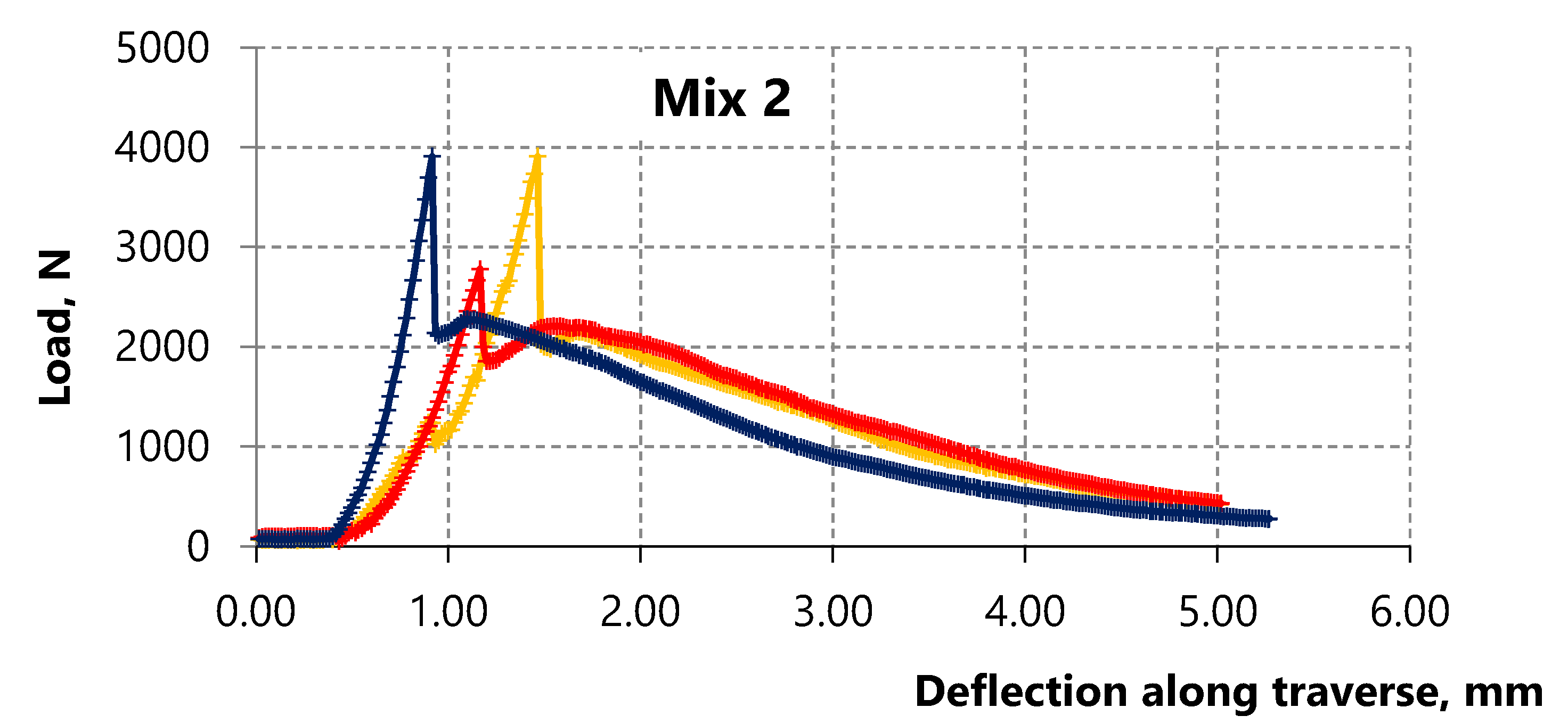
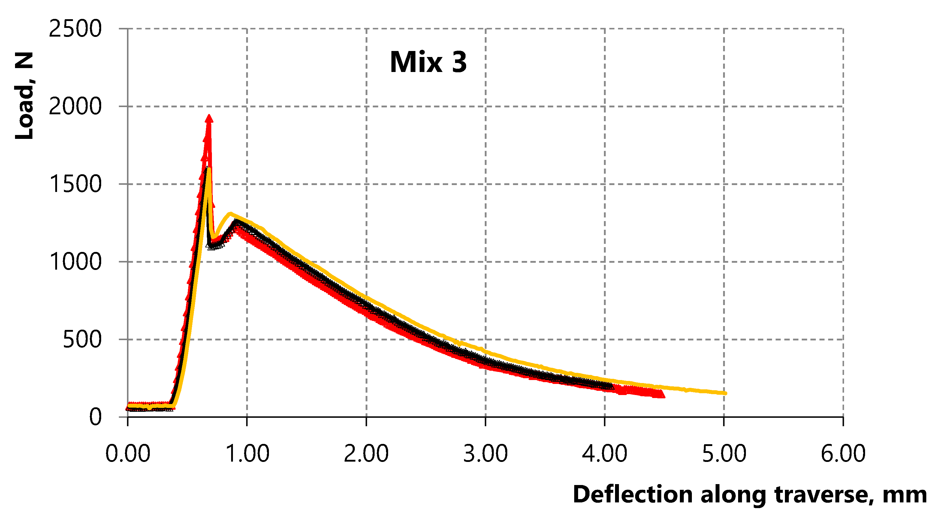
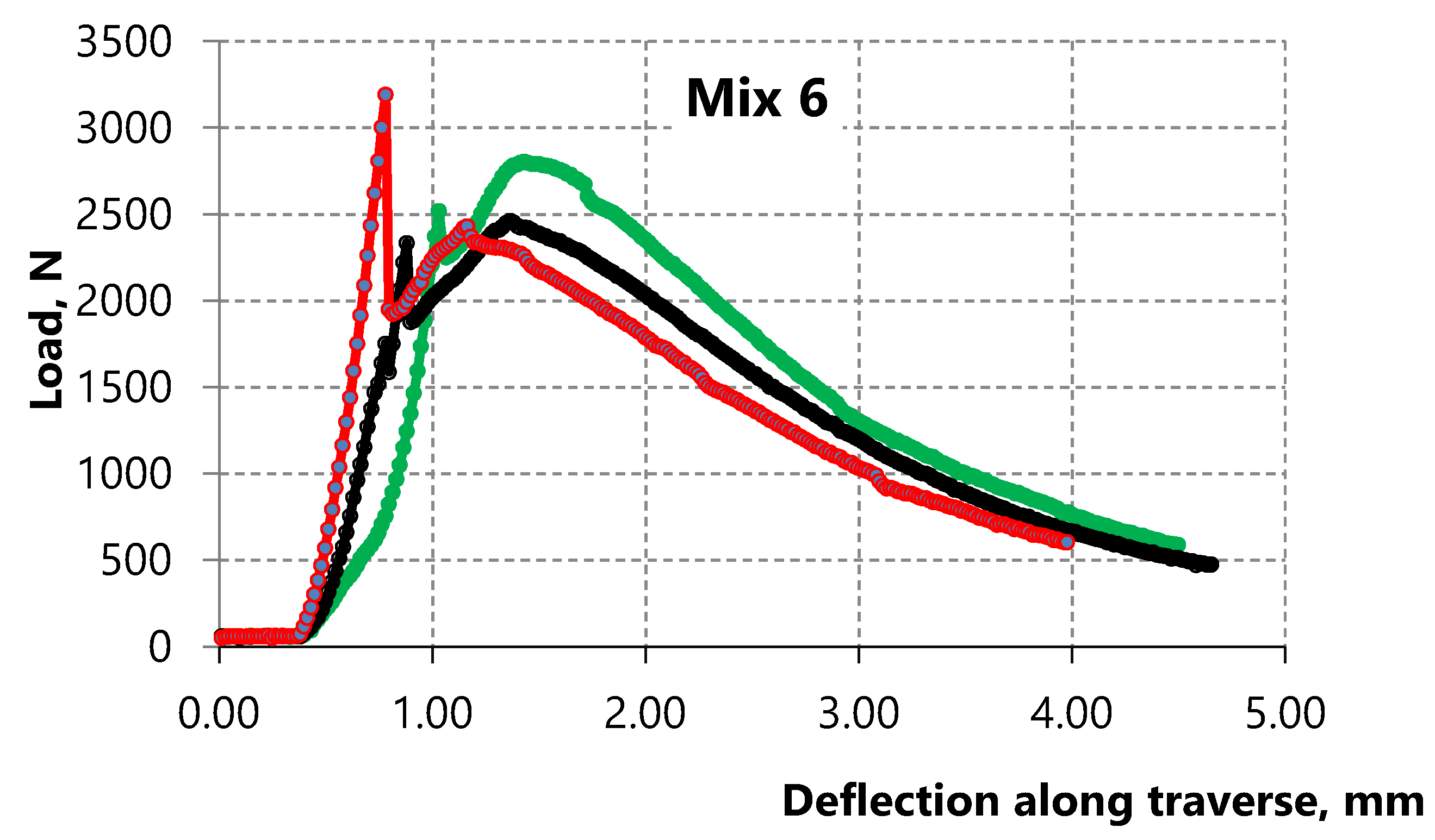
3.1. Compressive Strength and Tensile Strength in Bending
3.2. AE Measurements
4. Discussion
- -
- fibers in a large amount contribute to the appearance of strain-hardening of material after the formation of microcracks under external loading;
- -
- mechanical properties of lining increase under complex loading since reinforcement is carried out in all directions of walling;
- -
- residual strength of fiber-reinforced spray concrete is higher than the strength of ordinary concrete;
- -
- connectivity of sprayed concrete with the rock contour increases since there are no voids that can form between the rock contour and the sprayed concrete in the case of mesh reinforcement;
- -
5. Conclusions
Author Contributions
Funding
Institutional Review Board Statement
Informed Consent Statement
Data Availability Statement
Conflicts of Interest
References
- Curosu, I.; Mechtcherine, V.; Millon, O. Effect of fiber properties and matrix composition on the tensile behavior of strain-hardening cement-based composites (SHCCs) subject to impact loading. Cem. Concr. Res. 2016, 82, 23–35. [Google Scholar] [CrossRef]
- Heravi, A.A.; Mosig, O.; Tawfik, A.; Curbach, M.; Mechtcherine, V. An experimental investigation of the behavior of strain-hardening cement-based composites (SHCC) under impact compression and shear loading. Materials 2020, 13, 4514. [Google Scholar] [CrossRef] [PubMed]
- Junger, D.; Storm, J.; Müller, S.; Kaliske, M.; Mechtcherine, V. Increasing the Fatigue Resistance of Strain-Hardening Cement-Based Composites (SHCC) by Experimental-Virtual Multi-Scale Material Design. Materials 2021, 14, 5634. [Google Scholar] [CrossRef] [PubMed]
- Klyuev, S.V.; Khezhev, T.A.; Pukharenko, Y.V.; Klyuev, A.V. Fibers and their properties for concrete reinforcement. Mater. Sci. Forum. 2019, 945, 125–130. [Google Scholar]
- Iskhakov, I.; Frolov, I.; Ribakov, Y. Experimental Investigation of Concrete Transverse Deformations at Relatively High Loading Rates for Interpretation of High Strength Concrete Behavior. Appl. Sci. 2021, 11, 8460. [Google Scholar] [CrossRef]
- Karasev, M.A.; Sotnikov, R.O. Prediction of the stress state of the shotcreting support under repeated seismic load. J. Min. Inst. 2021, 251, 626–638. [Google Scholar] [CrossRef]
- Tien, N.T.; Karasev, M.A.; Vilner, M.A. Study of the stress-strain state in the sub-rectangular tunnel. Lect. Notes Civ. Eng. 2020, 62, 383–388. [Google Scholar]
- Pang, M.; Shi, S.; Hu, H.; Lou, T. Flexural Behavior of Two-Span Continuous CFRP RC Beams. Materials 2021, 14, 6746. [Google Scholar] [CrossRef]
- Kim, M.J.; Chun, B.; Choi, H.J.; Shin, W.; Yoo, D.Y. Effects of supplementary cementitious materials and curing condition on mechanical properties of ultra-high-performance, strain-hardening cementitious composites. Appl. Sci. 2021, 11, 2394. [Google Scholar] [CrossRef]
- Yang, E.H.; Li, V.C. Strain-rate effects on the tensile behavior of strain-hardening cementitious composites. Constr. Build. Mater. 2014, 52, 96–104. [Google Scholar] [CrossRef]
- Junger, D.; Müller, S.; Mechtcherine, V. Rheological Model to Describe the Cyclic Load-Bearing Behaviour of Strain-Hardening Cement-Based Composites (SHCC). Materials 2021, 14, 6444. [Google Scholar] [CrossRef] [PubMed]
- Li, V.C. On engineered cementitious composites (ECC) a review of the material and its applications. J. Adv. Concr. Technol. 2003, 1, 215–230. [Google Scholar] [CrossRef] [Green Version]
- Iskhakov, I.; Ribakov, Y. Structural phenomenon based theoretical model of concrete tensile behavior at different stress-strain conditions. J. Build. Eng. 2021, 33, 101594. [Google Scholar] [CrossRef]
- Klyuev, S.V.; Bratanovskiy, S.N.; Trukhanov, S.V.; Manukyan, H.A. Strengthening of concrete structures with composite based on carbon fiber. J. Comput. Theor. Nanosci. 2019, 16, 2810–2814. [Google Scholar] [CrossRef]
- Mailyan, L.R.; Beskopylny, A.N.; Meskhi, B.; Shilov, A.V.; Stel’makh, S.A.; Shcherban, E.M.; Smolyanichenko, A.S.; El’shaeva, D. Improving the structural characteristics of heavy concrete by combined disperse reinforcement. Appl. Sci. 2021, 11, 6031. [Google Scholar] [CrossRef]
- Xu, L.Y.; Huang, B.T.; Li, V.C.; Dai, J.G. High-strength high-ductility Engineered/Strain-Hardening Cementitious Composites (ECC/SHCC) incorporating geopolymer fine aggregates. Cem. Concr. Compos. 2021, 125, 104296. [Google Scholar] [CrossRef]
- Mechtcherine, V.; Millon, O.; Butler, M.; Thoma, K. Mechanical behaviour of strain hardening cement-based composites under impact loading. Cem. Concr. Compos. 2011, 33, 1–11. [Google Scholar] [CrossRef]
- Serag, M.I.; Yasien, A.M.; El-Feky, M.S.; Elkady, H. Effect of nano silica on concrete bond strength modes of failure. Int J Geomate 2017, 12, 2892–2899. [Google Scholar] [CrossRef]
- Yasien, A.M.; Bassuoni, M.T.; Abayou, A.; Ghazy, A. Nano-Modified Concrete as Repair Material in Cold Weather. ACI Mater. J. 2021, 118, 149–160. [Google Scholar]
- Kazanskaya, L.F.; Isakovsky, V.I.; Fadeeva, S.A. Technological Properties of Self-Compacting Concrete Mixtures with Ground Quartz Sand. Int. J. Innov. Technol. Explor. Eng. 2019, 8, 799–803. [Google Scholar]
- Kostyuk, T.; Vinnichenko, V.; Plugin, A.A.; Borziak, O.; Iefimenko, A. Physicochemical studies of the structure of energy-saving compositions based on slags. IOP Conf. Ser.: Mater. Sci. Eng. 2021, 1021, 12016. [Google Scholar] [CrossRef]
- Martauz, P.; Václavík, V.; Cvopa, B. The Influence of the Environment on the Properties of Hybrid Cement-Based Concrete with Steel and Air-Cooled Slags. Crystals 2021, 11, 1087. [Google Scholar] [CrossRef]
- Deshmukh, M.P.; Sarode, D.D. Bulk utilization of industrial waste (bauxite residue) of red mud concrete. J. Mech. Civ. Eng. 2014, 11, 1–3. [Google Scholar]
- Bowen, J.; Rossetto, H.L.; Kendall, K. Adhesion between silica surfaces due to hydrogen bonding. Surf. Topogr. Metrol. Prop. 2016, 4, 34001. [Google Scholar] [CrossRef] [Green Version]
- Klyuev, S.V.; Khezhev, T.A.; Pukharenko, Y.V.; Klyuev, A.V. To the question of fiber reinforcement of concrete. Mater. Sci. Forum. 2019, 945, 25–29. [Google Scholar]
- Zukowski, B.; de Andrade Silva, F.; Toledo Filho, R.D. Design of strain hardening cement-based composites with alkali treated natural curauá fiber. Cem. Concr. Compos. 2018, 89, 150–159. [Google Scholar] [CrossRef]
- Ahmad, J.; Zaid, O.; Aslam, F.; Shahzaib, M.; Ullah, R.; Alabduljabbar, H.; Khedher, K.M. A Study on the Mechanical Characteristics of Glass and Nylon Fiber Reinforced Peach Shell Lightweight Concrete. Materials 2021, 14, 4488. [Google Scholar] [CrossRef]
- Zaid, O.; Ahmad, J.; Siddique, M.S.; Aslam, F. Effect of incorporation of rice husk ash instead of cement on the performance of steel fibers reinforced concrete. Front. Mater. 2021, 8, 665625. [Google Scholar] [CrossRef]
- Muendecke, E.; Mechtcherine, V. Tensile behaviour of strain-hardening cement-based composites (SHCC) with steel reinforcing bars. Cem. Concr. Compos. 2020, 105, 103423. [Google Scholar] [CrossRef]
- Wang, L.; Rehman, N.U.; Curosu, I.; Zhu, Z.; Beigh, M.A.B.; Liebscher, M.; Mechtcherine, V. On the use of limestone calcined clay cement (LC3) in high-strength strain-hardening cement-based composites (HS-SHCC). Cem. Concr. Res. 2021, 144, 106421. [Google Scholar] [CrossRef]
- Shen, L.A.; Yu, W.; Li, L.; Zhang, T.; Abshir, I.Y.; Luo, P.; Liu, Z. Microorganism, Carriers, and Immobilization Methods of the Microbial Self-Healing Cement-Based Composites: A Review. Materials 2021, 14, 5116. [Google Scholar] [CrossRef] [PubMed]
- Plugin, A.A.; Pluhin, O.A.; Borziak, O.S.; Kaliuzhna, O.V. The Mechanism of a Penetrative Action for Portland Cement-Based Waterproofing Compositions. Lect. Notes Civ. Eng. 2020, 47, 34–41. [Google Scholar]
- Kilmartin-Lynch, S.; Saberian, M.; Li, J.; Roychand, R.; Zhang, G. Preliminary evaluation of the feasibility of using polypropylene fibres from COVID-19 single-use face masks to improve the mechanical properties of concrete. J. Clean. Prod. 2021, 296, 126460. [Google Scholar] [CrossRef] [PubMed]
- Vafaei, D.; Ma, X.; Hassanli, R.; Duan, J.; Zhuge, Y. Microstructural behaviour and shrinkage properties of high-strength fiber-reinforced seawater sea-sand concrete. Constr. Build. Mater. 2022, 320, 126222. [Google Scholar] [CrossRef]
- Lee, B.Y.; Li, V.C.; Kim, Y.Y. Polypropylene fiber-based strain-hardening cementitious composites. In Proceedings of the 2013 World Congress on Advances in Structural Engineering and Mechanics (ASEM13), Jeju, Korea, 8–12 September 2013; pp. 8–12. [Google Scholar]
- Pakravan, H.R.; Jamshidi, M. Tensile properties of strain-hardening cementitious composites containing polyvinyl-alcohol fibers hybridized with polypropylene fibers. J. Cent. South Univ. 2018, 25, 51–59. [Google Scholar] [CrossRef]
- Sun, C.; Zhang, J.; Yan, C.; Yin, L.; Wang, X.; Liu, S. Hydration characteristics of low carbon cementitious materials with multiple solid wastes. Constr. Build. Mater. 2022, 322, 126366. [Google Scholar] [CrossRef]
- Lesovik, V.S.; Ahmed, A.A.; Fediuk, R.S.; Kozlenko, B.; Amran, Y.H.M.; Alaskhanov, A.K.; Asaad, M.A.; Murali, G.; Uvarov, V.A. Performance investigation of demolition wastes-based concrete composites. Mag. Civ. Eng. 2021, 106, 74–83. [Google Scholar]
- Ghisellini, P.; Ncube, A.; D’Ambrosio, G.; Passaro, R.; Ulgiati, S. Potential Energy Savings from Circular Economy Scenarios Based on Construction and Agri-Food Waste in Italy. Energies 2021, 14, 8561. [Google Scholar] [CrossRef]
- Nguyen, H.; Carvelli, V.; Adesanya, E.; Kinnunen, P.; Illikainen, M. High performance cementitious composite from alkali-activated ladle slag reinforced with polypropylene fibers. Cem. Concr. Compos. 2018, 90, 150–160. [Google Scholar] [CrossRef]
- Nguyen, H.; Kinnunen, P.; Carvelli, V.; Mastali, M.; Illikainen, M. Strain hardening polypropylene fiber reinforced composite from hydrated ladle slag and gypsum. Compos. Part B: Eng. 2019, 158, 328–338. [Google Scholar] [CrossRef]
- Pakravan, H.R.; Jamshidi, M.; Latifi, M. The effect of hybridization and geometry of polypropylene fibers on engineered cementitious composites reinforced by polyvinyl alcohol fibers. J. Compos. Mater. 2016, 50, 1007–1020. [Google Scholar] [CrossRef]
- Trinh-Duc, D.; Piotrowski, A.; Ajdukiewicz, C.; Woyciechowski, P.; Gajewski, M. Estimation of Post-Cracking Dissipation Capabilities of Fiber Reinforced Concretes in Three Point Bending Test Monitored with Application of Digital Image Correlation System. Materials 2021, 14, 5088. [Google Scholar] [CrossRef] [PubMed]
- Liu, D.; Chen, H.; Tang, Y.; Gong, C.; Jian, Y.; Cao, K. Analysis and Prediction of Sulfate Erosion Damage of Concrete in Service Tunnel Based on ARIMA Model. Materials 2021, 14, 5904. [Google Scholar] [CrossRef] [PubMed]
- Protosenya, A.G.; Iovlev, G.A. Prediction of spatial stress-strain behavior of physically nonlinear soil mass in tunnel face area. MIAB Min. Inf. Anal. Bull. 2020, 5, 128–139. [Google Scholar] [CrossRef]
- Paul, S.C.; Pirskawetz, S.; Van Zijl, G.P.A.G.; Schmidt, W. Acoustic emission for characterising the crack propagation in strain-hardening cement-based composites (SHCC). Cem. Concr. Res. 2015, 69, 19–24. [Google Scholar] [CrossRef]
- Ohno, K.; Ohtsu, M. Crack classification in concrete based on acoustic emission. Constr. Build. Mater. 2010, 24, 2339–2346. [Google Scholar] [CrossRef]
- Grosse, C.U.; Finck, F. Quantitative evaluation of fracture processes in concrete using signal-based acoustic emission techniques. Cem. Concr. Compos. 2006, 28, 330–336. [Google Scholar] [CrossRef] [Green Version]
- Aggelis, D.G. Classification of cracking mode in concrete by acoustic emission parameters. Mech. Res. Commun. 2011, 38, 153–157. [Google Scholar] [CrossRef]
- Curosu, I.; Pirskawetz, S.; Mechtcherine, V. Characterizing the crack development in strain-hardening cement-based composites (SHCC) by means of acoustic emission. In Proceedings of the 9th International Conference on Fracture Mechanics of Concrete and Concrete Structures FraMCoS-9, Berkeley, CA, USA, 29 May–1 June 2016. [Google Scholar]
- Klyuev, S.V.; Khezhev, T.A.; Pukharenko, Y.V.; Klyuev, A.V. Experimental study of fiber-reinforced concrete structures. Mater. Sci. Forum. 2019, 945, 115–119. [Google Scholar]
- Murali, G.; Fediuk, R. A Taguchi approach for study on impact response of ultra-high-performance polypropylene fibrous cementitious composite. J. Build. Eng. 2020, 30, 101301. [Google Scholar] [CrossRef]
- Mosaberpanah, M.; Fediuk, R.; Lesovik, V.; Baranov, A. Link of Self-Compacting Fiber Concrete Behaviors to Composite Binders and Superplasticizer. J. Adv. Concr. Technol. 2020, 18, 67–82. [Google Scholar]
- Fediuk, R.; Mosaberpanah, M.A.; Lesovik, V. Development of fiber reinforced self-compacting concrete (FRSCC): Towards an efficient utilization of quaternary composite binders and fibers. Adv. Concr. Constr. 2020, 9, 387–395. [Google Scholar]
- Fediuk, R.; Smoliakov, A.; Muraviov, A. Mechanical properties of fiber-reinforced concrete using composite binders. Adv. Mater. Sci. Eng. 2017, 2017, 2316347. [Google Scholar] [CrossRef] [Green Version]
- Smirnova, O.M. Low-Clinker cements with low water demand. J. Mater. Civ. Eng. 2020, 32, 06020008. [Google Scholar] [CrossRef]
- Smirnova, O.M.; Potyomkin, D.A. Influence of ground granulated blast furnace slag properties on the superplasticizers effect. Int. J. Civ. Eng. Technol. 2018, 9, 874–880. [Google Scholar]
- Beskopylny, A.N.; Shcherban, E.M.; Stel’makh, S.A.; Mailyan, L.R.; Meskhi, B.; El’shaeva, D. The Influence of Composition and Recipe Dosage on the Strength Characteristics of New Geopolymer Concrete with the Use of Stone Flour. Appl. Sci. 2022, 12, 613. [Google Scholar] [CrossRef]
- Ahmad, J.; Martínez-García, R.; Szelag, M.; de-Prado-Gil, J.; Marzouki, R.; Alqurashi, M.; Hussein, E.E. Effects of Steel Fibers (SF) and Ground Granulated Blast Furnace Slag (GGBS) on Recycled Aggregate Concrete. Materials 2021, 14, 7497. [Google Scholar] [CrossRef]
- Amran, M.; Fediuk, R.; Abdelgader, H.S.; Murali, G.; Ozbakkaloglu, T.; Lee, Y.H.; Lee, Y.Y. Fiber-reinforced alkali-activated concrete: A review. J. Build. Eng. 2022, 45, 103638. [Google Scholar] [CrossRef]
- Fediuk, R.; Mochalov, A.; Timokhin, R. Low-permeability fiber-reinforcement concrete of composite binder. IOP Conf. Ser. Mater. Sci. Eng. 2018, 463, 022058. [Google Scholar] [CrossRef]
- Curosu, I.; Liebscher, M.; Mechtcherine, V.; Bellmann, C.; Michel, S. Tensile behavior of high-strength strain-hardening cement-based composites (HS-SHCC) made with high-performance polyethylene, aramid and PBO fibers. Cem. Concr. Res. 2017, 98, 71–81. [Google Scholar] [CrossRef]
- Smirnova, O.M. Development of classification of rheologically active microfillers for disperse systems with portland cement and super plasticizer. Int. J. Civ. Eng. Technol. 2018, 9, 1966–1973. [Google Scholar]
- Klyuev, S.V.; Khezhev, T.A.; Pukharenko, Y.V.; Klyuev, A.V. Fiber concrete for industrial and civil construction. Mater. Sci. Forum. 2019, 945, 120–124. [Google Scholar]
- Xu, J.; Kang, A.; Wu, Z.; Gong, Y.; Xiao, P. The effect of mechanical-thermal synergistic activation on the mechanical properties and microstructure of recycled powder geopolymer. J. Clean. Prod. 2021, 327, 129477. [Google Scholar] [CrossRef]
- Lehner, P.; Horňáková, M. Effect of Amount of Fibre and Damage Level on Service Life of SFR Recycled Concrete in Aggressive Environment. Buildings 2021, 11, 489. [Google Scholar] [CrossRef]
- Hrabová, K.; Lehner, P.; Ghosh, P.; Konečný, P.; Teplý, B. Sustainability levels in comparison with mechanical properties and durability of pumice high-performance concrete. Appl. Sci. 2021, 11, 4964. [Google Scholar] [CrossRef]
- Algaifi, H.A.; Mustafa Mohamed, A.; Alsuhaibani, E.; Shahidan, S.; Alrshoudi, F.; Huseien, G.F.; Bakar, S.A. Optimisation of GBFS, Fly Ash, and Nano-Silica Contents in Alkali-Activated Mortars. Polymers 2021, 13, 2750. [Google Scholar] [CrossRef] [PubMed]
- Mircea, A.; Mircea, C.; Szilágyi, H.; Baeră, C.; Hegyi, A. Experimental study regarding the influence of fibre to matrix compatibility on general performance of Fibre Engineered Cementitious Materials (FECM). MATEC Web Conf. 2019, 289, 04005. [Google Scholar] [CrossRef]
- Rousakis, T. Natural fibre rebar cementitious composites. In Advanced High Strength Natural Fibre Composites in Construction; Woodhead Publishing: Cambridge, UK, 2017; pp. 215–234. [Google Scholar]
- Xu, J.; Kang, A.; Wu, Z.; Xiao, P.; Gong, Y. Effect of high-calcium basalt fiber on the workability, mechanical properties and microstructure of slag-fly ash geopolymer grouting material. Constr. Build. Mater. 2021, 302, 124089. [Google Scholar] [CrossRef]
- Faridmehr, I.; Nehdi, M.L.; Huseien, G.F.; Baghban, M.H.; Sam, A.R.M.; Algaifi, H.A. Experimental and informational modeling study of sustainable self-compacting geopolymer concrete. Sustainability 2021, 13, 7444. [Google Scholar] [CrossRef]
- Cakiroglu, C.; Islam, K.; Bekdaş, G.; Kim, S.; Geem, Z.W. CO2 Emission Optimization of Concrete-Filled Steel Tubular Rectangular Stub Columns Using Metaheuristic Algorithms. Sustainability 2021, 13, 10981. [Google Scholar] [CrossRef]
- Akhmetov, D.; Akhazhanov, S.; Jetpisbayeva, A.; Pukharenko, Y.; Root, Y.; Utepov, Y.; Akhmetov, A. Effect of Low-Modulus Polypropylene Fiber on Physical and Mechanical Properties of Self-Compacting Concrete. Case Stud. Constr. Mater. 2021, 16, e00814. [Google Scholar] [CrossRef]
- Mesa, J.A.; Fúquene-Retamoso, C.; Maury-Ramírez, A. Life cycle assessment on construction and demolition waste: A systematic literature review. Sustainability 2021, 13, 7676. [Google Scholar] [CrossRef]
- Golewski, G.L. Green concrete based on quaternary binders with significant reduced of CO2 emissions. Energies 2021, 14, 4558. [Google Scholar] [CrossRef]
- Ahmad, J.; Zaid, O.; Pérez, C.L.C.; Martínez-García, R.; López-Gayarre, F. Experimental Research on Mechanical and Permeability Properties of Nylon Fiber Reinforced Recycled Aggregate Concrete with Mineral Admixture. Appl. Sci. 2022, 12, 554. [Google Scholar] [CrossRef]
- Wang, J.Y.; Guo, J.Y. Damage investigation of ultra high performance concrete under direct tensile test using acoustic emission techniques. Cem. Concr. Compos. 2018, 88, 17–28. [Google Scholar] [CrossRef]
- Nosov, V.V. Control of inhomogeneous materials strength by method of acoustic emission. J. Min. Inst. 2017, 226, 469–479. [Google Scholar]
- Grigoriev, E.V.; Palaev, A.G.; Golikov, T.S.; Nosov, V.V. Quality control of hardening technologies using the acoustic emission method. E3S Web Conf. 2021, 266, 4004. [Google Scholar] [CrossRef]
- Arbaoui, A.; Ouahabi, A.; Jacques, S.; Hamiane, M. Concrete cracks detection and monitoring using deep learning-based multiresolution analysis. Electronics 2021, 10, 1772. [Google Scholar] [CrossRef]
- Arbaoui, A.; Ouahabi, A.; Jacques, S.; Hamiane, M. Wavelet-based multiresolution analysis coupled with deep learning to efficiently monitor cracks in concrete. Frat. Ed Integrità Strutt./Fract. Struct. Integr. 2021, 15, 33–47. [Google Scholar] [CrossRef]
- Chirkst, D.E.; Lobacheva, O.L.; Dzhevaga, N.V. Ion flotation of rare-earth metals with sodium dodecyl sulfate. Russ. J. Appl. Chem. 2011, 84, 1476–1482. [Google Scholar] [CrossRef]
- Bumanis, G.; Vitola, L.; Stipniece, L.; Locs, J.; Korjakins, A.; Bajare, D. Evaluation of Industrial by-products as pozzolans: A road map for use in concrete production. Case Stud. Constr. Mater. 2020, 13, e00424. [Google Scholar] [CrossRef]
- Elemba, M.; Lapsa, V.A.; Šahmenko, G.; Korjakins, A. Alternative non-destructive method for strength testing of structural concrete. J. Phys.: Conf. Ser. 2021, 1889, 42091. [Google Scholar] [CrossRef]
- Plugin, A.; Trykoz, L.; Donets, O.; Nykytynskyj, A.; Pluhin, A. Diagnostics and regulation of rheological characteristics for injection mortars by electromechanical sensors. E3S Web Conf. 2020, 166, 06006. [Google Scholar] [CrossRef] [Green Version]
- Samchenko, S.; Kozlova, I.; Zemskova, O.; Potaev, D.; Tsakhilova, D. Efficiency of stabilization of slag suspensions by polycarboxylate. E3S Web Conf. 2019, 91, 02039. [Google Scholar] [CrossRef]
- Gajewska, B.; Gajewski, M.; Lechowicz, Z. Parametric Studies of the Load Transfer Platform Reinforcement Interaction with Columns. Materials 2021, 14, 4015. [Google Scholar] [CrossRef]
- Jayakumar, G.; Mathews, M.E.; Kiran, T.; Yadav, B.S.K.; Kanagaraj, B.; Anand, N. Development and strength assessment of sustainable high strength fiber reinforced concrete. Mater. Today Proc. 2022, 49, 1148–1153. [Google Scholar] [CrossRef]
- Mathews, M.E.; Andrushia, A.D.; Kiran, T.; Yadav, B.S.K.; Kanagaraj, B.; Anand, N. Structural response of self-compacting concrete beams under elevated temperature. Mater. Today Proc. 2022, 49, 1246–1254. [Google Scholar] [CrossRef]


| Microfiber | Tensile Strength, MPa | Fiber Diameter, μm | Fiber Length, mm | Young’s Modulus, GPa | Elongation at Break, % | Density, g/cm3 | Reference |
|---|---|---|---|---|---|---|---|
| PP fiber | 850 | 12 | 10 | 6 | 21 | 0.91 | [35] |
| PP-MF Multi-fiber | >220 | 20 | 12 | 1 | 100–200 | 0.91 | [40] |
| PP-SF Split-film fiber | >340 | 38 | 20 | 4 | 11 | 0.91 | |
| PP-MF Multi-fiber | 910 | 12 | 10 | 9 | 22 | 0.91 | [41] |
| PP-Circular | 326 | 25 | 12 | 2.74 | - | - | [42] |
| PP-Triangular | 247–300 | 32 | 12 | 2.39 | - | - | |
| PP-Trilobal | 141–234 | 38 | 12 | 1.25 | - | - | |
| PVA | 1600 | 38 | 8 | 42.8 | - | - |
| Average diameter | 20 µm |
| Length | 6 mm |
| Shape | round |
| Density | 0.91 g/cm3 |
| Tensile strength | 350 MPa |
| Tensile modulus | 5.7 GPa |
| Elongation at break | 250% |
| Softening temperature | 150 °C |
| Ignition temperature | >320 °C |
| Water wettability of fiber surface | hydrophobic |
| Mix 2 | Mix 6 | |
|---|---|---|
| Cement CEM I 42.5 | 1418 | 1392 |
| Ground quartz sand A1.5 | 282 | 282 |
| Quartz sand 0.06–2 mm | 145 | 145 |
| Polycarboxylate-based superplasticizer | 35 | 35 |
| PP microfiber | 40 | 50 |
| Water | 312 | 310 |
| W/C | 0.22 | 0.22 |
| Density after mixing, kg/m3 | 2232 | 2213 |
| Density at the age of 28 days, kg/m3 | 2120 | 2070 |
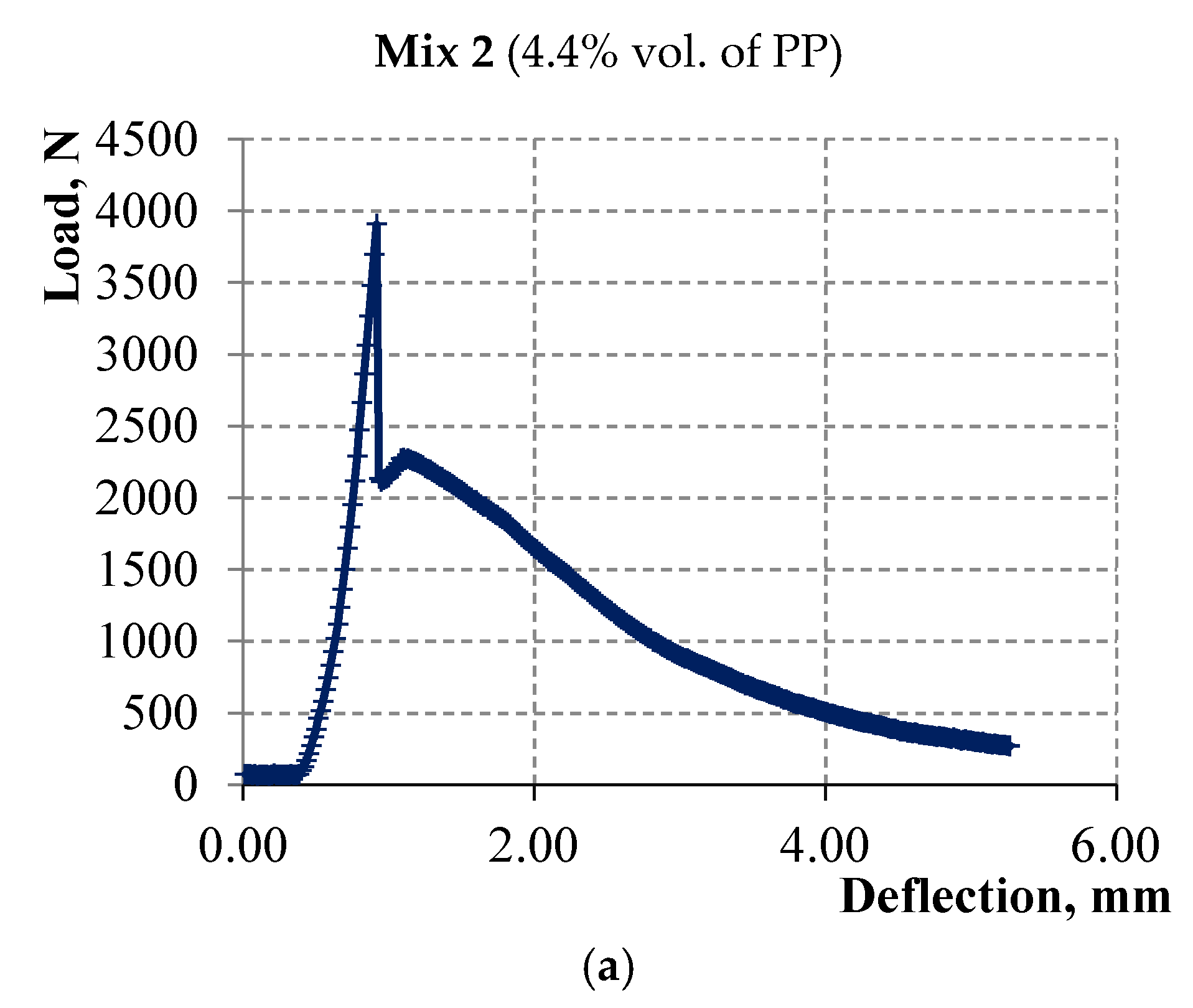
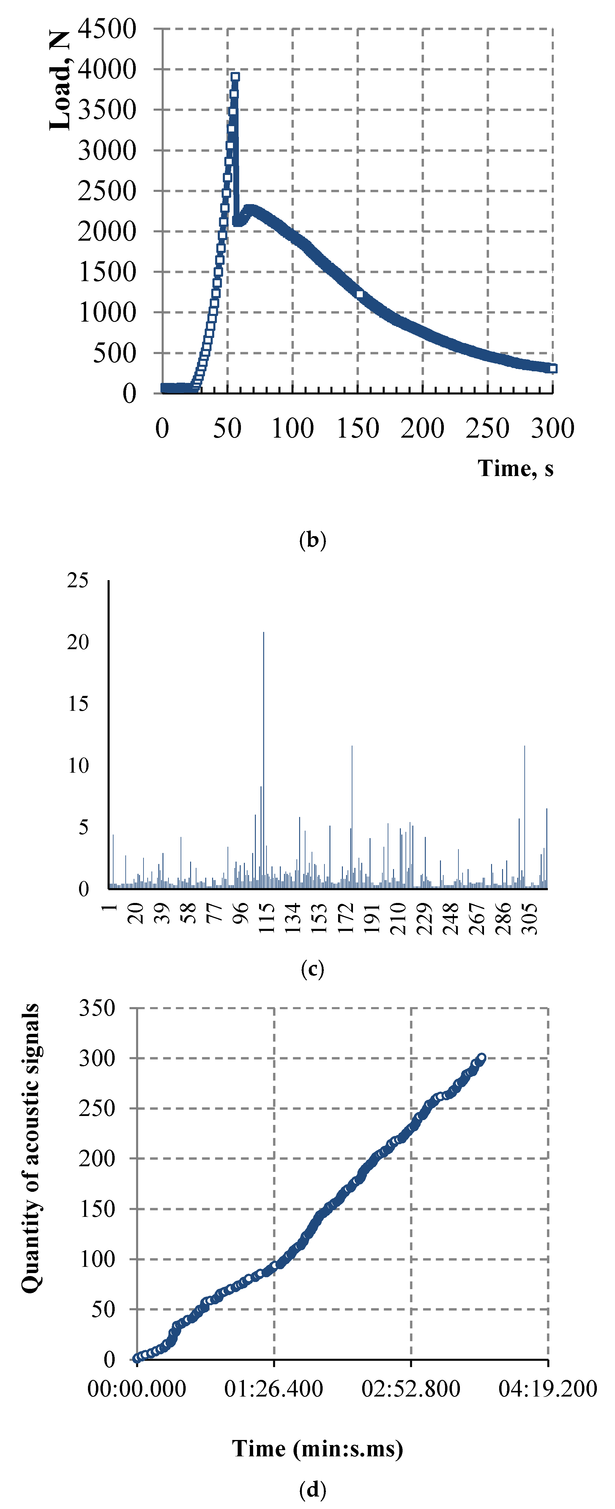
| PP microfiber % by vol. | 4.4% | 5.5% |
| Mix 3 | Mix 4 | |
|---|---|---|
| Ground granulated blast furnace slag | 1133 | 1275 |
| Ground quartz sand A4 | 224 | 232 |
| Quartz sand 0.06–2 mm | 113 | 120 |
| PP microfiber | 32 | 32 |
| Liquid glass with the density of 1.3 g/cm3 and with the silicate module equal to 1.5 | 120 | 122 |
| NaOH | 38 | 41 |
| Water | 338 | 280 |
| Water-to-slag ratio | 0.3 | 0.22 |
| Density after mixing, kg/m3 | 1998 | 2102 |
| Density at the age of 28 days, kg/m3 | 1961 | 2025 |
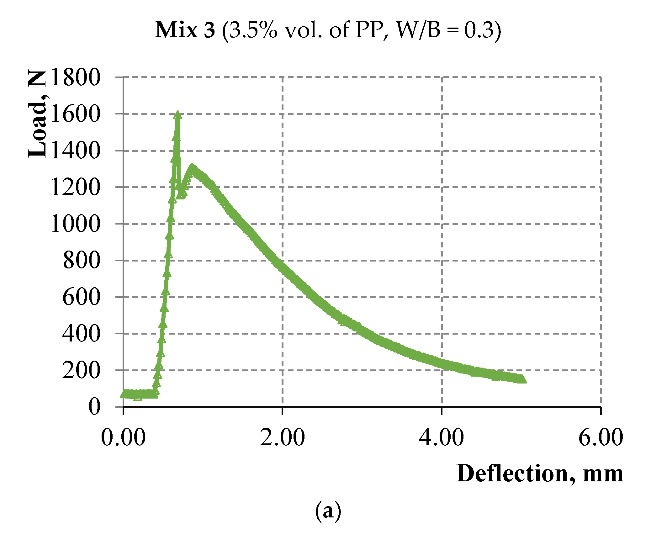
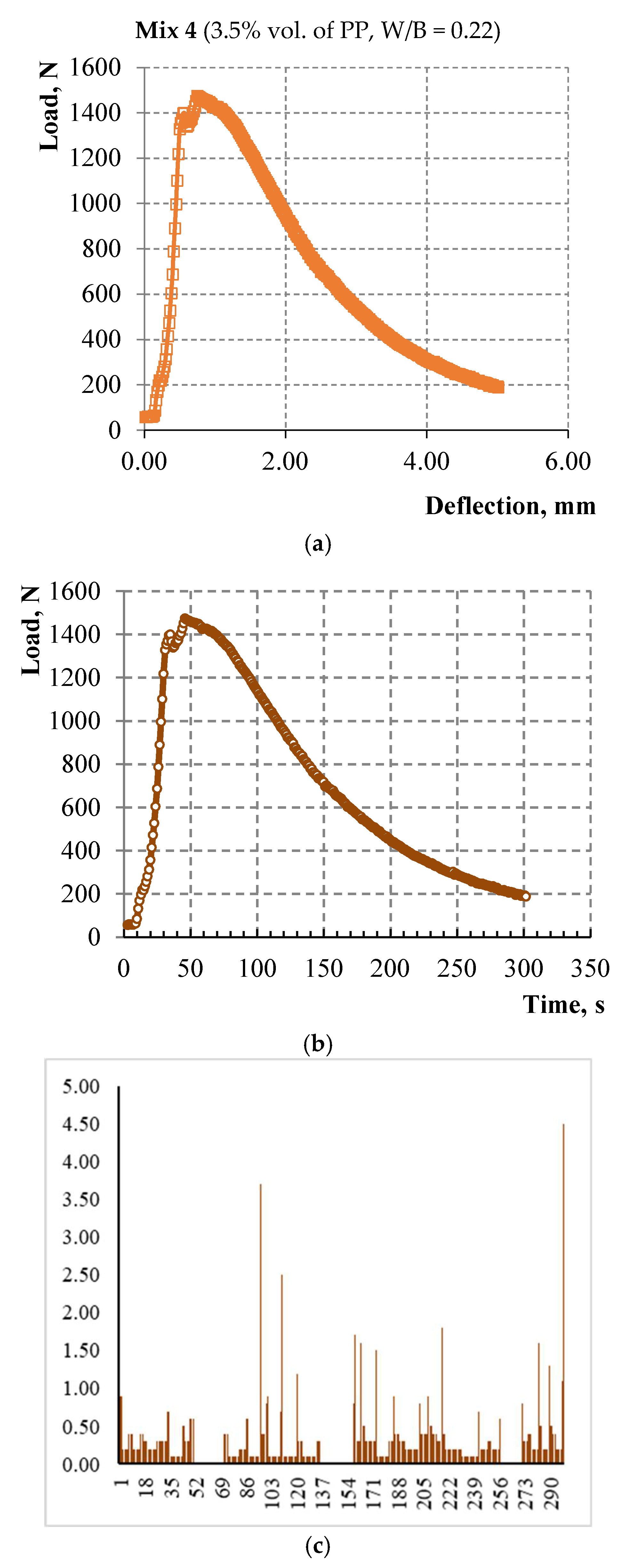
| PP microfiber % by vol. | 3.5% | 3.5% |
| Compressive Strength, MPa | Standard Deviation, MPa | Coefficient of Variation, % | Tensile Strength in Bending at First Microcrack, MPa | Standard Deviation, MPa | Coefficient of Variation, % | |
|---|---|---|---|---|---|---|
| Mix 2 (CEM) | 79.59 | 2.89 | 4.63 | 7.93 | 1.42 | 17.89 |
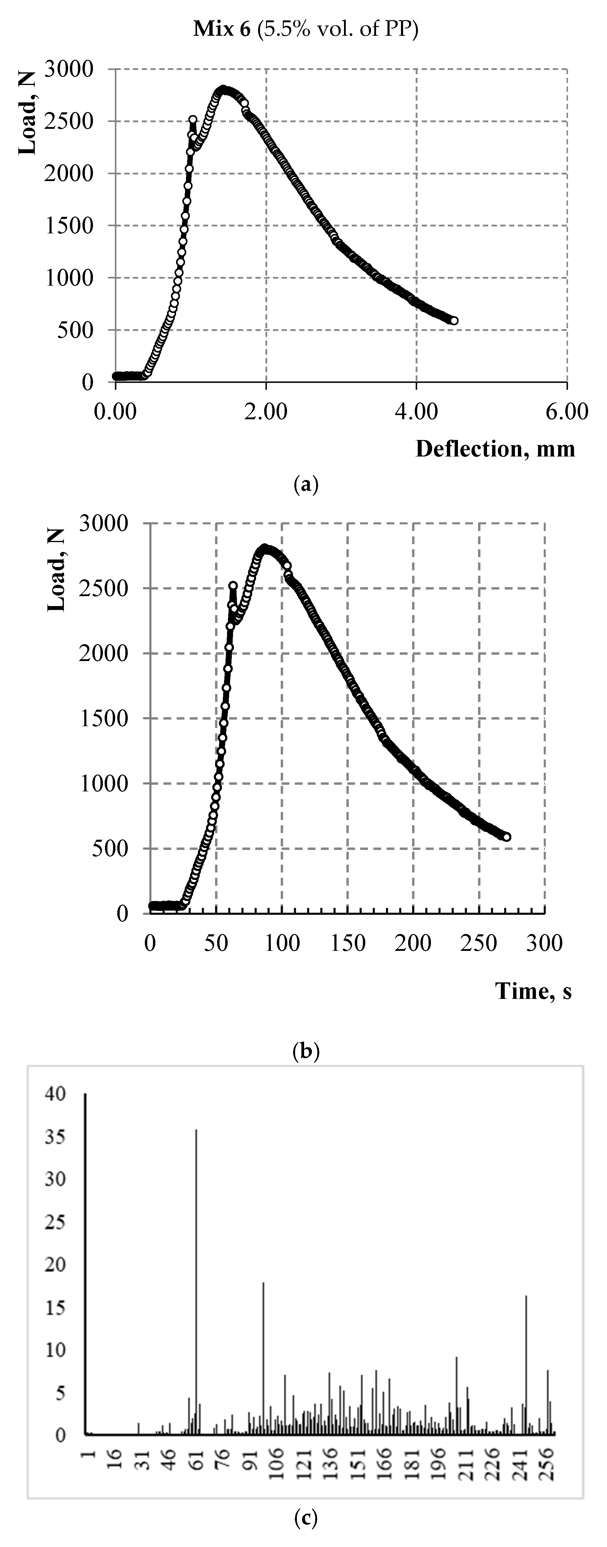
| Mix 6 (CEM) | 68.06 | 2.72 | 3.99 | 5.81 | 0.76 | 13.05 |
| Mix 3 (slag) | 42.37 | 2.86 | 4.52 | 3.85 | 0.56 | 14.57 |
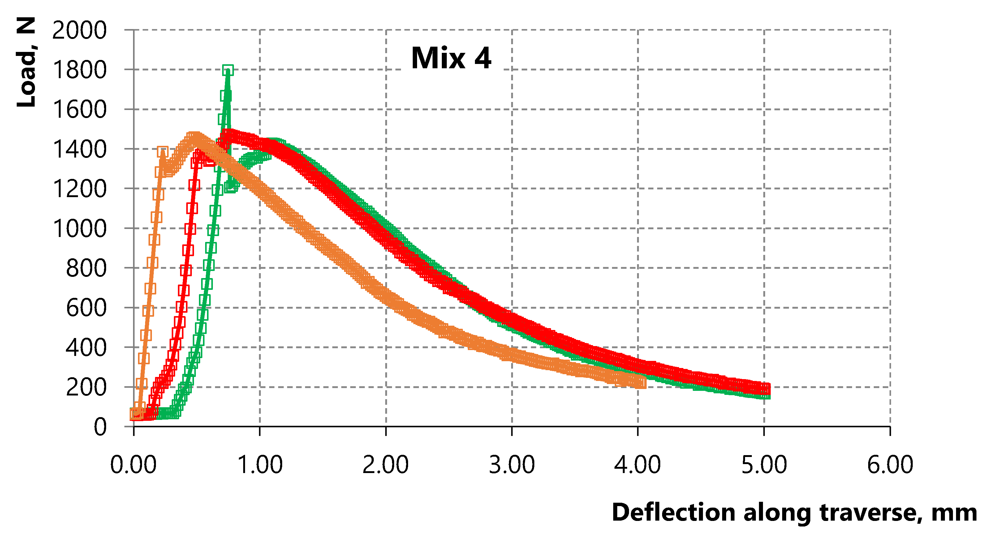
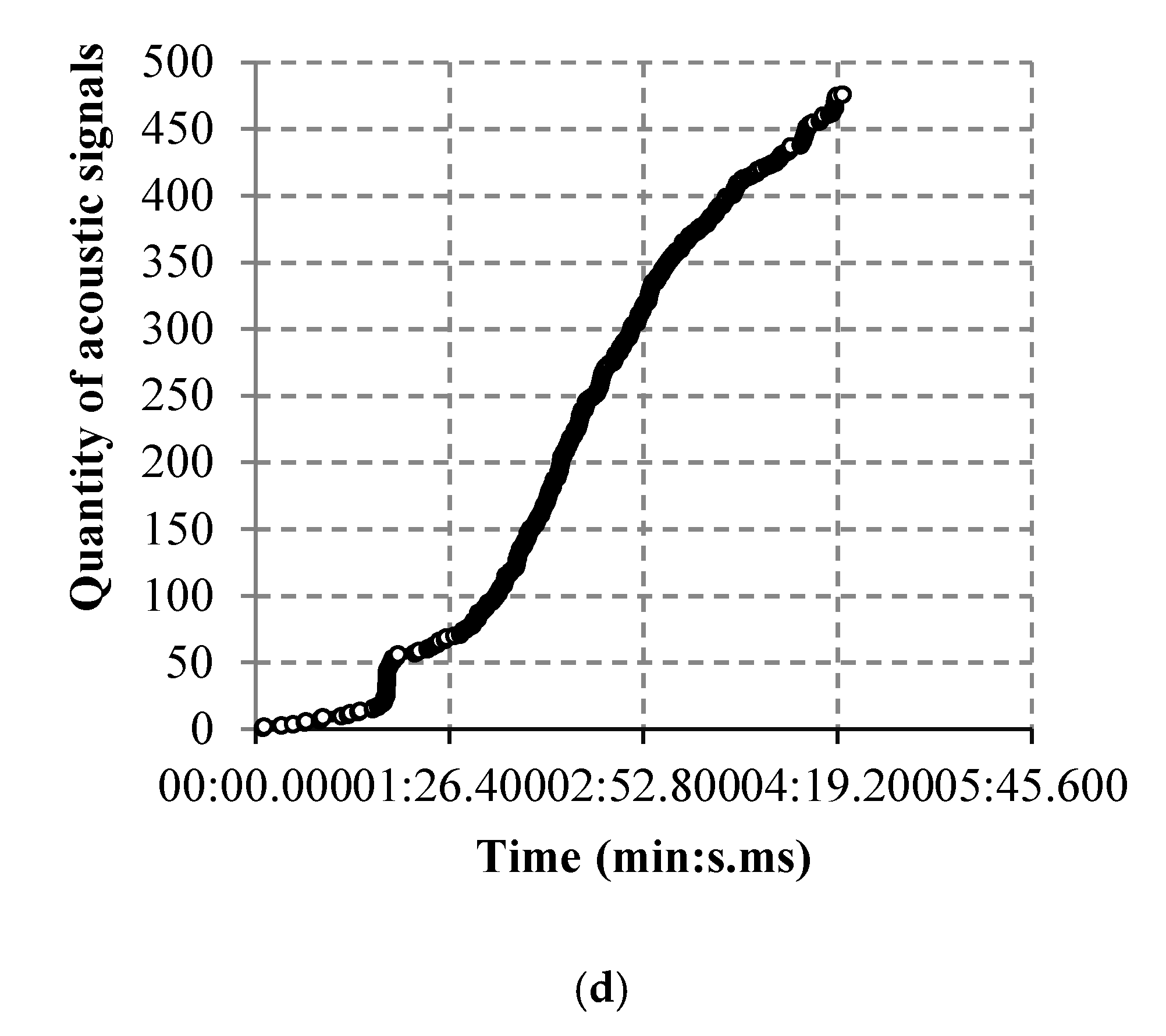
| Mix 4 (slag) | 39.86 | 2.91 | 4.21 | 3.45 | 0.30 | 8.60 |
| Composition. | Mix 2 | Mix 6 | Mix 3 | Mix 4 |
|---|---|---|---|---|
| Compressive strength, MPa | 79.59 | 68.06 | 42.37 | 39.86 |
| Tensile strength in bending, MPa (at the first microcrack) | 7.93 | 5.81 | 3.85 | 3.45 |
| Specific fracture work, J/m3 | 22,200.4 | 23,176.9 | 10,351.5 | 13,281.2 |
| Strain-hardening after the formation of the first microcrack, MPa | 0 | 0.64 | 0 | 0.23 |
| Deflection value, mm | 1.15 | 1.17 | 1.04 | 1.08 |
Publisher’s Note: MDPI stays neutral with regard to jurisdictional claims in published maps and institutional affiliations. |
© 2022 by the authors. Licensee MDPI, Basel, Switzerland. This article is an open access article distributed under the terms and conditions of the Creative Commons Attribution (CC BY) license (https://creativecommons.org/licenses/by/4.0/).
Share and Cite
Smirnova, O.M.; Menendez Pidal, I.; Alekseev, A.V.; Petrov, D.N.; Popov, M.G. Strain Hardening of Polypropylene Microfiber Reinforced Composite Based on Alkali-Activated Slag Matrix. Materials 2022, 15, 1607. https://doi.org/10.3390/ma15041607
Smirnova OM, Menendez Pidal I, Alekseev AV, Petrov DN, Popov MG. Strain Hardening of Polypropylene Microfiber Reinforced Composite Based on Alkali-Activated Slag Matrix. Materials. 2022; 15(4):1607. https://doi.org/10.3390/ma15041607
Chicago/Turabian StyleSmirnova, Olga M., Ignacio Menendez Pidal, Aleksandr V. Alekseev, Dmitry N. Petrov, and Mikhail G. Popov. 2022. "Strain Hardening of Polypropylene Microfiber Reinforced Composite Based on Alkali-Activated Slag Matrix" Materials 15, no. 4: 1607. https://doi.org/10.3390/ma15041607
APA StyleSmirnova, O. M., Menendez Pidal, I., Alekseev, A. V., Petrov, D. N., & Popov, M. G. (2022). Strain Hardening of Polypropylene Microfiber Reinforced Composite Based on Alkali-Activated Slag Matrix. Materials, 15(4), 1607. https://doi.org/10.3390/ma15041607