
The Effect of Steel Beam Elastic Restraint on the Critical Moment of Lateral Torsional Buckling


Abstract
:1. Introduction
- (i)
- Approximate formulas were derived for the LTB critical moment (Mcr,u) of steel beams with bisymmetrical cross section that are bilaterally fixed against bending (My) and elastically restrained against warping. The LTB critical moment represents the upper limit of the critical resistance in the elastic range.
- (ii)
- Approximate formulas were derived for Mcr, for any degree of elastic restraint against rotation about the section major axis, and against warping at the support nodes. That was done based on the indexes of fixity that are independent of one another.
- (iii)
- A solution was obtained that allows for a more accurate representation of the actual LTB behaviour of a steel beam using a relatively simple analytical model (cf. calculation example in Section 5.4).
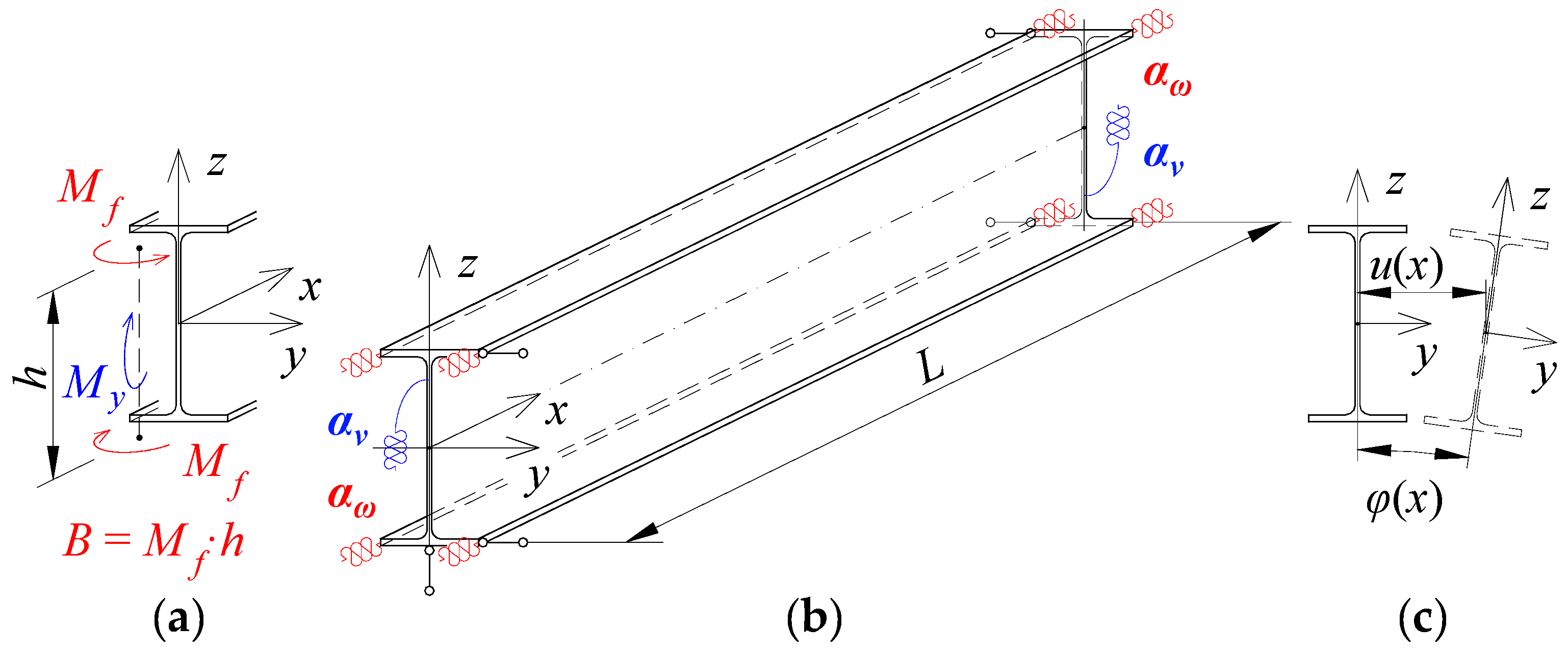
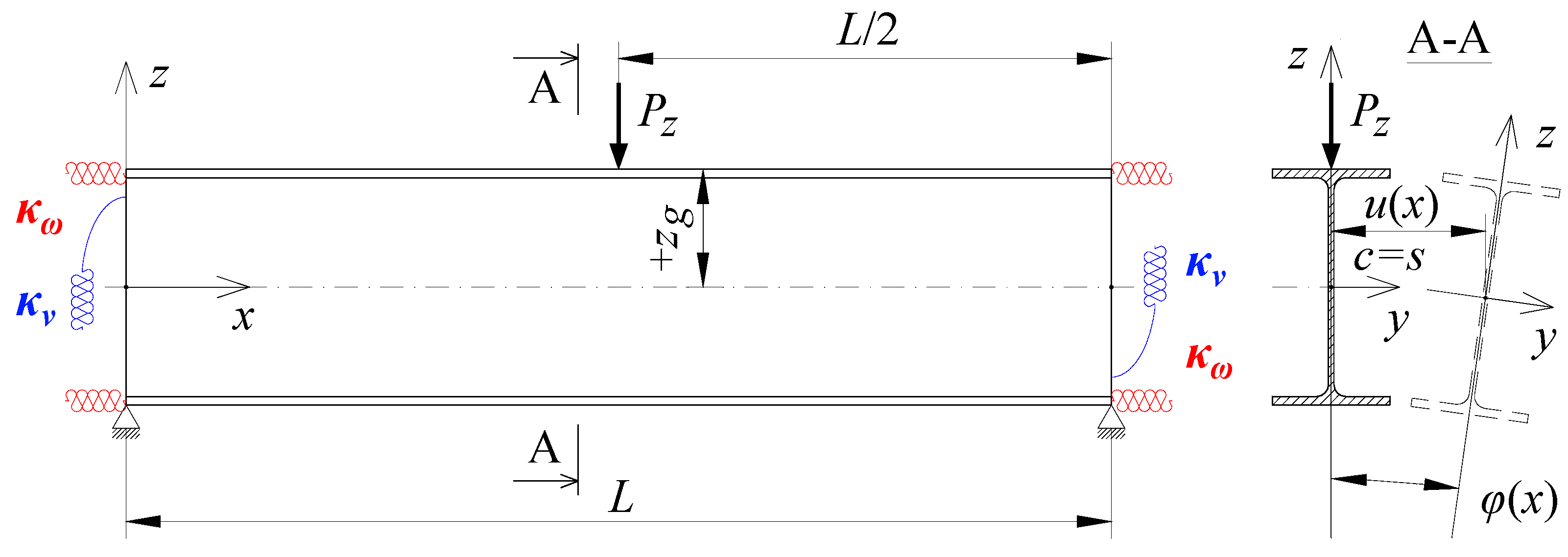
2. Beam Elastic Restraint against Warping and against Rotation in Its Bending Plane
3. LTB Critical Moment of a Fixed Beam
3.1. Function of the Twist Angle
3.2. Determination of Mcr,u with the Energy Method
3.3. Approximate Equation for Mcr,u in a Bilaterally Fixed Beam
4. Approximate Equations for the LTB Critical Moment in an Elastically Restrained Beam
- in the case of the load of (a) a force concentrated at the midspan, (b) uniformly distributed, or (c) distributed triangularly and applied to the top flange TF, the critical load (Pcr, qcr, qTcr) can be determined as a linear combination of a critical load for a simply supported (Po, qo, qTo) and fully fixed beam (Pu, qu, qTu) according to the equations:
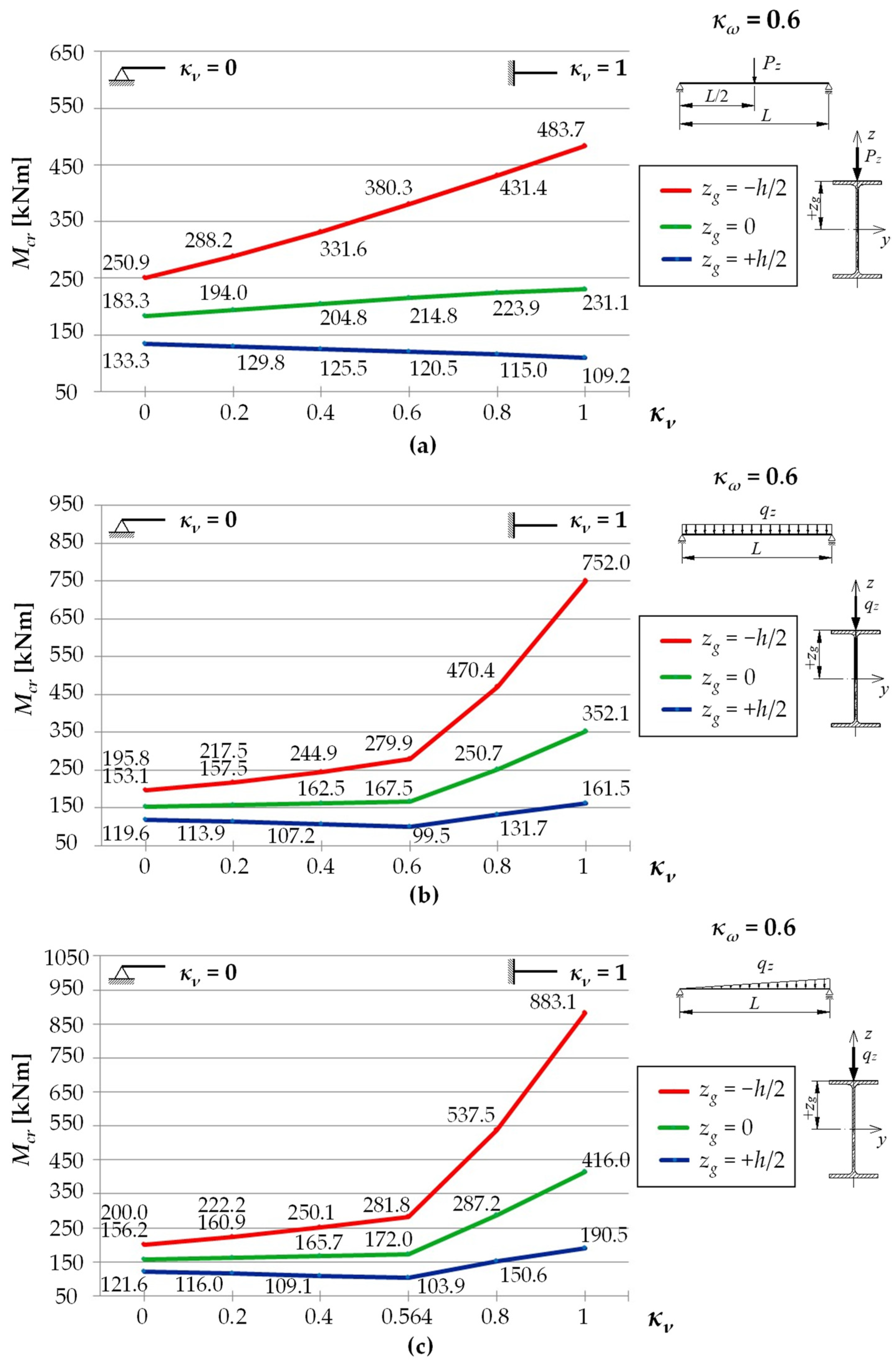
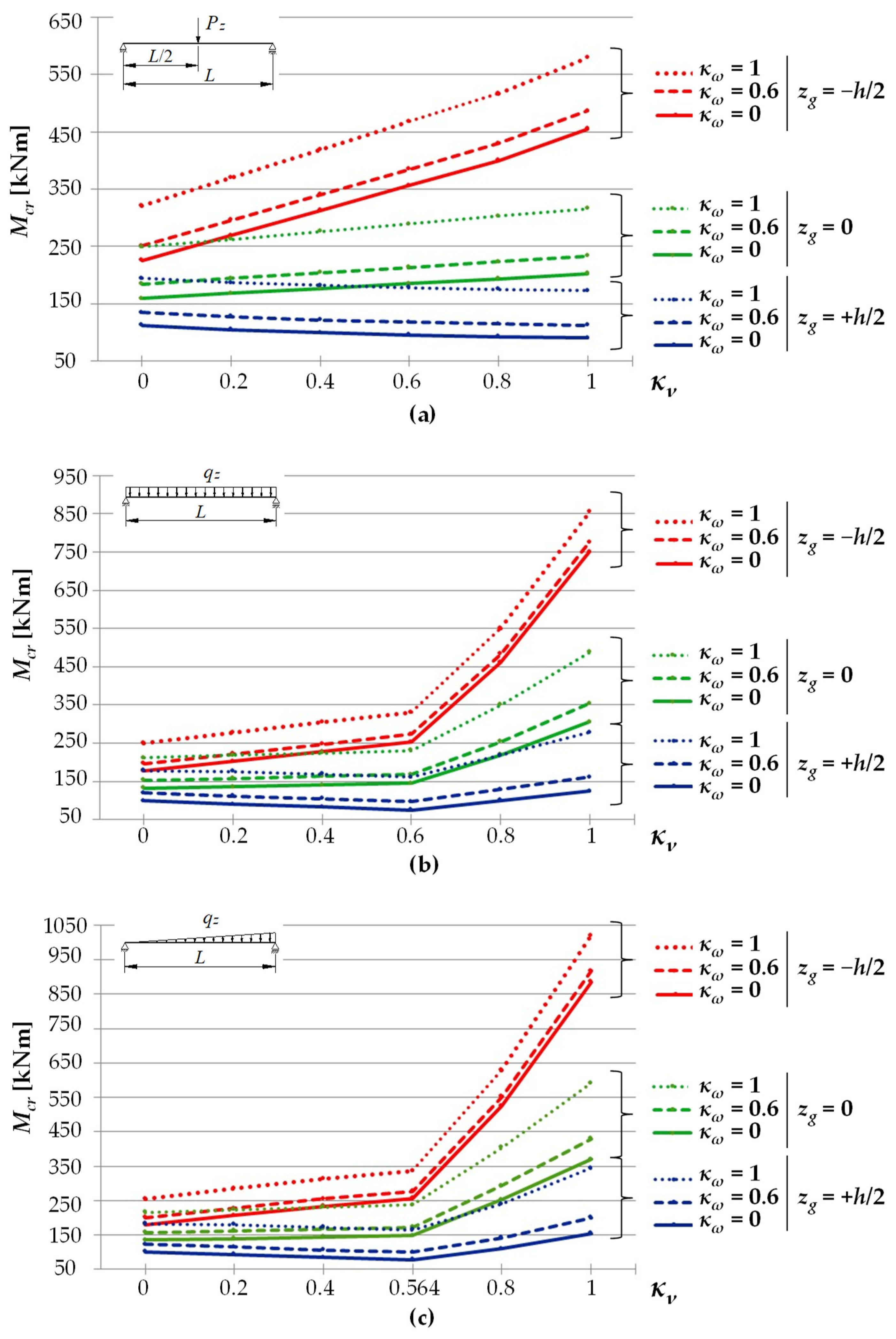
- in the case of a concentrated force load at the midspan, applied in the axis of gravity of the cross section CG, or applied to the bottom flange BF of the beam, the coefficient depends on the κν index in a linear manner (see Figure 3a) for various coefficients of proportionality (where: —a coefficient depending on the point of the load application, CG or BF);
- in the case of a load distributed uniformly or triangularly, and applied in the axis of gravity of the cross section CG, or applied to the bottom flange BF of the beam, the best results for the coefficient were obtained when assuming its linear variation as a function of the index in the form of (where: —coefficients depending on the point of load application).
- Load of a force concentrated at the midspan:
- 2.
- Uniformly distributed load:
- 3.
- Triangularly distributed load:
5. Verification of Approximate Equations by FEM
5.1. Assumptions
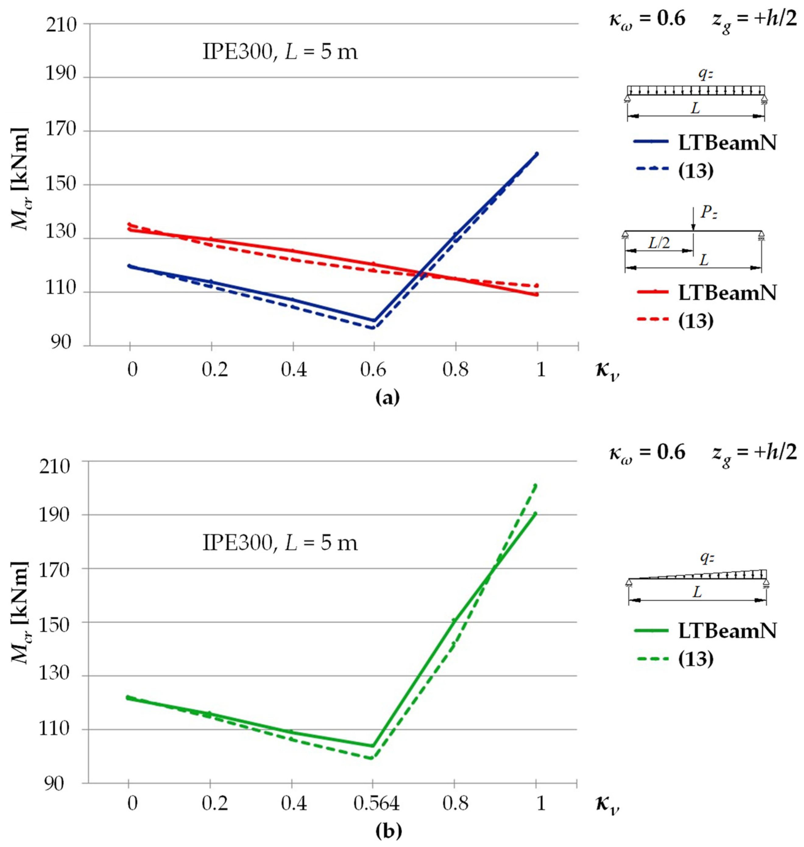
5.2. The Case of a Bilaterally Fixed Beam (κν = 1)
5.3. The Case of a Bilaterally Elastically Restrained Beam ()
5.4. Example of Calculations
- Calculation of elastic restraint indices of the beam: (a) against warping according to Equation (1): κω = 0.76; (b) against rotation in the bending plane according to Equation (3): κν = 0.82;
- The critical moment Mo of a beam simply supported against bending relative to the axis of higher rigidity (κν = 0), and elastically restrained against warping (κω = 0.76), was calculated from Equation (11) and Table 3 (row 2): Mo = 101.51 kNm;
- The critical moment Mu of a beam fully fixed against bending relative to the axis of higher rigidity (κν = 1), and elastically restrained against warping (κω = 0.76), was calculated from Equation (11) and Table 4 (row 2): Mu = 146.73 kNm;
- The coefficient of interaction η was calculated from Equation (18) for a range of 0.6 < κν < 1: η(κν = 0.82) = 0.395;
- The LTB critical moment for an elastically restrained beam for the indices: κω = 0.76 and κυ = 0.82 was calculated from Equation (13): Mcr = 101.51 + (146.73 – 101.51) ∗ 0.395 = 119.38 kNm.
6. Conclusions
Author Contributions
Funding
Institutional Review Board Statement
Informed Consent Statement
Conflicts of Interest
References
- Bijak, R. Critical Moment for Lateral Torsional Buckling of Unbraced Bisymmetric I-Beams with Fork Support. In Proceedings of the XII International Scientific and Technical Conference Metal Structures, Wrocław, Poland, 15–17 June 2011; pp. 144–151. (In Polish). [Google Scholar]
- Lim, N.H.; Park, N.H.; Kang, Y.J.; Sung, I.H. Elastic buckling of I-beams under linear moment gradient. Int. J. Solids Struct. 2003, 40, 5635–5647. [Google Scholar] [CrossRef]
- López, A.; Yong, D.J.; Serna, M.A. Lateral-torsional buckling of steel beams: A general expression for the moment gradient factor. In Proceedings of the International Colloquium on Stability and Ductility of Steel Structures, Lisbon, Portugal, 6–8 September 2006. [Google Scholar]
- Mohri, F.; Damil, N.; Potier-Ferry, M. Linear and non-linear stability analyses of thin-walled beams with monosymmetric I sections. Thin-Walled Struct. 2010, 48, 299–315. [Google Scholar] [CrossRef]
- Serna, M.A.; López, A.; Puente, I.; Yong, D.J. Equivalent uniform moment factors for lateral-torsional buckling of steel members. J. Constr. Steel Res. 2006, 62, 566–580. [Google Scholar] [CrossRef]
- Trahair, N.S.; Bradford, M.A.; Nethercot, D.A.; Gardner, L. The Behavior and Design of Steel Structures to EC3, 4th ed.; Taylor & Francis: London, UK, 2008. [Google Scholar]
- Bijak, R. The lateral buckling of simply supported unrestrained bisymmetric I-shape beams. Arch. Civ. Eng. 2015, 61, 127–140. [Google Scholar] [CrossRef]
- Mohri, F.; Brouki, A.; Roth, J.C. Theoretical and numerical stability analyses of unrestrained, mono symmetric thin-walled beams. J. Constr. Steel Res. 2003, 59, 63–90. [Google Scholar] [CrossRef]
- Timoshenko, S.P.; Gere, J.M. Theory of Elastic Stability, 2nd ed.; McGraw-Hill: New York, NY, USA, 1961. [Google Scholar]
- Weiss, S.; Giżejowski, M. Stability of Metal Structures. Rod Systems, 1st ed.; Arkady: Warszawa, Poland, 1991. (In Polish) [Google Scholar]
- Valentino, J.; Trahair, N.S. Torsional Restraint against Elastic Lateral Buckling. J. Struct. Eng. 1998, 124, 1217–1225. [Google Scholar] [CrossRef]
- Yura, J. Fundamentals of beam bracing. Eng. J. 2001, 38, 11–26. [Google Scholar]
- Gosowski, B. Non-uniform torsion of stiffened open thin-walled members of steel structures. J. Constr. Steel Res. 2007, 63, 849–865. [Google Scholar] [CrossRef]
- Gosowski, B.; Redecki, M. Lateral-torsional buckling moments for I-beams with local lateral restraints. Inż. Bud. 2012, 68, 140–144. (In Polish) [Google Scholar]
- Lee, H.E.; Nguyen, C.T.; Moon, J.H.; Joo, H.S. Lateral-torsional buckling of discretely-braced i-girder. Procedia Eng. 2011, 14, 264–271. [Google Scholar] [CrossRef] [Green Version]
- Stroetmann, R. Lateral torsional and distortional buckling of cross-connected beams. In Proceedings of the 8th International Conference on Advances in Steel Structures, Lisbon, Portugal, 21–24 July 2015. [Google Scholar]
- Piotrowski, R.; Siedlecka, M. Point Protection of Primary Beams of Steel Grillages Against Lateral Torsional Buckling. Adv. Sci. Technol. Res. J. 2020, 14, 1–8. [Google Scholar] [CrossRef]
- Nguyen, C.T.; Moon, J.; Le, V.N.; Lee, H.E. Lateral–torsional buckling of I-girders with discrete torsional bracings. J. Constr. Steel Res. 2010, 66, 170–177. [Google Scholar] [CrossRef]
- Beyer, A.; Bureau, A. Simplified method for lateral-torsional buckling of beams with lateral restraints. Steel Constr. 2019, 12, 318–326. [Google Scholar] [CrossRef]
- Lindner, J. Influence of constructional details on the load carrying capacity of beams. Eng. Struct. 1996, 18, 752–758. [Google Scholar] [CrossRef]
- Bijak, R.; Brzezińska, K. Reduction in the Critical Moment for Lateral Torsional Buckling of Coped Beams. Appl. Mech. Mater. 2015, 797, 3–10. [Google Scholar] [CrossRef]
- Maljaars, J.; Stark, J.W.B.; Steenbergen, H.M.G.M. Buckling of coped steel beams and steel beams with partial endplates. HERON 2004, 49, 233–271. [Google Scholar]
- Giżejowski, M. Lateral buckling of steel beams with limited rotation ability at supports. Inż. Bud. 2001, 10, 589–594. (In Polish) [Google Scholar]
- Johnston, G.; Driver, R.G.; Callele, L. Behaviour and Stability of Double-coped Beam-to-girder Connections under Combined Loading. In Proceedings of the Annual Stability Conference, Structural Stability Research Council, Toronto, ON, Canada, 25–28 March 2014. [Google Scholar]
- Maljaars, J.; Stark, J.W.B.; Steenbergen, H.M.G.M.; Abspoel, R. Lateral–torsional buckling resistance of coped beams. J. Constr. Steel Res. 2005, 61, 1559–1575. [Google Scholar] [CrossRef]
- Maljaars, J.; Stark, J.W.B.; Steenbergen, H.M.G.M.; Abspoel, R. Development and validation of a numerical model for buckling of coped beams. J. Constr. Steel Res. 2005, 61, 1576–1593. [Google Scholar] [CrossRef]
- Lam, C.C.; Yam, M.C.H.; Iu, V.P.; Cheng, J.J.R. Design for lateral torsional buckling of coped I-beams. J. Constr. Steel Res. 2000, 54, 423–443. [Google Scholar] [CrossRef]
- Barszcz, A.M.; Giżejowski, M.A.; Stachura, Z. On Elastic Lateral-Torsional Buckling Analysis of Simply Supported I-Shape Beams Using Timoshenko’s Energy Method. In Modern Trends in Research on Steel, Aluminium and Composite Structures, 1st ed.; Giżejowski, M.A., Kozłowski, A., Chybiński, M., Rzeszut, K., Studziński, R., Szumigała, M., Eds.; Taylor & Francis: London, UK, 2021; pp. 92–98. [Google Scholar] [CrossRef]
- Mohri, F.; Bouzerira, C.; Potier-Ferry, M. Lateral buckling of thin-walled beam-column elements under combined axial and bending loads. Thin-Walled Struct. 2008, 46, 290–302. [Google Scholar] [CrossRef]
- Mohri, F.; Damil, N.; Potier-Ferry, M. Buckling and lateral buckling interaction in thin-walled beam-column elements with mono-symmetric cross sections. Appl. Math. Model. 2013, 37, 3526–3540. [Google Scholar] [CrossRef]
- Giżejowski, M.; Barszcz, A.M.; Stachura, Z. Elastic Flexural-Torsional Buckling of Steel I-Section Members Unrestrained between End Supports. Arch. Civ. Eng. 2021, 67, 635–656. [Google Scholar] [CrossRef]
- Giżejowski, M.; Kozłowski, A.; Stachura, Z. Experimental investigations of the flexural-torsional buckling resistance: Steel rolled I-section beam-columns under moment gradient. Ce/Pap. Online Collect. Conf. Pap. Civ. Eng. 2021, 4, 2115–2123. [Google Scholar] [CrossRef]
- Piotrowski, R.; Szychowski, A. Impact of support closed section ribs on the critical moment for lateral torsional buckling of steel beams. Struct. Environ. 2018, 10, 5–18. [Google Scholar] [CrossRef]
- Lindner, L.; Gietzelt, R. Stabilisierung von Biegeträgern mit I-Profil durch angeschweiβte Kopfplatten. Stahlbau 1984, 3, 69–74. [Google Scholar]
- Gotluru, B.P.; Schafer, B.W.; Pekoz, T. Torsion in thin-walled cold-formed steel beams. Thin-Walled Struct. 2000, 37, 127–145. [Google Scholar] [CrossRef]
- Kurzawa, Z.; Rzeszut, K.; Szumigała, M.; Chybiński, M. The influence of frontal plates on the load-carrying capacity of beams in bending. Inż. Bud. 2006, 62, 163–166. (In Polish) [Google Scholar]
- Pi, Y.-L.; Trahair, N.S. Distortion and warping at beam supports. J. Struct. Eng. 2000, 126, 1279–1287. [Google Scholar] [CrossRef]
- Wierzbicki, K. Influence of Bimoment Restraints on the Load-Bearing Capacity of a Steel I-Beam. Civ. Environ. Eng. Rep. 2020, 30, 33–47. [Google Scholar] [CrossRef]
- Bijak, R.; Kowal, Z.; Malec, M. Critical Load Capacity of Continuous Beams Stiffened with Closed Section Ribs. Current Research and Development Problems in Construction; Metal and Wooden Constructions: Krynica, Poland, 1988; pp. 17–22. (In Polish) [Google Scholar]
- Březina, V. The Stability of Bars in Steel Structures; Arkady: Warszawa, Poland, 1966. (In Polish) [Google Scholar]
- Gergovich, K. The Analysis of Stability of Steel Complex Rods. Current Research and Development Problems in Construction; Metal and Wooden Constructions: Krynica, Poland, 1988; pp. 41–46. (In Polish) [Google Scholar]
- Gosowski, B. Research for Lateral Torsional Buckling of I-Section Steel Beams with Closed Section Ribs. Current Research and Development Problems in Construction; Metal and Wooden Constructions: Krynica, Poland, 1988; pp. 47–52. (In Polish) [Google Scholar]
- Kowal, Z.; Malec, M. Critical resistance of beams with support ribs with closed section. Inż. Bud. 1989, 2, 71–74. (In Polish) [Google Scholar]
- Pałkowski, S. Lateral torsional buckling of I-beams with end plates. Inż. Bud. 1997, 8, 394–395. (In Polish) [Google Scholar]
- Masarira, A. The effect of joints on the stability behaviour of steel frame beams. J. Constr. Steel Res. 2002, 58, 1375–1390. [Google Scholar] [CrossRef]
- Živner, T.J. The Influence of Constructional Detail to Lateral-Torsional Buckling of Beams. Procedia Eng. 2012, 40, 504–509. [Google Scholar] [CrossRef] [Green Version]
- Trinh, D.K.; Nguyen, M.T.; Bui, H.C. Effects of End-Plate on the Critical Moment of I-Section Cantilever Beam with Free End Restrained Laterally. J. Sci. Technol. Civ. Eng. 2021, 15, 102–109. [Google Scholar] [CrossRef]
- Kuś, J.; Maleska, T. Lateral Torsional Buckling of Tapered Steel I-Beams with Stiffener Ribs. In Modern Trends in Research on Steel, Aluminium and Composite Structures, 1st ed.; Giżejowski, M.A., Kozłowski, A., Chybiński, M., Rzeszut, K., Studziński, R., Szumigała, M., Eds.; Taylor & Francis: London, UK, 2021; pp. 428–434. [Google Scholar] [CrossRef]
- Lebastard, M.; Couchaux, M.; Bureau, A.; Hjiaj, M. Lateral-Torsional Buckling of beams with warping restraints at Supports. Ce/Pap. Online Collect. Conf. Pap. Civ. Eng. 2021, 4, 2262–2270. [Google Scholar] [CrossRef]
- Piotrowski, R.; Szychowski, A. Lateral Torsional Buckling of Steel Beams Elastically Restrained at the Support Nodes. Appl. Sci. 2019, 9, 1944. [Google Scholar] [CrossRef] [Green Version]
- Vlasov, V.Z. Thin-Walled Elastic Beams, 2nd ed.; Israel Program for Scientific Translations: Jerusalem, Israel, 1961. [Google Scholar]
- Piotrowski, R.; Szychowski, A. Lateral-torsional buckling of beams elastically restrained against warping at supports. Arch. Civ. Eng. 2015, 61, 155–174. [Google Scholar] [CrossRef] [Green Version]
- EN 1993-1-1 Eurocode 3: Design of Steel Structures—Part 1-1: General Rules and Rules for Buildings. In The European Union: Edict of Government; CEN: Brussels, Belgium, 2005.
- EN 1993-1-3 Eurocode 3: Design of Steel Structures—Part 1-3: General Rules—Supplementary Rules for Cold-Formed Members and Sheeting. In The European Union: Edict of Government; CEN: Brussels, Belgium, 2006.
- EN 1993-1-5 Eurocode 3: Design of Steel Structures—Part 1-5: General Rules—Plated Structural Elements. In The European Union: Edict of Government; CEN: Brussels, Belgium, 2006.
- Argyridi, A.; Sapountzakis, E. Generalized Warping in Flexural-Torsional Buckling Analysis of Composite Beams. J. Appl. Comput. Mech. 2016, 2, 152–173. [Google Scholar] [CrossRef]
- Giżejowski, M.; Bródka, J. Frame structures with semi-rigid joints-stability problems. In Proceedings of the Research of the Ultimate Load Capacity of Metal Strutures, Szklarska Poręba, Poland, 23–25 October 1998; Biegus, A., Ed.; OWPWr: Wrocław, Poland, 1998; pp. 159–168. (In Polish). [Google Scholar]
- European Prestandard ENV 1993-1-1:1992 Eurocode 3: Design of Steel Structures. Part 1.1: General Rules and Rules for Buildings; European Committee for Standardization: Brussels, Belgium, 1992.
- Gardner, L.; Fieber, A.; Macorini, L. Formulae for calculating elastic local buckling stresses of full structural cross-sections. Structures 2019, 17, 2–20. [Google Scholar] [CrossRef]
- Piotrowski, R.; Szychowski, A. Applying the Energy Method and Polynomials to the Determination of the Critical Buckling Moments in Beams. In Concrete and Metal Structures, 1st ed.; Flizikowski, J., Piotrowska, E., Podhorecki, A., Eds.; WUUT-P: Bydgoszcz, Poland, 2015; pp. 249–257. (In Polish) [Google Scholar]
- Jakubowski, S. Buckling of thin-walled girders under compound load. Thin-Walled Struct. 1988, 6, 129–150. [Google Scholar] [CrossRef]
- Szychowski, A. A theoretical analysis of the local buckling in thin-walled bars with open cross-section subjected to warping torsion. Thin-Walled Struct. 2014, 76, 42–55. [Google Scholar] [CrossRef]
- Galéa, Y. Moment critique de déversement élastique de poutres fléchies. Présentation du logiciel LTBEAM. Rev. Constr. Mét. CTICM 2003, 40, 47–76. [Google Scholar]

| Item | Polynomials | Physical Interpretation |
|---|---|---|
| I | II | III |
| 1 |  | |
| 2 | 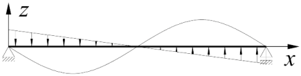 | |
| 3 | 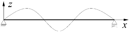 | |
| 4 |  | |
| 5 | 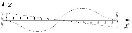 | |
| 6 | 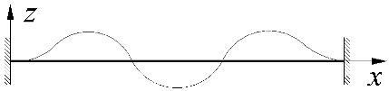 |
| Item | Static Scheme | The Work of External Forces |
|---|---|---|
| I | II | III |
| 1 | 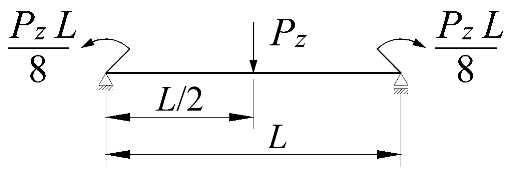 | |
| 2 | 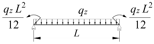 | |
| 3 | 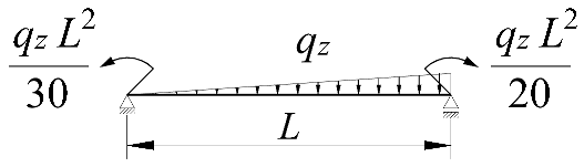 |
| Item | Static Scheme | Coefficients |
|---|---|---|
| I | II | III |
| 1 | 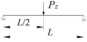 | |
| 2 |  | |
| 3 |  |
| Item | Static Scheme | Coefficients |
|---|---|---|
| I | II | III |
| 1 |  | |
| 2 |  | |
| 3 |  |
| Item | Static Scheme | κω | zg | Mcr [kNm] | ||||
|---|---|---|---|---|---|---|---|---|
| LTBeam | MLTB,EL,u | % VI–V | Equation (11) | % VIII–V | ||||
| I | II | III | IV | V | VI | VII | VIII | IX |
| 1 | 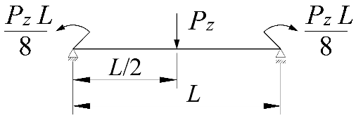 | 0 | +h/2 | 87.7 | 88.4 | 0.7 | 90.2 | 2.8 |
| 2 | 0 | 201.0 | 201.3 | 0.2 | 202.6 | 0.8 | ||
| 3 | −h/2 | 451.2 | 453.3 | 0.5 | 454.9 | 0.8 | ||
| 4 | 0.25 | +h/2 | 93.8 | 94.5 | 0.8 | 96.5 | 2.9 | |
| 5 | 0 | 209.7 | 210.1 | 0.2 | 211.5 | 0.9 | ||
| 6 | −h/2 | 459.8 | 461.9 | 0.4 | 463.6 | 0.8 | ||
| 7 | 0.5 | +h/2 | 103.4 | 104.3 | 0.8 | 106.5 | 2.9 | |
| 8 | 0 | 223.4 | 223.8 | 0.2 | 225.5 | 1.0 | ||
| 9 | −h/2 | 473.8 | 475.8 | 0.4 | 477.8 | 0.8 | ||
| 10 | 0.75 | +h/2 | 121.4 | 122.5 | 0.9 | 125.1 | 3.0 | |
| 11 | 0 | 248.4 | 249.0 | 0.2 | 251.3 | 1.2 | ||
| 12 | −h/2 | 499.9 | 501.8 | 0.4 | 504.9 | 1.0 | ||
| 13 | 0.9 | +h/2 | 142.4 | 143.8 | 1.0 | 146.9 | 3.1 | |
| 14 | 0 | 276.8 | 277.5 | 0.3 | 281.1 | 1.6 | ||
| 15 | −h/2 | 530.4 | 532.3 | 0.4 | 538.0 | 1.4 | ||
| 16 | 1 | +h/2 | 167.4 | 169.3 | 1.2 | 172.8 | 3.2 | |
| 17 | 0 | 309.6 | 310.7 | 0.3 | 316.4 | 2.2 | ||
| 18 | −h/2 | 566.2 | 567.9 | 0.3 | 579.6 | 2.4 | ||
| 19 |  | 0 | +h/2 | 124.4 | 124.4 | 0 | 124.2 | −0.1 |
| 20 | 0 | 304.3 | 304.4 | 0 | 305.3 | 0.3 | ||
| 21 | −h/2 | 727.9 | 732.8 | 0.7 | 750.3 | 3.1 | ||
| 22 | 0.25 | +h/2 | 134.6 | 134.6 | 0 | 134.4 | −0.1 | |
| 23 | 0 | 317.9 | 318.0 | 0 | 319.1 | 0.4 | ||
| 24 | −h/2 | 734.8 | 739.4 | 0.6 | 757.3 | 3.1 | ||
| 25 | 0.5 | +h/2 | 151.3 | 151.3 | 0 | 151.3 | 0 | |
| 26 | 0 | 339.4 | 339.6 | 0 | 341.1 | 0.5 | ||
| 27 | −h/2 | 745.9 | 750.1 | 0.6 | 768.8 | 3.1 | ||
| 28 | 0.75 | +h/2 | 183.9 | 183.9 | 0 | 184.3 | 0.2 | |
| 29 | 0 | 379.1 | 379.3 | 0.1 | 381.9 | 0.7 | ||
| 30 | −h/2 | 767.2 | 770.9 | 0.5 | 791.4 | 3.1 | ||
| 31 | 0.9 | +h/2 | 224.1 | 224.1 | 0 | 225.4 | 0.6 | |
| 32 | 0 | 424.6 | 425.0 | 0.1 | 429.8 | 1.2 | ||
| 33 | −h/2 | 792.8 | 796.3 | 0.4 | 819.5 | 3.4 | ||
| 34 | 1 | +h/2 | 274.3 | 274.3 | 0 | 278.3 | 1.5 | |
| 35 | 0 | 478.1 | 478.6 | 0.1 | 488.1 | 2.1 | ||
| 36 | −h/2 | 823.9 | 827.6 | 0.5 | 856.1 | 3.9 | ||
| 37 | 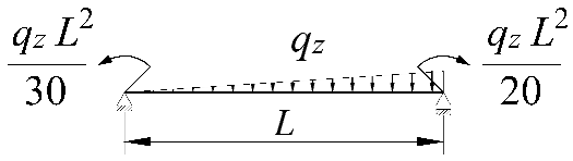 | +h/2 | 147.2 | 148.7 | 1.0 | 154.7 | 5.1 | |
| 38 | 0 | 0 | 359.7 | 359.9 | 0.1 | 370.1 | 2.9 | |
| 39 | −h/2 | 848.9 | 851.6 | 0.3 | 885.6 | 4.3 | ||
| 40 | +h/2 | 159.2 | 160.8 | 1.0 | 167.3 | 5.1 | ||
| 41 | 0.25 | 0 | 375.9 | 376.1 | 0.1 | 386.9 | 2.9 | |
| 42 | −h/2 | 858.1 | 859.9 | 0.2 | 894.5 | 4.2 | ||
| 43 | +h/2 | 179.0 | 180.8 | 1.0 | 188.1 | 5.1 | ||
| 44 | 0.5 | 0 | 401.4 | 401.7 | 0.1 | 413.5 | 3.0 | |
| 45 | −h/2 | 872.8 | 873.4 | 0.1 | 909.1 | 4.2 | ||
| 46 | +h/2 | 217.5 | 219.6 | 1.0 | 228.7 | 5.2 | ||
| 47 | 0.75 | 0 | 448.4 | 448.8 | 0.1 | 463.0 | 3.3 | |
| 48 | −h/2 | 900.6 | 899.5 | −0.1 | 937.4 | 4.1 | ||
| 49 | +h/2 | 265.0 | 267.4 | 0.9 | 279.2 | 5.3 | ||
| 50 | 0.9 | 0 | 502.5 | 503.0 | 0.1 | 521.1 | 3.7 | |
| 51 | −h/2 | 933.3 | 931.3 | −0.2 | 972.7 | 4.2 | ||
| 52 | +h/2 | 324.9 | 327.3 | 0.7 | 343.9 | 5.8 | ||
| 53 | 1 | 0 | 566.1 | 566.8 | 0.1 | 591.8 | 4.6 | |
| 54 | −h/2 | 972.5 | 970.3 | −0.2 | 1018.5 | 4.7 | ||
| Item | Static Scheme | κω | κν | Mcr [kNm] | ||
|---|---|---|---|---|---|---|
| LTBeamN | Equation (13) | % VI–V | ||||
| I | II | III | IV | V | VI | VII |
| 1 | 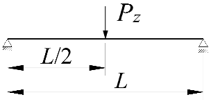 IPE300, L = 5m zg = +h/2 | 0 | 0 | 111.19 | 112.77 | 1.4 |
| 2 | 0.2 | 107.55 | 105.25 | −2.1 | ||
| 3 | 0.4 | 103.13 | 99.89 | −3.1 | ||
| 4 | 0.6 | 98.30 | 95.86 | −2.5 | ||
| 5 | 0.8 | 93.08 | 92.73 | −0.4 | ||
| 6 | 1 | 87.76 | 90.23 | 2.8 | ||
| 7 | 0.2 | 0 | 116.00 | 117.64 | 1.4 | |
| 8 | 0.2 | 112.35 | 110.09 | −2.0 | ||
| 9 | 0.4 | 108.00 | 104.70 | −3.1 | ||
| 10 | 0.6 | 103.12 | 100.66 | −2.4 | ||
| 11 | 0.8 | 97.82 | 97.51 | −0.3 | ||
| 12 | 1 | 92.38 | 95.00 | 2.8 | ||
| 13 | 0.4 | 0 | 122.82 | 124.54 | 1.4 | |
| 14 | 0.2 | 119.26 | 116.97 | −1.9 | ||
| 15 | 0.4 | 114.93 | 111.56 | −2.9 | ||
| 16 | 0.6 | 109.94 | 107.50 | −2.2 | ||
| 17 | 0.8 | 104.58 | 104.35 | −0.2 | ||
| 18 | 1 | 98.94 | 101.82 | 2.9 | ||
| 19 | 0.6 | 0 | 133.27 | 135.12 | 1.4 | |
| 20 | 0.2 | 129.78 | 127.54 | −1.7 | ||
| 21 | 0.4 | 125.50 | 122.13 | −2.7 | ||
| 22 | 0.6 | 120.52 | 118.07 | −2.0 | ||
| 23 | 0.8 | 115.02 | 114.91 | −0.1 | ||
| 24 | 1 | 109.21 | 112.39 | 2.9 | ||
| 25 | 0.8 | 0 | 151.47 | 153.50 | 1.3 | |
| 26 | 0.2 | 148.14 | 145.99 | −1.4 | ||
| 27 | 0.4 | 143.90 | 140.64 | −2.3 | ||
| 28 | 0.6 | 138.87 | 136.62 | −1.6 | ||
| 29 | 0.8 | 133.08 | 133.49 | 0.3 | ||
| 30 | 1 | 127.12 | 130.99 | 3.0 | ||
| 31 | 1 | 0 | 191.80 | 194.13 | 1.2 | |
| 32 | 0.2 | 188.74 | 187.01 | −0.9 | ||
| 33 | 0.4 | 184.64 | 181.92 | −1.5 | ||
| 34 | 0.6 | 179.58 | 178.10 | −0.8 | ||
| 35 | 0.8 | 173.80 | 175.13 | 0.8 | ||
| 36 | 1 | 167.43 | 172.76 | 3.2 | ||
| Item | Static Scheme | κω | κν | Mcr [kNm] | ||
|---|---|---|---|---|---|---|
| LTBeamN | Equation (13) | % VI–V | ||||
| I | II | III | IV | V | VI | VII |
| 1 | 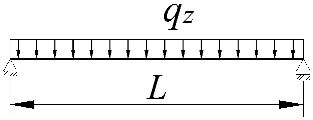 IPE300, L = 5m zg = +h/2 | 1 | 0 | 177.22 | 178.46 | 0.7 |
| 2 | 0.8 | 0.2 | 131.54 | 131.04 | −0.4 | |
| 3 | 0.6 | 0.4 | 107.24 | 104.49 | −2.6 | |
| 4 | 0.4 | 0.6 | 89.63 | 86.49 | −3.5 | |
| 5 | 0.2 | 0.8 | 109.05 | 106.12 | −2.7 | |
| 6 | 0 | 1 | 124.34 | 124.20 | −0.1 | |
| 7 | 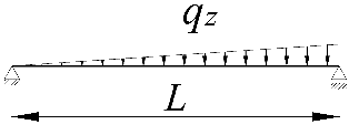 IPE300, L = 5m zg = +h/2 | 1 | 0 | 180.60 | 181.99 | 0.8 |
| 8 | 0.8 | 0.2 | 134.02 | 134.00 | 0 | |
| 9 | 0.6 | 0.4 | 109.13 | 106.51 | −2.4 | |
| 10 | 0.4 | 0.564 | 93.77 | 89.01 | −5.1 | |
| 11 | 0.2 | 0.8 | 124.77 | 116.88 | −6.3 | |
| 12 | 0 | 1 | 146.70 | 154.68 | 5.4 | |
| Item | Static Scheme | Equation (13) vs. LTBeamN (%) | |
|---|---|---|---|
| I | II | III | IV |
| 1 | 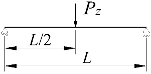 | zg = +h/2 | −3.7 ÷ 4.4 |
| 2 | zg = 0 | −1.7 ÷ 3.9 | |
| 3 | zg = −h/2 | −2.4 ÷ 5.5 | |
| 4 |  | zg = +h/2 | −5.2 ÷ 3.4 |
| 5 | zg = 0 | −0.6 ÷ 4.8 | |
| 6 | zg = −h/2 | −6.0 ÷ 5.5 | |
| 7 | 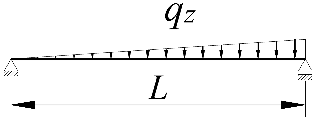 | zg = +h/2 | −7.1 ÷ 6.6 |
| 8 | zg = 0 | −1.4 ÷ 5.4 | |
| 9 | zg = −h/2 | −6.1 ÷ 6.7 | |
Publisher’s Note: MDPI stays neutral with regard to jurisdictional claims in published maps and institutional affiliations. |
© 2022 by the authors. Licensee MDPI, Basel, Switzerland. This article is an open access article distributed under the terms and conditions of the Creative Commons Attribution (CC BY) license (https://creativecommons.org/licenses/by/4.0/).
Share and Cite
Piotrowski, R.; Szychowski, A. The Effect of Steel Beam Elastic Restraint on the Critical Moment of Lateral Torsional Buckling. Materials 2022, 15, 1275. https://doi.org/10.3390/ma15041275
Piotrowski R, Szychowski A. The Effect of Steel Beam Elastic Restraint on the Critical Moment of Lateral Torsional Buckling. Materials. 2022; 15(4):1275. https://doi.org/10.3390/ma15041275
Chicago/Turabian StylePiotrowski, Rafał, and Andrzej Szychowski. 2022. "The Effect of Steel Beam Elastic Restraint on the Critical Moment of Lateral Torsional Buckling" Materials 15, no. 4: 1275. https://doi.org/10.3390/ma15041275
APA StylePiotrowski, R., & Szychowski, A. (2022). The Effect of Steel Beam Elastic Restraint on the Critical Moment of Lateral Torsional Buckling. Materials, 15(4), 1275. https://doi.org/10.3390/ma15041275