
Electrochemical Synthesis of Zinc Oxide Nanostructures on Flexible Substrate and Application as an Electrochemical Immunoglobulin-G Immunosensor

 , ,
, ,  and
and 
Abstract
1. Introduction
2. Materials and Methods
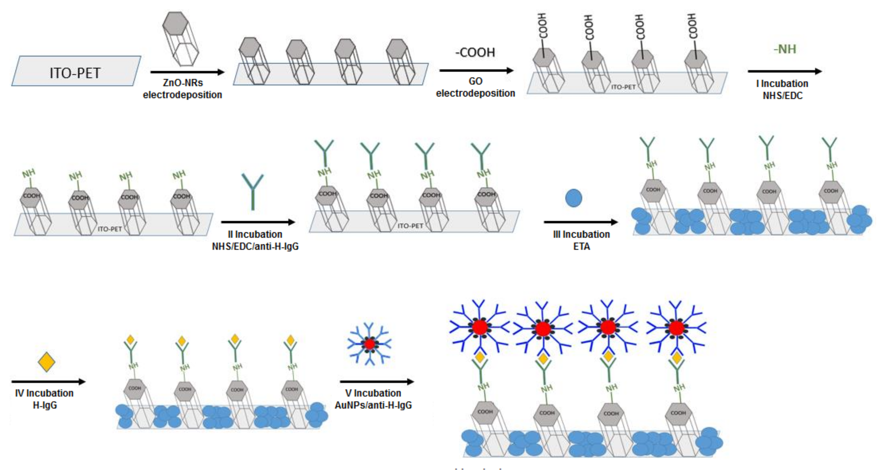
2.1. Fabrication of ZnO-NRs/rGO
2.2. Fabrication of Immunosensors
3. Results and Discussion
4. Conclusions
Author Contributions
Funding
Institutional Review Board Statement
Informed Consent Statement
Data Availability Statement
Conflicts of Interest
References
- Barbosa, H.P.; Araújo, D.A.G.; Pradela-Filho, L.A.; Takeuchi, R.M.; de Lima, R.G.; Ferrari, J.L.; Sousa Góes, M.; dos Santos, A.L. Zinc Oxide as a Multifunctional Material: From Biomedical Applications to Energy Conversion and Electrochemical Sensing. In Metal and Metal Oxides for Energy and Electronics; Rajendran, S., Qin, J., Gracia, F., Lichtfouse, E., Eds.; Springer International Publishing: Cham, Switzerland, 2021; pp. 251–305. [Google Scholar] [CrossRef]
- Fortunato, E.; Gonçalves, A.; Pimentel, A.; Barquinha, P.; Pereira, L.; Ferreira, I.; Martins, R. Zinc oxide, a multifunctional material: From material to device applications. Appl. Phys. A 2009, 96, 197–205. [Google Scholar] [CrossRef]
- Srikant, V.; Clarke, D.R. On the optical band gap of zinc oxide. J. Appl. Phys. 1998, 83, 5447–5451. [Google Scholar] [CrossRef]
- Inguanta, R.; Garlisi, C.; Spanò, T.; Piazza, S.; Sunseri, C. Growth and photoelectrochemical behaviour of electrodeposited ZnO thin films for solar cells. J. Appl. Electrochem. 2012, 43, 199–208. [Google Scholar] [CrossRef]
- Larsson, L.F.G.; Maia, G.A.R.; Tractz, G.T.; Valério, T.L.; Oliszeski, D.C.S.; Helleis, R.; Da Cunha, M.T.; Rodrigues, P.R.P.; Banczek, E.D.P. Application of Zinc Oxide in Hybrid Solar Cells Using a P3HT and P3OT Polymer Junction as Charge Carrier. Mater. Res. 2019, 22, 0820. [Google Scholar] [CrossRef]
- Moret, M.; Chaaya, A.A.; Bechelany, M.; Miele, P.; Robin, Y.; Briot, O. Atomic Layer Deposition of zinc oxide for solar cell applications. Superlattices Microstruct. 2014, 75, 477–484. [Google Scholar] [CrossRef]
- Vittal, R.; Ho, K.-C. Zinc oxide based dye-sensitized solar cells: A review. Renew. Sustain. Energy Rev. 2016, 70, 920–935. [Google Scholar] [CrossRef]
- Priyanka, N.; Geetha, N.; Ghorbanpour, M.; Venkatachalam, P. Role of Engineered Zinc and Copper Oxide Nanoparticles in Promoting Plant Growth and Yield: Present Status and Future Prospects. In Advances in Phytonanotechnology; Academic Press: Cambridge, MA, USA, 2019; pp. 183–201. [Google Scholar] [CrossRef]
- Espitia, P.J.P.; Otoni, C.G.; Soares, N.F.F. Zinc Oxide Nanoparticles for Food Packaging Applications. In Antimicrobal and Food Packaging; Academic Press: Cambridge, MA, USA, 2016; pp. 425–431. [Google Scholar] [CrossRef]
- Chaudhary, S.; Umar, A.; Bhasin, K.K.; Baskoutas, S. Chemical Sensing Applications of ZnO Nanomaterials. Materials 2018, 11, 287. [Google Scholar] [CrossRef]
- Gumpu, M.B.; Nesakumar, N.; Ramachandra, B.L.; Rayappan, J.B.B. Zinc oxide nanoparticles-based electrochemical sensor for the detection of nitrate ions in water with a low detection limit—A chemometric approach. J. Anal. Chem. 2017, 72, 316–326. [Google Scholar] [CrossRef]
- Liu, P.T.; Ruan, D.B.; Yeh, X.Y.; Chiu, Y.C.; Zheng, G.T.; Sze, S.M. Highly Responsive Blue Light Sensor with Amorphous Indium-Zinc-Oxide Thin-Film Transistor based Architecture. Sci. Rep. 2018, 8, 8153. [Google Scholar] [CrossRef]
- Rahman, F. Zinc oxide light-emitting diodes: A review. Opt. Eng. 2019, 58, 010901. [Google Scholar] [CrossRef]
- Deschanvres, J.-L.; Rey, P.; Delabouglise, G.; LaBeau, M.; Joubert, J.; Peuzin, J. Characterization of piezoelectric properties of zinc oxide thin films deposited on silicon for sensors applications. Sens. Actuators A Phys. 1992, 33, 43–45. [Google Scholar] [CrossRef]
- Wang, X.; Li, X.; Zhang, Q.; Lu, Z.; Song, H.; Wang, Y. Electrodeposition of ZnO Nanorods with Synergistic Photocatalytic and Self-Cleaning Effects. J. Electron. Mater. 2021, 50, 4954–4961. [Google Scholar] [CrossRef]
- Vaghayenegar, M.; Kermanpur, A.; Abbasi, M. Formation mechanism of ZnO nanorods produced by the electromagnetic levitational gas condensation method. Sci. Iran. 2011, 18, 1647–1651. [Google Scholar] [CrossRef][Green Version]
- Black, K.; Chalker, P.R.; Jones, A.C.; King, P.J.; Roberts, J.L.; Heys, P.N. A New Method for the Growth of Zinc Oxide Nanowires by MOCVD using Oxygen-Donor Adducts of Dimethylzinc. Chem. Vap. Depos. 2010, 16, 106–111. [Google Scholar] [CrossRef]
- Sbrockey, N.M.; Ganesan, S. ZnO thin films by MOCVD. III-Vs Rev. 2004, 17, 23–25. [Google Scholar] [CrossRef]
- Maruyama, T.; Shionoya, J. Zinc oxide thin films prepared by chemical vapour deposition from zinc acetate. J. Mater. Sci. Lett. 1992, 11, 170–172. [Google Scholar] [CrossRef]
- Ellmer, K. Magnetron sputtering of transparent conductive zinc oxide: Relation between the sputtering parameters and the electronic properties. J. Phys. D Appl. Phys. 2000, 33, R17–R32. [Google Scholar] [CrossRef]
- Dave, P.Y.; Patel, K.H.; Chauhan, K.V.; Chawla, A.K.; Rawal, S.K. Examination of Zinc Oxide Films Prepared by Magnetron Sputtering. Procedia Technol. 2016, 23, 328–335. [Google Scholar] [CrossRef]
- Damiani, L.R.; Mansano, R.D. Zinc oxide thin films deposited by magnetron sputtering with various oxygen/argon concentrations. J. Phys. Conf. Ser. 2012, 370, 012019. [Google Scholar] [CrossRef]
- Kumar, M.; Sasikumar, C. Electrodeposition of Nanostructured ZnO Thin Film: A Review. Am. J. Mater. Sci. Eng. 2014, 2, 18–23. [Google Scholar] [CrossRef]
- Haque, J.; Bellah, M.; Hassan, R.; Rahman, S. Synthesis of ZnO nanoparticles by two different methods & comparison of their structural, antibacterial, photocatalytic and optical properties. Nano Express 2020, 1, 010007. [Google Scholar] [CrossRef]
- Wojnarowicz, J.; Chudoba, T.; Lojkowski, W. A Review of Microwave Synthesis of Zinc Oxide Nanomaterials: Reactants, Process Parameters and Morphologies. Nanomaterials 2020, 10, 1086. [Google Scholar] [CrossRef]
- Dien, N.D. Preparation of various morphologies of ZnO nanostructure through wet chemical methods. Adv. Mater. Sci. 2019, 4, 1–5. [Google Scholar] [CrossRef]
- Inguanta, R.; Piazza, S.; Sunseri, C. A Route to Grow Oxide Nanostructures Based on Metal Displacement Deposition: Lanthanides Oxy/Hydroxides Characterization. J. Electrochem. Soc. 2012, 159, D493–D500. [Google Scholar] [CrossRef]
- Indira, L.; Kamath, P.V. Electrogeneration of base by cathodic reduction of anions: Novel one-step route to unary and layered double hydroxides (LDHs). J. Mater. Chem. 1994, 4, 1487–1490. [Google Scholar] [CrossRef]
- Blanda, G.; Brucato, V.M.B.; Pavia, F.C.; Greco, S.; Piazza, S.; Sunseri, C.; Inguanta, R. Galvanic deposition and characterization of brushite/hydroxyapatite coatings on 316L stainless steel. Mater. Sci. Eng. C 2016, 64, 93–101. [Google Scholar] [CrossRef]
- Inguanta, R.; Ferrara, G.; Piazza, S.; Sunseri, C. A new route to grow oxide nanostructures based on metal displacement deposition. Lanthanides oxy/hydroxides growth. Electrochim. Acta 2012, 76, 77–87. [Google Scholar] [CrossRef]
- Nobial, M.; Devos, O.; Mattos, O.R.; Tribollet, B. The nitrate reduction process: A way for increasing interfacial pH. J. Electroanal. Chem. 2007, 600, 87–94. [Google Scholar] [CrossRef]
- Izaki, M.; Omi, T. Transparent zinc oxide films prepared by electrochemical reaction. Appl. Phys. Lett. 1996, 68, 2439–2440. [Google Scholar] [CrossRef]
- Peulon, S.; Lincot, D. Cathodic electrodeposition from aqueous solution of dense or open-structured zinc oxide films. Adv. Mater. 1996, 8, 166–170. [Google Scholar] [CrossRef]
- Yoshida, T.; Komatsu, D.; Shimokawa, N.; Minoura, H. Mechanism of cathodic electrodeposition of zinc oxide thin films from aqueous zinc nitrate baths. Thin Solid Films 2004, 451–452, 166–169. [Google Scholar] [CrossRef]
- Marimuthu, T.; Anandhan, N. Effect of polyvinyl alcohol on electrochemically deposited ZnO thin films for DSSC applications. AIP Conf. Proc. 2017, 1832, 80014. [Google Scholar] [CrossRef]
- Ahmad, M.; Yingying, S.; Nisar, A.; Sun, H.; Shen, W.; Wei, M.; Zhu, J. Synthesis of hierarchical flower-like ZnO nanostructures and their functionalization by Au nanoparticles for improved photocatalytic and high performance Li-ion battery anodes. J. Mater. Chem. 2011, 21, 7723–7729. [Google Scholar] [CrossRef]
- Marimuthu, T.; Anandhan, N.; Thangamuthu, R. Electrochemical synthesis of one-dimensional ZnO nanostructures on ZnO seed layer for DSSC applications. Appl. Surf. Sci. 2018, 428, 385–394. [Google Scholar] [CrossRef]
- Ko, Y.H.; Ramana, D.K.V.; Yu, J.S. Electrochemical synthesis of ZnO branched submicrorods on carbon fibers and their feasibility for environmental applications. Nanoscale Res. Lett. 2013, 8, 1–7. [Google Scholar] [CrossRef]
- Pourmortazavi, S.M.; Marashianpour, Z.; Karimi, M.S.; Mohammad-Zadeh, M. Electrochemical synthesis and characterization of zinc carbonate and zinc oxide nanoparticles. J. Mol. Struct. 2015, 1099, 232–238. [Google Scholar] [CrossRef]
- Marimuthu, T.; Anandhan, N. Growth and characterization of ZnO nanostructure on TiO2-ZnO films as a light scattering layer for dye sensitized solar cells. Mater. Res. Bull. 2017, 95, 616–624. [Google Scholar] [CrossRef]
- Starowicz, M.; Stypuła, B. Electrochemical Synthesis of ZnO Nanoparticles. Eur. J. Inorg. Chem. 2008, 2008, 869–872. [Google Scholar] [CrossRef]
- Marimuthu, T.; Anandhan, N.; Thangamuthu, R.; Surya, S. Effect of hexamethylenetetramine on the properties of electrodeposited ZnO thin films for dye sensitized solar cell applications. J. Mater. Sci. Mater. Electron. 2018, 29, 12830–12841. [Google Scholar] [CrossRef]
- Dimova-Malnovska, D.; Andreev, P.; Sendova-Vassileva, M.; Nichev, H.; Starbova, K. Preparation of ZnO nanowires by electrochemical deposition. Energy Procedia 2010, 2, 55–58. [Google Scholar] [CrossRef][Green Version]
- Park, S.K.; Park, J.H.; Ko, K.Y.; Yoon, S.; Chu, K.S.; Kim, W.; Do, Y.R. Hydrothermal−Electrochemical Synthesis of ZnO Nanorods. Cryst. Growth Des. 2009, 9, 3615–3620. [Google Scholar] [CrossRef]
- Marimuthu, T.; Anandhan, N.; Thangamuthu, R. A facile electrochemical–hydrothermal synthesis and characterization of zinc oxide hierarchical structure for dye sensitized solar cell applications. J. Mater. Sci. 2018, 53, 12441–12454. [Google Scholar] [CrossRef]
- Skompska, M.; Zarebska, K. Electrodeposition of ZnO Nanorod Arrays on Transparent Conducting Substrates—A Review. Electrochim. Acta 2014, 127, 467–488. [Google Scholar] [CrossRef]
- Chen, J.; Zhang, Y.; Qiu, W.; Chen, S.; Liu, C.; Peng, Z.; Chen, J. Mechanism and Optimized Process Conditions of Forming One-Dimensional ZnO Nanorods with Al-Doping by Electrodeposition Method. Int. J. Photoenergy 2021, 2021, 1–13. [Google Scholar] [CrossRef]
- Inguanta, R.; Rinaldo, E.; Piazza, S.; Sunseri, C. Lead Nanowires for Microaccumulators Obtained Through Indirect Electrochemical Template Deposition. Electrochem. Solid-State Lett. 2010, 13, K1–K4. [Google Scholar] [CrossRef]
- Insinga, M.G.; Oliveri, R.L.; Sunseri, C.; Inguanta, R. Template electrodeposition and characterization of nanostructured Pb as a negative electrode for lead-acid battery. J. Power Sources 2018, 413, 107–116. [Google Scholar] [CrossRef]
- Battaglia, M.; Inguanta, R.; Piazza, S.; Sunseri, C. Fabrication and characterization of nanostructured Ni–IrO2 electrodes for water electrolysis. Int. J. Hydrogen Energy 2014, 39, 16797–16805. [Google Scholar] [CrossRef]
- Ganci, F.; Lombardo, S.; Sunseri, C.; Inguanta, R. Nanostructured electrodes for hydrogen production in alkaline electrolyzer. Renew. Energy 2018, 123, 117–124. [Google Scholar] [CrossRef]
- Buccheri, B.; Ganci, F.; Patella, B.; Aiello, G.; Mandin, P.; Inguanta, R. Ni-Fe alloy nanostructured electrodes for water splitting in alkaline electrolyser. Electrochim. Acta 2021, 388, 138588. [Google Scholar] [CrossRef]
- Battaglia, M.; Piazza, S.; Sunseri, C.; Inguanta, R. Amorphous silicon nanotubes via galvanic displacement deposition. Electrochem. Commun. 2013, 34, 134–137. [Google Scholar] [CrossRef]
- Inguanta, R.; Piazza, S.; Sunseri, C.; Cino, A.; Di Dio, V.; La Cascia, D.; Miceli, R.; Rando, C.; Zizzo, G. An electrochemical route towards the fabrication of nanostructured semiconductor solar cells. SPEEDAM 2010 2010, 1166–1171. [Google Scholar] [CrossRef]
- Tishkevich, D.; Vorobjova, A.; Shimanovich, D.; Kaniukov, E.; Kozlovskiy, A.; Zdorovets, M.; Vinnik, D.; Turutin, A.; Kubasov, I.; Kislyuk, A.; et al. Magnetic Properties of the Densely Packed Ultra-Long Ni Nanowires Encapsulated in Alumina Membrane. Nanomaterials 2021, 11, 1775. [Google Scholar] [CrossRef]
- Vorobjova, A.; Tishkevich, D.; Shimanovich, D.; Zubar, T.; Astapovich, K.; Kozlovskiy, A.; Zdorovets, M.; Zhaludkevich, A.; Lyakhov, D.; Michels, D.; et al. The influence of the synthesis conditions on the magnetic behaviour of the densely packed arrays of Ni nanowires in porous anodic alumina membranes. RSC Adv. 2021, 11, 3952–3962. [Google Scholar] [CrossRef]
- Sunseri, C.; Cocchiara, C.; Ganci, F.; Moncada, A.; Oliveri, R.L.; Patella, B.; Piazza, S.; Inguanta, R. Nanostructured electrochemical devices for sensing, energy conversion and storage. Chem. Eng. Trans. 2016, 47, 43–48. [Google Scholar] [CrossRef]
- Patella, B.; Russo, R.; O’Riordan, A.; Aiello, G.; Sunseri, C.; Inguanta, R. Copper nanowire array as highly selective electrochemical sensor of nitrate ions in water. Talanta 2020, 221, 121643. [Google Scholar] [CrossRef]
- Trujillo, R.; Barraza, D.; Zamora, M.; Cattani-Scholz, A.; Madrid, R. Nanostructures in Hydrogen Peroxide Sensing. Sensors 2021, 21, 2204. [Google Scholar] [CrossRef] [PubMed]
- Robinson, C.; Creedon, N.; Sayers, R.; Kennedy, E.; O’Riordan, A. Electrochemical detection of bovine immunoglobulins G to determine passive transfer of antibodies to calves. Anal. Methods 2020, 12, 2655–2660. [Google Scholar] [CrossRef]
- Park, J.; You, X.; Jang, Y.; Nam, Y.; Kim, M.J.; Min, N.K.; Pak, J.J. ZnO nanorod matrix based electrochemical immunosensors for sensitivity enhanced detection of Legionella pneumophila. Sens. Actuators B Chem. 2014, 200, 173–180. [Google Scholar] [CrossRef]
- Vabbina, P.K.; Kaushik, A.; Pokhrel, N.; Bhansali, S.; Pala, N. Electrochemical cortisol immunosensors based on sonochemically synthesized zinc oxide 1D nanorods and 2D nanoflakes. Biosens. Bioelectron. 2015, 63, 124–130. [Google Scholar] [CrossRef] [PubMed]
- Gasparotto, G.; Costa, J.P.; Costa, P.I.; Zaghete, M.; Mazon, T. Electrochemical immunosensor based on ZnO nanorods-Au nanoparticles nanohybrids for ovarian cancer antigen CA-125 detection. Mater. Sci. Eng. C 2017, 76, 1240–1247. [Google Scholar] [CrossRef]
- Martins, B.; Sampaio, T.; de Farias, A.; Martins, R.d.P.; Teixeira, R.; Oliveira, R.; Oliveira, C.; da Silva, M.; Rodrigues, V.; Dantas, N.; et al. Immunosensor Based on Zinc Oxide Nanocrystals Decorated with Copper for the Electrochemical Detection of Human Salivary Alpha-Amylase. Micromachines 2021, 12, 657. [Google Scholar] [CrossRef] [PubMed]
- Tabatabaei, M.K.; Fard, H.G.; Koohsorkhi, J.; Arough, J.M. High-performance immunosensor for urine albumin using hybrid architectures of ZnO nanowire/carbon nanotube. IET Nanobiotechnol. 2020, 14, 126–132. [Google Scholar] [CrossRef] [PubMed]
- Koike, K.; Mukai, K.; Onaka, T.; Maemoto, T.; Sasa, S.; Yano, M. A potentiometric immunosensor based on a ZnO field-effect transistor. Jpn. J. Appl. Phys. 2014, 53, 05FF04. [Google Scholar] [CrossRef]
- Dong, S.; Tong, M.; Zhang, D.; Huang, T. The strategy of nitrite and immunoassay human IgG biosensors based on ZnO@ZIF-8 and ionic liquid composite film. Sens. Actuators B Chem. 2017, 251, 650–657. [Google Scholar] [CrossRef]
- Chen, L.Y.; Tee, C.K.; Chortos, A.; Schwartz, G.; Tse, V.; Lipomi, D.J.; Wong, H.-S.P.; McConnell, M.; Bao, Z. Continuous wireless pressure monitoring and mapping with ultra-small passive sensors for health monitoring and critical care. Nat. Commun. 2014, 5, 1–10. [Google Scholar] [CrossRef] [PubMed]
- Lee, H.; Choi, T.K.; Lee, Y.B.; Cho, H.R.; Ghaffari, R.; Wang, L.; Choi, H.J.; Chung, T.D.; Lu, N.; Hyeon, T.; et al. A graphene-based electrochemical device with thermoresponsive microneedles for diabetes monitoring and therapy. Nat. Nanotechnol. 2016, 11, 566–572. [Google Scholar] [CrossRef] [PubMed]
- Patella, B.; Buscetta, M.; Di Vincenzo, S.; Ferraro, M.; Aiello, G.; Sunseri, C.; Pace, E.; Inguanta, R.; Cipollina, C. Electrochemical sensor based on rGO/Au nanoparticles for monitoring H2O2 released by human macrophages. Sens. Actuators B Chem. 2020, 327, 128901. [Google Scholar] [CrossRef]
- Madden, J.; O’Mahony, C.; Thompson, M.; O’Riordan, A.; Galvin, P. Biosensing in dermal interstitial fluid using microneedle based electrochemical devices. Sens. Bio-Sens. Res. 2020, 29, 100348. [Google Scholar] [CrossRef]
- Cai, Y.; Shen, J.; Dai, Z.; Zang, X.; Dong, Q.; Guan, G.; Li, L.; Huang, W.; Dong, X. Extraordinarily Stretchable All-Carbon Collaborative Nanoarchitectures for Epidermal Sensors. Adv. Mater. 2017, 29, 1606411. [Google Scholar] [CrossRef]
- Struzik, M.; Garbayo, I.; Pfenninger, R.; Rupp, J.L.M. A Simple and Fast Electrochemical CO2Sensor Based on Li7La3Zr2O12for Environmental Monitoring. Adv. Mater. 2018, 30, e1804098. [Google Scholar] [CrossRef]
- Patella, B.; Aiello, G.; Drago, G.; Torino, C.; Vilasi, A.; O’Riordan, A.; Inguanta, R. Electrochemical detection of chloride ions using Ag-based electrodes obtained from compact disc. Anal. Chim. Acta 2021, 1190, 339215. [Google Scholar] [CrossRef]
- Seymour, I.; Narayan, T.; Creedon, N.; Kennedy, K.; Murphy, A.; Sayers, R.; Kennedy, E.; O’Connell, I.; Rohan, J.; O’Riordan, A. Advanced Solid State Nano-Electrochemical Sensors and System for Agri 4.0 Applications. Sensors 2021, 21, 3149. [Google Scholar] [CrossRef]
- Kim, Y.; Johnson, A.R.C.; Hupp, J.T. Gold Nanoparticle-Based Sensing of “Spectroscopically Silent” Heavy Metal Ions. Nano Lett. 2001, 1, 165–167. [Google Scholar] [CrossRef]
- Wasiewska, L.A.; Seymour, I.; Patella, B.; Inguanta, R.; Burgess, C.M.; Duffy, G.; O’Riordan, A. Reagent free electrochemical-based detection of silver ions at interdigitated microelectrodes using in-situ pH control. Sens. Actuators B Chem. 2021, 333, 129531. [Google Scholar] [CrossRef]
- Seymour, I.; O’Sullivan, B.; Lovera, P.; Rohan, J.F.; O’Riordan, A. Electrochemical detection of free-chlorine in Water samples facilitated by in-situ pH control using interdigitated microelectrodes. Sens. Actuators B Chem. 2020, 325, 128774. [Google Scholar] [CrossRef]
- O’Sullivan, B.; Patella, B.; Daly, R.; Seymour, I.; Robinson, C.; Lovera, P.; Rohan, J.; Inguanta, R.; O’Riordan, A. A simulation and experimental study of electrochemical pH control at gold interdigitated electrode arrays. Electrochim. Acta 2021, 395, 139113. [Google Scholar] [CrossRef]
- Nio thin film for mercury detection in water by square wave anodic stripping voltammetry. Chem. Eng. Trans. 2017, 60, 1–6. [CrossRef]
- Mazzara, F.; Patella, B.; Aiello, G.; Sunseri, C.; Inguanta, R. Ascorbic Acid determination using linear sweep voltammetry on flexible electrode modified with gold nanoparticles and reduced graphene oxide. In Proceedings of the 2020 IEEE 20th Mediterranean Electrotechnical Conference (MELECON), Palermo, Italy, 16–18 June 2020; pp. 406–410. [Google Scholar] [CrossRef]
- Guillem, P.; Bustos, R.-H.; Garzon, V.; Munoz, A.; Juez, G. A low-cost electrochemical biosensor platform for C-reactive protein detection. Sens. Bio-Sens. Res. 2021, 31, 100402. [Google Scholar] [CrossRef]
- Pollap, A.; Kochana, J. Electrochemical Immunosensors for Antibiotic Detection. Biosensors 2019, 9, 61. [Google Scholar] [CrossRef]
- Chikkaveeraiah, B.V.; Bhirde, A.A.; Morgan, N.Y.; Eden, H.S.; Chen, X. Electrochemical Immunosensors for Detection of Cancer Protein Biomarkers. ACS Nano 2012, 6, 6546–6561. [Google Scholar] [CrossRef]
- Aizawa, M.; Morioka, A.; Suzuki, S. Enzyme immunosensor: II. Electrochemical determination of IgG with an antibodybound membrane. J. Membr. Sci. 1979, 4, 221–228. [Google Scholar] [CrossRef]
- Metzner, J.; Luckert, K.; Lemuth, K.; Hämmerle, M.; Moos, R. Towards an Electrochemical Immunosensor System with Temperature Control for Cytokine Detection. Sensors 2018, 18, 1309. [Google Scholar] [CrossRef] [PubMed]
- Sharma, A.; Rao, V.K.; Kamboj, D.V.; Jain, R. Electrochemical Immunosensor for Staphylococcal Enterotoxin B (SEB) Based on Platinum Nanoparticles-Modified Electrode Using Hydrogen Evolution Inhibition Approach. Electroanalysis 2014, 26, 2320–2327. [Google Scholar] [CrossRef]
- Hao, N.; Li, H.; Long, Y.; Zhang, L.; Zhao, X.; Xu, D.; Chen, H.-Y. An electrochemical immunosensing method based on silver nanoparticles. J. Electroanal. Chem. 2011, 656, 50–54. [Google Scholar] [CrossRef]
- Monerris, M.J.; D’eramo, F.; Arévalo, F.J.; Fernández, H.; Zon, M.A.; Molina, P.G. Electrochemical immunosensor based on gold nanoparticles deposited on a conductive polymer to determine estrone in water samples. Microchem. J. 2016, 129, 71–77. [Google Scholar] [CrossRef]
- Beck, F.; Horn, C.; Baeumner, A.J. Ag nanoparticles outperform Au nanoparticles for the use as label in electrochemical point-of-care sensors. Anal. Bioanal. Chem. 2021, 414, 475–483. [Google Scholar] [CrossRef]
- Yuan, F.; Peng, H.; Yin, Y.; Chunlei, Y.; Ryu, H. Preparation of zinc oxide nanoparticles coated with homogeneous Al2O3 layer. Mater. Sci. Eng. B 2005, 122, 55–60. [Google Scholar] [CrossRef]
- Zhai, J.; Tao, X.; Pu, Y.; Zeng, X.-F.; Chen, J.-F. Core/shell structured ZnO/SiO2 nanoparticles: Preparation, characterization and photocatalytic property. Appl. Surf. Sci. 2010, 257, 393–397. [Google Scholar] [CrossRef]
- Tso, C.-P.; Zhung, C.-M.; Shih, Y.-H.; Tseng, Y.-M.; Wu, S.-C.; Doong, R.-A. Stability of metal oxide nanoparticles in aqueous solutions. Water Sci. Technol. 2010, 61, 127–133. [Google Scholar] [CrossRef]
- Shetti, N.P.; Bukkitgar, S.D.; Reddy, K.R.; Reddy, C.V.; Aminabhavi, T.M. ZnO-Based Nanostructured Electrodes for Electrochemical Sensors and Biosensors in Biomedical Applications. Biosensors and Bioelectronics 2019, 141, 111417. [Google Scholar] [CrossRef]
- Gosai, A.; Khondakar, K.R.; Ma, X.; Ali, A. Application of Functionalized Graphene Oxide Based Biosensors for Health Monitoring: Simple Graphene Derivatives to 3D Printed Platforms. Biosensors 2021, 11, 384. [Google Scholar] [CrossRef]
- Ali, M.A.; Hu, C.; Jahan, S.; Yuan, B.; Saleh, M.S.; Ju, E.; Gao, S.J.; Panat, R. Sensing of COVID-19 Antibodies in Seconds via Aerosol Jet Nanoprinted Reduced-Graphene-Oxide-Coated 3D Electrodes. Adv. Mater. 2021, 33, e2006647. [Google Scholar] [CrossRef]
- Silipigni, L.; Barreca, F.; Fazio, E.; Neri, F.; Spanò, T.; Piazza, S.; Sunseri, C.; Inguanta, R. Template Electrochemical Growth and Properties of Mo Oxide Nanostructures. J. Phys. Chem. C 2014, 118, 22299–22308. [Google Scholar] [CrossRef]
- Inguanta, R.; Ferrara, G.; Piazza, S.; Sunseri, C. Nanostructure fabrication by template deposition into anodic alumina membranes. Chem. Eng. Trans. 2009, 17, 957–962. [Google Scholar] [CrossRef]
- Mazzara, F.; Patella, B.; Aiello, G.; O’Riordan, A.; Torino, C.; Vilasi, A.; Inguanta, R. Electrochemical detection of uric acid and ascorbic acid using r-GO/NPs based sensors. Electrochim. Acta 2021, 388, 138652. [Google Scholar] [CrossRef]
- Mazzara, F.; Patella, B.; D’Agostino, C.; Bruno, M.; Carbone, S.; Lopresti, F.; Aiello, G.; Torino, C.; Vilasi, A.; O’Riordan, A.; et al. PANI-Based Wearable Electrochemical Sensor for pH Sweat Monitoring. Chemosensors 2021, 9, 169. [Google Scholar] [CrossRef]
- Patella, B.; Inguanta, R.; Piazza, S.; Sunseri, C. Nanowire ordered arrays for electrochemical sensing of h2o2. Chem. Eng. Trans. 2016, 47, 19–24. [Google Scholar] [CrossRef]
- Patella, B.; Russo, R.R.; Aiello, G.; Sunseri, C.; Inguanta, R. Vertical standing copper nanowires for electrochemical sensor of nitrate in water. In Proceedings of the 2020 IEEE International Conference on Flexible and Printable Sensors and Systems (FLEPS), IEEE, Manchester, UK, 16–19 August 2020; pp. 1–4. [Google Scholar] [CrossRef]
- Kimling, J.; Maier, M.; Okenve, B.; Kotaidis, V.; Ballot, H.; Plech, A. Turkevich Method for Gold Nanoparticle Synthesis Revisited. J. Phys. Chem. B 2006, 110, 15700–15707. [Google Scholar] [CrossRef]
- Solís, D.; Jiménez, F.D.P.M.; Schrebler, R.S.; Astorga, E.N.; Escalante, M.C.L.; Pérez, J.J.P.; Barrado, J.R.R.; Dalchiele, E.A. Electrochemical growth of ZnO nanorod arrays onto transparent conductive IZO:Ga substrates. J. Electrochem. Soc. 2020, 167, 112504. [Google Scholar] [CrossRef]
- Tolosa, M.D.R.; Damonte, L.C.; Brine, H.; Bolink, H.J.; A Hernández-Fenollosa, M. Nucleant layer effect on nanocolumnar ZnO films grown by electrodeposition. Nanoscale Res. Lett. 2013, 8, 1–6. [Google Scholar] [CrossRef]
- Jiangfeng, G.; Zhaoming, D.; Qingping, D.; Yuan, X.; Weihua, Z. Controlled Synthesis of ZnO Nanostructures by Electrodeposition Method. J. Nanomater. 2010, 2010, 1–6. [Google Scholar] [CrossRef]
- Ardakani, A.G.; Rafieipour, P. Using ZnO nanosheets grown by electrodeposition in random lasers as scattering centers: The effects of sheet size and presence of mode competition. J. Opt. Soc. Am. B 2018, 35, 1708–1716. [Google Scholar] [CrossRef]
- Ghannam, H.; Bazin, C.; Chahboun, A.; Turmine, M. Control of the growth of electrodeposited zinc oxide on FTO glass. CrystEngComm 2018, 20, 6618–6628. [Google Scholar] [CrossRef]
- Shinagawa, T.; Izaki, M. Morphological evolution of ZnO nanorod arrays induced by a pH-buffering effect during electrochemical deposition. RSC Adv. 2014, 4, 30999–31002. [Google Scholar] [CrossRef]
- Romero, M.; Química, F.D.C.I.D. Electrochemical Deposition of ZnO Nanorod Arrays onto a ZnO Seed Layer: Nucleation and Growth Mechanism. Int. J. Electrochem. Sci. 2016, 11, 8588–8598. [Google Scholar] [CrossRef]
- Illy, B.N.; Cruickshank, A.C.; Schumann, S.; Da Campo, R.; Jones, T.S.; Heutz, S.; McLachlan, M.A.; McComb, D.W.; Riley, D.J.; Ryan, M.P. Electrodeposition of ZnO layers for photovoltaic applications: Controlling film thickness and orientation. J. Mater. Chem. 2011, 21, 12949–12957. [Google Scholar] [CrossRef]
- Ghannam, H.; Chahboun, A.; Turmine, M. Wettability of zinc oxide nanorod surfaces. RSC Adv. 2019, 9, 38289–38297. [Google Scholar] [CrossRef]
- Jang, E.S.; Won, J.-H.; Hwang, S.-J.; Choy, J.-H. Fine Tuning of the Face Orientation of ZnO Crystals to Optimize Their Photocatalytic Activity. Adv. Mater. 2006, 18, 3309–3312. [Google Scholar] [CrossRef]
- Lu, H.; Li, X.; Zhang, Z.; Shao, G. One-step microwave synthesis of Ag/ZnO microrods as photocatalysts. Mater. Res. Innov. 2017, 23, 129–134. [Google Scholar] [CrossRef]
- Patella, B.; Sortino, A.; Aiello, G.; Sunseri, C.; Inguanta, R. Reduced graphene oxide decorated with metals nanoparticles electrode as electrochemical sensor for dopamine. In Proceedings of the 2019 IEEE International Conference on Flexible and Printable Sensors and Systems (FLEPS), IEEE, Glasgow, UK, 8–10 July 2019; pp. 1–3. [Google Scholar] [CrossRef]
- Zhou, M.; Wang, Y.; Zhai, Y.; Zhai, J.; Ren, W.; Wang, F.; Dong, S. Controlled Synthesis of Large-Area and Patterned Electrochemically Reduced Graphene Oxide Films. Chem. A Eur. J. 2009, 15, 6116–6120. [Google Scholar] [CrossRef] [PubMed]
- Rosas-Laverde, N.M.; Pruna, A.; Busquets-Mataix, D.; Pullini, D. Graphene Oxide-Assisted Morphology and Structure of Electrodeposited ZnO Nanostructures. Materials 2020, 13, 365. [Google Scholar] [CrossRef] [PubMed]
- Patella, B.; Sortino, A.; Mazzara, F.; Aiello, G.; Drago, G.; Torino, C.; Vilasi, A.; O’Riordan, A.; Inguanta, R. Electrochemical detection of dopamine with negligible interference from ascorbic and uric acid by means of reduced graphene oxide and metals-NPs based electrodes. Anal. Chim. Acta 2021, 1187, 339124. [Google Scholar] [CrossRef] [PubMed]
- Wang, Z.; Yang, Y.; Li, J.; Gong, J.; Shen, G.; Yu, R. Organic–inorganic matrix for electrochemical immunoassay: Detection of human IgG based on ZnO/chitosan composite. Talanta 2006, 69, 686–690. [Google Scholar] [CrossRef] [PubMed]
- Tang, D.; Yuan, R.; Chai, Y. Ligand-functionalized core/shell Ag@Au nanoparticles label-free amperometric immun-biosensor. Biotechnol. Bioeng. 2006, 94, 996–1004. [Google Scholar] [CrossRef] [PubMed]
- Xu, Y.; Xia, S.; Bian, C.; Chen, S. A micro amperometric immunosensor for detection of human immunoglobulin. Sci. China Ser. F Inf. Sci. 2006, 49, 397–408. [Google Scholar] [CrossRef]
- Liu, Z.-M.; Yang, H.-F.; Li, Y.-F.; Liu, Y.-L.; Shen, G.-L.; Yu, R.-Q. Core–shell magnetic nanoparticles applied for immobilization of antibody on carbon paste electrode and amperometric immunosensing. Sens. Actuators B Chem. 2006, 113, 956–962. [Google Scholar] [CrossRef]
- Zarei, H.; Ghourchian, H.; Eskandari, K.; Zeinali, M. Magnetic nanocomposite of anti-human IgG/COOH–multiwalled carbon nanotubes/Fe3O4 as a platform for electrochemical immunoassay. Anal. Biochem. 2012, 421, 446–453. [Google Scholar] [CrossRef]
- Dong, S.; Li, M.; Wei, W.; Liu, D.; Huang, T. An convenient strategy for IgG electrochemical immunosensor: The platform of topological insulator materials Bi2Se3 and ionic liquid. J. Solid State Electrochem. 2016, 21, 793–801. [Google Scholar] [CrossRef]
- Zhang, X.; Shen, Y.; Zhang, Y.; Shen, G.; Xiang, H.; Long, X. A label-free electrochemical immunosensor based on a new polymer containing aldehyde and ferrocene groups. Talanta 2017, 164, 483–489. [Google Scholar] [CrossRef]
- Osaki, S.; Wakida, S.-I.; Saito, M.; Tamiya, E. Towards On-site Determination of Secretory IgA in Artificial Saliva with Gold-Linked Electrochemical Immunoassay (GLEIA) Using Portable Potentiostat and Disposable Printed Electrode. Appl. Biochem. Biotechnol. 2020, 193, 1311–1320. [Google Scholar] [CrossRef]
- Zhang, X.; Shen, Y.; Shen, G.; Zhang, C. Simple and Effective Approach to Prepare an Epoxy-Functionalized Polymer and Its Application for an Electrochemical Immunosensor. ACS Omega 2021, 6, 3637–3643. [Google Scholar] [CrossRef] [PubMed]
- Zhang, S.; Huang, N.; Lu, Q.; Liu, M.; Li, H.; Zhang, Y.; Yao, S. A double signal electrochemical human immunoglobulin G immunosensor based on gold nanoparticles-polydopamine functionalized reduced graphene oxide as a sensor platform and AgNPs/carbon nanocomposite as signal probe and catalytic substrate. Biosens. Bioelectron. 2016, 77, 1078–1085. [Google Scholar] [CrossRef] [PubMed]
- Jumpathong, W.; Jakmunee, J.; Ounnunkad, K. A Sensitive and Disposable Graphene Oxide Electrochemical Immunosensor for Label-free Detection of Human Immunoglobulin G. Anal. Sci. 2016, 32, 323–328. [Google Scholar] [CrossRef] [PubMed]


| Method Linearity | Linear Range ng mL−1 | Sensitivity µA ng−1 mL cm−2 | LOD ng mL−1 | R2 | Ref | |
|---|---|---|---|---|---|---|
| ZnO/chitosan | CH Linear | 2.5–500 | 0.152 (44.5 ng−1 mL) | 1.2 | 0.993 | [119] |
| Ag@Au/Cys/Nafion/PME | CH Logarithmic | 2.3–960 | N.S. | 10 | N.S. | [120] |
| Au-MEMS | CH Linear | 50–400 | 0.016 (423 ng−1 mL) | 10 | N.S. | [121] |
| CPE-CdFe2O4–SiO2 | CH Logarithmic | 510–30,170 | 7.28 ∗ C−1 | 180 | 0.991 | [122] |
| Au-MWCNTs–Fe3O4 | DPV Linear | 30–1000 | 1.71 (3.95 ng−1 mL) | 25 | 0.998 | [123] |
| CPE- Bi2Se3 | DPV Linear | 2–300 | 1.86 (3.63 ng−1 mL) | 0.8 | 0.992 | [124] |
| GCE-polymer CAF | DPV Linear | 0.1–20 | 17.63 (0.384 ng−1 mL) | 0.07 | 0.997 | [125] |
| CPE-AuNPs | DPV Linear | 10–300 | 0.0046 (1471.7 ng−1 mL) | N.S. | 0.983 | [126] |
| EFP–CNTs | DPV Linear | 0.1–25 | 0.9145 (7.4 ng−1 mL) | 0.05 | 0.984 | [127] |
| PDA-rGO-AuNPs/GCE | DPV Logarithmic | 0.1–100 | 0.746 ∗ C−1 | 0.0075 | 0.99 | [128] |
| CSPE-GO | DPV Linear | 2.5–100 | 1.74 (3.89) | 1.99 | 0.994 | [129] |
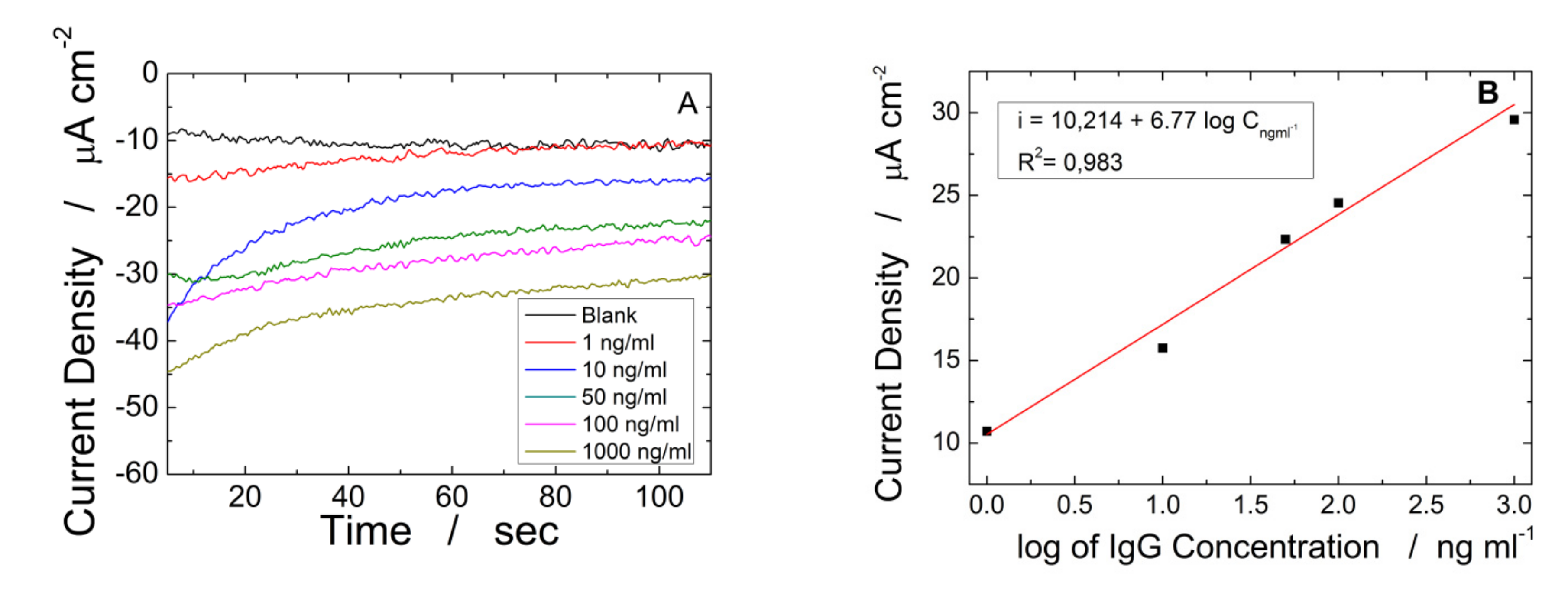
| ITO-ZnO NRs-rGO | CH Logarithmic | 10–1000 | 6.77 ∗ C−1 | 1.25 | 0.982 | This work |
Publisher’s Note: MDPI stays neutral with regard to jurisdictional claims in published maps and institutional affiliations. |
© 2022 by the authors. Licensee MDPI, Basel, Switzerland. This article is an open access article distributed under the terms and conditions of the Creative Commons Attribution (CC BY) license (https://creativecommons.org/licenses/by/4.0/).
Share and Cite
Patella, B.; Moukri, N.; Regalbuto, G.; Cipollina, C.; Pace, E.; Di Vincenzo, S.; Aiello, G.; O’Riordan, A.; Inguanta, R. Electrochemical Synthesis of Zinc Oxide Nanostructures on Flexible Substrate and Application as an Electrochemical Immunoglobulin-G Immunosensor. Materials 2022, 15, 713. https://doi.org/10.3390/ma15030713
Patella B, Moukri N, Regalbuto G, Cipollina C, Pace E, Di Vincenzo S, Aiello G, O’Riordan A, Inguanta R. Electrochemical Synthesis of Zinc Oxide Nanostructures on Flexible Substrate and Application as an Electrochemical Immunoglobulin-G Immunosensor. Materials. 2022; 15(3):713. https://doi.org/10.3390/ma15030713
Chicago/Turabian StylePatella, Bernardo, Nadia Moukri, Gaia Regalbuto, Chiara Cipollina, Elisabetta Pace, Serena Di Vincenzo, Giuseppe Aiello, Alan O’Riordan, and Rosalinda Inguanta. 2022. "Electrochemical Synthesis of Zinc Oxide Nanostructures on Flexible Substrate and Application as an Electrochemical Immunoglobulin-G Immunosensor" Materials 15, no. 3: 713. https://doi.org/10.3390/ma15030713
APA StylePatella, B., Moukri, N., Regalbuto, G., Cipollina, C., Pace, E., Di Vincenzo, S., Aiello, G., O’Riordan, A., & Inguanta, R. (2022). Electrochemical Synthesis of Zinc Oxide Nanostructures on Flexible Substrate and Application as an Electrochemical Immunoglobulin-G Immunosensor. Materials, 15(3), 713. https://doi.org/10.3390/ma15030713