Article

Fabrication of CuYO2 Nanofibers by Electrospinning and Applied to Hydrogen Harvest

1
Department of Materials and Mineral Resources Engineering, National Taipei University of Technology, No. 1, Section 3, Zhongxiao E. Rd., Taipei 106, Taiwan
2
Institute of Materials Science and Engineering, National Taipei University of Technology, No. 1, Section 3, Chung-Hsiao East Road, Taipei 106, Taiwan
3
School of Dental Technology, Taipei Medical University, 250, Wu-Hsing Street, Taipei 110, Taiwan
4
SRICT-Institute of Science and Research, UPL University of Sustainable Technology, Block No. 402, Ankleshwar-Valia, Rd., Vataria, Ankleshwar 393135, Gujarat, India
5
E-Current Co., Ltd., 10F.-5, No. 50, Sec. 4, Nanjing E. Rd., Songshan Dist., Taipei 10553, Taiwan
*
Authors to whom correspondence should be addressed.
Materials 2022, 15(24), 8957; https://doi.org/10.3390/ma15248957
Submission received: 8 November 2022 / Revised: 6 December 2022 / Accepted: 9 December 2022 / Published: 15 December 2022
(This article belongs to the Special Issue Recent Progresses in Thermoelectric Materials)

Abstract

:
Hydrogen can be employed as an alternative renewable energy source in response to climate change, global warming, and the energy problem. Methanol gas steam reforming (SRM) is the major method used in industry to produce hydrogen. In the SRM process, the catalyst nature offers benefits such as low cost, simplicity, and quickness. In this work, delafossite copper yttrium oxide (CuYO2) nanofibers were successfully prepared by electrospinning. The prepared CuYO2 nanofibers have different physical and chemical properties including thermoelectric behavior. The electrospinning method was used to produce as-spun fibers and annealed in an air atmosphere to form Cu2Y2O5 fibers; then, Cu2Y2O5 fibers were annealed in a nitrogen atmosphere to form CuYO2 nanofibers. X-ray diffraction studies and thermogravimetric and transmission electron microscope analysis confirmed the formation of CuYO2 nanofibers. The CuYO2 nanofibers were applied to methanol steam reforming for hydrogen production to confirm their catalytic ability. The CuYO2 nanofibers exhibited high catalytic activity and the best hydrogen production rate of 1967.89 mL min−1 g-cat−1 at 500 °C. The highly specific surface area of CuYO2 nanofibers used in steam reforming reactions could have significant economic and industrial implications. The performance of these CuYO2 nanofibers in hydrogen generation could be very important in industries with a global economic impact. Furthermore, the H2 production performance increases at higher reaction temperatures.

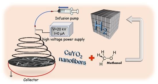
Graphical Abstract

1. Introduction

Delafossite oxides of CuIMIIIO2 (M = (Al, Ga, Fe, Cr, Y …)) have a combination of the monovalent metal CuI and the trivalent metal MIII. The structural component of delafossite is CuI and MO6 octahedron layers along the c axis. The upper and bottom oxygen of the MO6 octahedron is linearly coordinated to two CuI atoms [1,2,3,4]. The majority of research on optoelectronic properties, such as transparent semiconductors, dye-sensitized solar cells, thermoelectric properties, photo electrodes, luminescence, photo-catalysis, antibacterial, gas sensing, energy storage, and superconductivity properties, are also focused on delafossite materials based on their structural characteristics [5].
Copper complexes have been regarded as multifunctional materials because of their widespread industrial use as a chemical reaction catalyst for hydrogen synthesis, dehydrogenation, oxidation, and alkylation [6,7,8]. Copper yttrium oxide (CuYO2) nanofiber is a Cu-based delafossite that is now being studied because of its appealing physical characteristics for the aforementioned uses [9]. According to reports, the delafossite structure of CuYO2 has a p-type and wide-bandgap with a high See-beck coefficient of the semiconductor (+274 VK−1). The physical properties of CuYO2 in the a–b plane is compared to the c-axis direction. This suggests that the thermoelectric properties are fairly high. These CuYO2 metal oxide compounds are a good contender for high-temperature thermoelectric applications in air [10]. CuYO2 powder consistently exhibits excellent catalytic efficiency in a variety of reactions, including methanol steam reforming (MSR) and water–gas conversion [11].
This study applies the delafossite structure of a catalyst to methanol steam reforming for hydrogen production. CuYO2 nanofibers were synthesized as a catalyst. Sun et al. have reported that Y2O3 is helpful for alcohol dehydrogenation, as CuYO2 is reduced to Cu+Y2O3 after MSR, which was chosen for better catalytic effectiveness. Due to the reaction principle of the fixed-bed reactor, the solid catalyst or solid reactant is typically in the form of particles, and the fluid reacts by stacking in a bed of a certain thickness [12].
The electrospinning method creates fibers by stretching a liquid in an electric field using the self-repulsion effect. It causes an electrostatic charge on a precursor material. The electrospinning parameters, such as applied voltage, viscosity, and weight, have a significant impact on the morphology of the resulting fibers and can be adjusted for the desired application [13]. The electrospinning method creates nanofibers with a high specific surface area, as the electrospun fiber diameters range from tens of nanometers to a few micrometers. This method has been effectively applied for preparing polymer-based nano or microfibers in recent years. Electrospinning technology has numerous applications in energy and environmental sciences. In addition, metal oxide electrospun nanofibers have been used extensively in photovoltaics, sensor technology, catalysis, medicine, fuel cells, hydrogen storage, and supercapacitors [14,15,16].
Alternative sources of energy have been considered to address climate change and the limited supply of fossil fuels. In the fuel cell, hydrogen (H2) burns cleanly and produces no environmental pollutants, unlike the burning of fossil fuels [17,18]. Hydrogen fuel cell applications are a promising technology. In addition, H2 has the highest energy density per unit weight as compared with other fuels (i.e., 120.7 kJ g−1) [19,20]. Nowadays, steam reforming is the primary method used to create industrial hydrogen. Methanol can be reformed at a lower temperature, with a higher H2/C ratio than ethanol. Additionally, methanol lacks a carbon-carbon bond, has low sulfur content (5 ppm), and produces less carbonaceous products. Typically, steam reforming of methanol (SRM), partial oxidation, and decomposition processes are used to make hydrogen from methanol. Because of a low reaction temperature, appropriate water miscibility, high ratio of hydrogen concentration, and low CO level of the SRM process, methanol has attracted a lot of attention as a means of manufacturing hydrogen. Furthermore, SRM is a straightforward, effective endothermic reaction, making it appropriate for use in fuel cell applications [21,22].
The three main processes for producing hydrogen from methanol are (1) partial oxidation, (2) decomposition, and (3) the MSR process. The partial oxidation process only produces 66% of the hydrogen needed for fuel cells and involves an exothermic reaction as well. The highly endothermic reaction and high CO content ratio of the breakdown conversion process make it unsuitable for fuel cell construction. Therefore, the MSR process, which has an endothermic reaction, has been used for hydrogen production, which requires a low reaction temperature to achieve a high hydrogen concentration ratio, a high hydrogen production rate of up to 75%, and a low CO level as a byproduct [23,24].
CH3OH → CO + 2H2 ΔH0 = 92.0 kJ/mol
CH3OH + H2O → CO2 + 3H2 ΔH0 = 49.5 kJ/mol
CH3OH + ½O2 → CO2 + 2H2 ΔH0 = −155 kJ/mol
In the MSR process, three reactions typically result in the production of hydrogen from methanol: (4) decomposition of methanol, (5) reformation of methanol steam, and (6) reaction of water gas shift (WGS), as shown below.
CH3OH → CO + 2H2
CH3OH + H2O → CO2 + 3H2
CO + H2O → CO2 + H2
Our research team focuses on the copper-based delafossite materials used in the study for maximum H2 production rate in the MSR process. We have previously prepared CuCr0.4Fe0.6O2, CuFeO2-CeO2, CuCrO2, CuFeO2 powder, and CuYO2 powder for application in the MSR process. We have learned from these catalyst studies that the surface area and catalytic activity of copper-based delafossite materials are crucial to the MSR process and contribute to its high production rate more than other catalysts do [25,26,27].
In this study, the electrospinning method was employed to create the CuYO2 nanofiber catalyst, which was then used for MSR. The CuYO2 nanofibers created thus far have a delafossite crystal structure. For Cu+ ions involved in d–d transitions, the CuYO2 fiber demonstrates higher hydrogen generation. It also exhibits a Cu+ inter-configuration transition from 3d94s1 to 3d10. Additionally, in linear coordination, Y3+ ions share edges with Cu+ ions at the CuYO2 octahedral sites. One of the primary reasons why these catalysts are used in the study of hydrogen energy is that the CuYO2 nanofiber catalyst has intercalating anionic species [28,29]. During the MSR process, the CuYO2 nanofiber exhibited a high rate of hydrogen production and a low rate of coke formation. Additionally, the ability of the CuYO2 nanofiber to produce hydrogen at a higher rate than CuFeO2 nanopowder, CuCrO2 nanopowder, CuCrO2 bulk powder, and commercial catalysts (Cu/Al/Zn) at various temperatures will be evaluated.

2. Materials and Methods

2.1. Materials and Instrumentation

Copper nitrate (99% purity), Yttrium nitrate (99.8% purity), and N, N-dimethylformamide (99.8% purity) were purchased from Aldrich AVATOR chemical company, Taipei, Taiwan. Polyvinyl pyrrolidone (PVP, Mw = 1,300,000) and ethanol were obtained from Echo Chemical Co., Ltd., Miaoli, Taiwan. The material structural properties were identified with a transmission electron microscope (TEM, JEM-2100F, JEOL, Tokyo, Japan). The crystal structure arrangements were characterized with an X-ray diffractometer (XRD) (D2 Phaser, Bruker, Billerica, MA, USA). Field emission scanning electron microscopy (FE-SEM) studies were performed with a JEOL JSM-7610F, Tokyo, Japan. A gas chromatograph (GC 1000, China Chromatography, New Taipei City, Taiwan) with one column (60/80 Carboxen® 1000, SUPER CHROMA ENTERPRISE LTD., Taipei, Taiwan) for H2 (7′ × 1/16″ in, stainless steel) was used to measure hydrogen production performance. The thermal decomposition behavior of electrospun fibers was studied by thermogravimetric analysis/differential scanning calorimeter (TGA/DSC, STA 449 F5, NETZSCH, Selb, Germany). The surface area of the CuYO2 nanofibers was calculated with a Brunauer-Emmett-Teller (BET) surface area analyzer (TriStar II 3030, Micromeritics Instrument Corporation, Norcross, GA, USA). The adsorbate in the BET surface area studies was high-purity nitrogen gas, and the N2 gas volume was measured using P/P0 = 0–0.3 at various pressures. The CuCrO2-CeO2 nanopowders were degassed before BET studies by purging with N2 at 150 °C for 12 h.

2.2. Preparation of Cu2Y2O5 Nanofibers

The electrospinning precursor was prepared by dissolving 0.548 g of copper nitrate and 0.827 g of yttrium nitrate in 14.4 mL of N, N-dimethylformamide. Then, 2.2 g of polyvinylpyrrolidone (PVP, Mw = 1,300,000) were dissolved in the solution. After 6 h of stirring, an ocean-green, viscous, gel-like precursor solution was obtained. A horizontal syringe pump was loaded with the Al2O3 precursor solution. Standard electrospinning setups have a high-voltage source connected to a metallic needle, which is connected to a syringe pump. In this study, the syringe pump was connected to a Teflon tube (125 mm in length and 4.2 mm in diameter). The precursor solution was placed in a 10 mL syringe fitted with a 0.5 mm stainless steel needle during the electrospinning process. A voltage of 20 kV was applied to the stainless steel needle tip, and the collector was placed 15 cm away from the needle tip, with the flow set to 0.02 mL/h and temperature maintained at 40 °C. For the formation of Al2O3 precursor fibers, the electrospun Al2O3 precursor was distributed uniformly over the collector. Additionally, humidity was controlled below 20% to obtain the as-spun fiber. The as-spun fiber was annealed at 800 °C at a heating rate of 10 °C/min to remove the PVP contained in the as-spun fiber and to synthesize the copper and yttrium into Cu2Y2O5 to facilitate the formation of subsequent CuYO2 nanofibers. The prepared Cu2Y2O5 and CuYO2 nanofibers were analyzed by TGA, XRD, SEM, TEM, and BET characterization studies.

2.3. Methanol Steam Reforming

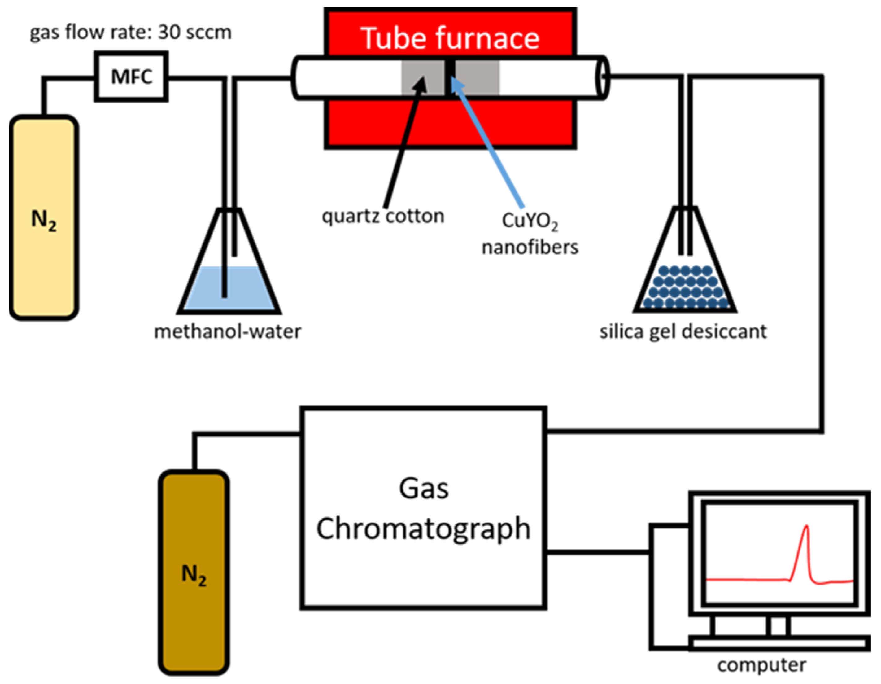
The methanol steam reforming process was executed in a tube flow reactor which was performed with China Chromatography, New Taipei City, Taiwan. The experiment used a quartz tube with an inside diameter of 1.2 cm and a length of 25 cm as a tube flow reactor for the catalytic reaction. For this, 20 mg of CuYO2 nanofibers were sandwiched between the quartz cotton in the middle of the quartz tube and then heated to 250, 300, 350, 400, 450, and 500 °C. Methanol and water were uniformly mixed at a molar ratio of 3:1 to prepare a methanol–water mixture, and that mixture was heated to 80 °C on a hot plate to generate methanol–water vapor by evaporation. Nitrogen was introduced as the carrier gas at a flow rate of 30 sccm. The system was connected to a gas chromatograph, which was used to analyze the gas produced at each temperature for later averaging (Scheme 1).

3. Results and Analysis

3.1. TGA Analysis of Cu2Y2O5 Nanofibers

To observe the decomposition mechanism of the as-spun fibers at high temperatures, a simultaneous thermogravimetric analyzer was used to observe their TGA/DSC curves, and the temperature of the air atmosphere was increased to 800 °C at a heating rate of 10 °C/min. The TGA/DSC curves of electrospun Cu2Y2O5 nanofibers are shown in Figure 1. The weight loss before 100 °C was due to the volatilization of the remaining water in the sample. The slight weight loss and exothermic slope at approximately 150 °C were due to DMF decomposition. The endothermic slope at 265 °C indicated the decomposition of copper nitrate to form CuO. From 250 °C to 520 °C, a large amount of heat was generated and the weight was greatly reduced by 85%, which occurred due to the decomposition of PVP. During this decomposition, the endothermic trend at about 340 °C indicated the complete removal of water by Cu2Y2O5 nanofibers. The endothermic change at around 360 °C represented the decomposition of yttrium nitrate to form Y2O3. The endothermic slope at 700 °C indicated the combination of Y2O3 and CuO to form Cu2Y2O5.

3.2. XRD Analysis of Cu2Y2O5 Nanofibers and CuYO2 Nanofibers

The XRD pattern of Cu2Y2O5 nanofibers is shown in Figure 2. After the as-spun fibers were annealed at high temperatures, the copper nitrate and yttrium nitrate decomposed and formed copper yttrium oxide. According to JCPDS card (Joint Committee on Powder Diffraction Standards) PDF#81-0703, pure Cu2Y2O5 is an orthorhombic phase. The orthorhombic Cu2Y2O5 is a minor phase in the mixture of cubic Y2O3 and CuO. The XRD pattern of CuYO2 nanofibers is shown in Figure 3. After Cu2Y2O5 fibers were annealed at 780 °C in a nitrogen atmosphere, the Cu2Y2O5 was deoxygenated to form CuYO2. According to JCPDS cards PDF#39-0244 and PDF#37-0930, CuYO2 is composed of rhombohedral and hexagonal phases, respectively.

3.3. FESEM and TEM Analyses of Cu2Y2O5 Nanofibers

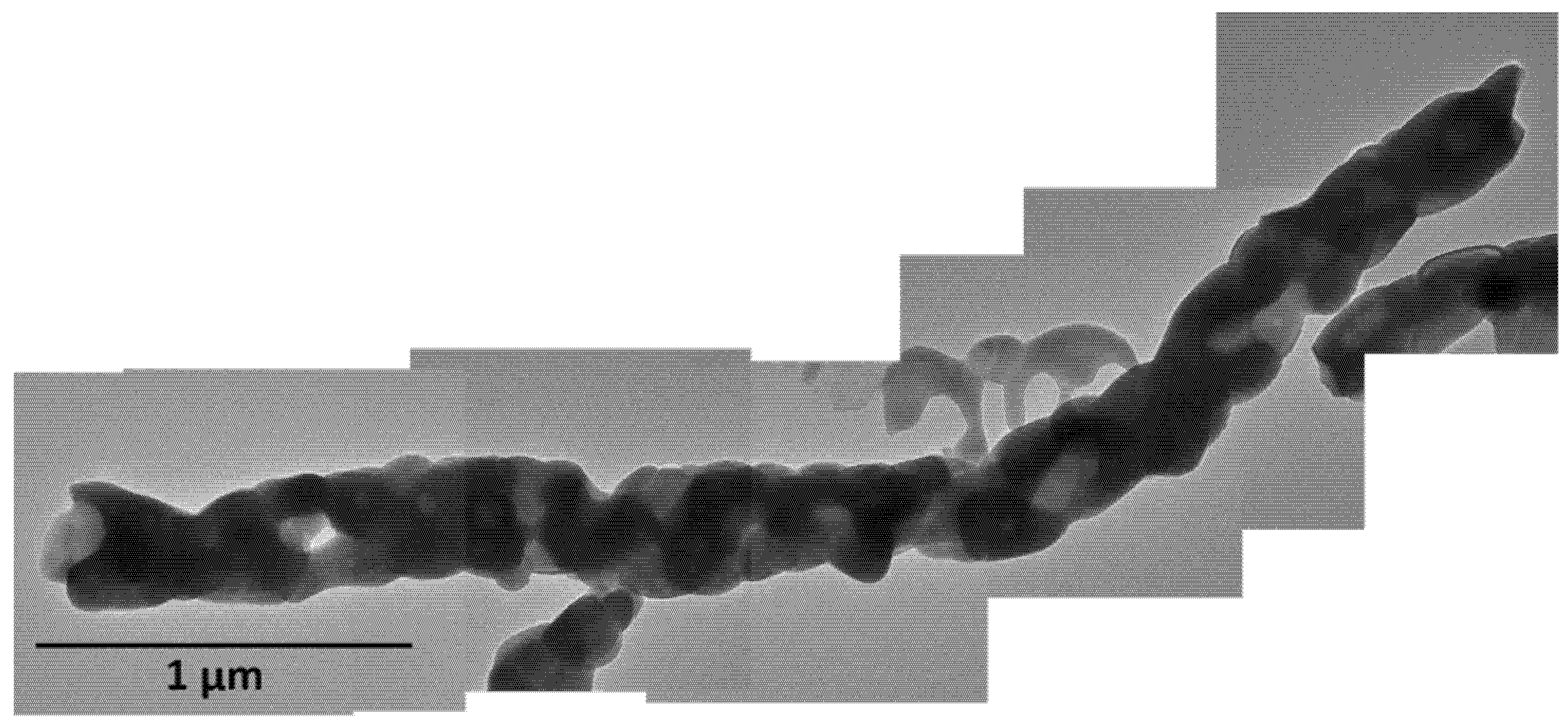
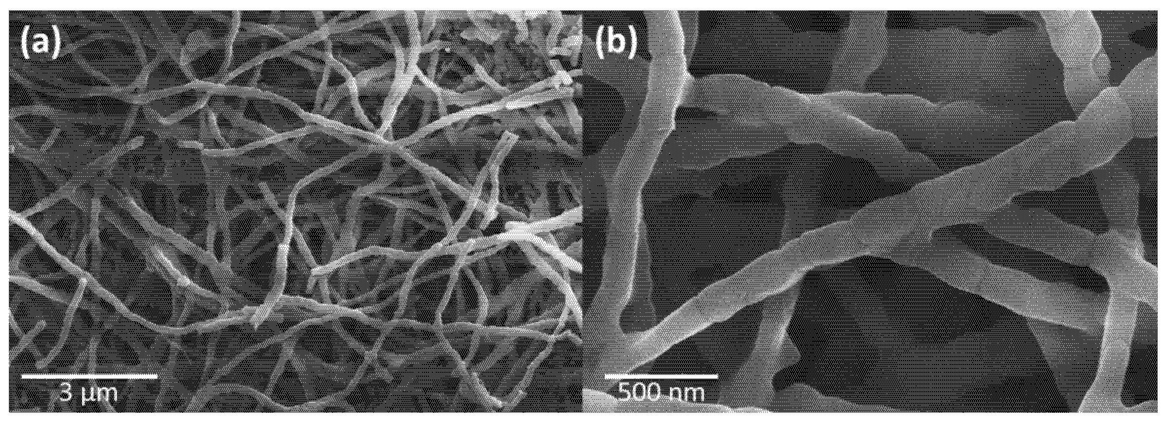
Figure 4a,b shows the FESEM image of the Cu2Y2O5 nanofibers. Based on PVP, the average fiber diameter was about 950 ± 27.6 nm. The morphology of the as-spun fibers after they were annealed in air at a heating rate of 10 °C/min to 800 °C formed Cu2Y2O5 nanofibers. In the FESEM image, it could be observed that the surfaces of the Cu2Y2O5 nanofibers were rugged and composed of crystalline particles. Furthermore, the PVP disappeared and the diameters decreased to about 243 ± 22.5 nm because of the high temperature. A TEM image of the Cu2Y2O5 nanofibers is shown in Figure 5. It can be observed from the TEM image that the nanofibers were composed of a series of crystal grains and were about 237 ± 16.9 nm in diameter.

3.4. FESEM and TEM Analysis of CuYO2 Nanofibers

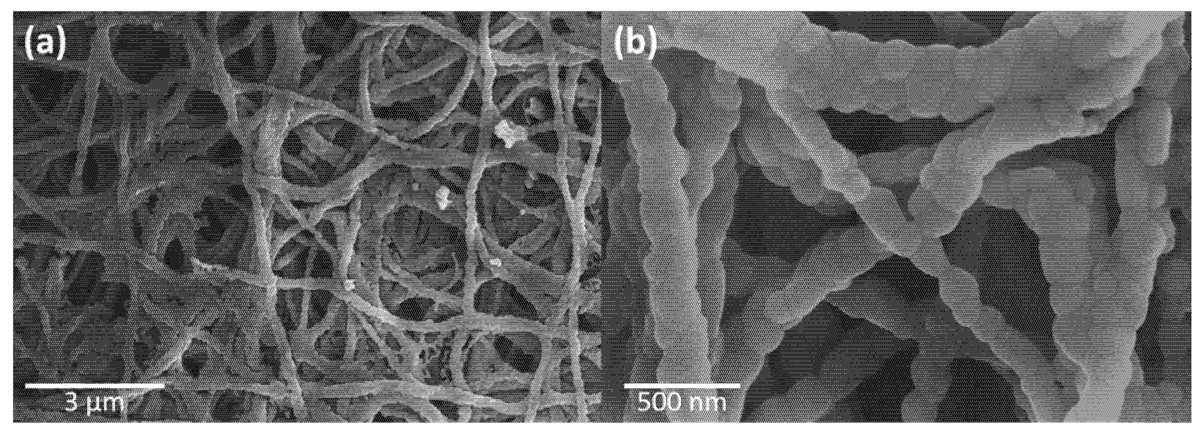
Figure 6a,b presents the FESEM images of CuYO2 nanofibers. After Cu2Y2O5 nanofibers were heated at 10 °C/min to 780 degrees and annealed at that temperature for 30 min in a nitrogen atmosphere, they were deoxidized to form CuYO2 nanofibers. In the FESEM images, it can be observed that the surfaces of CuYO2 nanofibers were smoother than those of Cu2Y2O5 nanofibers.
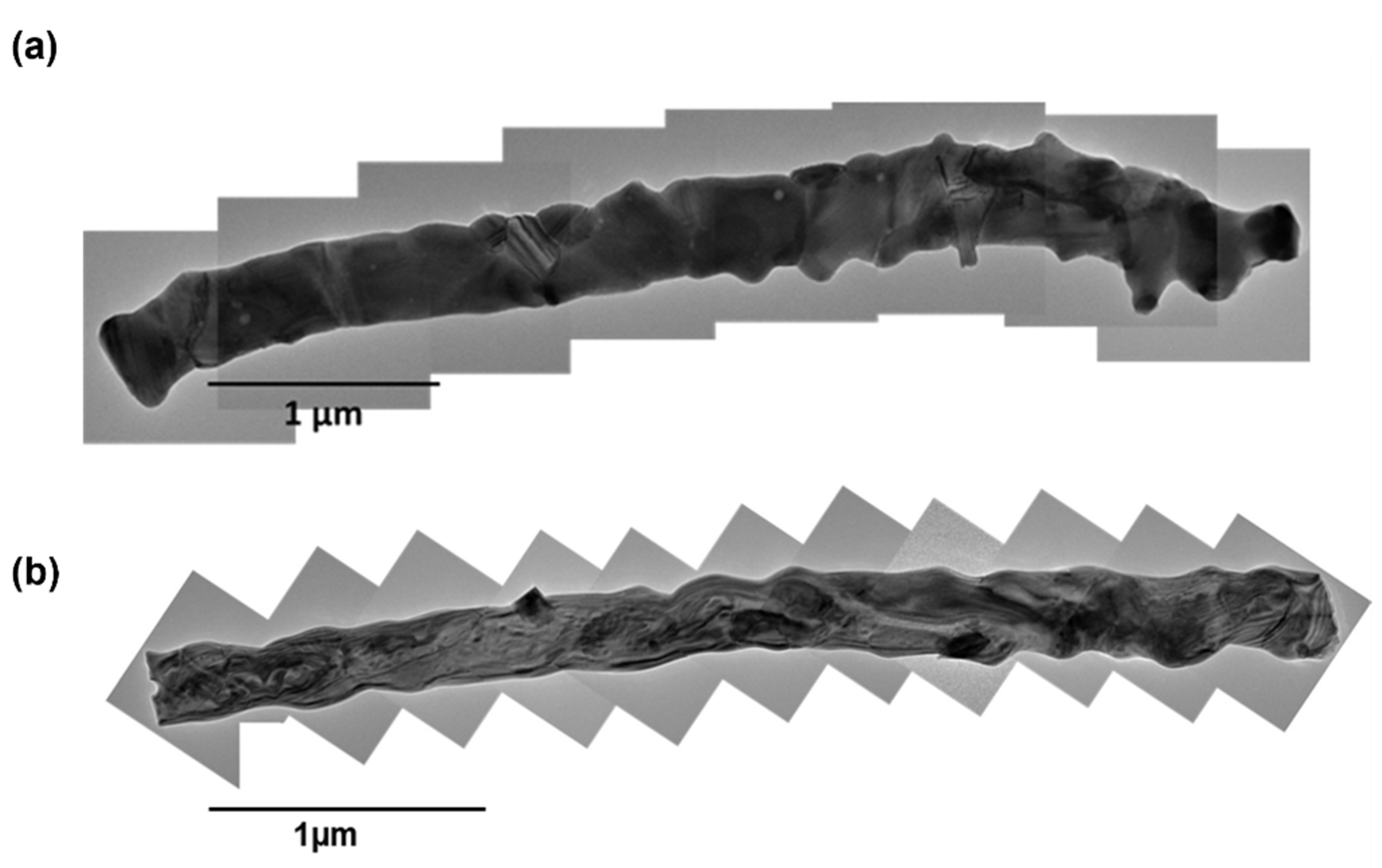
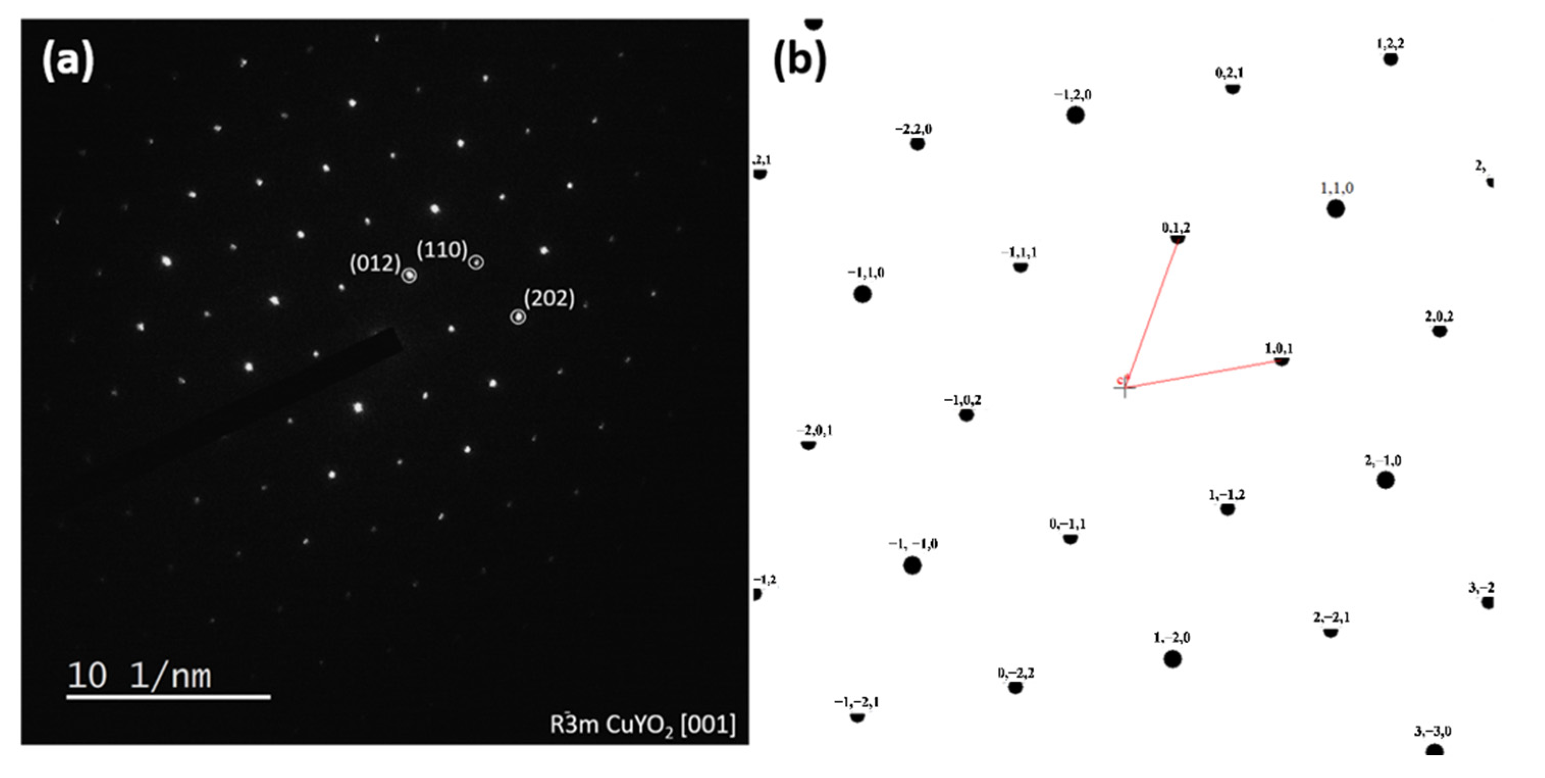
Figure 7a shows a TEM image of an R 3 ¯ m CuYO2 nanofiber, and Figure 7b shows a TEM image of a P63/MMC CuYO2 nanofiber. It can be observed from the TEM image that the nanofiber was composed of a series of crystal grains, and the diameter was fixed at 220 ± 17.4 nm. The TEM image SAED patterns are shown in Figure 8a and Figure 9a. The SAED pattern was used to confirm that the nanofibers were composed of CuYO2 in two different space groups. From the TEM image, it can be observed that Cu2Y2O5 nanofibers grains merged after annealing to form CuYO2 nanofibers. The CuYO2 nanofiber grains in the R 3 ¯ m space group were arranged in a nodular structure, whereas the those in the P63/mmc space group had no obvious grain boundaries. The simulated diffraction pattern of R 3 ¯ m CuYO2 nanofibers is shown in Figure 8b, and the simulated diffraction pattern of P63/mmc CuYO2 nanofibers is shown in Figure 9b. Both diffraction patterns confirmed that the d-spacing was consistent with the diffraction patterns of CuYO2 nanofibers in the R 3 ¯ m (The Inorganic Crystal Structure Database, ICSD ID: 60848) and P63/mmc (ICSD ID: 35580) space groups simulated in CaRIne.

3.5. Specific Surface Area Analysis of CuYO2 Nanofibers

The specific surface areas of the CuYO2 nanofibers are listed in Table 1. Table 1 shows the specific surface areas of the different delafossite complexes prepared by glycine-nitrate combustion, solid-state reaction, and electrospinning. The specific surface area of the CuYO2 nanofibers produced in this experiment was 10.22 m2/g, which is much larger than the specific surface areas of solid-state reactions and other electrospinning products.

3.6. Methanol Steam Reforming Performance

The H2 production rate with the CuYO2 nanofiber catalyst was determined using a gas chromatograph equipped with a thermal conductivity detector. At 250–500 °C, the hydrogen efficiency and productivity at a flow rate of 30 sccm were measured and converted to milliliters per minute (mL STP per min per g-cat) (Figure 10). The temperature of the methanol and water was 80 °C, and the methanol-to-water ratio was 1:4 due to the vapor pressure difference. To maximize yield, the CuYO2 nanofiber catalyst powder was activated for 10 min at each temperature without the methanol steam. Then the carrier gas was activated to fill the system with methanol steam, and the hydrogen production performance was measured at the gas outlet pipe. The H2 production performances and H2 production rates were also calculated with the following Equations (7) and (8) [35,36].
Methanol   conversion   ( % ) = methanol   in   methanol   out methanol   in   ×   100
Hydrogen   production   rate = Hydrogen   % .   mL . 30   mL / min cm 3 · g  
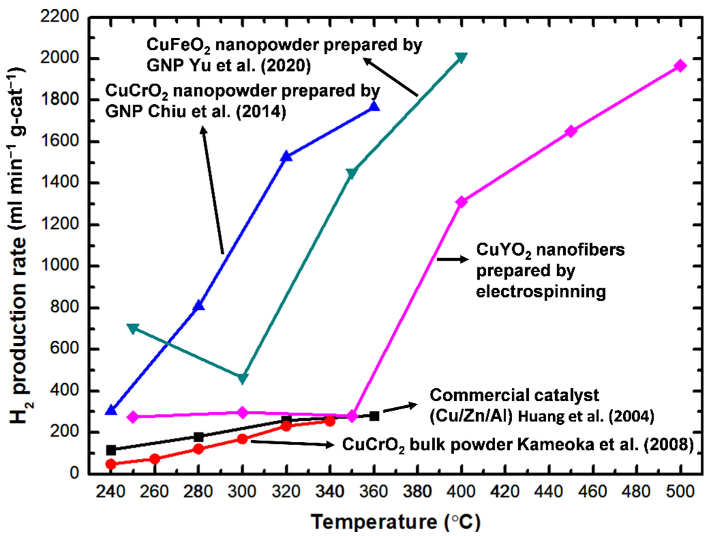
Figure 11 depicts the relationship between the rate of H2 production and the reaction temperature in the methanol steam reforming process using the CuYO2 nanofiber catalyst. At 400 °C, the maximum hydrogen production rate was 1967.89 mL min−1 g-cat−1. Table 2 shows the hydrogen production rate of CuYO2 nanofibers at different temperatures. The data show that, when the temperature rose, the rate of hydrogen production increased as well. However, when the temperature was too high, the catalyst reached its activity more quickly, and the experiment was not continued at higher temperatures. Figure 11 shows that the electrospun CuYO2 nanofibers had much higher hydrogen production efficiency than those of the commercial Cu/Al/Zn catalyst, CuCrO2 bulk catalyst, CuFeO2 (GNP), CuCrO2 (GNP), and CuCrO2 (solid-state method) [27,29,37,38]. In addition, the H2-activated catalyst is typically dangerous in air because of its high activity and potential for ignition and explosion. In contrast, CuYO2 nanofibers are extremely stable in the air. As a result, there is no need for high-temperature activation treatment of the CuYO2 nanofiber catalyst for the SRM process. This finding implies that, if CuYO2 nanofibers are used in fuel cell vehicles, they can achieve higher efficiency than conventional catalysts. The catalyst stability, SRM conditions, and reactor conditions will be optimized and tested in future work.

3.7. XRD and SEM Analysis of CuYO2 Nanofibers after MSR

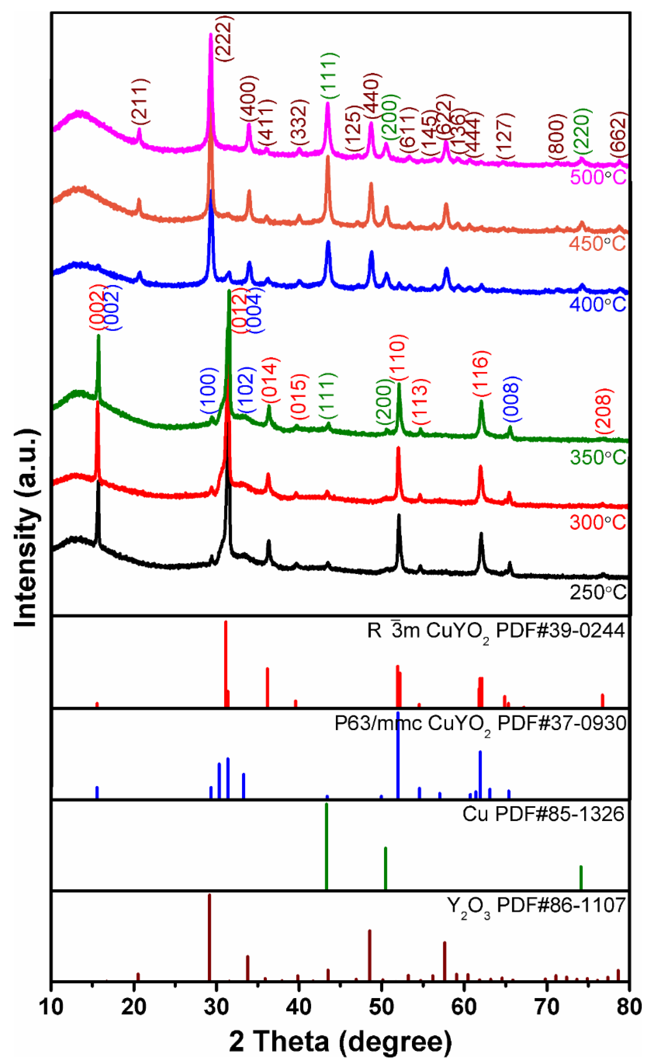
Figure 12 shows the XRD pattern of CuYO2 nanofibers after MSR at different temperatures (250–500 °C). From the XRD pattern, it was observed that the CuYO2 in the R 3 ¯ m and P63/MMC space groups still maintained a catalytic temperature between 250 °C and 350 °C. After the SRM process, the peaks of the copper (111), (200), and (220) planes could be observed at 2θ = 43.316°, 50.448°, and 74.124° (PDF#85-1326), respectively, caused by the precipitation of CuYO2. When the catalytic temperature rose above 400 °C, the peak of CuYO2 gradually disappeared and Y2O3 (PDF#86-1107) began to precipitate. Finally, when the catalytic temperature reached 500 °C, the CuYO2 nanofibers almost completely disappeared. In this form, CuYO2 nanofibers become the Cu/Y2O3 phase, increasing both the catalytic activity of Cu and the hydrogen production performance.
Figure 13a–f shows SEM images of CuYO2 after MSR at different temperatures. As shown in Figure 13a–c, a few precipitates formed on the surfaces of CuYO2 nanofibers after catalysis at a lower temperature. Figure 13d–f illustrates that when the catalytic temperature reached 400 °C, precipitate particles formed on the surfaces of fibers, but these particles did not affect the catalytic activity.

4. Conclusions

In this work, Cu2Y2O5 and CuYO2 nanofiber catalysts were successfully prepared by electrospinning and applied to the methanol steam reforming process (SRM). The CuYO2 nanofibers were studied by scanning electron microscopy, transmission electron microscopy, X-ray diffractometric, Thermogravimetric analysis, and Burner Emmett-Teller analysis. The diameter of the CuYO2 nanofibers was fixed at 220 ± 17.4 nm and the specific surface area was 10.22 m2/g. In the SRM process, the CuYO2 nanofiber catalyst exhibited the best hydrogen production rate of 1967.89 mL min−1 g-cat−1 at a reaction temperature of 500 °C. Furthermore, under the same operating conditions, the hydrogen generation rate of CuYO2 nanofibers was compared with those of previously-reported catalysts. A higher rate of hydrogen production was achieved because of the higher catalytic activity and larger surface area of the CuYO2 nanofibers. The catalyst stability and reactor parameters have also been optimized. Based on the H2 production performance, the CuYO2 nanofibers are appropriate for use as a catalyst for industrial H2 production and fuel cell applications in automobiles.

Author Contributions

Conceptualization, K.-C.H., S.S. and C.-L.Y.; software, K.-C.H. and S.S.; validation, K.-C.H., A.K.K., S.S. and C.-L.Y.; formal analysis, K.-C.H., A.K.K. and C.-L.Y.; investigation, K.-C.H., A.K.K., S.S. and C.-L.Y.; resources, K.-C.H., A.K.K., C.-L.Y. and T.-W.C.; data curation, C.-W.H., F.-Y.F., K.N., P.-C.C. and Y.-K.S.; writing—original draft preparation, K.-C.H., S.S., C.-L.Y., T.-W.C., C.-W.H., F.-Y.F., K.N., P.-C.C. and Y.-K.S.; visualization, K.-C.H., S.S., C.-L.Y., T.-W.C., C.-W.H., F.-Y.F. and Y.-K.S.; supervision, T.-W.C.; project administration, T.-W.C.; funding acquisition, T.-W.C. All authors have read and agreed to the published version of the manuscript.

Funding

This work was supported by the Ministry of Science and Technology of Taiwan (MOST 108-2221-E-027-056, MOST 109-2221-E-027-068, MOST 109-2221-E-027-059, MOST 110-2221-E-027-041, MOST-110-2221-E-027-041-and MOST 109-2113-M-027-001-MY3). This work was supported by the National Science and Technology Council of Taiwan (NSTC 111-2221-E-027-104). The authors appreciate the Precision Research and Analysis Centre of the National Taipei University of Technology (NTUT) for providing the measurement facilities.

Institutional Review Board Statement

Not applicable.

Informed Consent Statement

Not applicable.

Data Availability Statement

Not applicable.

Conflicts of Interest

The authors declare no conflict of interest.

References

  1. Nishio, K.; Okada, T.; Kikuchi, N.; Mikusu, S.; Iida, T.; Tokiwa, K.; Watanabe, T.; Kineri, T. Preparation of Delafossite CuYO2 by Metal-citric Acid Complex Decomposition Method. MRS Proc. 2009, 1166, 1166-N03-13. [Google Scholar] [CrossRef]
  2. Sinnarasa, I.; Thimont, Y.; Presmanes, L.; Barnabe, A.; Tailhades, P. Thermoelectric and Transport Properties of Delafossite CuCrO2:Mg Thin Films Prepared by RF Magnetron Sputtering. Nanomaterials 2017, 7, 157. [Google Scholar] [CrossRef] [PubMed] [Green Version]
  3. Sanam, P.J.; Shah, M.; Pradyumnan, P. Structure induced modification on thermoelectric and optical properties by Mg doping in CuCrO2 nanocrystals. Solid State Commun. 2022, 353, 114855. [Google Scholar] [CrossRef]
  4. Barnabé, A.; Thimont, Y.; Lalanne, M.; Presmanes, L.; Tailhades, P. p-Type conducting transparent characteristics of delafossite Mg-doped CuCrO2 thin films prepared by RF-sputtering. J. Mater. Chem. C 2015, 3, 6012–6024. [Google Scholar] [CrossRef] [Green Version]
  5. Sakthinathan, S.; Rajakumaran, R.; Keyan, A.K.; Yu, C.-L.; Wu, C.-F.; Vinothini, S.; Chen, S.-M.; Chiu, T.-W. Novel construction of carbon nanofiber/CuCrO2 composite for selective determination of 4-nitrophenol in environmental samples and for supercapacitor application. RSC Adv. 2021, 11, 15856–15870. [Google Scholar] [CrossRef]
  6. Sakthinathan, S.; Rajakumaran, R.; Keyan, A.K.; Vasu, D.; Chen, S.M.; Chiu, T.W. Synthesis of B-RGO-MWCNT/CuFeO2 Composite for Efficient Hydrogen Evolution Reaction. ECS J. Solid State Sci. Technol. 2021, 10, 111001. [Google Scholar] [CrossRef]
  7. Manoj, R.; Nisha, M.; Vanaja, K.A.; Jayaraj, M.K. Effect of oxygen intercalation on properties of sputtered CuYO2 for potential use as p-type transparent conducting films. Bull. Mater. Sci. 2008, 31, 49–53. [Google Scholar] [CrossRef] [Green Version]
  8. Trari, M.; Bouguelia, A.; Bessekhouad, Y. p-Type CuYO2 as hydrogen photocathode. Sol. Energy Mater. Sol. Cells 2006, 90, 190–202. [Google Scholar] [CrossRef]
  9. Ehara, T. Preparation of CuYO2 Thin Films by Sol-Gel Method Using Copper Acetate and Yttrium Acetate as Metal Sources. J. Mater. Sci. Chem. Eng. 2016, 4, 24–28. [Google Scholar]
  10. Tsuboi, N.; Ohara, H.; Hoshino, T.; Kobayashi, S.; Kato, K.; Kaneko, F. Luminescence Properties of Delafossite-Type CuYO2 Doped with Calcium, Oxygen or Rare Earth Tb. Jpn. J. Appl. Phys. 2005, 44, 765–768. [Google Scholar] [CrossRef]
  11. Yu, C.-L.; Sakthinathan, S.; Chen, S.-Y.; Yu, B.-S.; Chiu, T.-W.; Dong, C. Hydrogen generation by methanol steam reforming process by delafossite-type CuYO2 nanopowder catalyst. Microporous Mesoporous Mater. 2021, 324, 111305. [Google Scholar] [CrossRef]
  12. Sun, J.; Qiu, X.-P.; Wu, F.; Zhu, W.-T. H2 from steam reforming of ethanol at low temperature over Ni/Y2O3, Ni/La2O3 and Ni/Al2O3 catalysts for fuel-cell application. Int. J. Hydrogen Energy 2005, 30, 437–445. [Google Scholar] [CrossRef]
  13. Xue, J.; Xie, J.; Liu, W.; Xia, Y. Electrospun Nanofibers: New Concepts, Materials, and Applications. Acc. Chem. Res. 2017, 50, 1976–1987. [Google Scholar] [CrossRef]
  14. Lei, Y.; Wang, Q.; Peng, S.; Ramakrishna, S.; Zhang, D.; Zhou, K. Electrospun Inorganic Nanofibers for Oxygen Electrocatalysis: Design, Fabrication, and Progress. Adv. Energy Mater. 2020, 10, 1902115. [Google Scholar] [CrossRef]
  15. Locarno, S.; Eleta-Lopez, A.; Lupo, M.G.; Gelmi, M.L.; Clerici, F.; Bittner, A.M. Electrospinning of pyrazole-isothiazole derivatives: Nanofibers from small molecules. RSC Adv. 2019, 9, 20565–20572. [Google Scholar] [CrossRef] [PubMed] [Green Version]
  16. Chao, T.-C.; Sakthinathan, S.; Chiu, T.-W.; Fu, Y. Anisotropic delafossite-type CuFeO2 thin films deposited by electrospinning with rotating collector. J. Ceram. Soc. Jpn. 2019, 127, 498–503. [Google Scholar] [CrossRef] [Green Version]
  17. Yu, C.-L.; Lai, G.-T.; Sakthinathan, S.; Lin, C.-C.; Chiu, T.-W.; Liu, M.-C. Hydrogen generation from methanol steam reforming process of CuCrO2-CeO2 nanopowders catalyst. Mater. Sci. Eng. B 2022, 286, 115989. [Google Scholar] [CrossRef]
  18. Huang, R.J.; Sakthinathan, S.; Chiu, T.W.; Dong, C. Hydrothermal synthesis of high surface area CuCrO2 for H2 production by methanol steam reforming. RSC Adv. 2021, 11, 12607–12613. [Google Scholar] [CrossRef]
  19. Yu, C.L.; Sakthinathan, S.; Lai, G.T.; Lin, C.C.; Chiu, T.W.; Liu, M.C. ZnO-ZnCr2O4 composite prepared by a glycine nitrate process method and applied for hydrogen production by steam reforming of methanol. RSC Adv. 2022, 12, 22097–22107. [Google Scholar] [CrossRef]
  20. Abdi, A.; Bagtache, R.; Trari, M. Physical and photo-electrochemical properties of oxygen-rich delafossite CuYO2. J. Solid State Electrochem. 2018, 22, 3191–3196. [Google Scholar] [CrossRef]
  21. Younsi, M.; Saadi, S.; Bouguelia, A.; Aider, A.; Trari, M. Synthesis and characterization of oxygen-rich delafossite CuYO2+x—Application to H2-photo production. Sol. Energy Mater. Sol. Cells 2007, 91, 1102–1109. [Google Scholar] [CrossRef]
  22. Schneller, T.; Waser, R.; Kosec, M.; Payne, D. Chemical Solution Deposition of Functional Oxide Thin Films; Springer: Vienna, Austria, 2013. [Google Scholar] [CrossRef]
  23. Papavasiliou, J.; Avgouropoulos, G.; Ioannides, T. Production of hydrogen via combined steam reforming of methanol over CuO-CeO2 catalysts. Catal. Commun. 2004, 5, 231–235. [Google Scholar] [CrossRef]
  24. Brown, J.; Gulari, E. Hydrogen production from methanol decomposition over Pt/Al2O3 and ceria promoted Pt/Al2O3 catalysts. Catal. Commun. 2004, 5, 431–436. [Google Scholar] [CrossRef]
  25. Poirier, M.G.; Sapundzhiev, C. Catalytic decomposition of natural gas to hydrogen for fuel cell applications. Int. J. Hydrogen Energy 1997, 22, 429–433. [Google Scholar] [CrossRef]
  26. Agrell, J.; Hasselbo, K.; Jansson, K.; Järås, S.G.; Boutonnet, M. Production of hydrogen by partial oxidation of methanol over Cu/ZnO catalysts prepared by microemulsion technique. Appl. Catal. A Gen. 2001, 211, 239–250. [Google Scholar] [CrossRef]
  27. Kameoka, S.; Tanabe, T.; Tsai, A.P. Self-assembled porous nano-composite with high catalytic performance by reduction of tetragonal spinel CuFe2O4. Appl. Catal. A Gen. 2010, 375, 163–171. [Google Scholar] [CrossRef]
  28. Pajaie, H.S. Hydrogen Production from Methanol Steam Reforming over Cu/ZnO/Al2O3/CeO2/ZrO2 Nanocatalyst in an Adiabatic Fixed-Bed Reactor. Iran. J. Energy Environ. 2012, 3, 307–313. [Google Scholar]
  29. Chiu, T.-W.; Hong, R.-T.; Yu, B.-S.; Huang, Y.-H.; Kameoka, S.; Tsai, A.-P. Improving steam-reforming performance by nanopowdering CuCrO2. Int. J. Hydrogen Energy 2014, 39, 14222–14226. [Google Scholar] [CrossRef]
  30. Chiu, T.-W.; Lu, Y.-S. Preparation of CuCr1-xFexO2 Delafossite Solid Solution Powder Via a Self-Combustion Glycine Nitrate Process. Ferroelectrics 2016, 491, 149–154. [Google Scholar] [CrossRef]
  31. Chiu, T.-W.; Huang, P.-S. Preparation of delafossite CuFeO2 coral-like powder using a self-combustion glycine nitrate process. Ceram. Int. 2013, 39, S575–S578. [Google Scholar] [CrossRef]
  32. Lalanne, M.; Barnabee, A.; Mathieu, F.; Tailhades, P. Synthesis and Thermostructural Studies of a CuFe1−xCrxO2 Delafossite Solid Solution with 0 ≤ x ≤ 1. Inorg. Chem. 2009, 48, 6065–6071. [Google Scholar] [CrossRef] [PubMed]
  33. Çetin, C.; Akyıldız, H. Production, and characterization of CuCrO2 nanofibers. Mater. Chem. Phys. 2016, 170, 138–144. [Google Scholar] [CrossRef]
  34. Chao, T.-C.; Chiu, T.-W.; Fu, Y. Fabrication and characteristic of delafossite-type CuFeO2 nanofibers by electrospinning method. Ceram. Int. 2018, 44, S80–S83. [Google Scholar] [CrossRef]
  35. Taghizadeh, M.; Akhoundzadeh, H.; Rezayan, A.; Sadeghian, M. Excellent catalytic performance of 3D-mesoporous KIT-6 supported Cu and Ce nanoparticles in methanol steam reforming. Int. J. Hydrogen Energy 2018, 43, 10926–10937. [Google Scholar] [CrossRef]
  36. Iulianelli, A.; Longo, T.; Basile, A. Methanol steam reforming reaction in a Pd–Ag membrane reactor for CO-free hydrogen production. Int. J. Hydrogen Energy 2008, 33, 5583–5588. [Google Scholar] [CrossRef]
  37. Yu, C.-L.; Sakthinathan, S.; Hwang, B.-Y.; Lin, S.-Y.; Chiu, T.-W.; Yu, B.-S.; Fan, Y.-J.; Chuang, C. CuFeO2–CeO2 nanopowder catalyst prepared by self-combustion glycine nitrate process and applied for hydrogen production from methanol steam reforming. Int. J. Hydrogen Energy 2020, 45, 15752–15762. [Google Scholar] [CrossRef]
  38. Kameoka, S.; Okada, M.; Tsai, A.P. Preparation of a Novel Copper Catalyst in Terms of the Immiscible Interaction Between Copper and Chromium. Catal. Lett. 2007, 120, 252–256. [Google Scholar] [CrossRef]
Scheme 1. Schematic diagram of the steam reforming process over CuYO2 nanofibers.
Materials 15 08957 sch001
Figure 1. TGA/DSC curves of electrospun Cu2Y2O5 nanofibers.
Materials 15 08957 g001
Figure 2. XRD pattern of Cu2Y2O5 nanofibers.
Materials 15 08957 g002
Figure 3. XRD pattern CuYO2 nanofibers.
Materials 15 08957 g003
Figure 4. FESEM image of Cu2Y2O5 nanofibers with different magnification (a) ×10.0 k and (b) ×50.0 k.
Materials 15 08957 g004
Figure 5. Merged TEM image of Cu2Y2O5 nanofibers.
Materials 15 08957 g005
Figure 6. FESEM images of CuYO2 nanofibers with different magnification (a) ×10.0 k and (b) ×50.0 k.
Materials 15 08957 g006
Figure 7. (a) Merged TEM image of R 3 ¯ m CuYO2 nanofibers, (b) merged TEM image of P63/mmc CuYO2 nanofibers.
Materials 15 08957 g007
Figure 8. (a) SAED pattern of R 3 ¯ m CuYO2 nanofibers, (b) simulated diffraction pattern of R 3 ¯ m CuYO2.
Materials 15 08957 g008
Figure 9. (a) SAED pattern of P63/mmc CuYO2 nanofibers, (b) simulated diffraction pattern of P63/mmc CuYO2.
Materials 15 08957 g009
Figure 10. Schematic diagram of the steam reforming of methanol.
Materials 15 08957 g010
Figure 11. Hydrogen production results of CuYO2 nanofibers (electrospun), CuCrO2 (GNP) [29], CuFeO2 (GNP) [37], CuCrO2 (solid-state method) [38], and commercial catalysts [27].
Materials 15 08957 g011
Figure 12. XRD pattern of CuYO2 nanofibers after MSR at different temperatures.
Materials 15 08957 g012
Figure 13. SEM images of CuYO2 nanofibers after MSR at different temperatures (a) 250 °C, (b) 300 °C, (c) 350 °C, (d) 400 °C, (e) 450 °C and (f) 500 °C.
Materials 15 08957 g013
Table 1. Specific surface areas of the delafossite complexes prepared by various processes.
ProcessesSpecific Surface Area (m2/g)Reference
GNP method (CuCrO2)25.70[30]
GNP method (CuFeO2)11.38[31]
Solid-state (CuCrO2)1.94[32]
Solid-state (CuFeO2)0.57[32]
Electrospinning (CuCrO2)7.85[33]
Electrospinning (CuFeO2)4.33[34]
Electrospinning (CuYO2)10.22This study
Table 2. Hydrogen production rates of CuYO2 nanofibers at different temperatures.
Temperature (°C)Hydrogen Production Rate (mL min−1 g-cat−1)
250275.61
300297.77
350281.17
4001311.86
4501651.84
5001967.89
Publisher’s Note: MDPI stays neutral with regard to jurisdictional claims in published maps and institutional affiliations.