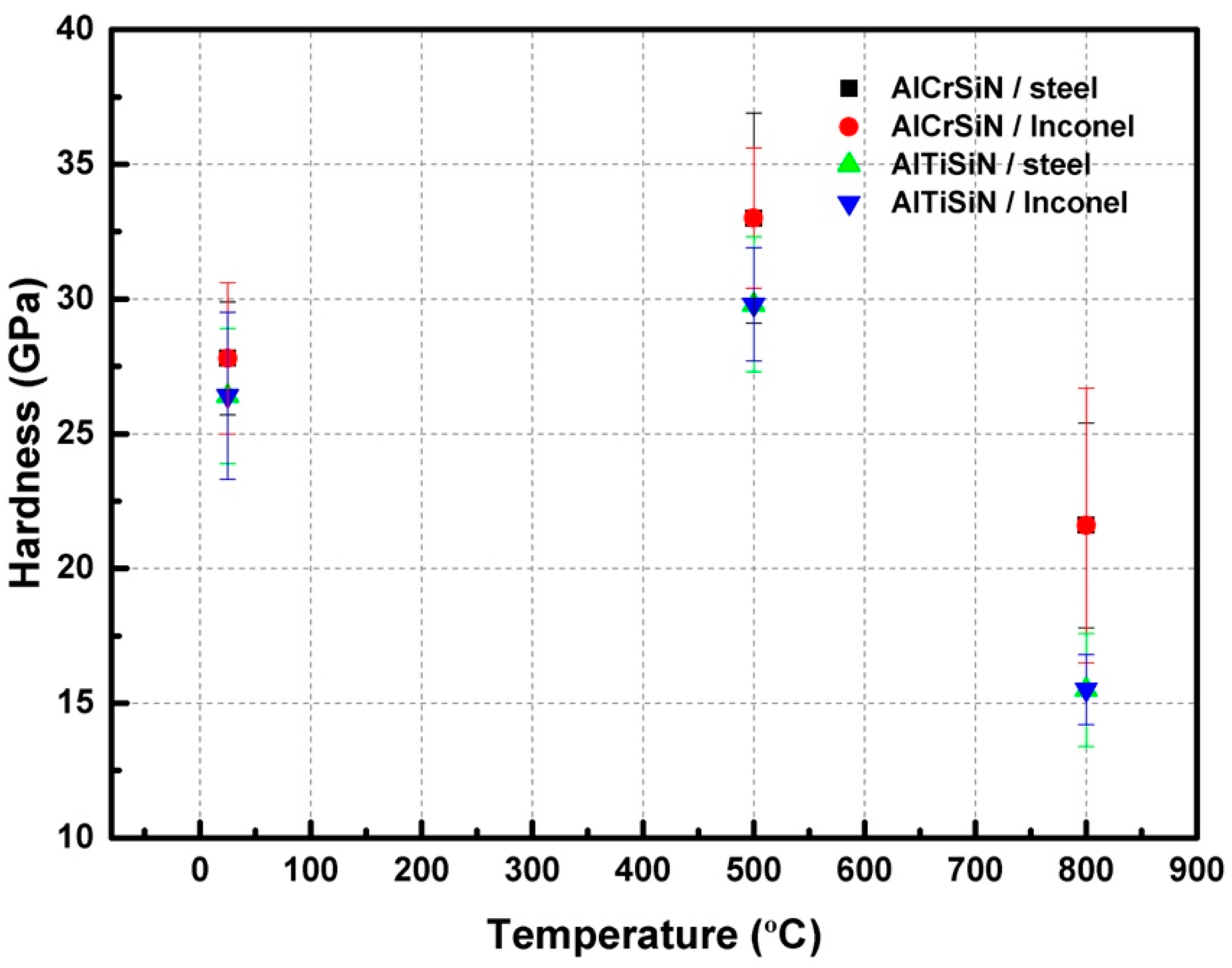
3.2. Mechanical Properties of the Coated Materials
Nanoindentation results are presented in
Table 5 and
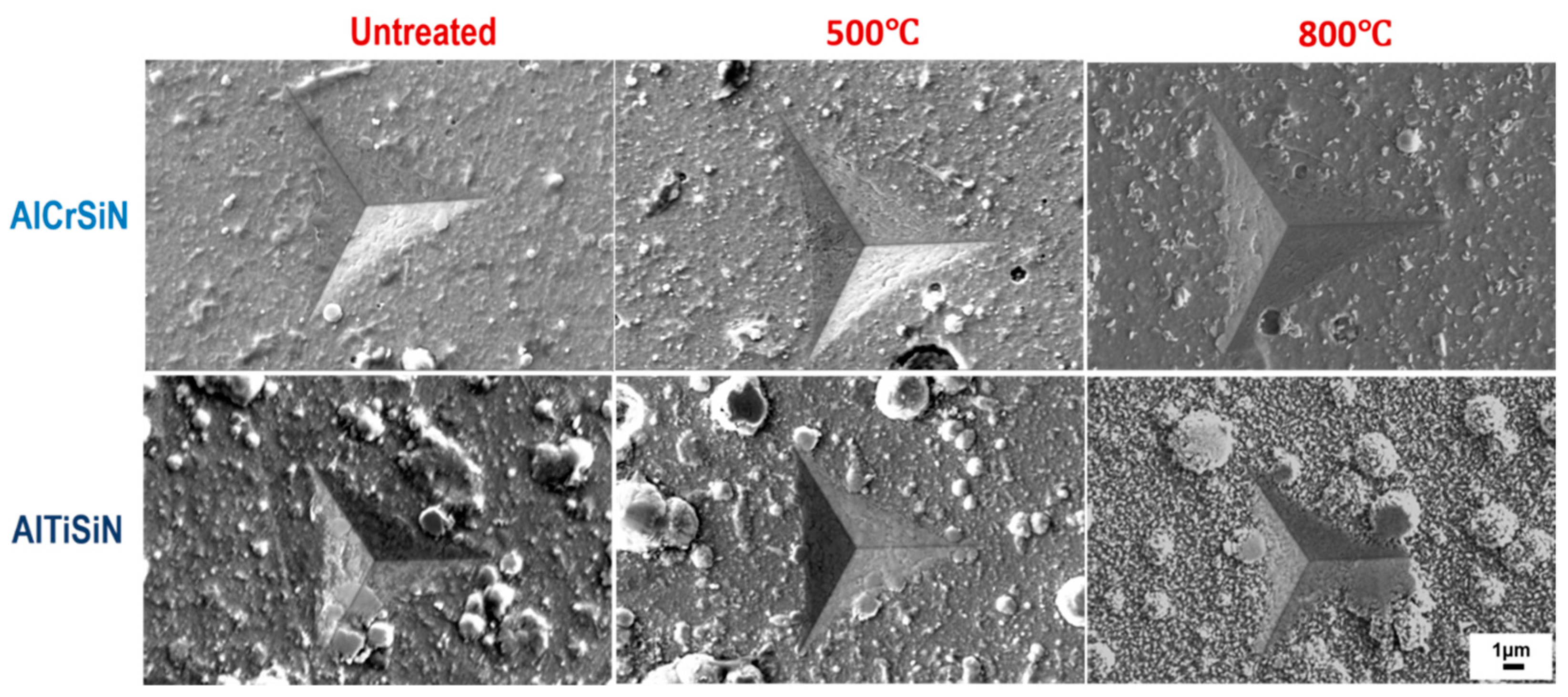
Figure 2. The images of the nanoindentation imprints are presented in
Figure 3. The hardness and elastic modulus ratio (H/E) was adopted to describe elastic deformation to failure and H
3/E
2 is the plasticity index to present the resistance to plastic deformation. Both are common parameters to characterize the mechanical performance and wear resistance of coatings [
43,
44]. Based on
Table 5, AlCrSiN coatings exhibited higher values of H
3/E
2 than AlTiSiN coatings when they all were deposited at the same substrate, indicating a better wear resistance response. It is elucidated that AlTiSiN coatings may present better wear resistance [
45]. However, it should be considered that the performance of the tool materials is a combination of both the substrate and coating. In this respect, Vickers test results of the substrate are presented in
Table 6.
It is seen how the samples that underwent a cycle of 500 °C presented an increase in the values of hardness, both for AlCrSiN and AlTiSiN coatings, regardless of the substrate. At 800 °C, hardness decreased. This may be attributed to the densification of the microstructure at moderate temperatures and the phase transformation at high temperatures where the cubic nitride phase transforms into a hexagonal nitrides phase [
21,
46].
Hardness of the substrates decreased in both cases, mainly after exposure at 800 °C. This is probably due to an increase in grain size and a modification of the precipitates [
35,
36].
Images of the indented coatings (
Figure 3) present droplets at the surface typical of the PVD process [
47]. The thermal treatment at 500 °C did not produce relevant changes in the surface. However, after the thermal treatment at 800 °C, there was a clear change in the surface, due to initial oxidation of the coatings. This oxidation is more evident in the case of the AlTiSiN coatings. This results in indentation imprints which deviates from the ideal shape, which gives rises to higher scattering in the mechanical values measured by this technique.
In
Figure 3, it is also shown how, for AlCrSiN coatings, some ring cracks appear around the indentation, which may indicate a lower fracture toughness compared with AlTiSiN coatings [
48].
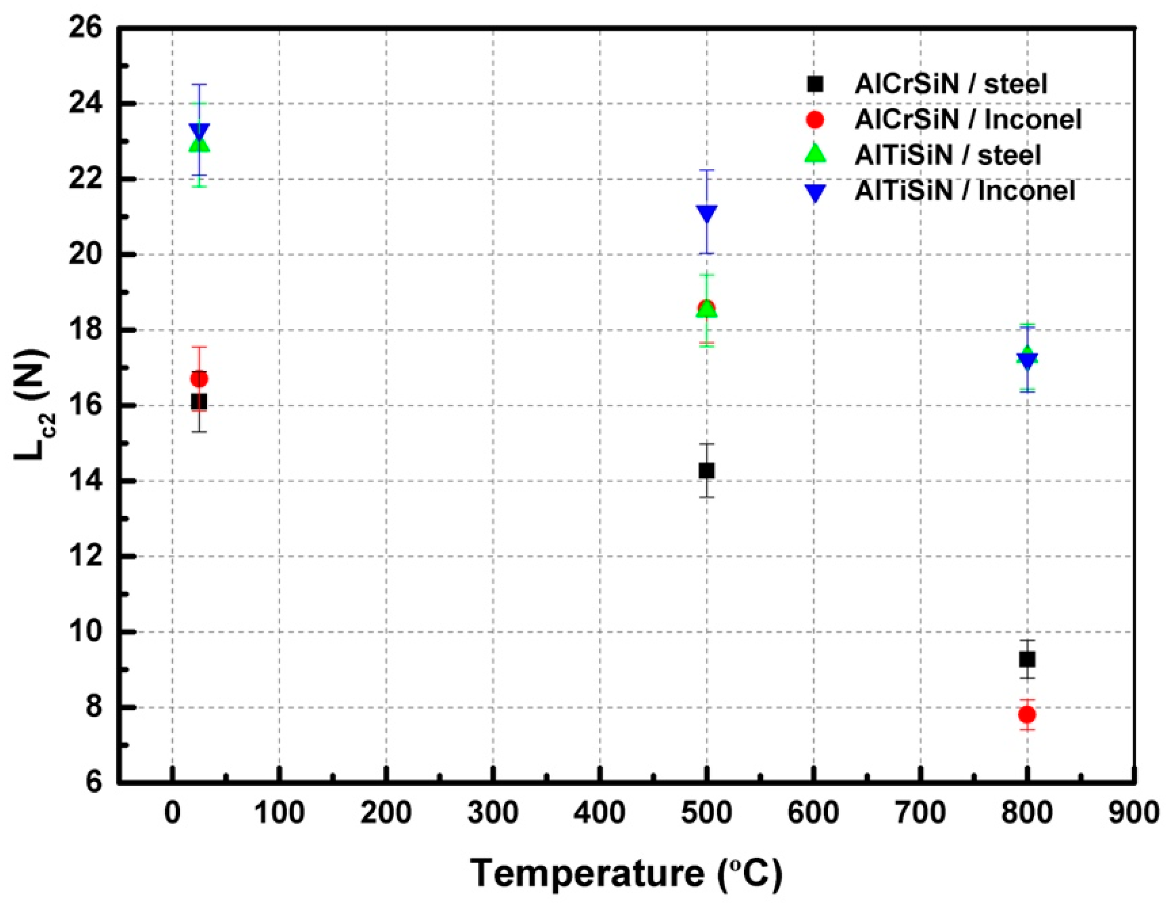
3.3. Adhesion Tests
Figure 4 presents the critical loads for delamination of all the materials.
Figure 4 shows how the appearance of decohesion of the coating for the AlTiSiN coating is higher than AlCrSiN, independent of the substrate. However, after thermal treatments at 500 °C, the coatings deposited on Inconel presented a better adhesion than those deposited on steel. Furthermore, the AlCrSiN on Inconel coating thermally treated at 500 °C exhibited an enhanced scratch resistance compared with the samples without thermal treatment. This enhancement may be due to the higher thermomechanical stability of Inconel as compared with steel. For thermal treatments at 800 °C, all coatings present lower adhesion, due to degradation of the coating as well as softening of the substrates.
Images obtained by optical microscopy; SEM of the scratch tracks are presented in
Figure 5,
Figure 6,
Figure 7 and
Figure 8 for AlCrSiN/steel, AlCrSiN/Inconel, AlTiSiN/steel, and AlTiSiN/Inconel, respectively. The coating thickness affects the scratch loads for adhesion and the direct comparison of performance by scratch with different coating/substrate system could not be taken in account. Therefore, both coatings have comparable thicknesses for every substrate. In
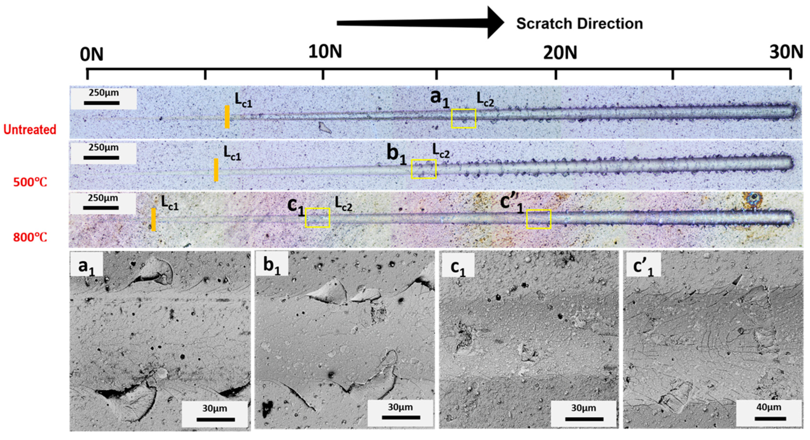
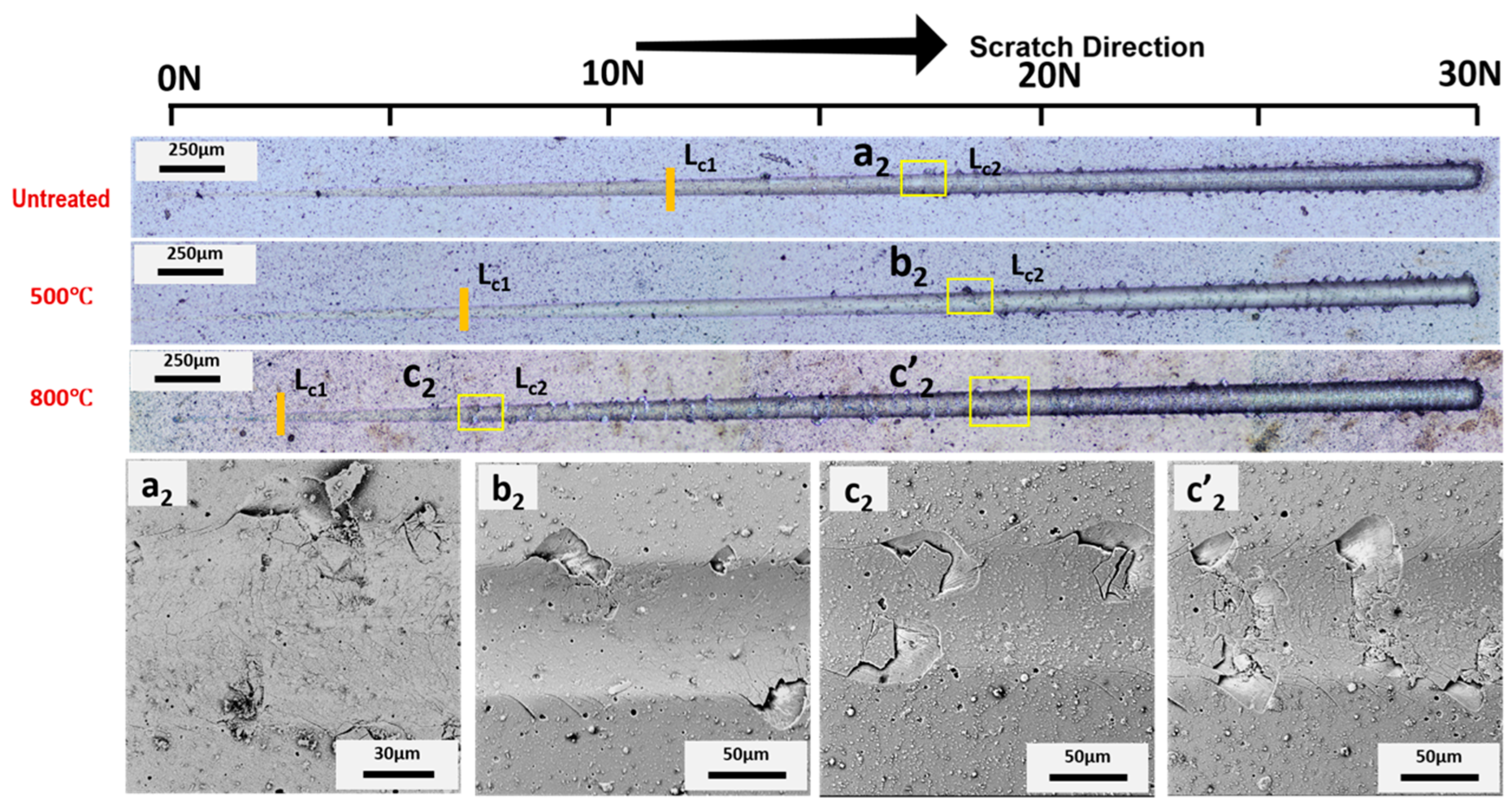
Figure 5 and
Figure 6, the scratch tracks of AlCrSiN on both substrates are presented. It is seen how plastic deformation, microcracking, and delamination are produced as load is increased. Stick–slip deformation induced by compressive stress appeared at the contour. External cracks in the scratch direction were formed as well. The load at which this failure appeared is labeled as critical load,
Lc1. As the load increased, transverse cracks appeared, induced by tensile stress, until the detachment of the coatings: this load is defined as
Lc2, which indicates failure of the interface of coated substrate.
After thermal treatment of the AlCrSiN coatings, critical loads were lower in the case of the steel substrate. In addition, the samples after thermal treatment at 800 °C presented a different type of damage, with more microcracking and less evident spalling. For the samples on the Inconel substrate, a slight improvement was appreciated for samples thermally treated at 500 °C, following the enhancement of mechanical properties observed previously. The mechanism for this enhancement may be the relaxation of the residual stress of AlCrSiN coating after 500 °C thermal treatment [
49], whereas the decrease in adhesion may due to a phase transformation forming the fcc-CrN phase into h-Cr
2N [
50].
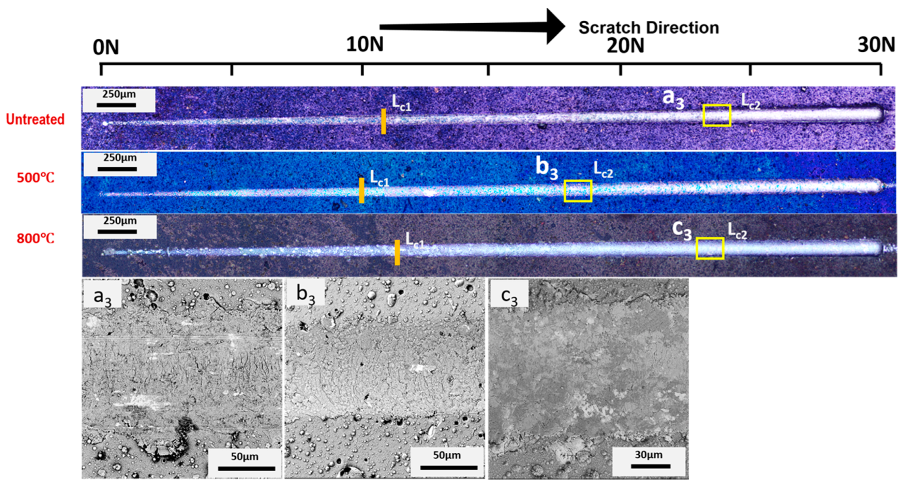
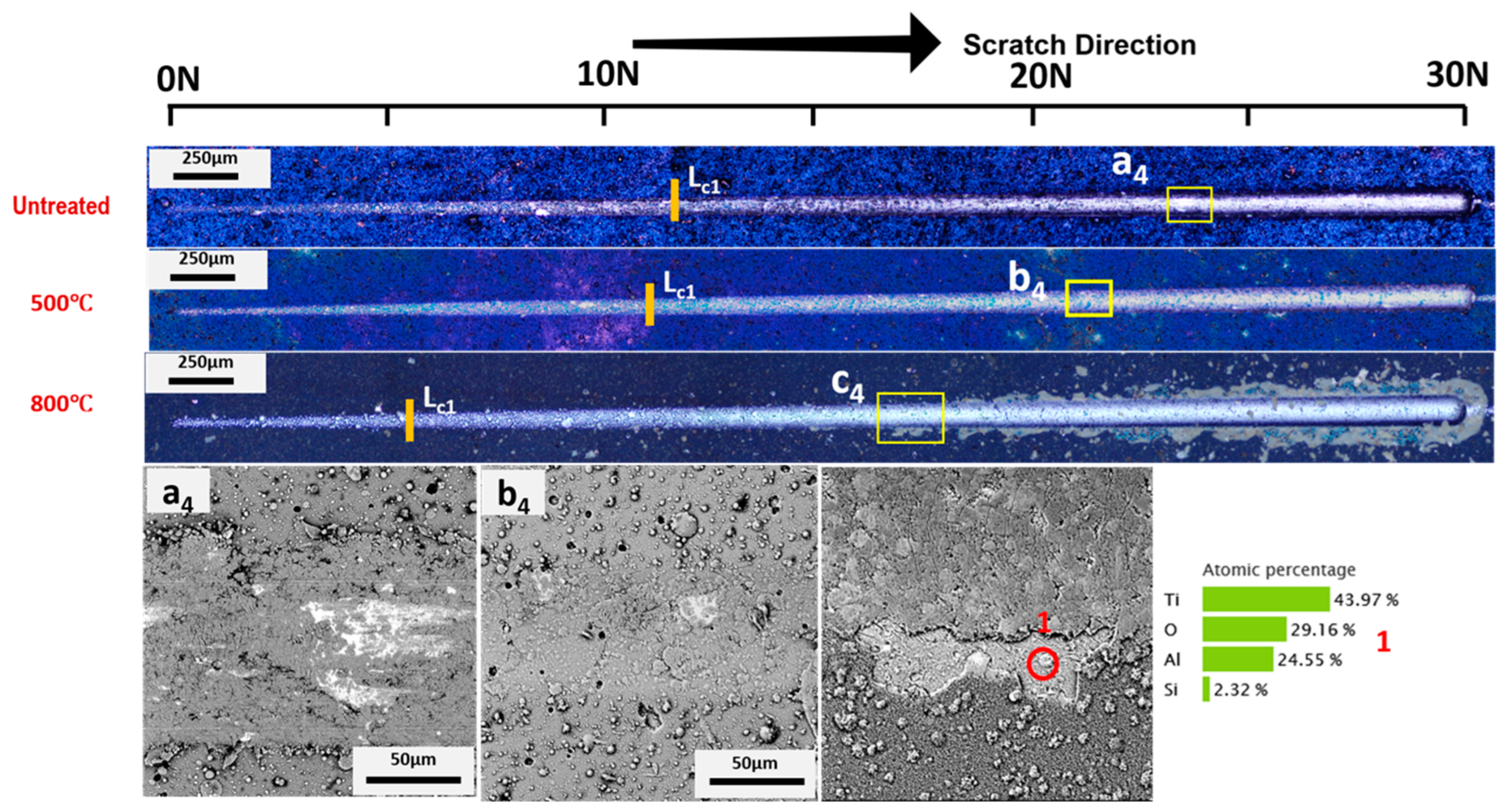
In the case of AlTiSiN coatings, as presented in
Figure 7 and
Figure 8, a small amount of deformation occurred at loads below 26 N [
3]. As the loading increased, adhesive failure occurred for AlTiSiN coatings. The coatings spalled from the middle of the trace of the scratch. After thermal treatment, the amount of delamination diminished for both temperatures. The difference for AlTiSiN coatings deposited on Inconel after thermal treatment, especially at 800 °C, compared with steel as the substrate, is that part of coating was delaminated. A substantial area of the coatings peeled off. EDX was conducted at the delaminated area, showing that the elements were similar with AlTiSiN coatings, and indicating that a thin layer of the coating remained on the surface. Therefore, the failure may be considered cohesive failure and not coating delamination. The reason for this may be the fragile layer formed in the thermal treatment process as well as the evident softening of the substrate. This phenomenon could be explained by the phase transformation of fcc-AlN into hcp-AlN after 800 °C thermal treatment [
51].
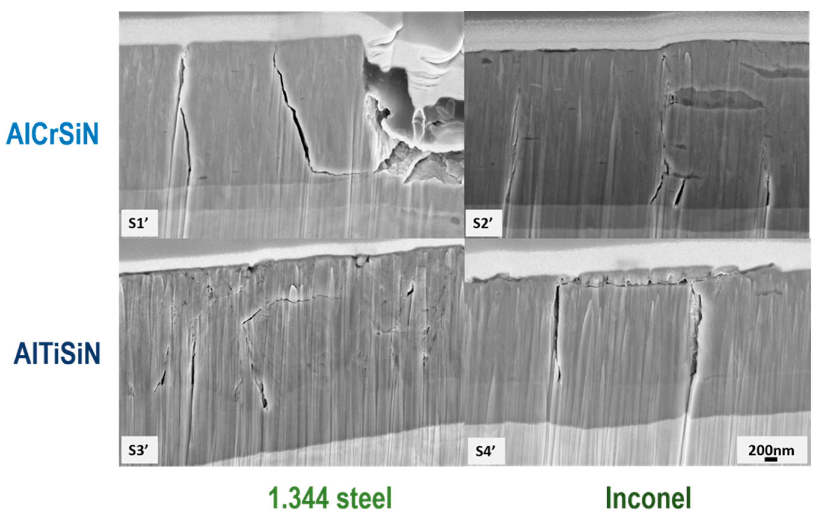
In
Figure 9, FIB cross-sections of all four coatings and microstructures are presented. The images were taken at the same load (16 N) in order to compare the behaviors between coatings.
Figure 9 shows how that all cracks were arrested by interface, indicating a good structural integrity of the substrate. Both coatings had a dense microstructure and a bonding layer, as shown previously [
26,
52].
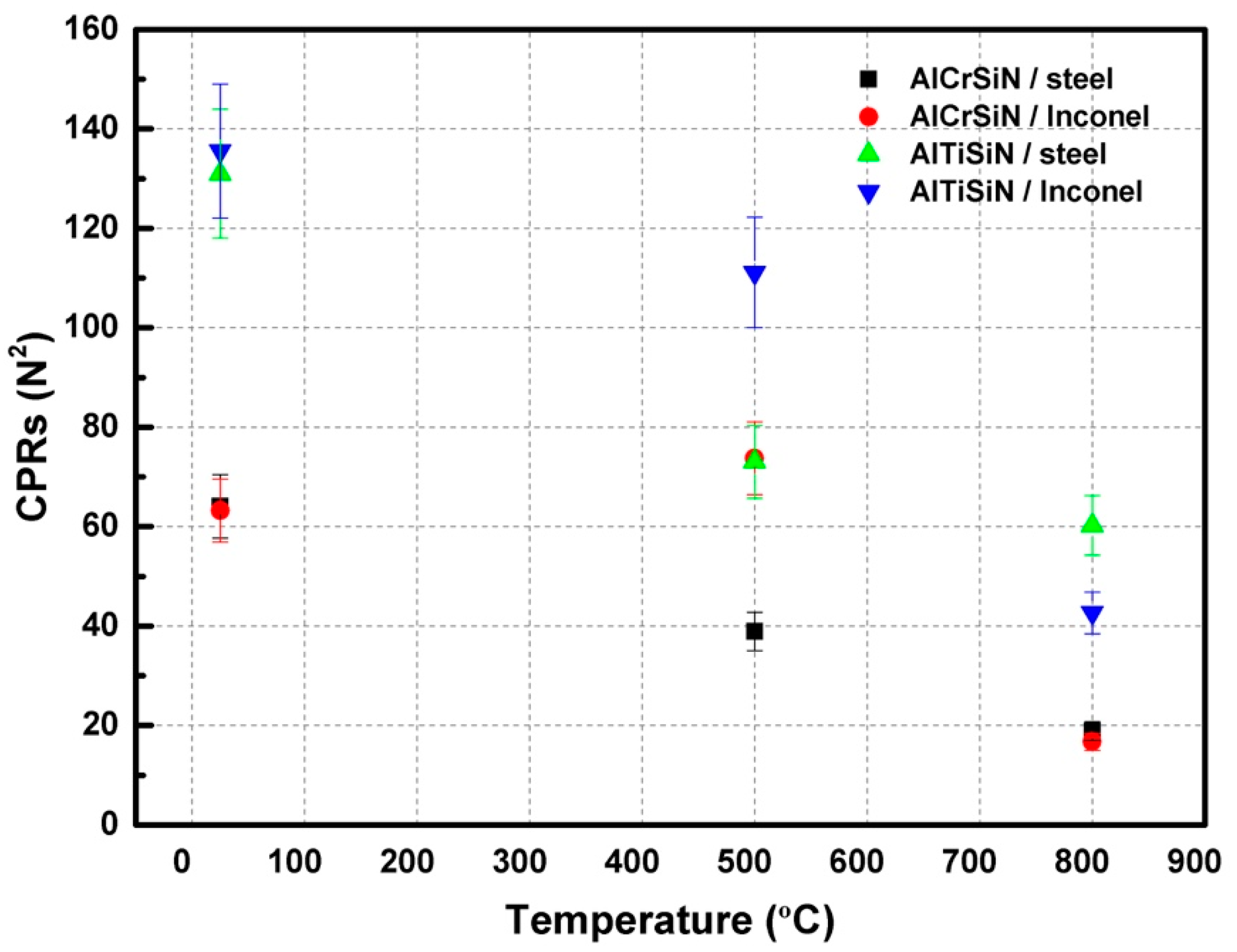
In order to rationalize the scratch resistance of the coatings, the scratch crack propagation resistance (
CPR) was calculated using Equation (2) [
53].
where
Lc1 is the critical load of start of lateral crack, and
Lc2 is the critical load of the start of delamination or spallation; the results are presented in
Figure 10.
The critical stress
σc is calculated by,
where
dc is the track width at
Lc2,
μ is the friction coefficient calculated by the friction force, and
νf is the Poisson rate of coatings. The surface energy of the known interfacial crack is defined by Equation (4) [
54,
55,
56]:
where
t and
Ef are the thickness and the elastic modulus of coatings, respectively. The values of
Ef were experimentally determined from
Table 5.
Crack propagation resistance (
CPR) is presented in
Figure 10, which shows how AlTiSiN coatings generally present higher
CPR than AlCrSiN coatings, independently of the substrate. After thermal treatments, the
CPR degraded in all cases, with the exception of AlCrSiN on Inconel, which presented a similar
CPR after thermal treatment at 500 °C.
The AlTiSiN/Inconel sample presented the highest value of
Gc = 321.5 J/m
2, as seen in
Table 7. The range of values was similar to those previously report by other researchers for similar hard coatings [
57,
58,
59]. Of all the studied systems, AlTiSiN/steel presented the higher adhesion energy. This coating also exhibited the highest
Gc after 800 °C thermal treatment. In comparison with AlTiSiN, AlCrSiN presented lower values for critical stress and adhesion energy, which was consistent with the analysis of the
CPR microstratch test.
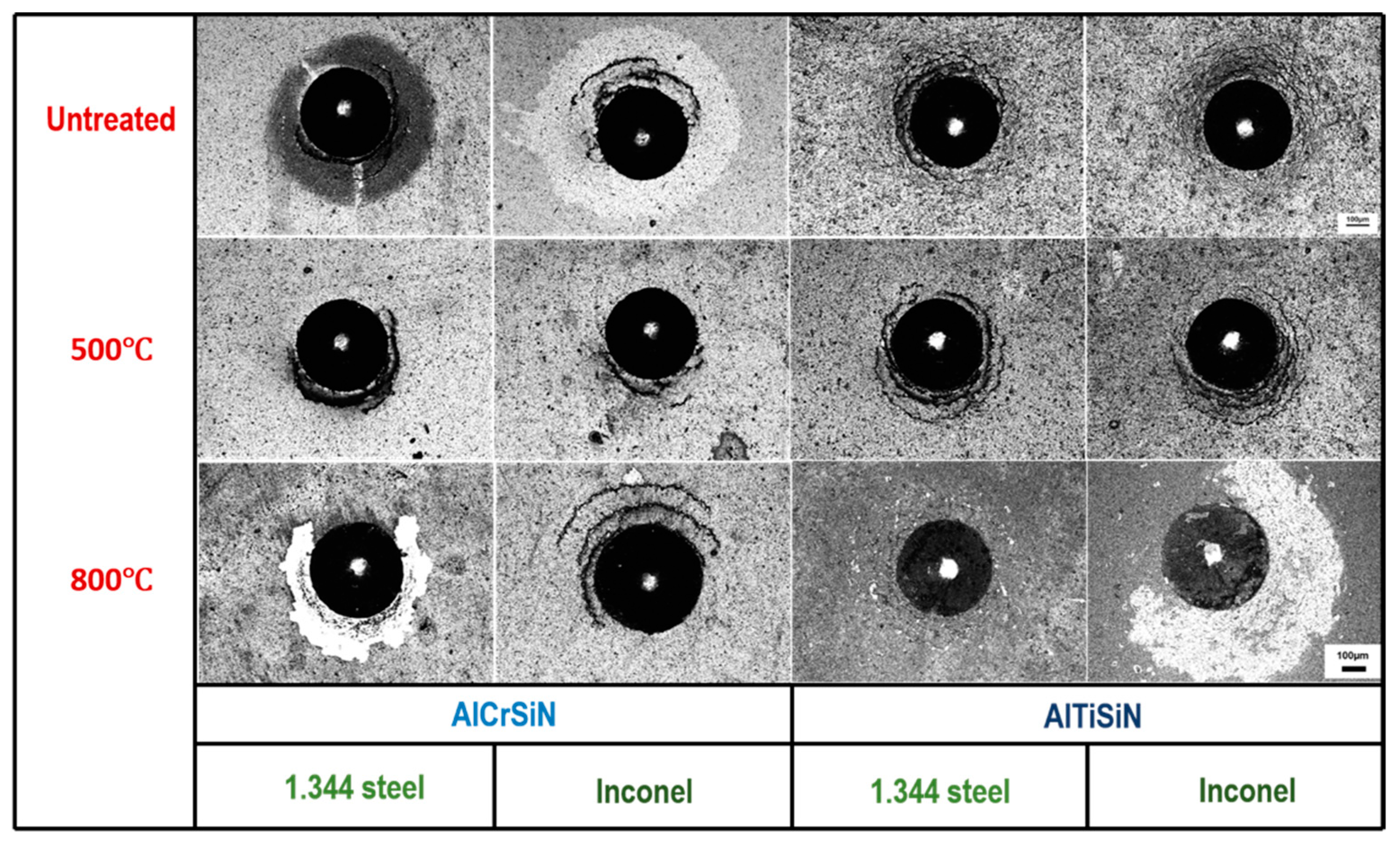
Figure 11 presents the results of the Mercedes Test at a normal load of 613 N. In all cases, radial cracks and partial ring cracks appeared. However, in the AlCrSiN/steel and AlTiSiN/Inconel systems after 800 °C thermal treatment, the vicinity of the indentation appeared with a high area of delamination. This high degree of delamination was also a consequence of the softening of the substrate, which resulted in higher deformation under contact loading and larger differential strains between the coating and substrate.
In the untreated AlCrSiN/Inconel sample, a similar phenomenon was noticed. In this case, delamination without spallation was observed, which indicated lower adhesion than after thermal treatment at 500 °C. This is coherent with the enhancement in CPR as observed in
Figure 10.
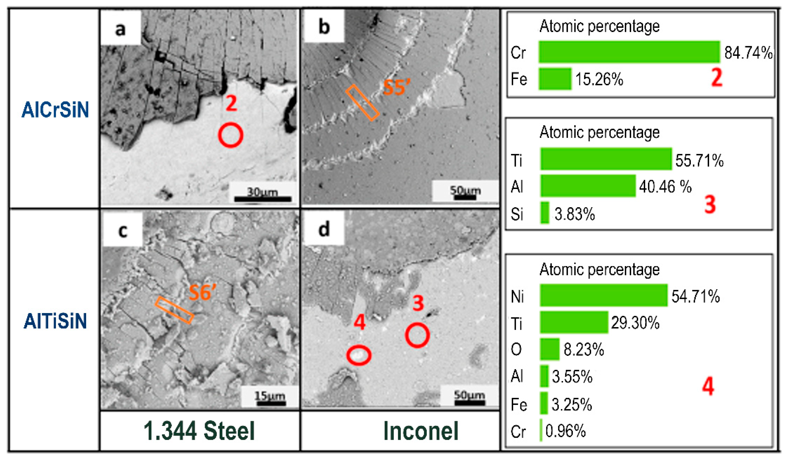
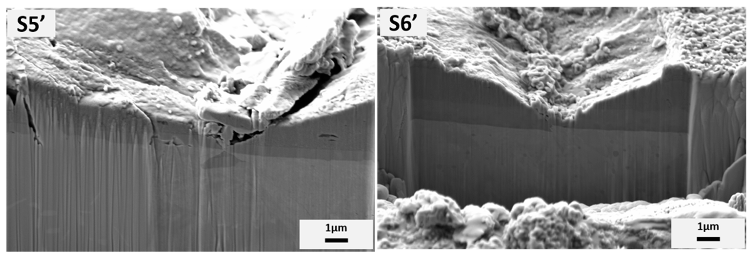
In order to further explore the damage at 613 N after 800 °C, the particular area of indentation after Mercedes test was magnified by SEM, as shown in
Figure 12, and EDX was performed to probe the elements of the delaminated area to ensure that the substrate was exposed. For AlCrSiN/steel, the exposed and light color area consisted of Cr and Fe. However, for AlTiSiN/Inconel, two contrasts appeared: shallow grey (circled as red 3) and white (circled as red 4). The SEM images demonstrate the delamination with large area of AlCrSiN/steel and AlTiSiN/Inconel at 613 N after 800 °C, but with traces of the coating still attached to the substrate. To further observe the internal deformation mechanisms, a cross-section at the areas was indicate as S5’and S6’, and is shown in
Figure 13. In all cases, it was seen how the cracks were contained at the coating, without propagating into the substrate.


 ,
, 


