
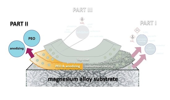
Chromate-Free Corrosion Protection Strategies for Magnesium Alloys—A Review: Part II—PEO and Anodizing

 ,
,  ,
,  , ,
, , 

 ,
, 
Abstract
1. Foreword
2. Evolution of Anodic Treatments for Mg Alloys
2.1. Fundamentals of Anodizing Below and Above the Breakdown Potential
2.2. Cr-Based Anodic Treatments
2.3. Cr-Free Anodic Treatments: State-of-the-Art Technologies and Patents

| Patent or Application No./Title | Observations | Ref. |
|---|---|---|
| WO/2017/064185 Corrosion inhibitor composition for magnesium or magnesium alloys | Method Salicylic acid derivatives encapsulated in micro-/nanoparticles as corrosion inhibiting molecules for Mg coatings. Outcome Corrosion protection and improved corrosion inhibiting efficiencies compared to 1,2,4-triazole and benzotriazole as known from US 6,569,264 B1. | [89] |
| Ru0002614917 Method for protective composite coatings production on magnesium alloy | Method Three steps treatment: PEO coating in silicate-based electrolyte followed by dipping in a tetrafluoroethylene telomer solution in acetone and then heat treatment. Outcome Increased service life and improved corrosion resistance, anti-friction, and hydrophobic properties of the coated material. | [90] |
| Ru0002543580 Method of obtaining protective coatings on magnesium alloys | Method Four steps treatment: PEO coating in silicate-based electrolyte, dipping in 8-oxyquinoline C9H7NO solution, followed by boiling in NaOH and posterior heat treatment. Outcome Reduction of corrosion rate, self-healing properties, increased service life in high humidity environment containing Cl. | [91] |
| US20140318974 Corrosion and erosion-resistant mixed oxide coatings for the protection of chemical and plasma process chamber components | Method Oxide layer formed by PEO with the presence of oxides of secondary elements (not present in the alloy) coming from different sources: (i) a soluble salt of the secondary element(s) in the electrolyte; (ii) an enrichment of the surface of the substrate metal with the secondary element(s) prior to PEO processing; (iii) a suspension of the secondary element(s) or oxide(s) of the secondary element(s) applied to the oxide of the metal after this has been formed by the PEO process. Outcome Corrosion and erosion-resistant mixed oxide coatings. | [92] |
| DE102011007424 A1 A process for producing a coating on the surface of a substrate based on light metals by plasma electrolytic oxidation | Method PEO in a clay-containing phosphate/silicate electrolyte. Outcome Fabrication of amorphous and glassy oxide surface layer. | [93] |
| EP1820882 Self-healing layer on nonferrous metals using polyoxometalates | Method Formation of an oxide or metallic layer comprising at least the POMs (e.g., Mo, V, W) and/or a crack-healing agent (e.g., CaO·Al2O3 or CaO·2Al2O3). These layers can be deposited/grown on the substrate via conventional anodizing, hard anodizing, PEO, and electroless deposition. Outcome Protective multifunctional layers with self-healing properties. | [94] |
| WO/2006/007972 Method for producing a hard coating with high corrosion resistance on articles made of anodizable metals or alloys | Method PEO & anodization process in a neutral/alkaline, phosphate-derivatives containing solution. Additional additives: Silicates, H2O2, alcohol, and either Zr, Ti, or Al-particles. Outcome High hardness and high corrosion resistance coatings. | [95] |
| US20040238368 Magnesium anodization methods | Method Anodization process in a phosphate alkaline electrolyte containing a sequestering agent to suppress plasma during anodization and a tertiary amine. Outcome -Controlled coating thickness and porosity by choosing various combinations of both current density and time (e.g., high current density for a short time produce a less porous layer). -The addition of a small amount of a phosphonate such as “Dequest” 2066 or 2041 to the anodizing bath allows the anodizing process to proceed with both pulsed waveforms and also DC. | [96] |
| WO/2003/083181 Process and device for forming ceramic coatings on metals and alloys, and coatings produced by this process | Method PEO (at high frequency pulses) supported by sonic acoustic vibrations for the use of stable hydrosols as electrolytes (for the introduction of fine-disperse particles). Outcome -Controlled micro-discharges during PEO process. -Improved energy efficiency. -Low-porous, 150 µm thick, hard microcrystalline ceramic coatings. | [97] |
| WO/2003/016596 Magnesium anodization system and methods | Method Anodization process in a phosphate alkaline electrolyte containing a sequestering agent and a tertiary amine. Outcome Process to create oxide layers with sequestering agents in the form of ethylene diamine tetramethylene phosphonic acid and DEQUEST. | [98] |
| CN106119846 a Method for preparing corrosion resistant and abrasion-resistant coating on surface of magnesium alloy | Method Two-step treatment process: micro-arc oxidation treatment followed by microwave plasma vapor deposition. Outcome Improved corrosion and wear properties. | [99] |
| WO/2016/010541 Electroceramic coating for magnesium alloys | Method Two steps process: Plasma oxidative deposition in a fluoride-containing solution followed by different organic/inorganic surface finishing. Outcome Improved corrosion resistance. | [100] |
| WO/2015/008064 High thermal conductivity insulated metal substrates produced by plasma electrolytic oxidation | Method PEO in alkaline solution, specified voltage/current parameters, and pulses. Outcome Improved corrosion protection along with high thermal conductivity achieved on surfaces with high dielectric strength. | [101] |
| US20090223829 Micro-arc assisted electroless plating methods | Method PEO followed by electroless Ni plating (EN). Outcome Duplex coatings revealed superior corrosion resistance to salt spray testing as compared to the traditional EN coatings. | [102] |
| US20080248214 Method of forming an oxide coating with dimples on its surface | Method AC, DC, or DC pulse treatments in an alkaline electrolyte. Outcome Wear and corrosion prevention. | [103] |
| US20070270235 Golf club head and method for making the same | Method Sample degreased by weak alkaline, cleaned, and dried followed by PEO in silicate-phosphate electrolyte at 10–45 °C. Outcome PEO layers developed on golf components. | [104] |
| EP 1793019 A2 Multivalent electrolytic process for the surface treatment of nonferrous metallic material | Method Anodization process in an alkaline electrolyte (pH 7–10) based on phosphate/ammonia, NaOH/KOH/LiOH. Followed by the coloring stage (dye). Outcome Colored oxide layers. | [105] |
| Il152307 Oxidising electrolytic method for obtaining a ceramic coating at the surface of a metal | Method Standard PEO process in an alkaline solution (alkali hydroxide + oxyacid salt of an alkali metal). Outcome Specimens with semiconductive properties. | [106] |
| 131996 Method of anodizing magnesium metal and magnesium alloys | Method Anodization of Mg using alkaline electrolytes containing ammonia or an amine and phosphoric acid or a water-soluble phosphate salt. Outcome Details of different processes methodology. | [107] |
| WO/2003/002776 Method of anodizing of magnesium and magnesium alloys and producing conductive layers on an anodized surface | Method Anodization electrolyte: hydroxylamine, phosphate, nonionic surfactant, alkali hydroxide. Process followed by rendering anodized Mg with an electrolyte containing Ni, pyrophosphate, hypophosphite, and thiocyanate/lead nitrate. Outcome Conductive layers on anodized Mg surface. | [108] |
| WO/2002/031230 Method for anodizing magnesium and magnesium alloy components or elements | Method and outcome Anodization process using alkaline electrolytes containing phosphates/aluminates. | [109] |
| WO/1998/042892 Anodizing magnesium and magnesium alloys | Method and outcome Anodization of magnesium or magnesium alloys using an electrolytic solution (preferably derived from phosphoric acid) containing ammonia, amines, or both. | [110] |
| US5385662 A Method of producing oxide ceramic layers on barrier layer forming metals and articles produced by method | Method and outcome Plasma chemical oxidation of Mg and other metals. Electrolyte: Phosphate, borate, fluoride, stabilizer urea, hexamethylendi(or tetra)amine, glycol/glycerin. | [111] |
| DE4104847 A1 Production of uniform ceramic layers on metals surfaces by spark discharge- used for metal parts of aluminium, titanium, tantalum, niobium, zirconium, magnesium, and their alloys with large surface areas | Method and outcome Metal parts are immersed in an electrolytic bath (without cathode) and connected to a controllable power source supplying time-dependent, multiphase, periodic current. | [112] |
| US4976830 A Method of preparing the surfaces of magnesium and magnesium alloys | Method and outcome Mg anodization in electrolyte containing alkali hydroxide, borate/sulfonate, phosphate/fluoride. | [113] |
| US 3956080 Coated valve metal article formed by spark anodizing | Method and outcome PEO conducted in alkaline electrolyte based on silicates and containing oxyacid of Te or Se. | [114] |
3. Corrosion of Anodized Mg Alloys
4. Effect of Energy Input and Electrolyte Composition on Coating Protection Properties
4.1. Energy Input
4.2. Electrolyte Composition
4.2.1. Organic and Inorganic Soluble Additives
4.2.2. Particle Addition
4.2.3. Organic Electrolytes
5. Post-Treatment
| Post-Treatment/Introduced Species | Alloy Electrolyte PEO Treatment Conditions | Post-Treatment | Thickness/ Phases | Corrosion Data | Ref. |
|---|---|---|---|---|---|
| Ce(NO3)3 (CeO2, Ce2O3) | AM50 Na2SiO3, KOH AC square waveform 420/−60 V, 500 Hz, 10 min, 10 °C | Immersion Ce(NO3)3 3 g/L, 20 min, 10 g/L, 20 min 10 g/L, 3 h H2O2, H3BO3, 30 °C | PEO 30–40 μm Post-treatment dissolution ~10–15 µm Mg2SiO4, MgO CeO2, Ce2O3 | ↑ Ce(NO3)3, ↑ tsealing→↑ Rcorr (EIS) | [280] |
| La(NO3)3 (La(OH)3) | AZ91 Na2SiO3,NaOH, Na5P3O10 DC 0.5 A/cm2, 2 min | Immersion 12 g/L La(NO3)3 30, 40, or 50 °C 10 or 30 min | PEO 30 µm MgO, Mg3(PO4)2, Mg2SiO4, La(OH)3 | PDP in 0.1 M Na2SO4, 0.05 M NaCl (Ecorr; icorr) Untreated: −1.88 V; 2 × 10⁻⁵ A/cm2 PEO: −1.87 V; 1.5 × 10⁻⁶ La 30 °C 10 min: −1.73 V; 8 × 10⁻⁷ A/cm2 La 30 °C 30 min: −1.83 V; 4 × 10⁻⁷ A/cm2 La 40 °C 10 min: −1.82 V; 5 × 10⁻⁷ A/cm2 La 40 °C 30 min: −1.69 V; 2.8 × 10⁻⁷ A/cm2 La 50 °C 10 min: −1.73 V; 9 × 10⁻⁷ A/cm2 La 50 °C 30 min: −1.65 V; 2.8 × 10⁻⁷ A/cm2 | [278] |
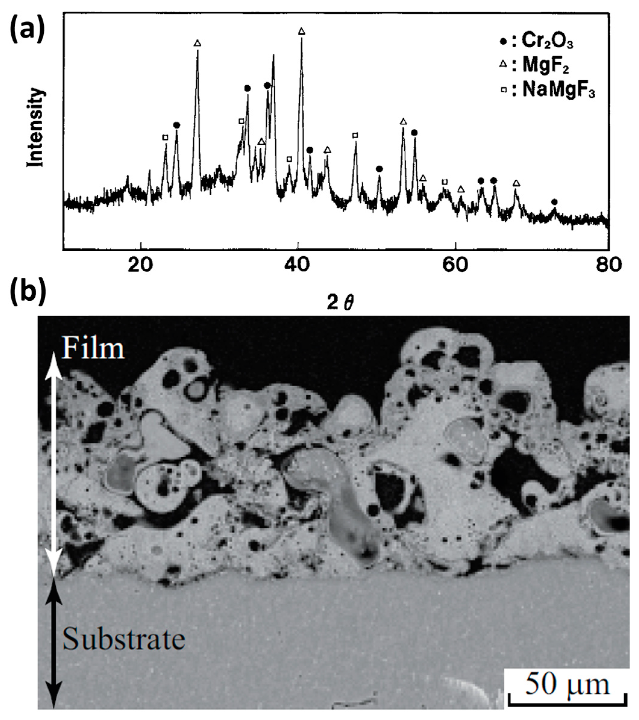
| Na2MoO4 (MoO3) | Mg-Li NaSiO3, NaOH, triethanolamine DCpulsed5 A/dm2, 2000 Hz; 15% duty cycle,10 min | Immersion 20 g/L Na2MoO4, 4 g/L NaF, 30 wt.% H2O2, 50 °C, 2 h | PEO and PEO-Mo 25 μm NaMgF3, Mg2SiO4, MgO, MoO3 | PDP5min in 3.5 wt.% NaCl (Ecorr; icorr) Untreated: −1.685 V; 7.045 × 10⁻⁴ A/cm2 PEO: −1.446 V; 6.4 × 10⁻⁷ A/cm2 PEO-Mo: −1.354 V; 2.5 × 10⁻⁷ A/cm2 | [284] |
| Ce(NO3)3, Na2SnO3, Octadecylphosphonic acid (ODP) | AZ91D Na2SiO3, KOH, NaF AC 420 V/60 V, 500 Hz 200 mA cm−2, 200 s | Immersion Ce(NO3)3, 180 min 30 °C; Na2SnO3 30 min 80 °C; 0.1672 g L−1 ODP in ethanol 24 h 23 °C | 13 µm | Surface damage area after 7 days NSST (ASTM B117) PEO: 9.2 ± 2.4% PEO-Ce: 1.9 ± 1.3% PEO-Sn: 5.2 ± 0.5% PEO-ODP: 1.1 ± 0.1% EIS in 0.5 wt.% NaCl (|Z|10mHz) 3 h/7 days: PEO-Ce: 106/2 × 105 Ωcm2 PEO-ODP: 7 × 10⁶/3 × 104 Ωcm2 | [263] |
| Self-healing 8-hydroxyquinoline (8 HQ) | MA8 Na2SiO3, NaF bipolar pulses, anodic voltage 30 to 300 V, rate 0.45 V/s; cathodic pulse potentiostatic 30 V, 50% duty cycle, 300 Hz, 10 min, 25 °C | Immersion 3 g/L 8HQ (8-hydroxyquinoline C9H7NO) 120 min dried 140 °C, 20 min | 16 µm | PDP15 min in 3 wt.% NaCl (Ecorr; icorr) Untreated: − 1.59 V; 5.3 × 10⁻⁵ A/cm2 PEO: −1.51 V; 8.1 × 10⁻⁷ A/cm2 PEO-8HQ: − 1.44 V; 8.6 × 10⁻⁸ A/cm2 H2 evolution in 3 wt.% NaCl-40 days (Pcorr) Untreated: 1.133 mm/year PEO-coating: 0.154 mm/year PEO-8HQ: 0.128 mm/year | [322] |
| Self-healing NH4NO3 (LDH) | AZ31 Na2SiO3, KOH, KF DCpulsed0.3 A/cm2, 800 Hz, 10% duty cycle, Vend360 V. | Immersion 0.02 M NH4NO3 (pH 12.8) 120 °C for 12 h | PEO 6.5 μm PEO-LDH 7 μm MgO, Mg(OH)2, LDH (Mg-Al LDH) | PDP400 s in phosphate buffer saline-PBS 37 °C (Ecorr; icorr) Untreated: −1.45 V; 1.66 × 10⁻⁵ A/cm2 LDH: −1.12 V; 3.34 × 10⁻⁵ A/cm2 PEO: −1.22 V; 9.45 × 10⁻⁶ A/cm2 PEO-LDH: −1.2 V; 3.92 × 10⁻⁶ A/cm2 | [288] |
| Inhibitors Ce(NO3)3 Ce3+ ions or 8- hydroxyquinoline (8HQ) Sol-gel TiO2 + (GPTMS). silane-based alkosol | ZK30 NaOH, Al(OH)3, Na3PO4, KF DC 125 mA/cm2,70 V, 10 min | Immersion 0.005 M Ce(NO3)3 or 0.005 M (8-hydroxyquinoline C9H7NO) 8HQ, 30 min Sol-gel dip-coating TiO2,(3-glycidoxypropyl)-trimethoxysilane (GPTMS) 1:2 vol., 100 s. cured 120 °C, 80 min | anodized film 0.7–3.0 µm sol-gel 3–4 µm | Rcorr: ZK_Anod_Ce3+_SG > ZK_Anod_SG > ZK_8HQ_SG > ZK_Anod anodized alloy = ZK_Anod sol-gel sealed = SG immersed in Ce3+ or 8HQ = Ce3+ or 8HQ | [323] |
| Inhibitor 1,2,4-triazole, Sol-gel TiO2 + silane-based sols (GPTMS)+ (PTMS) | ZE41 Na2SiO3, KF, NaOH poly(ethylene oxide), DC3 mA/cm2, 12 min, 20 ± 2 °C | Immersion 0.01 M 1,2,4-triazole, 15 s Sol-gel dip-coating TiO2, (3-glycidoxypropyl)-trimethoxysilane (GPTMS), phenyltrimethoxisilane (PTMS), 40 s suspended at room temperature, relative humidity 60% in open air, 1 h cured 120 °C,1.5 h | anodized film 1.8 ± 0.1µm sol-gel 6.3 ± 0.2 µm | Rcorr: ZE_Anod_Tr_SG > ZE_Anod_SG > ZE_SG substrate = ZE sol-gel sealed = SG anodizing = Anod immersed in 1,2,4-triazole = Tr | [324] |
| KH2PO4 (P) Na2SiO3 (Si) sol-gel SiO2 | AM50B AM60B KOH, NaAlO2, K3PO4 DC 20–30 A/dm2 7 or 14 min | Immersion 12% KH2PO4 (P) 60 °C, 5 min Immersion 5% Na2SiO3 (Si) 95 °C, 15 min Sol-gel sealing 14 mL tetra-ethylortho-silicate (TEOS), 2 wt.% Methyl-triethoxysilane (MTES), 1.2 mL ethanol, 2.5 mL H2O, 0.35 mL HCl, 1 min, annealing 160 °C, 3 h, ×3 repeated | 10 or 25 µm MgO, MgAl2O4 | PDP in 3.5 wt.% NaCl (Ecorr; icorr) AM50B Untreated: −1.55 V; 1.2 × 10⁻⁵ A/cm2 10 µm PEO: −1.52 V; 1.45 × 10⁻⁷ A/cm2 25 µm PEO: −1.47 V; 1.65 × 10⁻⁷ A/cm2 PEO-P: −1.62 V; 2.6 × 10⁻⁸ A/cm2 PEO-Si: −1.45 V; 2.4 × 10⁻⁸ A/cm2 PEO- SiO2: −1.39 V; 6.57 × 10⁻⁹ A/cm2 AM60B Untreated: −1.55 V; 8.2 × 10⁻⁶ A/cm2 10 µm PEO: −1. 54 V; 1.04 × 10⁻⁷ A/cm2 25 µm PEO: −1.56 V; 1.51 × 10⁻⁷ A/cm2 PEO-P: −1.67 V; 3.2 × 10⁻⁸ A/cm2 PEO-Si: −1.49 V; 2.2 × 10⁻⁸ A/cm2 PEO-SiO2: −1.44 V; 1.2 × 10⁻⁸ A/cm2 | [86] |
| sol-gel TiO2 | AZ91D NaAlO2, KOH DC 25 mA/cm2 25 min, 25–30 °C | Sol-gel sealing tetra-n-butyl orthotitanate (TBT), ethanol, ethyl acetoacetate, 1 min, ×3 repeated heated 150 and 350 °C,1 h | PEO 4µm PEO-TiO2 6µm MgO, MgAl2O4, MgTi2O5 | PDP in 3.5 wt.% NaCl (Ecorr; icorr) Untreated: −1.509 V; 2.352 × 10⁻⁶ A/cm2 PEO: −1.479 V; 1.607 × 10⁻⁶ A/cm2 PEO-TiO2-(150 °C): −1.316 V; 7.96 × 10⁻⁸ A/cm2 PEO-TiO2-(350 °C): −1.261 V; 4.838 × 10⁻⁷ A/cm2 | [285] |
| sol-gel SiO2-ZrO2 | AZ91D NaAlO2, NaOH, small quantity of Montmorillonite and acacia gum pulsed voltage, increased to 180–200 V, then 0.5 h | Sol-gel sealing stoichiometric amounts of ethyl silicate, zirconyl chloride octahydrate ethanol, 1 min drying 150 °C, 1 h | Sol-gel layer 5 µm | PDP10min in 3.5 wt.% NaCl (Ecorr; icorr) Untreated: −1.428 V; 3.395 × 10⁻⁵ A/cm2 PEO: −1.326 V; 3.921 × 10⁻⁷ A/cm2 PEO- SiO2-ZrO2: −0.406 V; 1.577 × 10⁻⁹ A/cm2 | [286] |
| Inhibitor loaded and sol-gel sealed | AZ91 Na3PO4, KOH DC pulsed: ton:toff = 1:9, 250 Hz, 40 mA cm−2, 60 s | Inhibitors: Na glycolate (Gly), Na 4-aminosalicylate (4AmSal), Na 2,6-pyridinedicarboxylate (PDC). Sol-gel: (3-glycidoxypropyl)-trimethoxysilane (GPTMS) and Ti (IV) propoxide (TPOT) | 2.5 µm PEO + 2.5 µm sol-gel | EIS in 0.5 wt.% NaCl (|Z|10mHz), 2 h/336 h PEO-SG: 108 Ωcm2/104 Ωcm2 PEO-Gly-SG: 107 Ωcm2/107 Ωcm2 PEO-4AmSal-SG: 108 Ωcm2/2 × 107 Ωcm2 PEO-PDC-SG: 108 Ωcm2/3 × 106 Ωcm2 | [325] |
| Inhibitor loaded halloysite nanotubes (HNT) | AZ31 Na2SiO3, KOH, NaF Pulsed DC: 5000 Hz, 10% duty cycles, 40 mA cm−2, 10 min | Immersion: 10 min in an aqueous solution 20 g L–1 of inhibitor loaded HNTs, 22 °C. Inhibitors: 8-hydroxyquinoline (8HQ), ammonium molybdate (Mo), ammonium metavanadate (V) | 30 µm PEO MgO, MgSiO4 | LEIS in 0.05 M NaCl up to 34.1 h over 300 × 2000 μm and 250 × 500 μm artificial defects All PEO-HNT-inhibitor coatings provided self-healing of small defects; only PEO-HNT-V partially restored large defect. | [252] |
| Self-healing PEO-Ce-LDH-P | AZ31 NaAlO2, NaOH, AC: 100 Hz, +250 V/−50 V, 26% duty cycle, 600 s | Ce-conversion coating: 50 °C, 2 h; LDH: NaNO3 125 °C, 12 h; Phytic acid immersion: pH11, 80 °C, 1 h | PEO-Ce 1.2 µm PEO-Ce-LDH 2.7 µm PEO-Ce-LDH-P 2.8 µm | EIS in 3.5 wt.% NaCl (|Z|10mHz) PEO-Ce-LDH-P 30 min: 105 Ωcm2 7 days: 2 × 10⁵ Ωcm2 21 days: 106 Ωcm2 | [292] |
| Superhydrophobic PEO-HDT-FTDS-oil impregnation | AZ31B NaSiO3, KOH, KF DC: 100 mA cm−2 10 min | HDT: 100 °C H2O 50 min + Hydrophobization with FDTS and oil impregnation by solvent exchange with Krytox GPL 103 | ~20 µm Wettability PEO-HDT-FTDS: 173° PEO-HDT-FTDS-oil: 123° | EIS in 3.5 wt.% NaCl (|Z|10mHz), 0/15 days PEO-HDT-FTDS: 5 × 10⁶ Ωcm2/2 × 106 Ωcm2 PEO-HDT-FTDS-oil: const. ~108 Ωcm2 | [304] |
| Superhydrophobic PEO-LDH-SLIPS | AZ91D NaSiO3, NaOH Pulsed DC 30 mA cm−2, 100 Hz, duty cycle 10%, 300 s. | +Mo-intercalated Mg-Al-LDH, 120 °C, 8–48 h + PFDS + PFPE | ~9 µm 121° wettability | EIS in 3.5 wt.% NaCl (|Z|10mHz) 0 days: 2 × 10⁸ Ωcm2 18 days: 2 × 10⁶ Ωcm2 Water repellance, active protection by Cl- and MoO42- exchange, regeneration of barrier layer | [305] |
| Silane coupling agent (SCA) | 99.9% Mg silicate electrolyte 300 V, 500 Hz, 2.5% duty cycle, 10 min, ultrasonic frequency 60 kHz | Immersion NaOH (1, 2, 3 mol/L), 60 °C, 1 h Immersion silane coupling agent (SCA) KH550 C2H5OH, H2O, 1:9:1 vol. heated | - | PDP in 0.9 wt.% NaCl (Ecorr; icorr) PEO: −1.517 V; 2.135 × 10⁻² A/cm2 PEO-NaOH(1M)-SCA: −1.488 V; 2.73 × 10⁻³ A/cm2 PEO-NaOH(2M)-SCA: −1.464 V; 8.927 × 10⁻⁴ A/cm2 PEO-NaOH(3M)-SCA: −1.442 V; 2.383 × 10⁻⁴ A/cm2 | [315] |
| E-coating electroless | ZE41 Tagnite treatment up to ~20 μm thick film | E-coating bath solution (water 71–82 wt.%, epoxy resin 16–26 wt.%, TiO2 1.3 wt.%), 10 s, baked 171 °C, 25 min | PEO 20 μm | PDP in 5 wt.% NaCl (Ecorr; icorr) PEO: 10−2 –10−3 mA/cm2 Sealed:10−6 –10−6.5 mA/cm2 ↑Ecorr | [317] |
| Titanium organic polymer (TOP) | AZ91D Na2SiO4, KOH DCpulsed, 360–400 V, 1–2 h | Immersion titanium organic polymer (TOP), solvent 1:20, applied vacuum, 1 min, cured 50 °C, 30 min ×2, 3 repeated | PEO 20 µm sealing layer 3–5 µm | PDP in 3.5 wt.% NaCl (Ecorr; icorr) Untreated: −1.574 V; 3.176 × 10⁻⁵ A/cm2 PEO: −1.555 V; 2.962 × 10⁻⁷ A/cm2 PEO-TOP: −1.119 V; 4.107 × 10⁻¹⁰ A/cm2 | [318] |
| Epoxy-silane (ES) | ZE41 NaOH, Na2SiO3, KF 7.5 g/L poly(ethylene oxide) DC 3 mA/cm2, 9 min, 20 °C | Immersion silane (0.14 M), epoxy (0.98 M), DETA amine (0.37 M), ethanol, and acetone 5 s ×4 repeated cured 150 °C, 1.5 h | PEO 1.8 µm PEO-ES 10 µm | PDP10 min in 0.5 M NaCl (Ecorr; icorr) Untreated vs. PEO: ↓icorr by 2–4 orders of magnitude Immersion in 0.6 M NaCl for 31 days Untreated: filiform corrosion, multiple pits, most commonly located at the edge. PEO-ES: no signs of corrosion onset nor any indication of coating delamination | [319] |
| Polymer (MALPB) | AZ31B KOH, Na3PO4, KF, Al(NO3)3 DC 5 mA/cm2 up to 80 V 30 min, 30 °C | Immersion Maleic anhydride-g-poly(1,2-butadiene) polymer (MALPB) Mn = 1020 1 min cured 30 to 180 °C (10 °C/min) 15 min | PEO 3.5 µm, MALPB 10 µm | PDP30 min in 3.5 wt.% NaCl (Ecorr; icorr) MALPB: −1.35 V PEO: −1.48 V PEO-MALPB: −1.19 V NSST-scratch test 50 g/L NaCl, 1–2 mL/h, 200, 400 h corrosion PEO-MALPB < MALPB PEO-MALPB almost unchanged after 200 h, smaller spoiled dots after 400 h | [320] |
| Epoxy resin Ni-P | AZ31 Na2SiO4, KOH 600 V, 600 Hz, 10% duty cycle, 20 °C, 10 min | Immersion commercial epoxy resin (24 h drying) Pretreatment: -NaOH, 75 °C,40 min -silane solution, 20 °C, 3 min, -cured 100 °C, 30 min. -PdCl2, HCl, 20 °C, 1 min -NaH2PO2, 20 °C, 10 min Electroless Ni–P plating (25 g/L NiSO4 × 6H2O, 23 g/L NaH2PO2·H2O, 20 g/L, Na3C6H5O7·2H2O, 24 g/L NH4F, 3 mg/L CS(NH2)2, 75 °C 20 min | Ni-P 5 μm polymer 130 μm PEO 8 μm | PDPin 3.5 wt.% NaCl (Ecorr; icorr) PEO: −1.444 V; 8.826 × 10⁻⁸ A/cm2 PEO-epoxy: −1.357 8.594 × 10⁻⁹ A/cm2 PEO-epoxy-Ni-P: −0.416 V; 5.979 × 10⁻⁶ A/cm2 EIS immersion time, pitting onset: PEO-epoxy 408 h PEO-epoxy-Ni-P 624 h | [321] |
6. Perspectives
Author Contributions
Funding
Institutional Review Board Statement
Informed Consent Statement
Data Availability Statement
Acknowledgments
Conflicts of Interest
References
- Esmaily, M.; Svensson, J.E.; Fajardo, S.; Birbilis, N.; Frankel, G.S.; Virtanen, S.; Arrabal, R.; Thomas, S.; Johansson, L.G. Fundamentals and advances in magnesium alloy corrosion. Prog. Mater. Sci. 2017, 89, 92–193. [Google Scholar] [CrossRef]
- Atrens, A.; Johnston, S.; Shi, Z.; Dargusch, M.S. Viewpoint—Understanding Mg corrosion in the body for biodegradable medical implants. Scr. Mater. 2018, 154, 92–100. [Google Scholar] [CrossRef]
- Vaghefinazari, B.; Wierzbicka, E.; Visser, P.; Posner, R.; Jordens, G.; Arrabal, R.; Matykina, E.; Mohedano, M.; Blawert, C.; Zheludkevich, M.L.; et al. Chromate-Free Corrosion Protection Strategies for Magnesium Alloys—A Review: Part III—Inhibitors. Materials 2022, 15, 8489. [Google Scholar] [CrossRef]
- Vaghefinazari, B.; Wierzbicka, E.; Visser, P.; Posner, R.; Jordens, G.; Arrabal, R.; Matykina, E.; Mohedano, M.; Blawert, C.; Zheludkevich, M.L.; et al. Chromate-Free Corrosion Protection Strategies for Magnesium Alloys—A Review: Part I—Pre-Treatment and Conversion Coatings. Materials 2022, in press. [Google Scholar]
- Arrabal, R.; Mohedano, M.; Matykina, E. Electrochemical Surface Treatments for Mg Alloys. In Encyclopedia of Materials: Metals and Allloys; Caballero, F.G., Ed.; Elsevier: Oxford, UK, 2022; pp. 87–112. [Google Scholar]
- Narayanan, T.S.N.S.; Park, I.S.; Lee, M.H. Strategies to improve the corrosion resistance of microarc oxidation (MAO) coated magnesium alloys for degradable implants: Prospects and challenges. Prog. Mater. Sci. 2014, 60, 1–71. [Google Scholar] [CrossRef]
- Sampatirao, H.; Radhakrishnapillai, S.; Dondapati, S.; Parfenov, E.; Nagumothu, R. Developments in plasma electrolytic oxidation (PEO) coatings for biodegradable magnesium alloys. Mater. Today Proc. 2021, 46, 1407–1415. [Google Scholar] [CrossRef]
- Darband, G.B.; Aliofkhazraei, M.; Hamghalam, P.; Valizade, N. Plasma electrolytic oxidation of magnesium and its alloys: Mechanism, properties and applications. J. Magnes. Alloy. 2017, 5, 74–132. [Google Scholar] [CrossRef]
- Santos-Coquillat, A.; Martínez-Campos, E.; Sánchez, H.M.; Moreno, L.; Arrabal, R.; Mohedano, M.; Gallardo, A.; Rodríguez-Hernández, J.; Matykina, E. Hybrid functionalized coatings on Metallic Biomaterials for Tissue Engineering. Surf. Coat. Technol. 2021, 422, 127508. [Google Scholar] [CrossRef]
- Yerokhin, A.L.; Nie, X.; Leyland, A.; Matthews, A.; Dowey, S.J. Plasma electrolysis for surface engineering. Surf. Coat. Technol. 1999, 122, 73–93. [Google Scholar] [CrossRef]
- Chen, D.; Wang, R.; Huang, Z.; Wu, Y.; Zhang, Y.; Wu, G.; Li, D.; Guo, C.; Jiang, G.; Yu, S.; et al. Evolution processes of the corrosion behavior and structural characteristics of plasma electrolytic oxidation coatings on AZ31 magnesium alloy. Appl. Surf. Sci. 2018, 434, 326–335. [Google Scholar] [CrossRef]
- Bonilla, F.A.; Berkani, A.; Liu, Y.; Skeldon, P.; Thompson, G.E.; Habazaki, H.; Shimizu, K.; John, C.; Stevens, K. Formation of anodic films on magnesium alloys in an alkaline phosphate electrolyte. J. Electrochem. Soc. 2002, 149, B4–B13. [Google Scholar] [CrossRef]
- Ono, S.; Asami, K.; Osaka, T.; Masuko, N. Structure of anodic films formed on magnesium. J. Electrochem. Soc. 1996, 143, L62–L63. [Google Scholar] [CrossRef]
- Guo, K.W. A Review of Magnesium/Magnesium Alloys Corrosion and its Protection. Recent Pat. Corros. Sci. 2010, 2, 13–21. [Google Scholar] [CrossRef]
- Otto, K. Method of Coating Articles of Magnesium and an Electrolytic Bath Therefor. U.S. Patent 4,620,904, 11 April 1986. [Google Scholar]
- Lewis, J. Keeler. Protective Coating for Magnesium. U.S. Patent 1,574,290, 23 February 1926. [Google Scholar]
- Gmelins Handbuch der Anorganischen Chemie, Magnesium Teil A, System-Nummer 27, 8. Auflage; Verlag Chemie, GmbH: Weinheim/Bergstrasse, Germany, 1952; p. 760.
- Brown, S.D.; Kuna, K.J.; Van, T.B. Anodic Spark Deposition from Aqueous Solutions of NaAlO2 and Na2SiO3. J. Am. Ceram. Soc. 1971, 54, 384–390. [Google Scholar] [CrossRef]
- Markov, G.A.; Markova, G.V. Method of fabrication of anodes for electrolytic capacitors. USSR Inventor’s Certificate no. 526961. Bull. Invent. 1976, 32. (In Russian) [Google Scholar]
- Fyedorov, V.A.; Belozerov, V.V.; Velikosel’skaya, N.D.; Bulychev, S.I. Composition and structure of the hardened aluminum alloys surface layer obtained by microarc oxidation. Fiz. Khim. Obrab. Mater. 1988, 4, 92. (In Russian) [Google Scholar]
- Kurze, P.; Banerjee, D.; Kletke, H.J. Method of Producing Oxide Ceramic Layers on Barrier Layer-Forming Metals and Articles Produced by the Method; Electro Chemical Engineering GmbH: Zug, Switzerland, 1998. [Google Scholar]
- Kurze, P.; Schreckenbach, J.; Schwarz, T.; Krysmann, W. Coating by Anodic Oxidation with Spark Discharge. Metalloberflaeche 1986, 40, 539–540. [Google Scholar]
- Snezhko, L.A.B.; Yu, M.; Chernenko, V.I.; Nevkrytyi, V.I. Pulsed conditions for production of silicate coatings in a spark discharge (English translation of Zaschita Metallov). Prot. Met. 1980, 16, 287–289. [Google Scholar]
- Snezhko, L.A.B.; Chernenko, V.I. Energy Parameters of the Process of Formation of Silicate Coatings on Aluminum under Spark Discharge Conditions. Elektron. Obrab. Mater. 1983, 2, 25–28. [Google Scholar]
- Gordienko, P.S.; Gnedenkov, S.V.; Sinebryukov, S.L.; Zavidnaja, A.G. Mechanism of the Growth of Microarc Oxidizing Coatings on Titanium. Electronnaya Obrab. Mater. 1991, 2, 42–46. [Google Scholar]
- Gordienko, P.S.; Vasilevskij, V.A.; Zheleznov, V.V. Investigation of Introduction of Phosphorus to Oxide Coating of Titanium in Electrochemical Oxidation. Electronnaya Obrab. Mater. 1991, 4, 21–24. [Google Scholar]
- Bartak, D.E.; Lemieux, B.E.; Woolsey, E.R. Hard Anodic Coating for Magnesium Alloys. U.S. Patent 5470664A, 28 November 1995. [Google Scholar]
- Schmeling, E.L.; Roschenbleck, B.; Weidemann, M.H. Method of Producing Protective Coatings that are Resistant to Corrosion and Wear on Magnesium and Magnesium Alloys. U.S. Patent 4978432A, 18 December 1990. [Google Scholar]
- Curran, J.; Hutchins, S.; Shrestha, S. Process for the Enhanced Corrosion Protection of Valve Metals. U.S. Patent WO2010112914A1, 7 October 2010. [Google Scholar]
- Fatkullin, A.R.; Parfenov, E.V.; Yerokhin, A.; Lazarev, D.M.; Matthews, A. Effect of positive and negative pulse voltages on surface properties and equivalent circuit of the plasma electrolytic oxidation process. Surf. Coat. Technol. 2015, 284, 427–437. [Google Scholar] [CrossRef]
- Nominé, A.; Martin, J.; Henrion, G.; Belmonte, T. Effect of cathodic micro-discharges on oxide growth during plasma electrolytic oxidation (PEO). Surf. Coat. Technol. 2015, 269, 131–137. [Google Scholar] [CrossRef]
- Nominé, A.; Martin, J.; Noël, C.; Henrion, G.; Belmonte, T.; Bardin, I.V.; Kovalev, V.L.; Rakoch, A.G. The evidence of cathodic micro-discharges during plasma electrolytic oxidation process. Appl. Phys. Lett. 2014, 104, 081603. [Google Scholar] [CrossRef]
- Matykina, E.; Berkani, A.; Skeldon, P.; Thompson, G.E. Real-time imaging of coating growth during plasma electrolytic oxidation of titanium. Electrochim. Acta. 2007, 53, 1987–1994. [Google Scholar] [CrossRef]
- Parfenov, E.V.; Nevianzeva, R.R.; Gorbatkov, M.V.; Yerokhin, A.L. Plasma Electrolytic Surface Treatment: Modelling, Diagnostics, Control; Mashiostroenie: Moscow, Russian, 2014; Volume 380, p. 52. (In Russian) [Google Scholar]
- Parfenov, E.V.; Yerokhin, A.; Nevyantseva, R.R.; Gorbatkov, M.V.; Liang, C.J.; Matthews, A. Towards smart electrolytic plasma technologies: An overview of methodological approaches to process modelling. Surf. Coat. Technol. 2015, 269, 2–22. [Google Scholar] [CrossRef]
- Suminov, I.; Belkin, P.; Epelfeld, A.; Ludin, V.; Krit, B.; Borisov, A.M. Plasma Electrolytic Surface Modification of Metals and Alloys; Technosfera: Moscow, Russian, 2011; Volume 2, 512p. (In Russian) [Google Scholar]
- Gnedenkov, S.V.; Sinebryukhov, S.L.; Mashtalyar, D.V.; Nadaraya, K.V. Anticorrosion and Wear-Resistant Composite Coatings at the Surface of Magnesium Alloys. In Proceedings of the European Corrosion Congress, EUROCORR 2015, Graz, Austria, 6–10 September 2015; pp. 55–61. [Google Scholar]
- Gnedenkov, S.V.; Sinebryukhov, S.L.; Minaev, A.N.; Mashtalyar, D.V.; Egorkin, V.S.; Gnedenkov, A.S.; Nadaraia, K.V. Multifunctional Composite Coatings on Metals and Alloys for Marine Applications. In Proceedings of the International Offshore and Polar Engineering Conference, Rhodes, Greece, 26 June –2 July 2016; pp. 291–297. [Google Scholar]
- Gnedenkov, S.V.; Sinebryukhov, S.L.; Sergienko, V.I. Composite Multifunctional Coatings Formed on the Metals and Alloys by Plasma Electrolytic Oxidation; Dal’nauka: Vladivostok, Russian, 2013. (In Russian) [Google Scholar]
- Mohedano, M.; Luthringer, B.J.C.; Mingo, B.; Feyerabend, F.; Arrabal, R.; Sanchez-Egido, P.J.; Blawert, C.; Willumeit-Römer, R.; Zheludkevich, M.L.; Matykina, E. Bioactive plasma electrolytic oxidation coatings on Mg-Ca alloy to control degradation behaviour. Surf. Coat. Technol. 2017, 315, 454–467. [Google Scholar] [CrossRef]
- Blawert, C.; Sah, S.P.; Scharnagl, N.; Kannan, M.B. Plasma Electrolytic Oxidation/Micro-Arc Oxidation of Magnesium and its Alloys. In Surface Modification of Magnesium and Its Alloys for Biomedical Applications; Woodhead Publishing: Sawston, UK, 2015; pp. 193–234. [Google Scholar]
- Matykina, E.; Arrabal, R.; Mohedano, M.; Mingo, B.; Gonzalez, J.; Pardo, A.; Merino, M.C. Recent advances in energy efficient PEO processing of aluminium alloys. Trans. Nonferrous Met. Soc. China 2017, 27, 1439–1454. [Google Scholar] [CrossRef]
- Mohedano, M.; Matykina, E.; Arrabal, R.; Mingo, B.; Zheludkevich, M.L. PEO of rheocast A356 Al alloy: Energy efficiency and corrosion properties. Surf. Interface Anal. 2016, 48, 953–959. [Google Scholar] [CrossRef]
- Hickling, A.; Ingram, M.D. Contact glow-discharge electrolysis. Trans. Faraday Soc. 1964, 60, 783–793. [Google Scholar] [CrossRef]
- Krysmann, W.; Kurze, P.; Dittrich, K.H.; Schneider, H.G. Process characteristics and parameters of anodic oxidation by spark discharge (ANOF). Cryst. Res. Technol. 1984, 19, 973–979. [Google Scholar] [CrossRef]
- Monfort, F.; Matykina, E.; Berkani, A.; Skeldon, P.; Thompson, G.E.; Habazaki, H.; Shimizu, K. Species separation during coating growth on aluminium by spark anodizing. Surf. Coat. Technol. 2007, 201, 8671–8676. [Google Scholar] [CrossRef]
- Nominé, A.; Troughton, S.C.; Nominé, A.V.; Henrion, G.; Clyne, T.W. High speed video evidence for localised discharge cascades during plasma electrolytic oxidation. Surf. Coat. Technol. 2015, 269, 125–130. [Google Scholar] [CrossRef]
- Khaselev, O.; Weiss, D.; Yahalom, J. Structure and composition of anodic films formed on binary Mg–Al alloys in KOH–aluminate solutions under continuous sparking. Corros. Sci. 2001, 43, 1295–1307. [Google Scholar] [CrossRef]
- Arrabal, R.; Matykina, E.; Viejo, F.; Skeldon, P.; Thompson, G.E. Corrosion resistance of WE43 and AZ91D magnesium alloys with phosphate PEO coatings. Corros. Sci. 2008, 50, 1744–1752. [Google Scholar] [CrossRef]
- Dunleavy, C.S.; Curran, J.A.; Clyne, T.W. Time dependent statistics of plasma discharge parameters during bulk AC plasma electrolytic oxidation of aluminium. Appl. Surf. Sci. 2013, 268, 397–409. [Google Scholar] [CrossRef]
- Martin, J.; Nominé, A.; Brochard, F.; Briançon, J.L.; Noël, C.; Belmonte, T.; Czerwiec, T.; Henrion, G. Delay in micro-discharges appearance during PEO of Al: Evidence of a mechanism of charge accumulation at the electrolyte/oxide interface. Appl. Surf. Sci. 2017, 410, 29–41. [Google Scholar] [CrossRef]
- Clyne, T.W.; Troughton, S.C. A review of recent work on discharge characteristics during plasma electrolytic oxidation of various metals. Int. Mater. Rev. 2018, 64, 127–162. [Google Scholar] [CrossRef]
- Mohedano, M.; Arrabal, R.; Mingo, B.; Pardo, A.; Matykina, E. Role of particle type and concentration on characteristics of PEO coatings on AM50 magnesium alloy. Surf. Coat. Technol. 2018, 334, 328–335. [Google Scholar] [CrossRef]
- Shi, Z.; Song, G.; Atrens, A. The corrosion performance of anodised magnesium alloys. Corros. Sci. 2006, 48, 3531–3546. [Google Scholar] [CrossRef]
- Song, G.-L.; Shi, Z. Corrosion mechanism and evaluation of anodized magnesium alloys. Corros. Sci. 2014, 85, 126–140. [Google Scholar] [CrossRef]
- Arrabal, R.; Matykina, E.; Skeldon, P.; Thompson, G.E.; Pardo, A. Transport of species during plasma electrolytic oxidation of WE43-T6 magnesium alloy. J. Electrochem. Soc. 2008, 155, C101. [Google Scholar] [CrossRef]
- Chen, J.; Wang, J.; Han, E.; Dong, J.; Ke, W. AC impedance spectroscopy study of the corrosion behavior of an AZ91 magnesium alloy in 0.1M sodium sulfate solution. Electrochim. Acta 2007, 52, 3299–3309. [Google Scholar] [CrossRef]
- Liang, J.; Guo, B.; Tian, J.; Liu, H.; Zhou, J.; Liu, W.; Xu, T. Effects of NaAlO2 on structure and corrosion resistance of microarc oxidation coatings formed on AM60B magnesium alloy in phosphate-KOH electrolyte. Surf. Coat. Technol. 2005, 199, 121–126. [Google Scholar] [CrossRef]
- Kim, K. Formation of endogenous MgO and MgAl2O4 particles and their possibility of acting as substrate for heterogeneous nucleation of aluminum grains. Surf. Interface Anal. 2015, 47, 429–438. [Google Scholar] [CrossRef]
- Blawert, C.; Dietzel, W.; Ghali, E.; Song, G. Anodizing Treatments for Magnesium Alloys and Their Effect on Corrosion Resistance in Various Environments. Adv. Eng. Mater. 2006, 8, 511–533. [Google Scholar] [CrossRef]
- Kaseem, M.; Fatimah, S.; Nashrah, N.; Ko, Y.G. Recent progress in surface modification of metals coated by plasma electrolytic oxidation: Principle, structure, and performance. Prog. Mater. Sci. 2021, 117, 100735. [Google Scholar] [CrossRef]
- Alabbasi, A.; Kannan, M.B.; Walter, R.; Stormer, M.; Blawert, C. Performance of pulsed constant current silicate-based PEO coating on pure magnesium in simulated body fluid. Mater. Lett. 2013, 106, 18–21. [Google Scholar] [CrossRef]
- Arrabal, R.; Mota, J.M.; Criado, A.; Pardo, A.; Mohedano, M.; Matykina, E. Assessment of duplex coating combining plasma electrolytic oxidation and polymer layer on AZ31 magnesium alloy. Surf. Coat. Technol. 2012, 206, 4692–4703. [Google Scholar] [CrossRef]
- Cai, Q.; Wang, L.; Wei, B.; Liu, Q. Electrochemical performance of microarc oxidation films formed on AZ91D magnesium alloy in silicate and phosphate electrolytes. Surf. Coat. Technol. 2006, 200, 3727–3733. [Google Scholar] [CrossRef]
- Curran, J.A.; Clyne, T.W. The thermal conductivity of plasma electrolytic oxide coatings on aluminium and magnesium. Surf. Coat. Technol. 2005, 199, 177–183. [Google Scholar] [CrossRef]
- Guo, H.; An, M. Effect of surfactants on surface morphology of ceramic coatings fabricated on magnesium alloys by micro-arc oxidation. Thin Solid Film. 2006, 500, 186–189. [Google Scholar] [CrossRef]
- Vladimirov, B.V.; Krit, B.L.; Lyudin, V.B.; Morozova, N.V.; Rossiiskaya, A.D.; Suminov, I.V.; Epelfeld, A.V. Microarc oxidation of magnesium alloys: A review. Surf. Eng. Appl. Electrochem. 2014, 50, 195–232. [Google Scholar] [CrossRef]
- Buzzard, R.W.; Wilson, J.H. Anodic Coating of Magnesium Alloys. In Part of Journal of Research of the National Bureau of Standards; Research Paper RP964; U.S. Department of Commerce: Washington, DC, USA, 1937. [Google Scholar]
- Adamson, K.G.; King, J.F.; Unsworth, W. Evaluation of the DOW 17 Treatment for Magnesium Alloys. In National Tecbnical Information Service; Defence, M.O., Ed.; U.S. Department of Commerce: Washington, DC, USA, 1973. [Google Scholar]
- Sharma, A.K.; Rani, R.U.; Bhojaraj, H.; Narayanamurthy, H. Galvanic black anodizing on Mg-Li alloys. J. Appl. Electrochem. 1993, 23, 500–507. [Google Scholar]
- Sato, F.; Asakawa, Y.; Nakayama, T.; Satoh, H. Effect of anodizing film thickness and sealing on corrosion behavior of anodized magnesium alloy. J. Jpn. Inst. Light Met. 1992, 43, 65–70. [Google Scholar] [CrossRef]
- Murakami, K.; Hino, M.; Kanadani, T. Anodization of Magnesium Alloys Using Phosphate Solution. In Magnesium Alloys—Corrosion and Surface Treatments; Czerwinski, F., Ed.; InTechOpen: London, UK, 2011. [Google Scholar]
- Pommiers-Belin, S.; Frayret, J.; Uhart, A.; Ledeuil, J.; Dupin, J.-C.; Castetbon, A.; Potin-Gautier, M. Determination of the chemical mechanism of chromate conversion coating on magnesium alloys EV31A. Appl. Surf. Sci. 2014, 298, 199–207. [Google Scholar] [CrossRef]
- Williams, M. The Merck Index: An Encyclopedia of Chemicals, Drugs, and Biologicals, 15th ed.; O’Neil, M.J., Ed.; PB—Royal Society of Chemistry: Cambridge, UK, 2013; 2708p, ISBN 9781849736701. [Google Scholar]
- Kulinich, S.A.; Akhtar, A.S.; Susac, D.; Wong, P.C.; Wong, K.C.; Mitchell, K.A.R. On the growth of conversion chromate coatings on 2024-Al alloy. Appl. Surf. Sci. 2007, 253, 3144–3153. [Google Scholar] [CrossRef]
- Zhang, X.; van den Bos, C.; Sloof, W.G.; Hovestad, A.; Terryn, H.; de Wit, J.H.W. Comparison of the morphology and corrosion performance of Cr(VI)- and Cr(III)-based conversion coatings on zinc. Surf. Coat. Technol. 2005, 199, 92–104. [Google Scholar] [CrossRef]
- Evangelides, H.A. Method of Electrolytically Coating Magnesium and Electrolyte Therefor. U.S. Patent 2723952A, 15 November 1955. [Google Scholar]
- Gray, J.E.; Luan, B. Protective Coatings on Magnesium and its Alloys—A Critical Review. J. Alloys Compd. 2002, 336, 88–113. [Google Scholar] [CrossRef]
- Available online: https://www.tagnite.com/tagnite-coating/corrosion-resistance/ (accessed on 22 November 2022).
- Barton, T.F. Anodization of Magnesium and Magnesium Based Alloys. Google Patents 5,792,335, 11 August 1998. [Google Scholar]
- Kurze, P. Corrosion and Surface Protections. In Magnesium Technology Metallurgy, Design Data, Applications; Friedrich, H.E., Mordike, B.L., Eds.; Springer: Berlin/Heidelberg, Germany, 2006. [Google Scholar]
- Shrestha, S.; Sturgeon, A.; Shashkov, P.; Shatrov, A. Improved Corrosion Performance of AZ91D Magnesium Alloy Coated with the Keronite™ Process. In Essential Readings in Magnesium Technology; John Wiley & Sons, Inc.: Hoboken, NJ, USA, 2014; pp. 603–607. [Google Scholar]
- Pozzoli, S.A. Some basic notes about the black colouring of anodized magnesium layers. Magnes. Acad. 2014, 1, 18–19. [Google Scholar]
- McNeill, W.; Wick, R. Effects of Various Polyvalent Metal Anion Additions to an Alkaline Magnesium Anodizing Bath. J. Electrochem. Soc. 1957, 104, 356–359. [Google Scholar] [CrossRef]
- Zhang, Y.; Yan, C.; Wang, F.; Lou, H.; Cao, C. Study on the environmentally friendly anodizing of AZ91D magnesium alloy. Surf. Coat. Technol. 2002, 161, 36–43. [Google Scholar] [CrossRef]
- Malayoglu, U.; Tekin, K.C.; Shrestha, S. Influence of post-treatment on the corrosion resistance of PEO coated AM50B and AM60B Mg alloys. Surf. Coat. Technol. 2010, 205, 1793–1798. [Google Scholar] [CrossRef]
- Sigma Aldrich. SDS, Sodium Metavanadate; CAS-No. 13718-26-8; Sigma Aldrich: St. Louis, MO, USA, 2017. [Google Scholar]
- Sigma Aldrich. SDS, Borax Anhydrous; CAS-No. 1330-43-4. 2021; Sigma Aldrich: St. Louis, MO, USA, 2021. [Google Scholar]
- Lamaka, S.; Höche, D.; Blawert, C.; Zheludkevich, M. Corrosion Inhibitor Composition for Magnesium or Magnesium Alloys. U.S. Patent WO/2017/064185, 19 April 2017. [Google Scholar]
- Gnedenkov, S.V.; Sinebryukhov, S.L.; Mashtalyar, D.V.; Nadaraia, K.V.; Gnedenkov, A.S.; Buznik, V.M.; Kushch, P.P.; Kichigina, G.A.; Kiryukhin, D.P. Method for Protective Composite Coatings Production on Magnesium Alloy. Russian Patent RU2614917C1, 30 March 2017. [Google Scholar]
- Gnedenkov, S.V.; Gnedenkov, A.S.; Sinebryukhov, S.L.; Mashtalyar, D.V.; Kuznetsov, Y.I.; Sergiyenko, V.I. Method of Obtaining Protective Coatings on Magnesium Alloys. Russian Patent RU2543580C1, 10 March 2015. [Google Scholar]
- Curran, J.; Hutchins, S.; Dunkin, O. Corrosion and Erosion-Resistant Mixed Oxide Coatings for the Protection of Chemical and Plasma Process Chamber Components. U.S. Patent 20140318974, 30 October 2014. [Google Scholar]
- Carsten, B.; Daniel, H.; Huanding, H.; Jun, L. A Process for Producing a Coating on the Surface of a Substrate Based on Light Metals by Plasma Electrolytic Oxidation. U.S. Patent DE102011007424A1, 3 April 2012. [Google Scholar]
- Apachitei, I.; Fratila-Apachitei, E.L.; Duszczyk, J. Self-Healing Layer on Non-Ferrous Metals using Polyoxometalates. U.S. Patent EP1820882, 22 August 2007. [Google Scholar]
- Ostrovsky, I. Method for Producing a Hard Coating with High Corrosion Resistance on Articles Made of Anodizable Metals or Alloys. U.S. Patent WO/2006/007972, 26 January 2006. [Google Scholar]
- Mawston, I. Magnesium Anodisation System and Methods. U.S. Patent 20040238368, 12 February 2004. [Google Scholar]
- Shatrov, A.S.; Samsonov, V.I. Process and Device for Forming Ceramic Coatings on Metals and Alloys, and Coatings Produced by this Process. U.S. Patent WO/2003/083181, 13 October 2003. [Google Scholar]
- Mawston, I.G. Magnesium Anodisation System and Methods. U.S. Patent WO/2003/016596, 27 February 2003. [Google Scholar]
- Chong, H.; Hongchao, X.; Tunying, D. Method for Preparing Corrosion-Resistant and Abrasion-Resistant Coating on Surface of Magnesium Alloy. Chinese Patent CN106119846A, 16 November 2016. [Google Scholar]
- Dolan, S.E.; Kramer, K.; Murphy, M.; Salet, L.K. Electroceramic Coating for Magnesium Alloys. U.S. Patent WO/2016/010541, 21 January 2016. [Google Scholar]
- Curran, J.A.; Hutchins, S.; Dunkin, O. High Thermal Conductivity Insulated Metal Substrates Produced by Plasma Electrolytic Oxidation. U.S. Patent WO2015/008064, 2 June 2015. [Google Scholar]
- Gao, W.; Liu, Z. Micro-Arc Assisted Electroless Plating Methods. U.S. Patent US20090223829, 10 September 2009. [Google Scholar]
- Nie, X.; Zhang, J. Method of Forming an Oxide Coating with Dimples on Its Surface. U.S. Patent US20080248214, 9 October 2008. [Google Scholar]
- Man, S.C.Y. Golf Club Head and Method for Making the Same. U.S. Patent US20070270235, 22 November 2007. [Google Scholar]
- Pozzoli, A.S.; Strazzi, E. Multivalent Electrolytic Process for the Surface Treatment of Non Ferrous Metallic Material. U.S. Patent EP1793019A2, 4 May 2007. [Google Scholar]
- Beauvir, J. Oxidizing Electrolytic Method for Obtaining a Ceramic Coating at the Surface of a Metal. U.S. Patent IL152307, 26 October 2006. [Google Scholar]
- Macculloch, J.A.; Ross, P.N.; Henshaw, G.S. Method of Anodising Magnesium Metal and Magnesium Alloys. U.S. Patent 131996, 2 January 2003. [Google Scholar]
- Ostrovsky, I. Method of Anodizing of Magnesium and Magnesium Alloys and Producing Conductive Layers on an Anodized Surface. U.S. Patent WO/2003/002776, 5 April 2003. [Google Scholar]
- Henshaw, G.S. Method for Anodising Magnesium and Magnesium Alloy Components or Elements. U.S. Patent WO/2002/031230, 18 April 2002. [Google Scholar]
- Macculloch, J.A.; Ross, P.N.; Henshaw, G.S. Anodising Magnesium and Magnesium Alloys. U.S. Patent WO/1998/042892, 1 October 1998. [Google Scholar]
- Kurze, P.; Banerjee, D.; Kletke, H.J. Method of Producing Oxide Ceramic Layers on Barrier Layer-Forming Metals and Articles Produced by the Method. U.S. Patent US5385662 A, 31 January 1995. [Google Scholar]
- Verzicht, D.E.A.N. Production of Uniform Ceramic Layers on Metals Surfaces by Spark Discharge—Used for Metal Parts of Aluminium, Titanium, Tantalum, Niobium, Zirconium, Magnesium and their Alloys with Large Surface Areas. U.S. Patent DE4104847 A1, 20 August 1992. [Google Scholar]
- Schmeling, E.L.; Roschenbleck, B.; Weidemann, M.H. Method of Preparing the Surfaces of Magnesium and Magnesium Alloys. U.S. Patent US4976830A, 11 December 1990. [Google Scholar]
- Hradcovsky, R.J.; Bayles, S.H. Coated Valve Metal Article Formed by Spark Anodizing. U.S. Patent US 3956080, 11 May 1976. [Google Scholar]
- Song, G.L.; Shi, Z. Anodization and Corrosion of Magnesium (Mg) Alloys. In Corrosion Prevention of Magnesium Alloys; Song, G.-L., Ed.; Woodhead Publishing Limited: Cambridge, UK, 2013. [Google Scholar]
- Lu, X.; Sah, S.P.; Scharnagl, N.; Störmer, M.; Starykevich, M.; Mohedano, M.; Blawert, C.; Zheludkevich, M.L.; Kainer, K.U. Degradation behavior of PEO coating on AM50 magnesium alloy produced from electrolytes with clay particle addition. Surf. Coat. Technol. 2015, 269, 155–169. [Google Scholar] [CrossRef]
- Matykina, E.; Garcia, I.; Arrabal, R.; Mohedano, M.; Mingo, B.; Sancho, J.; Merino, M.C.; Pardo, A. Role of PEO coatings in long-term biodegradation of a Mg alloy. Appl. Surf. Sci. 2016, 389, 810–823. [Google Scholar] [CrossRef]
- Arrabal, R.; Pardo, A.; Merino, M.C.; Mohedano, M.; Casajús, P.; Matykina, E.; Skeldon, P.; Thompson, G.E. Corrosion behaviour of a magnesium matrix composite with a silicate plasma electrolytic oxidation coating. Corros. Sci. 2010, 52, 3738–3749. [Google Scholar] [CrossRef]
- Rapheal, G.; Kumar, S.; Scharnagl, N.; Blawert, C. Effect of current density on the microstructure and corrosion properties of plasma electrolytic oxidation (PEO) coatings on AM50 Mg alloy produced in an electrolyte containing clay additives. Surf. Coat. Technol. 2016, 289, 150–164. [Google Scholar] [CrossRef]
- Martin, J.; Nominé, A.V.; Stef, J.; Nominé, A.; Zou, J.X.; Henrion, G.; Grosdidier, T. The influence of metallurgical state of substrate on the efficiency of plasma electrolytic oxidation (PEO) process on magnesium alloy. Mater. Des. 2019, 178, 107859. [Google Scholar] [CrossRef]
- Moreno, L.; Mohedano, M.; Arrabal, R.; Matykina, E. Development and screening of (Ca-P-Si-F)-PEO coatings for biodegradability control of Mg-Zn-Ca alloys. J. Magnes. Alloy. 2022, 10, 2220–2237. [Google Scholar] [CrossRef]
- Snizhko, L.O.; Yerokhin, A.L.; Gurevina, N.L.; Patalakha, V.A.; Matthews, A. Excessive oxygen evolution during plasma electrolytic oxidation of aluminium. Thin Solid Films 2007, 516, 460–464. [Google Scholar] [CrossRef]
- Snizhko, L.O.; Yerokhin, A.L.; Pilkington, A.; Gurevina, N.L.; Misnyankin, D.O.; Leyland, A.; Matthews, A. Anodic processes in plasma electrolytic oxidation of aluminium in alkaline solutions. Electrochim. Acta 2004, 49, 2085–2095. [Google Scholar] [CrossRef]
- Troughton, S.C.; Nominé, A.; Dean, J.; Clyne, T.W. Effect of individual discharge cascades on the microstructure of plasma electrolytic oxidation coatings. Appl. Surf. Sci. 2016, 389, 260–269. [Google Scholar] [CrossRef]
- Troughton, S.C.; Nominé, A.; Nominé, A.V.; Henrion, G.; Clyne, T.W. Synchronised electrical monitoring and high speed video of bubble growth associated with individual discharges during plasma electrolytic oxidation. Appl. Surf. Sci. 2015, 359, 405–411. [Google Scholar] [CrossRef]
- Yabuki, A.; Sakai, M. Anodic films formed on magnesium in organic, silicate-containing electrolytes. Corros. Sci. 2009, 51, 793–798. [Google Scholar] [CrossRef]
- Bai, A.; Chen, Z.-J. Effect of electrolyte additives on anti-corrosion ability of micro-arc oxide coatings formed on magnesium alloy AZ91D. Surf. Coat. Technol. 2009, 203, 1956–1963. [Google Scholar] [CrossRef]
- Zhang, R.F.; Zhang, S.F.; Shen, Y.L.; Zhang, L.H.; Liu, T.Z.; Zhang, Y.Q.; Guo, S.B. Influence of sodium borate concentration on properties of anodic coatings obtained by micro arc oxidation on magnesium alloys. Appl. Surf. Sci. 2012, 258, 6602–6610. [Google Scholar] [CrossRef]
- Wang, Y.Q.; Wu, K.; Zheng, M.Y. Effects of reinforcement phases in magnesium matrix composites on microarc discharge behavior and characteristics of microarc oxidation coatings. Surf. Coat. Technol. 2006, 201, 353–360. [Google Scholar] [CrossRef]
- Srinivasan, P.B.; Liang, J.; Blawert, C.; Störmer, M.; Dietzel, W. Effect of current density on the microstructure and corrosion behaviour of plasma electrolytic oxidation treated AM50 magnesium alloy. Appl. Surf. Sci. 2009, 255, 4212–4218. [Google Scholar] [CrossRef]
- Srinivasan, P.B.; Blawert, C.; Störmer, M.; Dietzel, W. Characterisation of tribological and corrosion behaviour of plasma electrolytic oxidation coated AM50 magnesium alloy. Surf. Eng. 2010, 26, 340–346. [Google Scholar] [CrossRef]
- Barchiche, C.E.; Rocca, E.; Hazan, J. Corrosion behaviour of Sn-containing oxide layer on AZ91D alloy formed by plasma electrolytic oxidation. Surf. Coat. Technol. 2008, 202, 4145–4152. [Google Scholar] [CrossRef]
- Guo, H.F.; An, M.Z. Growth of ceramic coatings on AZ91D magnesium alloys by micro-arc oxidation in aluminate-fluoride solutions and evaluation of corrosion resistance. Appl. Surf. Sci. 2005, 246, 229–238. [Google Scholar] [CrossRef]
- Dou, Q.; Li, W.; Zhang, G.; Wan, X. Preparation and characterisation of black ceramic coating on AZ91D magnesium alloy by plasma electrolytic oxidation with reduced energy consumption. Mater. Res. Innov. 2015, 19, S2–S23; S22–S27. [Google Scholar] [CrossRef]
- Wierzbicka, E.; Mohedano, M.; Matykina, E.; Arrabal, R. Design and Multidimensional Screening of Flash-PEO Coatings for Mg in Comparison to Commercial Chromium(VI) Conversion Coating. Metals 2021, 11, 337. [Google Scholar] [CrossRef]
- Wierzbicka, E.; Vaghefinazari, B.; Lamaka, S.V.; Zheludkevich, M.L.; Mohedano, M.; Moreno, L.; Visser, P.; Rodriguez, A.; Velasco, J.; Arrabal, R.; et al. Flash-PEO as an alternative to chromate conversion coatings for corrosion protection of Mg alloy. Corros. Sci. 2021, 180, 109189. [Google Scholar] [CrossRef]
- Dehnavi, V.; Binns, W.J.; Noël, J.J.; Shoesmith, D.W.; Luan, B.L. Growth behaviour of low-energy plasma electrolytic oxidation coatings on a magnesium alloy. J. Magnes. Alloys 2018, 6, 229–237. [Google Scholar] [CrossRef]
- Arrabal, R.; Matykina, E.; Hashimoto, T.; Skeldon, P.; Thompson, G.E. Characterization of AC PEO coatings on magnesium alloys. Surf. Coat. Technol. 2009, 203, 2207–2220. [Google Scholar] [CrossRef]
- Chang, L.-R.; Cao, F.-H.; Cai, J.-S.; Liu, W.-J.; Zhang, Z.; Zhang, J.-Q. Influence of electric parameters on MAO of AZ91D magnesium alloy using alternative square-wave power source. Trans. Nonferrous Met. Soc. China 2011, 21, 307–316. [Google Scholar] [CrossRef]
- Zhang, R.F.; Shan, D.Y.; Chen, R.S.; Han, E.H. Effects of electric parameters on properties of anodic coatings formed on magnesium alloys. Mater. Chem. Phys. 2008, 107, 356–363. [Google Scholar] [CrossRef]
- Yang, J.; Wang, Z.X.; Lu, S.; Lv, W.G.; Jiang, X.Z.; Sun, L. Characteristics of MAO coating obtained on ZK60 Mg alloy under two and three steps voltage-increasing modes in dual electrolyte. IOP Conf. Ser. Mater. Sci. Eng. 2017, 182, 012050. [Google Scholar] [CrossRef]
- Zou, B.; LÜ, G.-H.; Zhang, G.-L.; Tian, Y.-Y. Effect of current frequency on properties of coating formed by microarc oxidation on AZ91D magnesium alloy. Trans. Nonferrous Met. Soc. China 2015, 25, 1500–1505. [Google Scholar] [CrossRef]
- Srinivasan, P.B.; Liang, J.; Balajeee, R.G.; Blawert, C.; Störmer, M.; Dietzel, W. Effect of pulse frequency on the microstructure, phase composition and corrosion performance of a phosphate-based plasma electrolytic oxidation coated AM50 magnesium alloy. Appl. Surf. Sci. 2010, 256, 3928–3935. [Google Scholar] [CrossRef]
- Hussein, R.O.; Zhang, P.; Nie, X.; Xia, Y.; Northwood, D.O. The Effect of Current Mode and Discharge Type on the Corrosion Resistance of Plasma Electrolytic Oxidation (PEO) Coated Magnesium Alloy AJ62, Surface and Coatings Technology. In Proceedings of the 38th International Conference on Metallurgical Coatings and Thin Films (ICMCTF) ICMCTF 2011, San Diego, CA, USA, 2–6 May 2011; Volume 206, pp. 1990–1997. [Google Scholar]
- Lee, J.L.; Jian, S.Y.; Kuo, K.N.; You, J.L.; Lai, Y.T. Effect of Surface Properties on Corrosion Resistance of ZK60 Mg Alloy Microarc Oxidation Coating. IEEE Trans. Plasma Sci. 2019, 47, 1172–1180. [Google Scholar] [CrossRef]
- Gao, Y.H.; Yerokhin, A.; Matthews, A. Effect of current mode on PEO treatment of magnesium in Ca- and P-containing electrolyte and resulting coatings. Appl. Surf. Sci. 2014, 316, 558–567. [Google Scholar] [CrossRef]
- Timoshenko, A.V.; Magurova, Y.V. Investigation of plasma electrolytic oxidation processes of magnesium alloy MA2-1 under pulse polarisation modes. Surf. Coat. Technol. 2005, 199, 135–140. [Google Scholar] [CrossRef]
- Gnedenkov, S.V.; Khrisanfova, O.A.; Zavidnaya, A.G.; Sinebryukhov, S.L.; Egorkin, V.S.; Nistratova, M.V.; Yerokhin, A.; Matthews, A. PEO coatings obtained on an Mg–Mn type alloy under unipolar and bipolar modes in silicate-containing electrolytes. Surf. Coat. Technol. 2010, 204, 2316–2322. [Google Scholar] [CrossRef]
- Kumar, V.R.; Muthupandi, V.; Sivaprasad, K.; Srinivasan, P.B. Effect of frequency and duty cycle on growth, structure and corrosion resistance of Micro Arc Oxidation coating on RZ5 magnesium alloy. Key Eng. Mater. 2018, 775, 291–297. [Google Scholar] [CrossRef]
- Luo, H.; Cai, Q.; Wei, B.; Yu, B.; He, J.; Li, D. Study on the microstructure and corrosion resistance of ZrO2-containing ceramic coatings formed on magnesium alloy by plasma electrolytic oxidation. J. Alloys Compd. 2009, 474, 551–556. [Google Scholar] [CrossRef]
- Ono, S.; Kijima, H.; Masuko, N. Microstructure and voltage-current characteristics of anodic films formed on magnesium in electrolytes containing fluoride. Mater. Trans. 2003, 44, 539–545. [Google Scholar] [CrossRef]
- Liang, J.; Guo, B.; Tian, J.; Liu, H.; Zhou, J.; Xu, T. Effect of potassium fluoride in electrolytic solution on the structure and properties of microarc oxidation coatings on magnesium alloy. Appl. Surf. Sci. 2005, 252, 345–351. [Google Scholar] [CrossRef]
- Ghasemi, A.; Raja, V.S.; Blawert, C.; Dietzel, W.; Kainer, K.U. Study of the structure and corrosion behavior of PEO coatings on AM50 magnesium alloy by electrochemical impedance spectroscopy. Surf. Coat. Technol. 2008, 202, 3513–3518. [Google Scholar] [CrossRef]
- Ko, Y.G.; Namgung, S.; Shin, D.H. Correlation between KOH concentration and surface properties of AZ91 magnesium alloy coated by plasma electrolytic oxidation. Surf. Coat. Technol. 2010, 205, 2525–2531. [Google Scholar] [CrossRef]
- Barchiche, C.E.; Rocca, E.; Juers, C.; Hazan, J.; Steinmetz, J. Corrosion resistance of plasma-anodized AZ91D magnesium alloy by electrochemical methods. Electrochim. Acta 2007, 53, 417–425. [Google Scholar] [CrossRef]
- Cheng, Y.L.; Qin, T.W.; Li, L.L.; Wang, H.M.; Zhang, Z. Comparison of corrosion resistance of microarc oxidation coatings prepared with different electrolyte concentrations on AM60 magnesium alloy. Corros. Eng. Sci. Technol. 2011, 46, 17–23. [Google Scholar] [CrossRef]
- Durdu, S.; Aytaç, A.; Usta, M. Characterization and corrosion behavior of ceramic coating on magnesium by micro-arc oxidation. J. Alloy. Compd. 2011, 509, 8601–8606. [Google Scholar] [CrossRef]
- Sreekanth, D.; Rameshbabu, N.; Venkateswarlu, K. Effect of various additives on morphology and corrosion behavior of ceramic coatings developed on AZ31 magnesium alloy by plasma electrolytic oxidation. Ceram. Int. 2012, 38, 4607–4615. [Google Scholar] [CrossRef]
- Ghasemi, A.; Raja, V.S.; Blawert, C.; Dietzel, W.; Kainer, K.U. The role of anions in the formation and corrosion resistance of the plasma electrolytic oxidation coatings. Surf. Coat. Technol. 2010, 204, 1469–1478. [Google Scholar] [CrossRef]
- Wang, L.; Chen, L.; Yan, Z.; Wang, H.; Peng, J. Effect of potassium fluoride on structure and corrosion resistance of plasma electrolytic oxidation films formed on AZ31 magnesium alloy. J. Alloys Compd. 2009, 480, 469–474. [Google Scholar] [CrossRef]
- Hwang, D.Y.; Kim, Y.M.; Shin, D.H. Corrosion Resistance of Plasma-Anodized AZ91 Mg Alloy in the Electrolyte with/without Potassium Fluoride. Mater. Trans. 2009, 50, 671–678. [Google Scholar] [CrossRef]
- Kazanski, B.; Kossenko, A.; Zinigrad, M.; Lugovskoy, A. Fluoride ions as modifiers of the oxide layer produced by plasma electrolytic oxidation on AZ91D magnesium alloy. Appl. Surf. Sci. 2013, 287, 461–466. [Google Scholar] [CrossRef]
- Mu, W.; Han, Y. Characterization and properties of the MgF2/ZrO2 composite coatings on magnesium prepared by micro-arc oxidation. Surf. Coat. Technol. 2008, 202, 4278–4284. [Google Scholar] [CrossRef]
- da Forno, A.; Bestetti, M. Effect of the electrolytic solution composition on the performance of micro-arc anodic oxidation films formed on AM60B magnesium alloy. Surf. Coat. Technol. 2010, 205, 1783–1788. [Google Scholar] [CrossRef]
- Sah, S.P.; Aoki, Y.; Habazaki, H. Influence of Phosphate Concentration on Plasma Electrolytic Oxidation of AZ80 Magnesium Alloy in Alkaline Aluminate Solution. Mater. Trans. 2010, 51, 94–102. [Google Scholar] [CrossRef]
- Ma, H.; Li, D.; Liu, C.; Huang, Z.; He, D.; Yan, Q.; Liu, P.; Nash, P.; Shen, D. An investigation of (NaPO3)6 effects and mechanisms during micro-arc oxidation of AZ31 magnesium alloy. Surf. Coat. Technol. 2015, 266, 151–159. [Google Scholar] [CrossRef]
- Luo, H.; Cai, Q.; Wei, B.; Yu, B.; Li, D.; He, J.; Liu, Z. Effect of (NaPO3)6 concentrations on corrosion resistance of plasma electrolytic oxidation coatings formed on AZ91D magnesium alloy. J. Alloys Compd. 2008, 464, 537–543. [Google Scholar] [CrossRef]
- Mori, Y.; Koshi, A.; Liao, J.; Asoh, H.; Ono, S. Characteristics and corrosion resistance of plasma electrolytic oxidation coatings on AZ31B Mg alloy formed in phosphate—Silicate mixture electrolytes. Corros. Sci. 2014, 88, 254–262. [Google Scholar] [CrossRef]
- Lv, G.-H.; Chen, H.; Wang, X.-Q.; Pang, H.; Zhang, G.-L.; Zou, B.; Lee, H.-J.; Yang, S.-Z. Effect of additives on structure and corrosion resistance of plasma electrolytic oxidation coatings on AZ91D magnesium alloy in phosphate based electrolyte. Surf. Coat. Technol. 2010, 205, S36–S40. [Google Scholar] [CrossRef]
- Ma, Y.; Nie, X.; Northwood, D.O.; Hu, H. Systematic study of the electrolytic plasma oxidation process on a Mg alloy for corrosion protection. Thin Solid Film. 2006, 494, 296–301. [Google Scholar] [CrossRef]
- Toulabifard, A.; Rahmati, M.; Raeissi, K.; Hakimizad, A.; Santamaria, M. The Effect of Electrolytic Solution Composition on the Structure, Corrosion, and Wear Resistance of PEO Coatings on AZ31 Magnesium Alloy. Coatings 2020, 10, 937. [Google Scholar] [CrossRef]
- Duan, H.; Yan, C.; Wang, F. Effect of electrolyte additives on performance of plasma electrolytic oxidation films formed on magnesium alloy AZ91D. Electrochim. Acta 2007, 52, 3785–3793. [Google Scholar] [CrossRef]
- Yagi, S.; Kuwabara, K.; Fukuta, Y.; Kubota, K.; Matsubara, E. Formation of self-repairing anodized film on ACM522 magnesium alloy by plasma electrolytic oxidation. Corros. Sci. 2013, 73, 188–195. [Google Scholar] [CrossRef]
- Shen, D.; Ma, H.; Guo, C.; Cai, J.; Li, G.; He, D.; Yang, Q. Effect of cerium and lanthanum additives on plasma electrolytic oxidation of AZ31 magnesium alloy. J. Rare Earths 2013, 31, 1208–1213. [Google Scholar] [CrossRef]
- Hwang, D.Y.; Kim, Y.M.; Park, D.-Y.; Yoo, B.; Shin, D.H. Corrosion resistance of oxide layers formed on AZ91 Mg alloy in KMnO4 electrolyte by plasma electrolytic oxidation. Electrochim. Acta 2009, 54, 5479–5485. [Google Scholar] [CrossRef]
- Pezzato, L.; Brunelli, K.; Napolitani, E.; Magrini, M.; Dabalà, M. Surface properties of AZ91 magnesium alloy after PEO treatment using molybdate salts and low current densities. Appl. Surf. Sci. 2015, 357, 1031–1039. [Google Scholar] [CrossRef]
- Dong, K.; Song, Y.; Shan, D.; Han, E.-H. Corrosion behavior of a self-sealing pore micro-arc oxidation film on AM60 magnesium alloy. Corros. Sci. 2015, 100, 275–283. [Google Scholar] [CrossRef]
- Song, Y.; Dong, K.; Shan, D.; Han, E.-H. Investigation of a novel self-sealing pore micro-arc oxidation film on AM60 magnesium alloy. J. Magnes. Alloy. 2013, 1, 82–87. [Google Scholar] [CrossRef]
- Tang, M.; Feng, Z.; Li, G.; Zhang, Z.; Zhang, R. High-corrosion resistance of the microarc oxidation coatings on magnesium alloy obtained in potassium fluotitanate electrolytes. Surf. Coat. Technol. 2015, 264, 105–113. [Google Scholar] [CrossRef]
- Narayanan, T.S.N.S.; Lee, M.-H. Characteristics of microarc oxidation coatings deposited on magnesium using alkaline and acidic electrolytes in a single stage as well as using dual electrolytes in two stages. J. Alloys Compd. 2016, 687, 720–732. [Google Scholar] [CrossRef]
- Liang, J.; Srinivasan, P.B.; Blawert, C.; Dietzel, W. Comparison of electrochemical corrosion behaviour of MgO and ZrO2 coatings on AM50 magnesium alloy formed by plasma electrolytic oxidation. Corros. Sci. 2009, 51, 2483–2492. [Google Scholar] [CrossRef]
- Wang, L.; Chen, L.; Yan, Z.; Wang, H.; Peng, J. The influence of additives on the stability behavior of electrolyte, discharges and PEO films characteristics. J. Alloys Compd. 2010, 493, 445–452. [Google Scholar] [CrossRef]
- Yao, Z.P.; Cui, R.H.; Jiang, Z.H.; Wang, F.P. Micro-arc formation of ZrO2 ceramic coatings on AZ91D Mg alloy. Surf. Eng. 2008, 24, 355–357. [Google Scholar] [CrossRef]
- Cui, X.-J.; Liu, C.-H.; Yang, R.-S.; Li, M.-T.; Lin, X.-Z. Self-sealing micro-arc oxidation coating on AZ91D Mg alloy and its formation mechanism. Surf. Coat. Technol. 2015, 269, 228–237. [Google Scholar] [CrossRef]
- Guo, X.; An, M.; Yang, P.; Li, H.; Su, C. Effects of benzotriazole on anodized film formed on AZ31B magnesium alloy in environmental-friendly electrolyte. J. Alloys Compd. 2009, 482, 487–497. [Google Scholar] [CrossRef]
- Zhu, F.; Wang, J.; Li, S.; Zhang, J. Preparation and characterization of anodic films on AZ31B Mg alloy formed in the silicate electrolytes with ethylene glycol oligomers as additives. Appl. Surf. Sci. 2012, 258, 8985–8990. [Google Scholar] [CrossRef]
- Wu, D.; Liu, X.; Lu, K.; Zhang, Y.; Wang, H. Influence of C3H8O3 in the electrolyte on characteristics and corrosion resistance of the microarc oxidation coatings formed on AZ91D magnesium alloy surface. Appl. Surf. Sci. 2009, 255, 7115–7120. [Google Scholar] [CrossRef]
- Kaseem, M.; Dikici, B. Optimization of Surface Properties of Plasma Electrolytic Oxidation Coating by Organic Additives: A Review. Coatings 2021, 11, 374. [Google Scholar] [CrossRef]
- Zhao, F.; Liao, A.-D.; Zhang, R.-F.; Zhang, S.-F.; Wang, H.-X.; Shi, X.-M.; Li, M.-J.; He, X.-M. Effects of sodium tungstate on properties of micro-arc coatings on magnesium alloys. Trans. Nonferrous Met. Soc. China 2010, 20, s683–s687. [Google Scholar] [CrossRef]
- Wang, P.; Gong, Z.Y.; Li, H.L.; Yang, Q.G.; Cao, W.J.; Hu, J.; Pu, J.; Guo, X.Y.; Xiang, D. Effect of CoSO4 on the characteristics of micro-arc oxidation coatings. Surf. Eng. 2020, 36, 216–224. [Google Scholar] [CrossRef]
- Luo, H.; Cai, Q.; He, J.; Wei, B. Preparation and properties of composite ceramic coating containing Al2O3–ZrO2–Y2O3 on AZ91D magnesium alloy by plasma electrolytic oxidation. Curr. Appl. Phys. 2009, 9, 1341–1346. [Google Scholar] [CrossRef]
- Liu, Y.; Yang, F.-w.; Wei, Z.-l.; Zhang, Z. Anodizing of AZ91D magnesium alloy using environmental friendly alkaline borate-biphthalate electrolyte. Trans. Nonferrous Met. Soc. China 2012, 22, 1778–1785. [Google Scholar] [CrossRef]
- Wierzbicka, E.; Pillado, B.; Mohedano, M.; Arrabal, R.; Matykina, E. Calcium doped flash-peo coatings for corrosion protection of Mg alloy. Metals 2020, 10, 916. [Google Scholar] [CrossRef]
- Lu, J.; He, X.; Li, H.; Song, R. Microstructure and corrosion resistance of PEO coatings formed on KBM10 Mg alloy pretreated with Nd(NO3)3. Materials 2018, 11, 1062. [Google Scholar] [CrossRef] [PubMed]
- Zhan, W.; Tian, F.; Ou-Yang, G.; Gui, B.Y. Effects of Nickel Additive on Micro-Arc Oxidation Coating of AZ63B Magnesium Alloy. Int. J. Precis. Eng. Manuf. 2018, 19, 1081–1087. [Google Scholar] [CrossRef]
- Shi, L.; Xu, Y.; Li, K.; Yao, Z.; Wu, S. Effect of additives on structure and corrosion resistance of ceramic coatings on Mg–Li alloy by micro-arc oxidation. Curr. Appl. Phys. 2010, 10, 719–723. [Google Scholar] [CrossRef]
- Zhang, S.F.; Zhang, R.F.; Li, W.K.; Li, M.S.; Yang, G.L. Effects of tannic acid on properties of anodic coatings obtained by micro arc oxidation on AZ91 magnesium alloy. Surf. Coat. Technol. 2012, 207, 170–176. [Google Scholar] [CrossRef]
- Zhang, R.F.; Zhang, S.F.; Yang, N.; Yao, L.J.; He, F.X.; Zhou, Y.P.; Xu, X.; Chang, L.; Bai, S.J. Influence of 8-hydroxyquinoline on properties of anodic coatings obtained by micro arc oxidation on AZ91 magnesium alloys. J. Alloys Compd. 2012, 539, 249–255. [Google Scholar] [CrossRef]
- Pak, S.N.; Yao, Z.; Ju, K.S.; Ri, C.N.; Xia, Q. Effect of organic additives on structure and corrosion resistance of MAO coating. Vacuum 2018, 151, 8–14. [Google Scholar] [CrossRef]
- Sun, L.; Ma, Y.; Wang, J.; An, L.; Wang, S.; Wang, Z. Preparation and corrosion resistance of hybrid coatings formed by PEN/C plus PEO on AZ91D magnesium alloys. Surf. Coat. Technol. 2020, 390, 125661. [Google Scholar] [CrossRef]
- Muhaffel, F.; Cimenoglu, H. Development of corrosion and wear resistant micro-arc oxidation coating on a magnesium alloy. Surf. Coat. Technol. 2019, 357, 822–832. [Google Scholar] [CrossRef]
- Li, Z.M.; Chen, Z.G.; Feng, S.S.; Zhao, T.Y.; Wang, W.Z. Effects of Na2WO4 on the MAO coatings on AZ80. Surf. Eng. 2020, 36, 817–826. [Google Scholar] [CrossRef]
- Jangde, A.; Kumar, S.; Blawert, C. Influence of glycerol on plasma electrolytic oxidation coatings evolution and on corrosion behaviour of coated AM50 magnesium alloy. Corros. Sci. 2019, 157, 220–246. [Google Scholar] [CrossRef]
- Li, Z.; Ren, Q.; Wang, X.; Kuang, Q.; Ji, D.; Yuan, R.; Jing, X. Effect of phosphate additive on the morphology and anti-corrosion performance of plasma electrolytic oxidation coatings on magnesium―Lithium alloy. Corros. Sci. 2019, 157, 295–304. [Google Scholar] [CrossRef]
- Zhuang, J.; Song, R.; Li, H.; Xiang, N. Effect of Various Additives on Performance of Plasma Electrolytic Oxidation Coatings Formed on AZ31 Magnesium Alloy in the Phosphate Electrolytes. J. Wuhan Univ. Technol. Mater. Sci. Ed. 2018, 33, 703–709. [Google Scholar] [CrossRef]
- Zhu, Y.; Chang, W.; Zhang, S.; Song, Y.; Huang, H.; Zhao, R.; Li, G.; Zhang, R.; Zhang, Y. Investigation on Corrosion Resistance and Formation Mechanism of a P–F–Zr Contained Micro-Arc Oxidation Coating on AZ31B Magnesium Alloy Using an Orthogonal Method. Coatings 2019, 9, 197. [Google Scholar] [CrossRef]
- An, L.; Ma, Y.; Liu, Y.; Sun, L.; Wang, S.; Wang, Z. Effects of additives, voltage and their interactions on PEO coatings formed on magnesium alloys. Surf. Coat. Technol. 2018, 354, 226–235. [Google Scholar] [CrossRef]
- Rehman, Z.U.; Koo, B.H.; Jung, Y.-G.; Lee, J.H.; Choi, D. Effect of K2ZrF6 Concentration on the Two-Step PEO Coating Prepared on AZ91 Mg Alloy in Alkaline Silicate Solution. Materials 2020, 13, 499. [Google Scholar] [CrossRef] [PubMed]
- Lu, X.; Mohedano, M.; Blawert, C.; Matykina, E.; Arrabal, R.; Kainer, K.U.; Zheludkevich, M.L. Plasma electrolytic oxidation coatings with particle additions—A review. Surf. Coat. Technol. 2016, 307, 1165–1182. [Google Scholar] [CrossRef]
- Fattah-Alhosseini, A.; Chaharmahali, R.; Babaei, K. Effect of particles addition to solution of plasma electrolytic oxidation (PEO) on the properties of PEO coatings formed on magnesium and its alloys: A review. J. Magnes. Alloys 2020, 8, 799–818. [Google Scholar] [CrossRef]
- Asgari, M.; Aliofkhazraei, M.; Darband, G.B.; Rouhaghdam, A.S. How nanoparticles and submicron particles adsorb inside coating during plasma electrolytic oxidation of magnesium? Surf. Coat. Technol. 2020, 383, 125252. [Google Scholar] [CrossRef]
- Tang, M.; Liu, H.; Li, W.; Zhu, L. Effect of zirconia sol in electrolyte on the characteristics of microarc oxidation coating on AZ91D magnesium. Mater. Lett. 2011, 65, 413–415. [Google Scholar] [CrossRef]
- Lee, K.M.; Shin, K.R.; Namgung, S.; Yoo, B.; Shin, D.H. Electrochemical response of ZrO2-incorporated oxide layer on AZ91 Mg alloy processed by plasma electrolytic oxidation. Surf. Coat. Technol. 2011, 205, 3779–3784. [Google Scholar] [CrossRef]
- Arrabal, R.; Matykina, E.; Skeldon, P.; Thompson, G.E. Incorporation of zirconia particles into coatings formed on magnesium by plasma electrolytic oxidation. J. Mater. Sci. 2008, 43, 1532–1538. [Google Scholar] [CrossRef]
- Matykina, E.; Arrabal, R.; Monfort, F.; Skeldon, P.; Thompson, G. Incorporation of zirconia into coatings formed by DC plasma electrolytic oxidation of aluminium in nanoparticle suspensions. Appl. Surf. Sci. 2008, 255, 2830–2839. [Google Scholar] [CrossRef]
- Arrabal, R.; Matykina, E.; Viejo, F.; Skeldon, P.; Thompson, G.E.; Merino, M.C. AC plasma electrolytic oxidation of magnesium with zirconia nanoparticles. Appl. Surf. Sci. 2008, 254, 6937–6942. [Google Scholar] [CrossRef]
- Chaharmahali, R.; Fattah-Alhosseini, A.; Nouri, M.; Babaei, K. Improving surface characteristics of PEO coatings of Mg and its alloys with zirconia nanoparticles: A review. Appl. Surf. Sci. Adv. 2021, 6, 100131. [Google Scholar] [CrossRef]
- Mohedano, M.; Blawert, C.; Zheludkevich, M.L. Silicate-based Plasma Electrolytic Oxidation (PEO) coatings with incorporated CeO2 particles on AM50 magnesium alloy. Mater. Des. 2015, 86, 735–744. [Google Scholar] [CrossRef]
- Salman, S.A.; Ichino, R.; Okido, M. Improvement of corrosion resistance of AZ31 Mg alloy by anodizing with co-precipitation of cerium oxide. Trans. Nonferrous Met. Soc. China 2009, 19, 883–886. [Google Scholar] [CrossRef]
- Lim, T.S.; Ryu, H.S.; Hong, S.-H. Electrochemical corrosion properties of CeO2-containing coatings on AZ31 magnesium alloys prepared by plasma electrolytic oxidation. Corros. Sci. 2012, 62, 104–111. [Google Scholar] [CrossRef]
- Toorani, M.; Aliofkhazraei, M. Microstructural, protective, inhibitory and semiconducting properties of PEO coatings containing CeO2 nanoparticles formed on AZ31 Mg alloy. Surf. Coat. Technol. 2018, 352, 561–580. [Google Scholar] [CrossRef]
- Zheng, Z.; Zhao, M.C.; Tan, L.; Zhao, Y.C.; Xie, B.; Yin, D.; Yang, K.; Atrens, A. Corrosion behavior of a self-sealing coating containing CeO2 particles on pure Mg produced by micro-arc oxidation. Surf. Coat. Technol. 2020, 386, 125456. [Google Scholar] [CrossRef]
- Han, B.; Yang, Y.; Deng, H.; Chen, Y.; Yang, C. Plasma-electrolytic-oxidation coating containing Y2O3 nanoparticles on AZ91 magnesium alloy. Int. J. Electrochem. Sci. 2018, 13, 5681–5697. [Google Scholar] [CrossRef]
- Wang, P.; Cao, W.; Yang, B.; Yang, Q.; Pu, J.; Gong, Z.; Hu, J.; Guo, X.; Xiang, D. The effect of Sb2O3 on the properties of micro-arc oxidation coatings on magnesium alloys. Int. J. Appl. Ceram. Technol. 2019, 16, 2273–2282. [Google Scholar] [CrossRef]
- Li, W.; Tang, M.; Zhu, L.; Liu, H. Formation of microarc oxidation coatings on magnesium alloy with photocatalytic performance. Appl. Surf. Sci. 2012, 258, 10017–10021. [Google Scholar] [CrossRef]
- Liang, J.; Hu, L.; Hao, J. Preparation and characterization of oxide films containing crystalline TiO2 on magnesium alloy by plasma electrolytic oxidation. Electrochim. Acta 2007, 52, 4836–4840. [Google Scholar] [CrossRef]
- Zhang, D.; Gou, Y.; Liu, Y.; Guo, X. A composite anodizing coating containing superfine Al2O3 particles on AZ31 magnesium alloy. Surf. Coat. Technol. 2013, 236, 52–57. [Google Scholar] [CrossRef]
- Laleh, M.; Aghdam, A.S.R.; Shahrabi, T.; Shanghi, A. Effect of alumina sol addition to micro-arc oxidation electrolyte on the properties of MAO coatings formed on magnesium alloy AZ91D. J. Alloys Compd. 2010, 496, 548–552. [Google Scholar] [CrossRef]
- Tu, X.; Miao, C.; Zhang, Y.; Xu, Y.; Li, J. Plasma Electrolytic Oxidation of Magnesium Alloy AZ31B in Electrolyte Containing Al2O3 Sol as Additives. Materials 2018, 11, 1618. [Google Scholar] [CrossRef]
- Liu, J.; Lu, Y.; Jing, X.; Yuan, Y.; Zhang, M. Characterization of plasma electrolytic oxidation coatings formed on Mg-Li alloy in an alkaline silicate electrolyte containing silica sol. Mater. Corros. 2009, 60, 865–870. [Google Scholar] [CrossRef]
- Lu, X.; Blawert, C.; Huang, Y.; Ovri, H.; Zheludkevich, M.L.; Kainer, K.U. Plasma electrolytic oxidation coatings on Mg alloy with addition of SiO2 particles. Electrochim. Acta 2016, 187, 20–33. [Google Scholar] [CrossRef]
- Lu, X.; Chen, Y.; Blawert, C.; Li, Y.; Zhang, T.; Wang, F.; Kainer, K.U.; Zheludkevich, M. Influence of SiO2 Particles on the Corrosion and Wear Resistance of Plasma Electrolytic Oxidation-Coated AM50 Mg Alloy. Coatings 2018, 8, 306. [Google Scholar] [CrossRef]
- Krishtal, M.; Ivashin, P.; Polunin, A.; Borgardt, E.D. The effect of dispersity of silicon dioxide nanoparticles added to electrolyte on the composition and properties of oxide layers formed by plasma electrolytic oxidation on magnesium 9995A. Mater. Lett. 2019, 241, 119–122. [Google Scholar] [CrossRef]
- Lu, X.; Blawert, C.; Kainer, K.U.; Zhang, T.; Wang, F.; Zheludkevich, M.L. Influence of particle additions on corrosion and wear resistance of plasma electrolytic oxidation coatings on Mg alloy. Surf. Coat. Technol. 2018, 352, 1–14. [Google Scholar] [CrossRef]
- Yu, L.; Cao, J.; Cheng, Y. An improvement of the wear and corrosion resistances of AZ31 magnesium alloy by plasma electrolytic oxidation in a silicate–hexametaphosphate electrolyte with the suspension of SiC nanoparticles. Surf. Coat. Technol. 2015, 276, 266–278. [Google Scholar] [CrossRef]
- Tang, M.; Feng, Z.; Wu, X.; Wang, W.; Li, G.; Yan, Z.; Zhang, R. Microarc oxidation coatings containing TiC and NbC on magnesium alloy. Surf. Eng. 2020, 36, 1171–1179. [Google Scholar] [CrossRef]
- Li, Z.; Wang, X.; Dong, X.; Hu, F.; Liu, S.; Zhang, M.; Yuan, T.; Yu, Y.; Kuang, Q.; Ren, Q.; et al. Creating high-performance bi-functional composite coatings on magnesium−8lithium alloy through electrochemical surface engineering with highly enhanced corrosion and wear protection. J. Alloys Compd. 2020, 818, 153341. [Google Scholar] [CrossRef]
- Lou, B.S.; Lee, J.W.; Tseng, C.M.; Lin, Y.Y.; Yen, C.A. Mechanical property and corrosion resistance evaluation of AZ31 magnesium alloys by plasma electrolytic oxidation treatment: Effect of MoS2 particle addition. Surf. Coat. Technol. 2018, 350, 813–822. [Google Scholar] [CrossRef]
- Lou, B.-S.; Lin, Y.-Y.; Tseng, C.-M.; Lu, Y.-C.; Duh, J.-G.; Lee, J.-W. Plasma electrolytic oxidation coatings on AZ31 magnesium alloys with Si3N4 nanoparticle additives. Surf. Coat. Technol. 2017, 332, 358–367. [Google Scholar] [CrossRef]
- Mashtalyar, D.V.; Gnedenkov, S.V.; Sinebryukhov, S.L.; Imshinetskiy, I.M.; Puz’, A.V. Plasma electrolytic oxidation of the magnesium alloy MA8 in electrolytes containing TiN nanoparticles. J. Mater. Sci. Technol. 2017, 33, 461–468. [Google Scholar] [CrossRef]
- Lu, X.; Blawert, C.; Scharnagl, N.; Kainer, K.U. Influence of incorporating Si3N4 particles into the oxide layer produced by plasma electrolytic oxidation on AM50 Mg alloy on coating morphology and corrosion properties. J. Magnes. Alloys 2013, 1, 267–274. [Google Scholar] [CrossRef]
- Zhao, J.; Xie, X.; Zhang, C. Effect of the graphene oxide additive on the corrosion resistance of the plasma electrolytic oxidation coating of the AZ31 magnesium alloy. Corros. Sci. 2017, 114, 146–155. [Google Scholar] [CrossRef]
- Han, B.; Yang, Y.; Li, J.; Deng, H.; Yang, C. Effects of the graphene additive on the corrosion resistance of the plasma electrolytic oxidation (PEO) coating on the AZ91 magnesium alloy. Int. J. Electrochem. Sci. 2018, 13, 9166–9182. [Google Scholar] [CrossRef]
- Fattah-Alhosseini, A.; Chaharmahali, R. Enhancing corrosion and wear performance of PEO coatings on Mg alloys using graphene and graphene oxide additions: A review. FlatChem 2021, 27, 100241. [Google Scholar] [CrossRef]
- Pezzato, L.; Angelini, V.; Brunelli, K.; Martini, C.; Dabalà, M. Tribological and corrosion behavior of PEO coatings with graphite nanoparticles on AZ91 and AZ80 magnesium alloys. Trans. Nonferrous Met. Soc. China 2018, 28, 259–272. [Google Scholar] [CrossRef]
- Peitao, G.; Mingyang, T.; Chaoyang, Z. Tribological and corrosion resistance properties of graphite composite coating on AZ31 Mg alloy surface produced by plasma electrolytic oxidation. Surf. Coat. Technol. 2019, 359, 197–205. [Google Scholar] [CrossRef]
- Hwang, M.; Chung, W. Effects of a carbon nanotube additive on the corrosion-resistance and heat-dissipation properties of plasma electrolytic oxidation on az31 magnesium alloy. Materials 2018, 11, 2438. [Google Scholar] [CrossRef] [PubMed]
- Isaza, M.C.A.; Zuluaga, D.B.; Rudas, J.S.; Estupiñán, D.H.A.; Herrera, R.J.M.; Meza, J.M. Mechanical and Corrosion Behavior of Plasma Electrolytic Oxidation Coatings on AZ31B Mg Alloy Reinforced with Multiwalled Carbon Nanotubes. J. Mater. Eng. Perform. 2020, 29, 1135–1145. [Google Scholar] [CrossRef]
- Li, C.Y.; Feng, X.L.; Fan, X.L.; Yu, X.T.; Yin, Z.Z.; Kannan, M.B.; Chen, X.B.; Guan, S.K.; Zhang, J.; Zeng, R.C. Corrosion and wear resistance of micro-arc oxidation composite coatings on magnesium alloy AZ31—the influence of inclusions of carbon spheres. Adv. Eng. Mater. 2019, 21, 1900446. [Google Scholar] [CrossRef]
- Sun, M.; Yerokhin, A.; Bychkova, M.; Shtansky, D.; Levashov, E.; Matthews, A. Self-healing plasma electrolytic oxidation coatings doped with benzotriazole loaded halloysite nanotubes on AM50 magnesium alloy. Corros. Sci. 2016, 111, 753–769. [Google Scholar] [CrossRef]
- Mingo, B.; Guo, Y.; Němcová, A.; Gholinia, A.; Mohedano, M.; Sun, M.; Matthews, A.; Yerokhin, A. Incorporation of halloysite nanotubes into forsterite surface layer during plasma electrolytic oxidation of AM50 Mg alloy. Electrochim. Acta 2019, 299, 772–788. [Google Scholar] [CrossRef]
- Mingo, B.; Guo, Y.; Leiva-Garcia, R.; Connolly, B.J.; Matthews, A.; Yerokhin, A. Smart Functionalization of Ceramic-Coated AZ31 Magnesium Alloy. ACS Appl. Mater. Interfaces 2020, 12, 30833–30846. [Google Scholar] [CrossRef]
- Lu, X.; Schieda, M.; Blawert, C.; Kainer, K.U.; Zheludkevich, M.L. Formation of photocatalytic plasma electrolytic oxidation coatings on magnesium alloy by incorporation of TiO2 particles. Surf. Coat. Technol. 2016, 307, 287–291. [Google Scholar] [CrossRef]
- Daavari, M.; Atapour, M.; Mohedano, M.; Arrabal, R.; Matykina, E.; Taherizadeh, A. Biotribology and biocorrosion of MWCNTs-reinforced PEO coating on AZ31B Mg alloy. Surf. Interfaces 2020, 22, 100850. [Google Scholar] [CrossRef]
- Habazaki, H.; Kataoka, F.; Shahzad, K.; Tsuji, E.; Aoki, Y.; Nagata, S.; Skeldon, P.; Thompson, G.E. Growth of barrier-type anodic films on magnesium in ethylene glycol electrolytes containing fluoride and water. Electrochim. Acta 2015, 179, 402–410. [Google Scholar] [CrossRef]
- Brunner, J.; Hahn, R.; Kunze, J.; Virtanen, S. Porosity tailored growth of black anodic layers on magnesium in an organic electrolyte. J. Electrochem. Soc. 2009, 156, C62–C66. [Google Scholar] [CrossRef]
- Hernández-López, J.M.; Němcová, A.; Zhong, X.L.; Liu, H.; Arenas, M.A.; Haigh, S.J.; Burke, M.G.; Skeldon, P.; Thompson, G.E. Formation of barrier-type anodic films on ZE41 magnesium alloy in a fluoride/glycerol electrolyte. Electrochim. Acta 2014, 138, 124–131. [Google Scholar] [CrossRef]
- Němcová, A.; Kuběna, I.; Šmíd, M.; Habazaki, H.; Skeldon, P.; Thompson, G.E. Effect of current density and behaviour of second phases in anodizing of a Mg-Zn-RE alloy in a fluoride/glycerol/water electrolyte. J. Solid State Electrochem. 2016, 20, 1155–1165. [Google Scholar] [CrossRef]
- Asoh, H.; Ono, S. Anodizing of Magnesium in Amine-Ethylene Glycol Electrolyte. In Materials Science Forum; Trans Tech Publications Ltd.: Bach, Switzeland, 2003; pp. 957–962. [Google Scholar]
- Turhan, M.C.; Lynch, R.P.; Jha, H.; Schmuki, P.; Virtanen, S. Anodic growth of self-ordered magnesium oxy-fluoride nanoporous/tubular layers on Mg alloy (WE43). Electrochem. Commun. 2010, 12, 796–799. [Google Scholar] [CrossRef]
- Habazaki, H.; Kataoka, F.; Tsuji, E.; Aoki, Y.; Nagata, S.; Skeldon, P.; Thompson, G.E. Efficient growth of anodic films on magnesium in organic electrolytes containing fluoride and water. Electrochem. Commun. 2014, 46, 30–32. [Google Scholar] [CrossRef]
- Qi, Y.; Peng, Z.; Wang, L.; Zhou, J.; Wang, P.; Liang, J. Fluoride-dominated coating on Mg alloys fabricated by plasma electrolytic process in ambient non-aqueous electrolyte. Surf. Eng. 2021, 37, 360–364. [Google Scholar] [CrossRef]
- Mingo, B.; Arrabal, R.; Mohedano, M.; Llamazares, Y.; Matykina, E.; Yerokhin, A.; Pardo, A. Influence of sealing post-treatments on the corrosion resistance of PEO coated AZ91 magnesium alloy. Appl. Surf. Sci. 2018, 433, 653–667. [Google Scholar] [CrossRef]
- Liu, D.; Song, Y.W.; Shan, D.Y.; Han, E.H. Self-Healing Coatings Prepared by Loading Interphase Inhibitors into MAO Coating of AM60 Mg Alloy. J. Electrochem. Soc. 2018, 165, C412–C421. [Google Scholar] [CrossRef]
- Vaghefinazari, B.; Lamaka, S.V.; Blawert, C.; Serdechnova, M.; Scharnagl, N.; Karlova, P.; Wieland, D.C.F.; Zheludkevich, M.L. Exploring the corrosion inhibition mechanism of 8-hydroxyquinoline for a PEO-coated magnesium alloy. Corros. Sci. 2022, 203, 110344. [Google Scholar] [CrossRef]
- Na, Z.; Shengxue, Y.; Qian, X.; Xiaolei, C.; Mingxian, Z.; Dejiu, S. Corrosion Performance of Composite MAO/TiO2 Sol–Gel Coatings on Magnesium Alloy AZ91D. J. Mater. Eng. Perform. 2018, 27, 6080–6086. [Google Scholar] [CrossRef]
- Pezzato, L.; Rigon, M.; Martucci, A.; Brunelli, K.; Dabalà, M. Plasma Electrolytic Oxidation (PEO) as pre-treatment for sol-gel coating on aluminum and magnesium alloys. Surf. Coat. Technol. 2019, 366, 114–123. [Google Scholar] [CrossRef]
- Li, N.; Chen, Y.; Deng, B.; Yue, J.; Qu, W.; Yang, H.; He, Y.; Xia, W.; Li, L. Low temperature UV assisted sol-gel preparation of ZrO2 pore-sealing films on micro-arc oxidized magnesium alloy AZ91D and their electrochemical corrosion behaviors. J. Alloy. Compd. 2019, 792, 1036–1044. [Google Scholar] [CrossRef]
- Liu, C.; Lu, X.; Li, Y.; Chen, Q.; Zhang, T.; Wang, F. Influence of post-treatment process on corrosion and wear properties of PEO coatings on AM50 Mg alloy. J. Alloys Compd. 2021, 870, 159462. [Google Scholar] [CrossRef]
- Wu, M.; Guo, Y.; Xu, G.; Cui, Y. Effects of deposition thickness on electrochemical behaviors of AZ31B magnesium alloy with composite coatings prepared by micro-arc oxidation and electrophoretic deposition. Int. J. Electrochem. Sci. 2020, 15, 1378–1390. [Google Scholar] [CrossRef]
- Li, C.-Y.; Fan, X.-L.; Cui, L.-Y.; Zeng, R.-C. Corrosion resistance and electrical conductivity of a nano ATO-doped MAO/methyltrimethoxysilane composite coating on magnesium alloy AZ31. Corros. Sci. 2020, 168, 108570. [Google Scholar] [CrossRef]
- Han, J.; Blawert, C.; Tang, S.; Yang, J.; Hu, J.; Zheludkevich, M.L. Formation and corrosion behaviors of calcium phosphate coatings on plasma electrolytic oxidized Mg under changing chemical environment. Surf. Coat. Technol. 2021, 412, 127030. [Google Scholar] [CrossRef]
- Li, Z.; Yang, W.; Yu, Q.; Wu, Y.; Wang, D.; Liang, J.; Zhou, F. New Method for the Corrosion Resistance of AZ31 Mg Alloy with a Porous Micro-Arc Oxidation Membrane as an Ionic Corrosion Inhibitor Container. Langmuir 2018, 35, 1134–1145. [Google Scholar] [CrossRef]
- Toorani, M.; Aliofkhazraei, M.; Mahdavian, M.; Naderi, R. Effective PEO/Silane pretreatment of epoxy coating applied on AZ31B Mg alloy for corrosion protection. Corros. Sci. 2020, 169, 108608. [Google Scholar] [CrossRef]
- Duyunova, V.A.; Kozlov, I.A.; Kuznetsova, V.A.; Kozlova, A.A. Effect of operational heat on the protective properties of coatings for ML10 magnesium alloy. Tsvetnye Met. 2019, 3, 51–57. [Google Scholar] [CrossRef]
- Dou, J.; Yu, H.; Chen, C.; Ma, R.L.-K.; Yuen, M.M.-F. Preparation and microstructure of MAO/CS composite coatings on Mg alloy. Mater. Lett. 2020, 271, 127729. [Google Scholar] [CrossRef]
- Guo, J.; Liu, X.; Du, K.; Guo, Q.; Wang, Y.; Liu, Y.; Feng, L. An anti-stripping and self-healing micro-arc oxidation/acrylamide gel composite coating on magnesium alloy AZ31. Mater. Lett. 2020, 260, 126912. [Google Scholar] [CrossRef]
- Pezzato, L.; Brunelli, K.; Babbolin, R.; Dolcet, P. Sealing of PEO Coated AZ91 Magnesium Alloy Using La-Based Solutions. Int. J. Corros. 2017, 2017, 13. [Google Scholar] [CrossRef]
- Lu, X.; Ma, J.; Mohedano, M.; Pillado, B.; Arrabal, R.; Qian, K.; Li, Y.; Zhang, T.; Wang, F. Ca-based sealing of plasma electrolytic oxidation coatings on AZ91 Mg alloy. Surf. Coat. Technol. 2021, 417, 127220. [Google Scholar] [CrossRef]
- Mohedano, M.; Blawert, C.; Zheludkevich, M.L. Cerium-based sealing of PEO coated AM50 magnesium alloy. Surf. Coat. Technol. 2015, 269, 145–154. [Google Scholar] [CrossRef]
- Mohedano, M.; Pérez, P.; Matykina, E.; Pillado, B.; Garcés, G.; Arrabal, R. PEO coating with Ce-sealing for corrosion protection of LPSO Mg–Y–Zn alloy. Surf. Coat. Technol. 2020, 383, 125253. [Google Scholar] [CrossRef]
- Zhang, M.; Chen, R.; Liu, X.; Liu, Q.; Liu, J.; Yu, J.; Liu, P.; Gao, L.; Wang, J. Anticorrosion study of phytic acid ligand binding with exceptional self-sealing functionality. J. Alloys Compd. 2020, 818, 152875. [Google Scholar] [CrossRef]
- Pezzato, L.; Babbolin, R.; Cerchier, P.; Marigo, M.; Dolcet, P.; Dabalà, M.; Brunelli, K. Sealing of PEO coated AZ91magnesium alloy using solutions containing neodymium. Corros. Sci. 2020, 173, 108741. [Google Scholar] [CrossRef]
- Sun, P.; Lu, Y.; Yuan, Y.; Jing, X.; Zhang, M. Preparation and characterization of duplex PEO/MoC coatings on Mg–Li alloy. Surf. Coat. Technol. 2011, 205, 4500–4506. [Google Scholar] [CrossRef]
- Laleh, M.; Kargar, F.; Rouhaghdam, A.S. Improvement in corrosion resistance of micro arc oxidation coating formed on AZ91D magnesium alloy via applying a nano-crystalline sol–gel layer. J. Sol-Gel Sci. Technol. 2011, 59, 297–303. [Google Scholar] [CrossRef]
- Shang, W.; Chen, B.; Shi, X.; Chen, Y.; Xiao, X. Electrochemical corrosion behavior of composite MAO/sol–gel coatings on magnesium alloy AZ91D using combined micro-arc oxidation and sol–gel technique. J. Alloys Compd. 2009, 474, 541–545. [Google Scholar] [CrossRef]
- Shi, P.; Ng, W.F.; Wong, M.H.; Cheng, F.T. Improvement of corrosion resistance of pure magnesium in Hanks’ solution by microarc oxidation with sol–gel TiO2 sealing. J. Alloys Compd. 2009, 469, 286–292. [Google Scholar] [CrossRef]
- Peng, F.; Wang, D.; Tian, Y.; Cao, H.; Qiao, Y.; Liu, X. Sealing the Pores of PEO Coating with Mg-Al Layered Double Hydroxide: Enhanced Corrosion Resistance, Cytocompatibility and Drug Delivery Ability. Sci. Rep. 2017, 7, 8167. [Google Scholar] [CrossRef] [PubMed]
- Mohedano, M.; Serdechnova, M.; Starykevich, M.; Karpushenkov, S.; Bouali, A.C.; Ferreira, M.G.S.; Zheludkevich, M.L. Active protective PEO coatings on AA2024: Role of voltage on in-situ LDH growth. Mater. Des. 2017, 120, 36–46. [Google Scholar] [CrossRef]
- Petrova, E.; Serdechnova, M.; Shulha, T.; Lamaka, S.V.; Wieland, D.C.F.; Karlova, P.; Blawert, C.; Starykevich, M.; Zheludkevich, M.L. Use of synergistic mixture of chelating agents for in situ LDH growth on the surface of PEO-treated AZ91. Sci. Rep. 2020, 10, 8645. [Google Scholar] [CrossRef]
- Wang, Z.H.; Zhang, J.M.; Li, Y.; Bai, L.J.; Zhang, G.J. Corrosion Resistance Enhancement of Micro-Arc Oxidation Ceramic Layer by Mg-Al-Co Layered Double Hydroxide Coating. Trans. Indian Ceram. Soc. 2020, 79, 59–66. [Google Scholar] [CrossRef]
- Zhang, G.; Wu, L.; Tang, A.; Ma, Y.; Song, G.-L.; Zheng, D.; Jiang, B.; Atrens, A.; Pan, F. Active corrosion protection by a smart coating based on a MgAl-layered double hydroxide on a cerium-modified plasma electrolytic oxidation coating on Mg alloy AZ31. Corros. Sci. 2018, 139, 370–382. [Google Scholar] [CrossRef]
- Zhang, G.; Wu, L.; Tang, A.; Pan, H.; Ma, Y.; Zhan, Q.; Tan, Q.; Pan, F.; Atrens, A. Effect of Micro-Arc Oxidation Coatings Formed at Different Voltages on the In Situ Growth of Layered Double Hydroxides and Their Corrosion Protection. J. Electrochem. Soc. 2018, 165, C317–C327. [Google Scholar] [CrossRef]
- Chen, J.; Lin, W.; Liang, S.; Zou, L.; Wang, C.; Wang, B.; Yan, M.; Cui, X. Effect of alloy cations on corrosion resistance of LDH/MAO coating on magnesium alloy. Appl. Surf. Sci. 2019, 463, 535–544. [Google Scholar] [CrossRef]
- Chen, J.; Liang, S.; Fu, D.; Fan, W.; Lin, W.; Ren, W.; Zou, L.; Cui, X. Design and in situ prepare a novel composite coating on Mg alloy for active anti-corrosion protection. J. Alloys Compd. 2020, 831, 154580. [Google Scholar] [CrossRef]
- Zhang, J.-M.; Wang, K.; Duan, X.; Zhang, Y.; Cai, H.; Wang, Z.-H. Effect of Hydrothermal Treatment Time on Microstructure and Corrosion Behavior of Micro-arc Oxidation/Layered Double Hydroxide Composite Coatings on LA103Z Mg-Li Alloy in 3.5 wt.% NaCl Solution. J. Mater. Eng. Perform. 2020, 29, 4032–4039. [Google Scholar] [CrossRef]
- Kaseem, M.; Ramachandraiah, K.; Hossain, S.; Dikici, B. A Review on LDH-Smart Functionalization of Anodic Films of Mg Alloys. Nanomaterials 2021, 11, 536. [Google Scholar] [CrossRef] [PubMed]
- Asl, V.Z.; Chini, S.F.; Zhao, J.; Palizdar, Y.; Shaker, M.; Sadeghi, A. Corrosion properties and surface free energy of the ZnAl LDH/rGO coating on MAO pretreated AZ31 magnesium alloy. Surf. Coat. Technol. 2021, 426, 127764. [Google Scholar]
- Li, Y.; Lu, X.; Serdechnova, M.; Blawert, C.; Zheludkevich, M.L.; Qian, K.; Zhang, T.; Wang, F. Incorporation of LDH nanocontainers into plasma electrolytic oxidation coatings on Mg alloy. J. Magnes. Alloys 2021. [Google Scholar] [CrossRef]
- Zhang, D.; Peng, F.; Qiu, J.; Tan, J.; Zhang, X.; Chen, S.; Qian, S.; Liu, X. Regulating corrosion reactions to enhance the anti-corrosion and self-healing abilities of PEO coating on magnesium. Corros. Sci. 2021, 192, 109840. [Google Scholar] [CrossRef]
- Jiang, D.; Zhou, H.; Wan, S.; Cai, G.-Y.; Dong, Z.-H. Fabrication of superhydrophobic coating on magnesium alloy with improved corrosion resistance by combining micro-arc oxidation and cyclic assembly. Surf. Coat. Technol. 2018, 339, 155–166. [Google Scholar] [CrossRef]
- Liu, A.-H.; Xu, J.-L. Preparation and corrosion resistance of superhydrophobic coatings on AZ31 magnesium alloy. Trans. Nonferrous Met. Soc. China 2018, 28, 2287–2293. [Google Scholar] [CrossRef]
- Li, Z.; Yu, Q.; Zhang, C.; Liu, Y.; Liang, J.; Wang, D.; Zhou, F. Synergistic effect of hydrophobic film and porous MAO membrane containing alkynol inhibitor for enhanced corrosion resistance of magnesium alloy. Surf. Coat. Technol. 2019, 357, 515–525. [Google Scholar] [CrossRef]
- Joo, J.; Kim, D.; Moon, H.-S.; Kim, K.; Lee, J. Durable anti-corrosive oil-impregnated porous surface of magnesium alloy by plasma electrolytic oxidation with hydrothermal treatment. Appl. Surf. Sci. 2020, 509, 145361. [Google Scholar] [CrossRef]
- Jiang, D.; Xia, X.; Hou, J.; Cai, G.; Zhang, X.; Dong, Z. A novel coating system with self-reparable slippery surface and active corrosion inhibition for reliable protection of Mg alloy. Chem. Eng. J. 2019, 373, 285–297. [Google Scholar] [CrossRef]
- Mashtalyar, D.V.; Gnedenkov, S.V.; Sinebryukhov, S.L.; Imshinetskiy, I.M.; Gnedenkov, A.S.; Bouznik, V.M. Composite coatings formed using plasma electrolytic oxidation and fluoroparaffin materials. J. Alloys Compd. 2018, 767, 353–360. [Google Scholar] [CrossRef]
- Mashtalyar, D.; Nadaraia, K.; Sinebryukhov, S.; Gnedenkov, S. Polymer-Containing Layers Formed by PEO and Spray-Coating Method. Mater. Today Proc. 2019, 11, 150–154. [Google Scholar] [CrossRef]
- Nadaraia, K.V.; Gnedenkov, S.V.; Sinebryukhov, S.L.; Mashtalyar, D.V. Protective coatings formed by PEO and fluorine-containing compound. Defect Diffus. Forum DDF 2018, 386, 343–348. [Google Scholar] [CrossRef]
- Tsai, D.-S.; Tsai, Y.-C.; Chou, C.-C. Corrosion passivation of magnesium alloy with the duplex coatings of plasma electrolytic oxidation and tetrafluoroethylene-based polymers. Surf. Coat. Technol. 2019, 366, 15–23. [Google Scholar] [CrossRef]
- Fattah-alhosseini, A.; Chaharmahali, R.; Babaei, K. Impressive strides in amelioration of corrosion and wear behaviors of Mg alloys using applied polymer coatings on PEO porous coatings: A review. J. Magnes. Alloy. 2022, 10, 1171–1190. [Google Scholar] [CrossRef]
- Parichehr, R.; Dehghanian, C.; Nikbakht, A. Preparation of PEO/silane composite coating on AZ31 magnesium alloy and investigation of its properties. J. Alloys Compd. 2021, 876, 159995. [Google Scholar] [CrossRef]
- Brady, M.P.; Leonard, D.N.; McNally, E.A.; Kish, J.R.; Meyer, H.M., III; Cakmak, E.; Davis, B. Magnesium alloy effects on plasma electrolytic oxidation electro-ceramic and electro-coat formation and corrosion resistance. J. Electrochem. Soc. 2019, 166, C492–C508. [Google Scholar] [CrossRef]
- Xue, Y.; Pang, X.; Jiang, B.; Jahed, H. Corrosion and corrosion fatigue performances of micro-arc oxidation coating on AZ31B cast magnesium alloy. Mater. Corros. 2019, 70, 268–280. [Google Scholar] [CrossRef]
- Zhang, G.; Wu, L.; Tang, A.; Ding, X.; Jiang, B.; Atrens, A.; Pan, F. Smart epoxy coating containing zeolites loaded with Ce on a plasma electrolytic oxidation coating on Mg alloy AZ31 for active corrosion protection. Prog. Org. Coat. 2019, 132, 144–147. [Google Scholar] [CrossRef]
- Li, M.; Liu, J.; Li, J.; Li, Y.; Lu, S.; Yuan, Y. The enhanced corrosion resistance of UMAO coatings on Mg by silane treatment. Prog. Nat. Sci. Mater. Int. 2014, 24, 486–491. [Google Scholar] [CrossRef]
- Bestetti, M.; Cavallotti, P.L.; da Forno, A.; Pozzi, S. Anodic oxidation and powder coating for corrosion protection of AM6oB magnesium alloys. Trans. IMF 2007, 85, 316–319. [Google Scholar] [CrossRef]
- Song, G.-L. An irreversible dipping sealing technique for anodized ZE41 Mg alloy. Surf. Coat. Technol. 2009, 203, 3618–3625. [Google Scholar] [CrossRef]
- Duan, H.; Du, K.; Yan, C.; Wang, F. Electrochemical corrosion behavior of composite coatings of sealed MAO film on magnesium alloy AZ91D. Electrochim. Acta 2006, 51, 2898–2908. [Google Scholar] [CrossRef]
- Ivanou, D.K.; Starykevich, M.; Lisenkov, A.D.; Zheludkevich, M.L.; Xue, H.B.; Lamaka, S.V.; Ferreira, M.G.S. Plasma anodized ZE41 magnesium alloy sealed with hybrid epoxy-silane coating. Corros. Sci. 2013, 73, 300–308. [Google Scholar] [CrossRef]
- Wang, J.; Tang, J.; He, Y. Top coating of low-molecular weight polymer MALPB used for enhanced protection on anodized AZ31B Mg alloys. J. Coat. Technol. Res. 2010, 7, 737–746. [Google Scholar] [CrossRef]
- Chen, M.-A.; Cheng, N.; Ou, Y.-C.; Li, J.-M. Corrosion performance of electroless Ni–P on polymer coating of MAO coated AZ31 magnesium alloy. Surf. Coat. Technol. 2013, 232, 726–733. [Google Scholar] [CrossRef]
- Gnedenkov, A.S.; Sinebryukhov, S.L.; Mashtalyar, D.V.; Gnedenkov, S.V. Protective properties of inhibitor-containing composite coatings on a Mg alloy. Corros. Sci. 2016, 102, 348–354. [Google Scholar] [CrossRef]
- Lamaka, S.V.; Knörnschild, G.; Snihirova, D.V.; Taryba, M.G.; Zheludkevich, M.L.; Ferreira, M.G.S. Complex anticorrosion coating for ZK30 magnesium alloy. Electrochim. Acta 2009, 55, 131–141. [Google Scholar] [CrossRef]
- Ivanou, D.K.; Yasakau, K.A.; Kallip, S.; Lisenkov, A.D.; Starykevich, M.; Lamaka, S.V.; Ferreira, M.G.S.; Zheludkevich, M.L. Active corrosion protection coating for a ZE41 magnesium alloy created by combining PEO and sol-gel techniques. RSC Adv. 2016, 6, 12553–12560. [Google Scholar] [CrossRef]
- Chen, Y.; Lu, X.; Lamaka, S.V.; Ju, P.; Blawert, C.; Zhang, T.; Wang, F.; Zheludkevich, M.L. Active protection of Mg alloy by composite PEO coating loaded with corrosion inhibitors. Appl. Surf. Sci. 2020, 504, 144462. [Google Scholar] [CrossRef]
- Lamaka, S.V.; Lourenco, M.M.; Ivanou, D.K.; Zheludkevich, M.L.; Ferreira, M.G.S.; Hack, T. Fault-Tolerant Composite Protective Coating for WE43 Magnesium Alloy. In Proceedings of the IMA 2014 World Annual Magnesium Conference, Munich, Germany, 1–3 June 2014. [Google Scholar]
- Wei, H.; Wang, Y.; Guo, J.; Shen, N.Z.; Jiang, D.; Zhang, X.; Yan, X.; Zhu, J.; Wang, Q.; Shao, L.; et al. Advanced micro/nanocapsules for self-healing smart anticorrosion coatings. J. Mater. Chem. A 2015, 3, 469–480. [Google Scholar] [CrossRef]
- Vallet-Regí, M.; Colilla, M.; Izquierdo-Barba, I.; Manzano, M. Mesoporous Silica Nanoparticles for Drug Delivery: Current Insights. Molecules 2018, 23, 47. [Google Scholar] [CrossRef] [PubMed]
- Ouyang, Y.; Li, L.-X.; Xie, Z.-H.; Tang, L.; Wang, F.; Zhong, C.-J. A self-healing coating based on facile pH-responsive nanocontainers for corrosion protection of magnesium alloy. J. Magnes. Alloy. 2020, 10, 836–849. [Google Scholar] [CrossRef]
- Qiao, Y.; Li, W.; Wang, G.; Zhang, X.; Cao, N. Application of ordered mesoporous silica nanocontainers in an anticorrosive epoxy coating on a magnesium alloy surface. RSC Adv. 2015, 5, 47778–47787. [Google Scholar] [CrossRef]
- Kurzynowski, T.; Pawlak, A.; Smolina, I. The potential of SLM technology for processing magnesium alloys in aerospace industry. Arch. Civ. Mech. Eng. 2020, 20, 23. [Google Scholar] [CrossRef]
- Liu, S.; Guo, H. A Review of SLMed Magnesium Alloys: Processing, Properties, Alloying Elements and Postprocessing. Metals 2020, 10, 1073. [Google Scholar] [CrossRef]
- Zhang, W.-N.; Wang, L.-Z.; Feng, Z.-X.; Chen, Y.-M. Research progress on selective laser melting (SLM) of magnesium alloys: A review. Optik 2020, 207, 163842. [Google Scholar] [CrossRef]
- Li, M.; Benn, F.; Derra, T.; Kröger, N.; Zinser, M.; Smeets, R.; Molina-Aldareguia, J.M.; Kopp, A.; Llorca, J. Microstructure, mechanical properties, corrosion resistance and cytocompatibility of WE43 Mg alloy scaffolds fabricated by laser powder bed fusion for biomedical applications. Mater. Sci. Eng. C 2021, 119, 111623. [Google Scholar] [CrossRef]
- Kopp, A.; Derra, T.; Müther, M.; Jauer, L.; Schleifenbaum, J.H.; Voshage, M.; Jung, O.; Smeets, R.; Kröger, N. Influence of design and postprocessing parameters on the degradation behavior and mechanical properties of additively manufactured magnesium scaffolds. Acta Biomater. 2019, 98, 23–35. [Google Scholar] [CrossRef]


| Name of Process | Electrolyte | Procedure Parameters | Composition of Coating | Thickness of Coating | Salt Spray Test | Ref. |
|---|---|---|---|---|---|---|
| Dow-17 | NH4HF2, Na2Cr2O7, H3PO4 | pH~5 70–80 °C AC 0.5–5 A/dm2 Thin coating: Vend 60–75 V, 4–5 min Thick coating: Vend 90–100 V, 25 min | MgF2, NaMgF3, Mgx+y/2Ox(OH)y small amounts of Cr2O3 | 2.5–7.5 µm (thin coatings) 23–38 µm (thick coatings) | AZ91D Rating 5–14 days ZE41A Rating 0–2 days (ASTM D1654-Method B) | [22,60,69] |
| HAE | KOH, Al(OH)3, K2F2, Na3PO4, K2MnO4 | pH ~14 27 °C AC 1.5–2.5 A/dm2 Thin coating: Vend 65–70 V, 7–10 min Thick coating: Vend 80–90 V, 60–90 min | - | 5–10 µm (thin coatings) 25–80 µm (thick coatings) | AZ91 HP 25 µm (3–41 corrosion points/dm2 after 24 and 100 h) 40 µm (0–18 corrosion points/dm2 after 24 and 100 h) | [22,60,77] |
| Tagnite | Alkali hydroxide, metal fluorides, alkali metal fluorosilicates, hydrogen fluorides, | 10–20 °C DCpulsed 1–5 A/dm2 Vend 200–400 V | MgO with minor surface deposition of hard fused silicates | 5–10 µm (thin coatings) 20–25 µm (thick coatings) | ZE41 Rating 9: 24–200 h (ASTM D1654-Method B) Far superior compared to HAE and Dow 17 | [22,27,60] |
| Anomag | NH3, NaNH4HPO4 | RT DC 10 mA/cm2 170–350 V | MgO–Mg(OH)2, some additives like Mg3(PO4)2depending on bath composition | 3–8 µm 10–15 µm 20–25 µm | AZ91 3–8 µm Rating 9: 150 h 10–15 µm Rating 9: 400 h 20–25 µm Rating 9: 1300 h | [60,80,81] |
| Keronite | different alkaline solutions | 20–50 °C Bipolar signal | Mostly MgAl2O4, minor content of SiO2 and SiP2 | 35 µm | AZ91D Die cast Rating 9: 1000 h with a polymer top-coat (ASTM D1654-92 Method B) | [60,82] |
| MagOxid | - | RT DC 1–2 A/dm2 400 V Thick coating: Vend 90–100 V, 25 min | MgO, Mg(OH)2, MgF2 and MgAl2O4 | 5 µm (thin coatings) 30 µm (thick coatings | AZ91HP 80–100 h (DIN EN ISO 10 289) | [28,81] |
| SweetMag | alkaline solution, free from chromates, borates and fluorides | 25 °C DC 2 A/dm2 Vend < 180 V (aversge); < 300 V (max) 18 min | - | 20 µm | - | [83] |
| KOH, Al2(OH)3, KF, Na3PO4 varied additives: chromate, tungstate, vanadate, stannate, manganate (HAE bath) | DC 15 A ft−2, 90 min, 24 °C optional post-treatment 45 s immersion NH4HF4 + Na2Cr2O7 aging procedure 4 h at 100% relative humidity 175–180 °C | - | - | FS1 (dichromate pickle) ASTM B-117-44T 48, 120, 312 h corrosion: vanadate <stannate <chromate <no-additive <tungstate <manganate ↓corrosion after post-treatment (all electrolytes) vanadate < no-additive < manganate < chromate < tungstate < stannate | [84] | |
| KOH, Na2CO3, Na2SiO3, Na2B4O7 | 5–85 °C, current density 5–500 mA/cm2, 150 Vend, 10–80 min | - | 10–53 µm | AZ91D 336 h 14 µm: Rating 7–8 30 µm Rating 9 53 µm: Rating 9 336 h (ASTM B893-98) Far superior compared to HAE (Rating 2–3) and Dow 17 (Rating 5–6 (15 µm) 8–9 (122 µm)) | [85] |
| Variable | Process Parameter | Alloy Electrolyte | Effects | Corrosion Data | Ref. |
|---|---|---|---|---|---|
| 100, 120, 140, 160 V 500, 1000, 1500, 2000 Hz 0.1, 0.4, 0.6, 0.9 duty cycle | AC square 30 °C, 3 min | AZ91D NaOH, H3BO3, Na2B4O7, C6H5Na3O7, organic additive | 14.88–37.32 µm ↑voltage, ↑duty cycle → ↑thickness, ↑pores, and cracks ↑frequency → ↓thickness <120 V → Thin and transparent coating | 140 V, 2000 Hz, 0.4 duty cycle (22.3 µm) → best EIS performance Rcoat = 1.54 × 10⁵ Ωcm2 | [139] |
| 20,30,40 mA/cm2 400,440, 480 Vend 200, 400, 600 Hz 15, 25, 35% duty cycle | 20 °C, 700 s | AZ91HP HF, H3PO4,H3BO3, NH3 | 9–22 µm Factors influence on thickness: final voltage > current density > duty cycle > frequency. ↑final voltage → ↑porosity ↑frequency → ↓porosity | Effect of factors on Rcorr: voltage > frequency> duty cycle > current density 20 mA/cm2, 440 V, 600 Hz, 15 or 35% duty cycle → best (336 h of salt spray test (ASTM B117-95 and ASTM B537-70 with no evidence of pitting corrosion) | [140] |
| Voltage mode Two-step: 280 V-6 min + 360 V-9 min Three-step: 280 V-6 min +320 V-4,5 min + 360 V-4,5 min | DCbipolar(−20 V), 20% duty cycle, 600 Hz, 35 °C, ttotal = 15 min | ZK60 NaAlO2, Na3PO4, NaOH, NaB4O7, C6H5Na3O7 | Two-step 20.2 µm (denser) Three-step 15.76 µm (smoother) | Two-step → best Rcorr Z10mHz 1.414 × 10⁵ Ω cm2-order of magnitude higher compared with the three-step voltage mode | [141] |
| 200, 400, 800, 1000, 1500 Hz | constant current density 5 A/dm2, 30 °C, 10 min | AZ91D Na2SiO3, NaF, NaOH | ↑frequency → denser and thinner coatings (100 Hz–44.98 μm, 200 Hz–28.20 μm, 400 Hz–20.3 μm) ↑frequency →↓friction coefficient Wear resistance of the coatings is influenced by both the thickness and structures | ↑frequency → ↑Rcorr | [142] |
| 10, 100,1000 Hz | DCpulsed 30 mA cm−2 ton/toff = 1:9 10 °C, 30 min | AM50 KaOH, Na3PO4, | ~73 µm for 10 Hz, ~45 µm for 1000 Hz ↓frequency → ↑growth rate, additional phases ↑frequency (1000 Hz) → ↑Vend (551 V-1000 Hz), smooth surface with fine microstructure/surface morphological features | 10 Hz → best EIS performance Z10 mHz-0.5 h 2.5 × 10⁵ Ω cm2 Z10 mHz-50 h 1.1 × 10⁵ Ω cm2 | [143] |
| Unipolar pulse(S1): I+ = 1A400 µs on-100 µs off Bipolar pulse (S2): I+ = 1A400 µs on-100 µs off I− = 0.9A400 µs on-100 µs off Bipolar pulse (S3): I+ = 1A400 µs on-200 µs off I− = 0.7A600 µs on-100 µs off Bipolar pulse (S4): I+ = 1A400 µs on-100 µs off I− = 0.5A600 µs on-100 µs off | constant current control 25 °C, 45 min | AJ62 Na2Al2O4, KOH | S1 = 40–60 μm, S2 = 35–45 μm, S3 = 40–55 μm, S4 = 55–80 μm Unipolar → ↑porosity and microcracks Bipolar → thicker and denser inner layer and thin and porous outer layer. Cathodic pulses → helps to eliminate, or at least reduces, the strong discharges, reducing high temperature spikes. Temperature is still sufficient to form MgAl2O4 | Bipolar (S2) → best EIS performance Z100 mHz-0.5 h 2.8 × 10⁶ Ω cm2 | [144] |
| DC, Unipolar pulse, Bipolar pulse | Positive pulse 250–400 V, negative pulse −20 V, 500 Hz, 15% duty cycle, 40 °C, 15 min | ZK60 Na2SiO3·9H2O, NaOH, NaF | Bipolar mode (400 V/−20 V) → shorter and smaller discharges → thicker and denser coating layer. | Bipolar 400 V/−20 V) → best Icorr in 3.5% NaCl, 6.7 × 10⁻⁷ A cm−2 | [145] |
| Unipolar vs. Bipolar i+ = 30 mA/cm2 i− = 10–20 mA/cm2 | 3000 Hz 10% duty cycle, 10 min | cp-Mg Ca(OH)2, Na3PO4 | ~25µm (unipolar), ~16 µm (bipolar 10 mA/cm2), unstable (bipolar 20 mA/cm2) 500 Vend (unipolar), 460 Vend (bipolar 10 mA/cm2) Bipolar → finer porosity and denser inner region, albeit the coating thickness reduced with increasing negative current density, but apparent macroscopic defects No qualitative difference in the chemical and phase compositions after the unipolar and bipolar pulses application | Unipolar Z10 mHz-2 h 508 Ω cm2 Bipolar Z10 mHz-2 h 113 Ω cm2 | [146] |
| AC 50 Hz Positive pulses (PP) added during each positive AC interval Negative pulses (NP) added during each negative AC interval | 5–12 A/dm2 tpulses 0–8 ms, 20–25 °C, 60 min | MA2-1 NaOH, Na5P3O10 | 50–75 µm Positive and negative pulses → ↑efficiency of coating deposition Optimal combination appeared to be 6-4 ms for positive pulses and 2–6 ms for negative ones. | Droplet test in HCl + CuCl2 PP mode → longest time until potential change | [147] |
| Time, 1.5–10 min | DCpulsed 30–50 mA/cm2 380 V | AZ80 Na2SiO3, KOH, KF | No duty cycle data provided. 4–5 μm- thick coating in 3 min, dense inner layer, fine surface porosity. | Non-sealed 3 min coating–no corrosion in 80 h NSST, pitting at 100 h. | [145] |
| Additive | Alloy/ Electrolyte/ Process Parameter | Effects | Corrosion Data | Ref. | |
|---|---|---|---|---|---|
| Inorganic | chromate, tungstate, vanadate, stannate, manganate (0.086 M each) | FS1 (dichromate pickled in manufactory) HAE bath (KOH, Al2(OH)3, KF, Na3PO4) DC 15 A ft−2, 90 min, 24 °C Optional post-treatment (1) 45 s immersion NH4HF4 + Na2Cr2O7 (2) 4 h at 100% relative humidity 175–180 °C | 80–90 Vend varied colors similar hardness | ASTM B117-44T312 h corrosion: vanadate < stannate < chromate < no-additive < tungstate < manganate ↓corrosion after post-treatment (all electrolytes) vanadate < no-additive < manganate < chromate < tungstate < stannate | [84] |
| KMnO4 0.07 M | AZ91 KOH, KF, Na2SiO3 DC 100 mA cm−2, 1–5 min | ↓thickness 11.19 to 4.84 µm MgO, MgF2, Mg2SiO4, Mn2O3 ↓pore population ↑conductivity 29.23 to 30.23 mS cm−1 ↓Vend 352 to 286 V | PDP in 3.5 wt.% NaCl (Ecorr; icorr) Untreated: 1.56 V; 1.33 × 10⁻⁵ A/cm2 0 M, 5 min: −1.54 V; 1.78 × 10⁻⁷ A/cm2 0.07 M, 5 min: −1.34 V; 6.95 × 10⁻⁹ A/cm2 ASTMB117 200 h 0 M severe pits0.07 M localized pits | [175] | |
| Na2MoO4 0.3, 0.6, 1, 3 g/L | AZ91 Na2SiO3, NaOH, diethylamine DC 0.05 A cm−2, 15 min | 1 µm (0.3 g/L), 40 µm (3 g/L) ↑Vend < 250 V MgO, Mg2SiO4, MoO3, MgMoO4 ↑uniform covering, (best 0.3 g/L Na2MoO4) ↑corrosion resistance with ↓molybdate content (but without molybdate is the worst) | PDP in 0.1 M Na2SO4 + 0.05 M NaCl (Ecorr; icorr) Untreated: −1.55 V; 1.5 × 10⁻⁵ A cm−2 0 g/L: −1.39 V; 3.5 × 10⁻⁵ A cm−2 0.3 g/L: −1.37 V; 1 × 10⁻⁶ A cm−2 3 g/L: −1.41 V; 7 × 10⁻⁶ A cm−2 | [176] | |
| K2SnO3 0.1, 0.2, 0.5 M | AZ91D KOH, KF, Na3PO4 DC 10 mA/cm2, 10 min | ↓thicknesses 7–10 μm to 5 μm ↑Vend < 65 V 0.8–2.9 at% Sn, MgSn(OH)6 ↑homogeneity, ↓porosity 0.5 M cracks appearance | PDP24h in D1384-87 ASTM water 148 ppm Na2SO4; 138 ppm NaHCO3, 165 ppm NaCl (Ecorr) Untreated: −1.4 V 0–0.5 M: −1.55 to −1.6 V | [132] | |
| Na2WO4 2, 4, 6, 8 g/L | AZ91HP NaOH, phytic acid Constant current density 40 mA/cm2, frequency 2000 Hz, duty cycle 20% 30 °C, 3 min | ≈thickness (4.9 to 4.6–5.5 µm) ↓Vend 374 V (0 g/L) to 269 V (8 g/L) WO3/Na2WO4 ↑pore size ↑conductivity | Immersion in 3.5 wt.% NaCl for 24 h ↑Na2WO4→↓Rcorr 0 g/L: one small corrosion pit 8 g/L: four corrosion pits, largest pit 8 mm × 6 mm | [189] | |
| CoSO4 0.2, 0.4, 0.6, 0.8 g/L | AZ31B Na2SiO3, NaOH, NaF, KNaC4H4O6·4H2O, C3H8O3 DC pulsed: 100 Hz, duty cycle 20%, 5 A dm−2, 30 °C, 30 min | ~8 µm MgO, Mg2SiO4, SiO2, ~1 at.% Co 0.4 g/L: increased hardness and thermal shock resistance (2000 cycles) | PDP in 3.5 wt.% NaCl (icorr) 0 g/L: 7.46 × 10⁻⁹ A/cm2 0.4 g/L: 6.82 × 10⁻⁹ A/cm2 0.6 g/L: 7.09 × 10⁻⁹ A/cm2 0.8 g/L: 7.17 × 10⁻⁹ A/cm2 | [190] | |
| Ce(NO3)3 0.1 g/L La(NO3)3 0.1 g/L | AZ31 Na2SiO3, NaOH AC asymmetrical pulse constant current density 5.0 A dm−2, 35 °C, 15 min | 13.2 µm (0 g/L), 11.9 µm (Ce), 15.1 µm (La) Vend < 325 V (La > Ce > 0 g/L) MgO, MgSiO3 ≈ composition, morphology ↑compactness | PDP in 3.5 wt.% NaCl (Ecorr; icorr) Untreated: −1.45 V; 3.69 × 10⁻⁵ A/cm2 0 g/L: −1,4 V; 1.34 × 10⁻⁵ A/cm2 Ce(NO3)3: −1.38 V; 1.26 × 10⁻⁶ A/cm2 La(NO3)3: −0.89 V; 7.84 × 10⁻⁷ A/cm2 | [174] | |
| K2ZrF6 5,10,15 g/L | AZ91D Na2SiO3, NaF, NH4H2PO4, C6H5O7Na3, AC 300 V, 480 Hz, duty cycle 30%, 45 °C, 10 min | 5–8 μm MgO, MgF2, t-ZrO2, MgSiO3 and amorphous phosphate self-sealing effect ↑compactness ↓coating defects ↓porous outer layer thickness | PDP in 3.5 wt.% NaCl (Ecorr; icorr) 0 g/L: −1.503 V; 6.57 × 10⁻⁶ A/cm2 5 g/L: −1.407 V; 9.77 × 10⁻⁷ A/cm2 10 g/L: −1.483 V; 6.71 × 10⁻⁷ A/cm2 15 g/L: −1.421 V; 4.04 × 10⁻⁷ A/cm2 | [184] | |
| K2TiF6 0, 2,4, 6, 8, 10, 12 g/L | AZ91D (NaPO3)6, NaOH, (HOCH2CH2)3N, positive pulse voltages, different current densities (RMS) 3–10 A/dm2, 200 Hz, duty cycle of 15%, 40 °C, 15 min | 20 μm (0 g/L),32 μm (2.0 g/L), 39.8 μm (12.0 g/L) Vend = 545, 569, 545, 524 V, (0, 4, 8, 12 g/L) >6 g/L MgO, MgAl2O4, Mg2TiO4, Mg2PO4F, MgF2 >8 g/L TiO2- Anatase ↑uniformity (0–8.0 g/L) ↓pore diameter | ASTM B117, 240 h PEO 8 g/L, 6 A/dm2 A few corrosion spots were observed on the surface | [179] | |
| Mixture of K2ZrF6 0.035 M Y(NO3)3 0.002 M | AZ91D NaAlO2, KOH AC, anodic voltage 300 V, cathodic voltage −60 V, frequency 700 Hz, duty ratio 30% 30 °C, 5 min | ~11 µm Al2O3, c-ZrO2, t-ZrO2, Y2O3, MgO, MgF2, MgAl2O4 ↑temperature oxidation resistance (6× higher than untreated) | PDP in 3.5 wt.% NaCl (Ecorr; icorr) Untreated: −1.4383 V; 4.7134 × 10⁻⁵ A/cm2 PEO: −1.4326 V; 1.8598 × 10⁻⁷ A/cm2 | [191] | |
| borate potassium acid phthalate (KAP) 0–6.0 g/L | AZ91D NaOH, Na2B4O7 AC, 120 V, 50 Hz 30 °C, 3 min | ↓thickness 39.18 µm (0 g/L) to 23.07 µm (6 g/L) MgO ↓current density ↓vigorous sparking ↓gas evolution ↓pores and cracks ↑compactness ↑smoothness | PDP in 3.5 wt.% NaCl (Ecorr; icorr) 0 g/L: −1.502 V; 3.092 × 10⁻⁶ A/cm2 4 g/L: −1.372 V, 2.001 × 10⁻⁷ A/cm2 | [192] | |
| calcium glycerophosphate (CaGly) | AZ31B Na2SiO3, Na3PO4, KOH, KF, Na2EDTA, DC: 100 mA cm−2, 200 V, 20 °C, 45 s | 1 µm, MgO tested with and without 25 µm-thick inhibitor-free epoxy primer | EIS in 0.5 wt.% NaCl (|Z|10mHz), 30 min/24 h Stand-alone: 106 Ωcm2/2 × 10 Ωcm2 NSST, 7 d With primer: creepage 1.9 ± 0.28, ASTM D1654 score 7. | [193] | |
| Nd(NO3)3 20, 40, 60, 80, 100 mM as a pre-treatment | KBM10 Na2SiO3, KOH, Al2O3, NaF, AC, 350 V, 400 Hz, 15 min | 60 mM: ~23 µm Nd(NO3)3 precipitates in the alkaline electrolyte → used as a pre-treatment. | PDP in 3.5 wt.% NaCl (Ecorr; icorr) Bare alloy: −1.512 V; 1.80 × 10⁻⁴ A/cm2 60 mM: −1.380 V; 8.02 × 10⁻⁷ A/cm2 | [194] | |
| nickel acetate (NiAc2) 0.5 g L−1 | AZ63B Na2SiO3, Na2B4O, NaOH, TEA DC pulsed: 3 A dm−2, 400 Hz, duty cycle 50%, 10–30 °C, 570 s | ~35 µm MgO, MgSiO3, Mg2SiO4, Al2O3, SiO2, Ni2SiO4 | NSST 500 h, corroded area PEO: 26.3% PEO-Ni: 9.6% | [195] | |
| Organic | ethylene glycol oligomers EG10 g/L PEG400 10 g/L PEG1000 10 g/L PEG4000 10 g/L | AZ31B NaOH, NaSiO3, Na2B4O7 C6H5O7Na3 DC 10 mA cm−2 10 min | Thickness undisclosed Vend < 130 V ↑breakdown potential (EG, PEG400, and PEG1000) MgO, MgSiO3, Mg2SiO4 ↓roughness ↑compactness | PDP in 3.5 wt.% NaCl (Ecorr; icorr) corrosion resistance PEG400 < PEG4000 < PEG1000 Untreated: −1.478 V; 1.949 × 10⁻⁴ A/cm2 0 g/L: −1.422 V; 3.673 × 10⁻⁶ A cm−2 PEG1000: −1.222 V; 1.232 × 10⁻⁷ A/cm2 | [186] |
| EDTA 0.5 g/L | Mg—5 mass % Li Na2SiO3, Na3PO4, NaF, NaOH constant current density 2 A dm−2, pulse frequency of 300 Hz duty cycle 45% 5 min | ↓thickness 13 µm (0 g/L) to 9.5 µm (0.5 g/L) Vend < 450 V MgO, Mg2SiO4 ↑uniformity | PDP in 3.5 wt.% NaCl (Ecorr; icorr) 0 g/L: −1.522 V; 1.37 × 10⁻⁶ A/cm2 0.5 g/L: −1.535 V; 3.76 × 10⁻⁸ A/cm2 | [196] | |
| dodecyl sodium sulfate 0.25 g/L, diphenylamine-4-sulfonic acid sodium, 0.25 g/L dodecyl phenyl sodium sulfonate 0.25 g/L | AZ31B Na2SiO3, KF, KOH, glycerol DC 100 mA cm−2, 10 min | Thickness undisclosed Vend < 500 V ↓Vbreakdown by 16–18 V easier release of oxygen ↓porosity 7.5% to 0.8% for dodecyl phenyl sodium sulfonate ↑quality | - | [66] | |
| glycerol 0–6 mL/L | AZ91D Na2SiO3, NaOH, Na2EDTA pulse-reverse voltage positive 400 V/negative120 V, frequency 100 Hz 15 min | ↓thickness: 111 µm (0 mL/L) to 64 µm (6 mL/L) MgO, Mg2SiO4 ↓interfacial tension ↑number of small size intensive sparks ↑smoothness ↓pore size and cracks | PDP in 3.5 wt.% NaCl (Ecorr; icorr) 0 mL/L: −1.512 V; 6.16 × 10⁻⁵ A/cm2 2 mL/L: −1.483 V; 5.06 × 10⁻⁵ A/cm2 | [187] | |
| tannic acid 4 g/L | AZ91 NaOH, optional Na2SiO3 Constant current density 40 mA/cm2 the unipolar positive pulse, frequency 2000 Hz, duty cycle 20%, 15–40 °C, 3 min | thickness: 4.4 μm (NaOH + Na2SiO3), discontinuous (4 g/L + NaOH) 6.6 μm (4 g/L + NaOH + Na2SiO3) Vend 288 V (0 g/L), 171 V (4 g/L), 338 V (4 g/L + Na2SiO3) insoluble magnesium-tannate complex presence ↑pore uniformity effect on coating color | PDP in 3.5 wt.% NaCl (Ecorr; icorr) Untreated: −1.576 V; 1.584 × 10⁻⁴ A/cm2 NaOH, Na2SiO3: −1.14 V; 6.125 × 10⁻⁷ A/cm2 NaOH, 4 g/L: −1.513 V; 1.226 × 10⁻⁵ A/cm2 NaOH,4 g/L, Na2SiO3: −1.349 V; 1.385 × 10⁻⁷ A/cm2 | [197] | |
| benzotriazole (BTA) 3, 5, 10 g/L | AZ31 KOH, Na2SiO3, Na2B4O7, Na2CO3, Na2SiO3 DC 1.5 A dm−223 10 min | thickness: 12 (0 g/L) to 20 µM (5 g/L) ↑Vend 65 V to 115 V (5 g/L) Mg2SiO4, MgO best properties for 5 g/L BTA ↑uniformity, compactness formation of BTA adsorption layer on Mg alloy substrate | PDP30 min in 0.005 M NaCl (Ecorr; icorr) Untreated: −1.517 V; 1.272 × 10⁻⁵ A/cm2 0 g/L: −1.486 V; 5.134 × 10⁻⁷ A/cm2 5 g/L: −1.303 V; 2.193 × 10⁻⁷ A/cm2 | [185] | |
| 8-hydroxyquinoline (HQ) 2, 5, 8 g/L | AZ91 NaOH, Na2SiO3 Constant current density 40 mA cm−2, frequency 2000 Hz, duty cycle 20%, 15–40 °C, 3 min | ↑thickness: 5.0 µm (0 g/L) to 6, 7.5, 6 µm (2,5, 8 g/L) Vend< 316 V (5 g/L) MgO, Mg2SiO4, MgAl2O4, insoluble Mg(HQ)2 ↓conductivity ↓pore size changing coating color | PDP in 3.5 wt.% NaCl (Ecorr; icorr) 0 g/L: −1.528 V; 4 × 10⁻⁵ A/cm2 2 g/L: −1.480 V; 2.2 × 10⁻⁶ A/cm2 5 g/L: −1.457 V, 3.2 × 10⁻⁶ A/cm2 8 g/L: −1.474 V; 3.6 × 10⁻⁶ A/cm2 | [198] | |
| ethylene–glycol 10–70 wt% | Magnesium (99.95%) KOH, Na2SiO3 DC 50 Am−2 20 °C, 10 min | Thickness undisclosed ↑Vend < 200 V anodic film consisted of two layers (heterogeneous porous layer and a barrier layer) | 0.5 wt.% NaCl solution immersion time >10 min best polarization resistance for 20 wt% ethylene–glycol solution, 10-fold greater than HAE method | [126] | |
| 3-aminopropyltrimethoxysilane (APTMS) 0.02 mol/L | AZ31B Na2SiO3, NaOH, NaF DC pulsed 5 A dm−2, 500 Hz, duty cycle 10%, <30 °C, 5 min | 14 µm MgO, Mg2SiO4, metallo-siloxane bonds (Mg-O-Si) in the coating | PDP in 3.5 wt.% NaCl (Ecorr, icorr) 0 mol/L: −1.457 V; 8.32 × 10⁻⁷ A/cm2 0.02 mol/L: −1.265 V; 1.23 × 10⁻⁷ A/cm2 | [199] | |
| HCONH2 245 mL/L | AZ91D (1) PENC pretreatment: HCONH2, NaOH DC cathodic: 180 V 30 min (2) PEO: Na2SiO3, KF, NaOH AC: 400 V, 700 Hz, duty cycle 20%, 10 min | PENC: ~15 µm oxide and diffusion layer, MgO, Al2O3, MgC2 Mg3N2. PENC + PEO: ~20 µm dense oxide layer, MgO, Al2O3, MgF2, Mg2SiO4, SiC, Si3N4, MgC2, Mg3N2 | PDP in 3.5 wt.% NaCl (icorr) PENC + PEO: 1.92 × 10⁻⁸ A/cm2, two and one orders of magnitude greater than for PENC and PEO. EIS in 3.5 wt.% NaCl (|Z|10mHz), 30 min/72 h PENC + PEO: 107 Ω cm2/106 Ω cm2 PEO: 3 × 10⁶ Ω cm2/3 × 103 Ω cm2 PENC: 1.7 × 10⁴ Ω cm2/1.7 × 102 Ω cm2 | [200] | |
| Particles | Alloy Electrolyte Treatment Conditions | Thickness Phases Incorporation | Corrosion Data | Ref. |
|---|---|---|---|---|
| 9 g/L m- and t- ZrO2, 200–400 nm | AZ91 KOH, KF, K4P2O7 AC 50 mA/cm2, 7 min | ~10 µm MgO, t-ZrO2, Mg3(PO4)2 Inert | PDP in 3.5 wt.% NaCl (Ecorr; icorr) Untreated: −1.56 V; 2.46 × 10⁻⁵ A/cm2 0 g/L: −1.40 V; 7.3 × 10− 7 A/cm2 9 g/L: −1.31 V; 7 × 10− 8 A/cm2 ASTM B117 48 h ↓pits 120 h ≈ pits (saturation of pitting corrosion) | [213] |
| 5 vol.% ZrO2 sol | AZ91D Na2SiO3, KOH DCpulsed10 A/dm2, 20 min, 200 Hz, 15% duty cycle | 36 to 40 μm (5 vol% ZrO2) MgO, Mg2SiO4, Mg2Zr5O12 Reactive | PDP10min in 3.5 wt.% NaCl (Ecorr; icorr) Untreated: −1.55 V; 4.378 × 10⁻⁵ A/cm2 0 vol.%: −1.50 V; 5.3 × 10⁻⁷ A/cm2 5 vol.%: −1.22 V;1.4 × 10⁻⁸ A/cm2 | [212] |
| 5 g/L n-SiO2~12 nm µ-SiO2 1–5 μm | AM50 Na3PO4, KOH DCpulsed450 V, 10 min, 250 Hz, 10% duty cycle | ↓45 ± 5, 33 ± 3 µm (µ-SiO2), 25± 4 (n-SiO2) Amorphous coating (n-SiO2), Amorphous, MgO, SiO2 (µ-SiO2) Reactive (n-SiO2) Inert (µ-SiO2) | PDP30 min in 0.5 wt.% NaCl (Ecorr; icorr) 0 g/L: −1.59 V; (1.2 ± 0.2) × 10−7 A cm−2 5 g/L n-SiO2: −1.55 V; (2.4 ± 1.6) × 10−7 A cm−2 5 g/L µ-SiO2: −1.57 V; (1.9 ± 0.7) × 10−7 A cm−2 | [231] |
| 1 vol.% silica sol | Mg-Li alloy Na2SiO3, NaOH DCpulsed5 A/dm2, 10 min, 2000 Hz, 15% duty cycle | ? µm MgO, SiO2, Mg2SiO4 Partly reactive | PDP5 min in 3.5 wt.% NaCl (Ecorr; icorr) 0 vol.%: 6.3 × 10⁻⁷ A/cm2 1 vol.%: 1.0 × 10⁻⁷ A/cm2 | [230] |
| 5 g/L clay 12 μm | AM50 KOH, Na3PO4 DCpulsed450 V, 10 min, ilimit 0.3 A/cm2, ton:toff = 2 ms:18 ms, 10 ±2 °C (1) h = high, m = medium, s = standard concentration (2) h = hydroxide, p = phosphate | hh- 40 ± 5 μm, MgO, Mg3(PO4)2, Mg2SiO4 mh- 50 ± 8 μm MgO, Mg3(PO4)2, Mg2SiO4 mp- 43 ± 7 μm amorphous phase hp- 67 ± 6 μm amorphous phase s- 15 ± 5 μm MgO Reactive | PDP30 min in 0.5 wt.% NaCl (Ecorr; icorr) AM50: −1.48 V; (3.5 ± 1.1) × 10−6 A/cm2 hh-PEO: −1.54 V;(5.8 ± 0.8) × 10−8 A/cm2 mh-PEO−1.56 V; (2.3 ± 1.4) × 10−8 A/cm2 s-PEO−1.48 V; (6.3 ± 10.7) × 10−7 A/cm2 mp-PEO−1.56 V; (6.3 ± 1.7) × 10−8 A/cm2 hp-PEO−1.57 V; (1.9 ± 1.6) × 10−7 A/cm2 | [116] |
| 2 vol.% alumina sol | AZ91D NaAlO2, KOH DCpulsed15 mA/cm2, 25 min | ? µm MgO, MgAl2O4 Partly reactive | PDP30 min in 3.5 wt.% NaCl (Ecorr; icorr) Untreated: −1.51 V; 2.352 × 10⁻⁶ A/cm2 0 vol%: −1.48 V; 1.6 × 10⁻⁶ A/cm2 2 vol%: −1.38 V; 2.6 × 10⁻⁸ A/cm2 | [228] |
| 10 g/L Al2O3 500 nm | AZ31 Na2SiO3, NaOH, phytic acid, ethylene diamine tetra acetic acid, polymeric surfactant DC 15 mA/cm2, 20 min | ↑15–17 to 16–20 μm MgO, Mg2SiO4, Al2O3 Inert | PDP10 min in 3.5 wt.% NaCl (Ecorr; icorr) Untreated: −1.48 V; 5.088 × 10⁻⁵ A/cm2 0 g/L: −1.19 V; 8.4 × 10⁻⁷ A/cm2 10 g/L: −1.14 V; 3.8 × 10⁻⁷ A/cm2 | [227] |
| 4 vol.% TiO2 | AM60B Na3PO4, KOH DCbipolar6 A/dm2, 26–30 min, 150 Hz, 37.5% duty cycle | ~37 µm MgO, MgAl2O4, rutile, anatase Inert | PDP10 min in 3.5 wt.% NaCl (Ecorr; icorr) Untreated: −1.62 V; 5.2 × 10⁻⁵ A/cm2 0 vol.%: −1.58 V; 4.2 × 10⁻⁶ A/cm2 4 vol.%: −1.51 V; 4.3 × 10⁻⁸ A/cm2 | [226] |
| 2, 4, 6 g/L TiO2 nanoparticles | AZ91D (NaPO3)6, NaOH DCpulsed3 A/dm2, 15 min, 200 Hz, 15% duty ratio | 29 μm (0 g/L), 35 µm (4 g/L) MgO, MgAl2O4, Mg3(PO4)2, rutile, anatase, Mg2TiO4 Partly reactive | PDP20min in 3.5 wt.% NaCl (Ecorr; icorr) Untreated: −1.55 V; 4.4 × 10⁻⁵ A/cm2 0 g/L: −1.51 V; 6.9 × 10⁻⁷ A/cm2 4 g/L: −1.49 V; 1.9 × 10⁻⁸ A/cm2 6 g/L: −1.43 V; 3.8 × 10⁻⁸ A/cm2 | [225] |
| 10, 20, 30 g/L CeO2 <5 μm | AZ31 Na2SiO3, KF DCpulsed 5 A/dm2, 10 min, 100 Hz, 6% duty cycle | ~10 µm Mg2SiO4, CeO2 Inert | PDP10min in 3.5 wt.% NaCl (Ecorr; icorr) Untreated: −1.55 V; 4.5 × 10− 5 A/cm2 0 g/L: −1.54 V; 8.6 × 10⁻⁶ A/cm2 10 g/L: −1.53 V; 1.0 × 10⁻⁶ A/cm2 20 g/L: −1.52 V; 2 × 10⁻⁷ A/cm2 30 g/L: −1.45 V; 4 × 10⁻⁸ A/cm2 | [220] |
| 1 g/L CeO2 | AZ31 NaOH 10 V (anodizing below breakdown) 30 min | ? µm Mg(OH)2, CeO2 Inert | PDP in 17 mM NaCl-0.1 M Na2SO4 (Ecorr; icorr) Untreated: −1.46 V 0 g/L: −1.35 V 1 g/L: −1.17 V | [219] |
| 0, 1, 3, 5 g/L Y2O3 40 nm | AZ91 Na2SiO3, KOH, Na5P3O10, glycerol, Y2O3 Bipolar pulsed: +450/−30 V, 800 Hz, duty cycle 10%, duty ratio 1:1, 20 min | 0 g/L: ~57 µm 3 g/L: ~53 µm 5 g/L: ~37 µm MgO, Mg2SiO4, Y2O3 Inert | PDP30 min in 3.5 wt.% NaCl (Ecorr; icorr) Untreated: −1.57 V; 1.78 × 10− 4 A/cm2 0 g/L: −1.43 V; 1.38 × 10⁻⁶ A/cm2 3 g/L: −1.40 V; 1.62 × 10⁻⁷ A/cm2 5 g/L: −1.42 V; 2.29 × 10⁻⁷ A/cm2 | [223] |
| 0, 2, 4, 6, 8 g/L Sb2O3 150 nm | DCpulsed: 4 A dm−2, 100 Hz, duty cycle 30%. <30 °C, 30 min. | 0 g/L: ~11 µm 2 g/L: ~14 µm 4 g/L: ~18 µm, 6 g/L: ~13 µm, 8 g/L: ~12 µm MgO, Mg2SiO4, and SiO2, ~0.9 at.% Sb max. | PDP in 3.5 wt.% NaCl (Ecorr; icorr) 0 g/L: −1.475 V; 1.003 × 10⁻⁸ A/cm2 2 g/L: −1.520 V; 4.163 × 10⁻⁹ A/cm2 4 g/L: −1.550 V; 1.878 × 10⁻⁹ A/cm2, 6 g/L: −1.531 V; 1.154 × 10⁻⁸ A/cm2, 8 g/L: −1.415 V; 1.355 × 10⁻⁸ mm/year, | [224] |
| 2 g/L SiC 50 nm | AZ31 Na2SiO3·(NaPO3)6 DCbipolar, 1000 Hz, 20 min, 20% duty cycle, 40 °C Higher positive/negative current densities (HC) ~0.22/0.09 A cm−2 Lower positive/negative current densities (LC) ~0.13/0.03 A cm−2 | HC-SiC 126 μm, HC 121 μm, LC-SiC 88 μm, LC 76 μm Mg2SiO4, MgO, SiC Inert | PDPin 5 wt.% NaCl (icorr) Untreated: 1.56 × 10⁻⁴ A/cm2 Coatings: 2.46 × 10⁻⁶–9.25 × 10⁻⁷ A/cm2(PEO-HC-SiC-the best result) | [235] |
| 5 g/L Si3N4 0.02 μm 0.1–0.8 μm 1–5 μm | AM50 Na3PO4, KOH DCpulsed 450 V, 10 min, 50 Hz, 10% duty cycle | (0.02 µm) 40 μm (0.1–0.8 µm) 25 μm (1–5 µm) 10 µm MgO, Si3N4, Mg3(PO4)2 Inert | PDP30min in 0.5 wt.% NaCl (Ecorr; icorr) Untreated: −1.452 V; 3.5 × 10⁻⁵ A/cm2 0.02 μm: −1.509 V; 9 × 10⁻⁸ A/cm2 0.1–0.8 μm: −1.559 V; 1.9 × 10⁻⁷ A/cm2 1–5 μm: −1.575 V; 3.5 × 10⁻⁷ A/cm2 | [241] |
| 1, 2, 3, 4 g/L Si3N4 50 nm | AZ31 K3PO4, NaAlO2 dispersant: alcohol and surfactant SDS DCpulsed83.3 mA/cm2, 475 Vmax, 10 min, 1000 Hz, 50% duty cycle | 13.1 μm (0 g/L) 17.8 μm (3 g/L), 16.8 μm (4 g/L) MgAl2O4, MgO, Mg2SiO4 Reactive | PDP in 3.5 wt.% NaCl (Ecorr; icorr) Untreated: −1.5 V; 1.56 × 10⁻⁵ A/cm2 0 g/L: −0.10 V; 2.96 × 10⁻⁶ A/cm2 1 g/L: −0.17 V; 2.11 × 10⁻⁶ A/cm2 2 g/L: −0.19 V; 1.95 × 10⁻⁶ A/cm2 3 g/L: −0.22 V; 4.23 × 10⁻⁶ A/cm2 4 g/l: −0.22 V; 6.20 × 10⁻⁶ A/cm2 | [239] |
| 1,2,3,4 g/L TiN 20 nm | MA8 NaF, Na2SiO3, sodium dodecylsulfate 1 step: DCbipolar 0.5 A cm−2, 300 Hz, 50% duty cycle, constant potential cathodic pulse (−30 V), 200 s, reached voltage 300 V 2 step:voltage dynamically reduced to 200 V, cathodic pulse reduced to(−10 V), 600 s | ~20 µm MgO, Mg2SiO4, TiN Inert | PDPin 3 wt.% NaCl (Ecorr; icorr) 0 g/L: −1.37 V; 1.2 × 10⁻⁷ A/cm2 1 g/L: −1.44 V: 1.4 × 10⁻⁷ A/cm2 2 g/L: −1.45 V; 1.6 × 10⁻⁷ A/cm2 3 g/L: −1.47 V; 1.8 × 10⁻⁷ A/cm2 4 g/L: −1.50 V, 7.9 × 10⁻⁷ A/cm2 | [240] |
| 1, 2, 3 g/L graphene oxide | AZ31 Na2HPO4, NaF, sodium citrate, glycerol, sodium dodecyl sulfate 1 step DCpulsed 100 mA/cm2, 500 Hz, 10% duty cycle, 20–30 °C, 1 min 2 step graphene addition, constant voltage(400 V), 9 min | PEO 40.7 μm 1 g/L 35.9 μm 2 g/L 34.3 μm 3 g/L 36.7 μm MgO | PDP in 3.5 wt.% NaCl (Ecorr; icorr) Untreated: −1.48 V; 1.08 × 10⁻⁵ A/cm2 0 g/L: −1.49 V; 1.24 × 10⁻⁷ A/cm2 1 g/L: −1.47 V; 9.8 × 10⁻⁸ A/cm2 2 g/L: −1.44 V; 3.3 × 10⁻⁸ A/cm2 3 g/L: −1.41 V; 7.1 × 10⁻⁸ A/cm2 | [242] |
| Self-healing 10 g/L halloysite nanotubes (HNT) or benzotriazole loaded HNT (BTA-HNT) 1–15 μm length 10–100 nm inner diameter | AM50 Na2SiO3, KOH, NaF DCpulsed 40 mA/cm2, 10 min, 100 Hz, 10% duty cycle | 0 g/L 30.1 µm HNT 29.5 µm BTA-HNT-P 36.2 µm Amorphous, Mg2SiO4, halloysite Inert | Potentiodynamic polarization is unsuitable because of dynamic processes on the polarized surface and in the electrolyte. BTA-HNT-PEO coating showed the smallest variation in |Z| during the 12 h of immersion, indicating the most stable corrosion resistance and protection to the substrate. | [250] |
| Multiwalled carbon nanotubes 2.5, 5, 10 g/L | AZ31 Na2SiO3, KOH, KF DC 100 mA/cm2, 10 min | 0 g/L 19.3 μm 2.5 g/L 14.2 μm 5 g/L 12.5 μm 10 g/L 8.0 μm MgO, Mg2SiO4 CNT oxidizes during PEO | PDP and EIS in 3.5 wt.% NaCl (Ecorr; icorr; |Z|10mHz) 0 g/L: −1.49 V; 7.14 × 10⁻⁶ A/cm2; 104 Ωcm2 2.5 g/L: −1.45 V; 3.67 × 10⁻⁶ A/cm2 5 g/L: −1.47 V; 1.43 × 10⁻⁶ A/cm2 10 g/L: −1.38 V; 4.80 × 10⁻⁷ A/cm2; 105 Ωcm2 | [247] |
Publisher’s Note: MDPI stays neutral with regard to jurisdictional claims in published maps and institutional affiliations. |
© 2022 by the authors. Licensee MDPI, Basel, Switzerland. This article is an open access article distributed under the terms and conditions of the Creative Commons Attribution (CC BY) license (https://creativecommons.org/licenses/by/4.0/).
Share and Cite
Wierzbicka, E.; Vaghefinazari, B.; Mohedano, M.; Visser, P.; Posner, R.; Blawert, C.; Zheludkevich, M.; Lamaka, S.; Matykina, E.; Arrabal, R. Chromate-Free Corrosion Protection Strategies for Magnesium Alloys—A Review: Part II—PEO and Anodizing. Materials 2022, 15, 8515. https://doi.org/10.3390/ma15238515
Wierzbicka E, Vaghefinazari B, Mohedano M, Visser P, Posner R, Blawert C, Zheludkevich M, Lamaka S, Matykina E, Arrabal R. Chromate-Free Corrosion Protection Strategies for Magnesium Alloys—A Review: Part II—PEO and Anodizing. Materials. 2022; 15(23):8515. https://doi.org/10.3390/ma15238515
Chicago/Turabian StyleWierzbicka, Ewa, Bahram Vaghefinazari, Marta Mohedano, Peter Visser, Ralf Posner, Carsten Blawert, Mikhail Zheludkevich, Sviatlana Lamaka, Endzhe Matykina, and Raúl Arrabal. 2022. "Chromate-Free Corrosion Protection Strategies for Magnesium Alloys—A Review: Part II—PEO and Anodizing" Materials 15, no. 23: 8515. https://doi.org/10.3390/ma15238515
APA StyleWierzbicka, E., Vaghefinazari, B., Mohedano, M., Visser, P., Posner, R., Blawert, C., Zheludkevich, M., Lamaka, S., Matykina, E., & Arrabal, R. (2022). Chromate-Free Corrosion Protection Strategies for Magnesium Alloys—A Review: Part II—PEO and Anodizing. Materials, 15(23), 8515. https://doi.org/10.3390/ma15238515