
Bimetallic Thin-Walled Box Beam Thermal Buckling Response


Abstract
1. Introduction
2. Materials and Methods
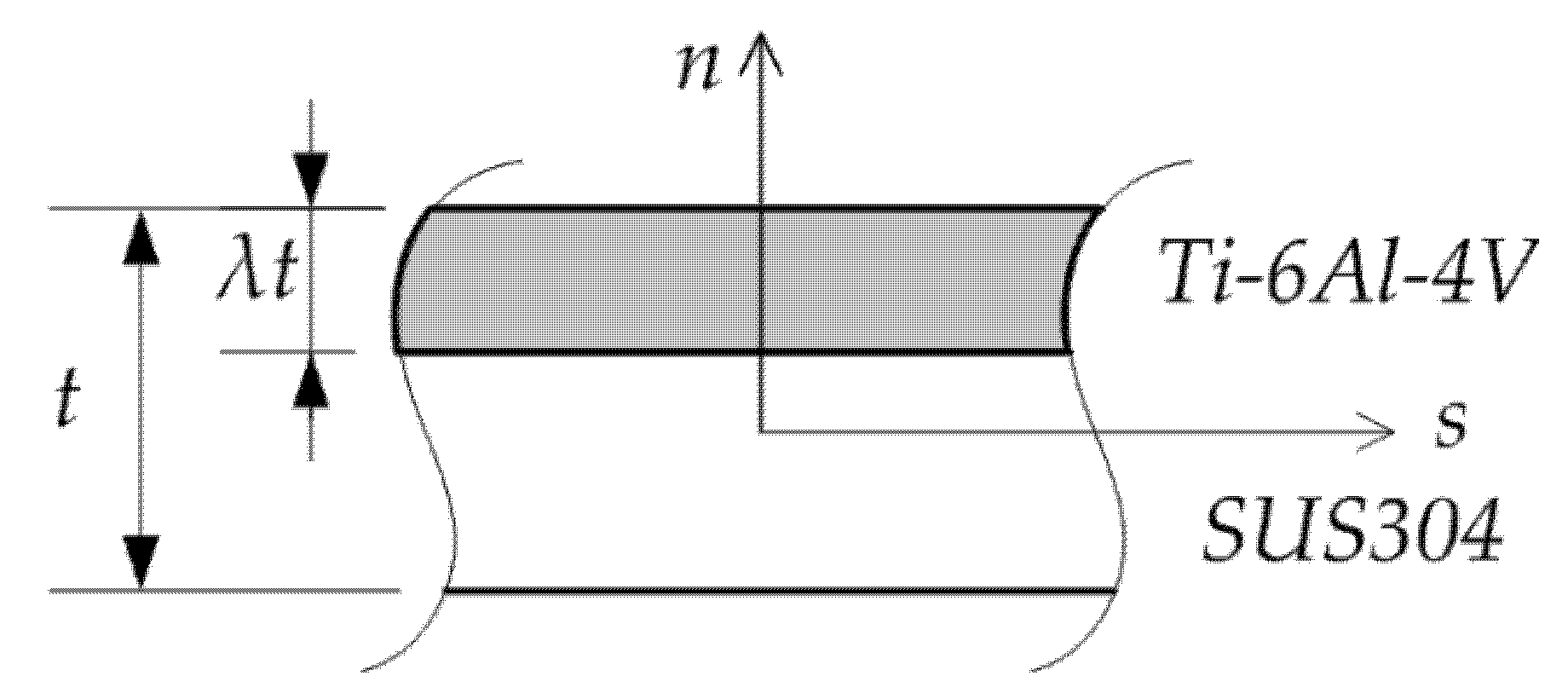
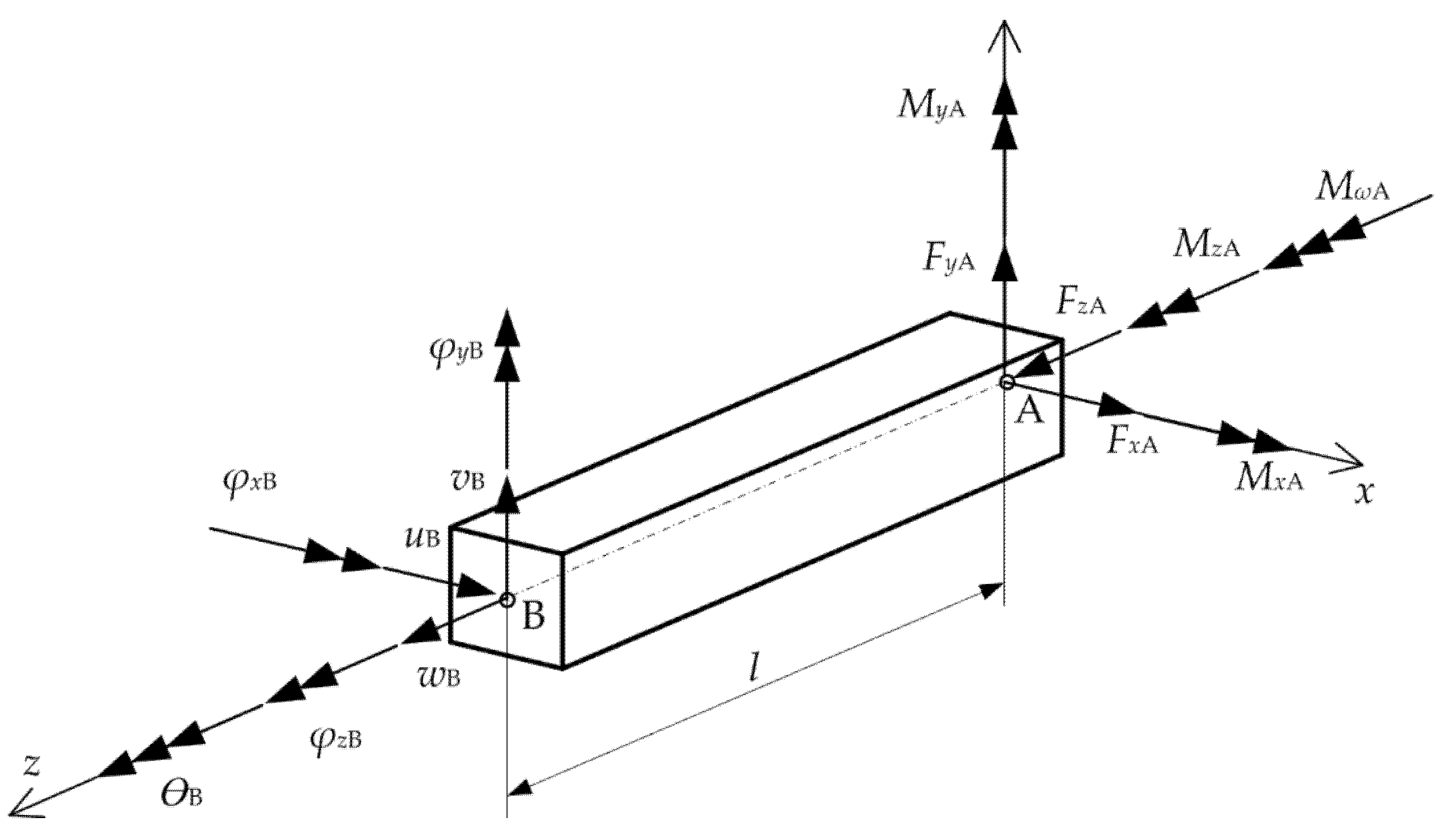
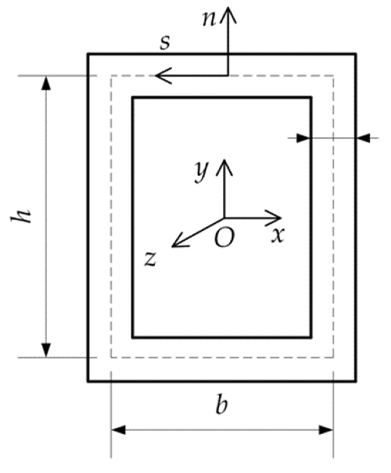
2.1. Kinematics
2.2. Constitutive Equations
2.3. Finite Element Formulation
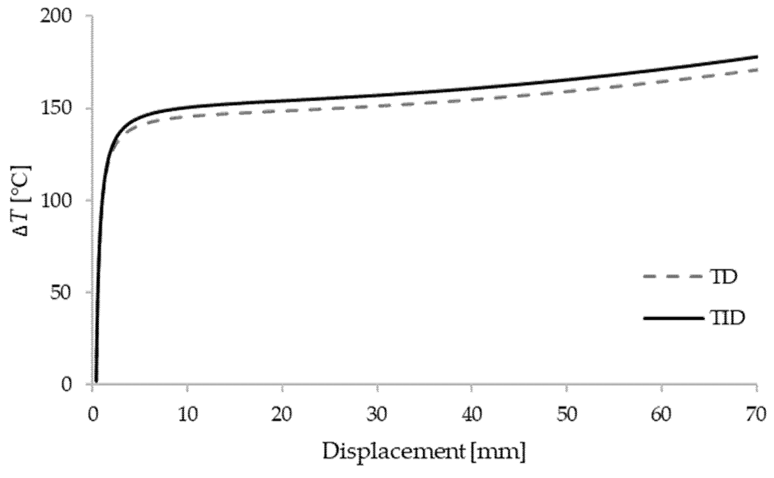
3. Results and Discussion
3.1. Box Beam
3.2. L-Frame
4. Conclusions
Author Contributions
Funding
Institutional Review Board Statement
Informed Consent Statement
Data Availability Statement
Acknowledgments
Conflicts of Interest
Appendix A
References
- Trahair, N.S. Flexural-Torsional Buckling of Structures; CRC Press: Boca Raton, FL, USA, 1993. [Google Scholar]
- Alfutov, N.A. Stability of Elastic Structures; Springer: Berlin/Heidelberg, Germany, 2000. [Google Scholar]
- Bin Kamarudin, M.N.; Mohamed Ali, J.S.; Aabid, A.; Ibrahim, Y.E. Buckling Analysis of a Thin-Walled Structure Using Finite Element Method and Design of Experiments. Aerospace 2022, 9, 541. [Google Scholar] [CrossRef]
- Turkalj, G.; Brnić, J. Nonlinear Stability Analysis of Thin-Walled Frames Using Ul–Esa Formulation. Int. J. Struct. Stab. Dyn. 2004, 4, 45–67. [Google Scholar] [CrossRef]
- Nguyen, N.D.; Vo, T.P.; Nguyen, T.K. An Improved Shear Deformable Theory for Bending and Buckling Response of Thin-Walled FG Sandwich I-Beams Resting on the Elastic Foundation. Compos. Struct. 2020, 254, 112823. [Google Scholar] [CrossRef]
- Pagani, A.; Augello, R.; Carrera, E. Frequency and Mode Change in the Large Deflection and Post-Buckling of Compact and Thin-Walled Beams. J. Sound Vib. 2018, 432, 88–104. [Google Scholar] [CrossRef]
- Lanc, D.; Turkalj, G.; Vo, T.P.; Brnić, J. Nonlinear Buckling Behaviours of Thin-Walled Functionally Graded Open Section Beams. Compos. Struct. 2016, 152, 829–839. [Google Scholar] [CrossRef]
- Lanc, D.; Vo, T.P.; Turkalj, G.; Lee, J. Buckling Analysis of Thin-Walled Functionally Graded Sandwich Box Beams. Thin-Walled Struct. 2015, 86, 148–156. [Google Scholar] [CrossRef]
- Banat, D.; Mania, R.J.; Degenhardt, R. Stress State Failure Analysis of Thin-Walled GLARE Composite Members Subjected to Axial Loading in the Post-Buckling Range. Compos. Struct. 2022, 289, 115468. [Google Scholar] [CrossRef]
- Nguyen, T.-T.; Kim, N.-I.; Lee, J. Analysis of Thin-Walled Open-Section Beams with Functionally Graded Materials. Compos. Struct. 2016, 138, 75–83. [Google Scholar] [CrossRef]
- Nguyen, T.; Lee, J. Optimal Design of Thin-Walled Functionally Graded Beams for Buckling Problems. Compos. Struct. 2017, 179, 459–467. [Google Scholar] [CrossRef]
- Jin, M.X.; Xiang, D.Z. Thermally-Induced Bending-Torsion Coupling Vibration of Large Scale Space Structures. Comput. Mech. 2007, 40, 707–723. [Google Scholar] [CrossRef]
- Saha, S. Thermal Buckling and Postbuckling Characteristics of Extensional Slender Elastic Rods. J. Mech. Eng. 2009, 40, 1–8. [Google Scholar] [CrossRef][Green Version]
- Cui, D.F.; Hu, H.Y. Thermal Buckling and Natural Vibration of the Beam with an Axial Stick—Slip—Stop Boundary. J. Sound Vib. 2014, 333, 2271–2282. [Google Scholar] [CrossRef]
- George, N.; Jeyaraj, P.; Murigendrappa, S.M. Thin-Walled Structures Buckling of Non-Uniformly Heated Isotropic Beam: Experimental and Theoretical Investigations. Thin Walled Struct. 2016, 108, 245–255. [Google Scholar] [CrossRef]
- Burgreen, D.; Manitt, P.J. Thermal Buckling of a Bimetallic Beams. J. Eng. Mech. Div. 1969, 95, 421–432. [Google Scholar] [CrossRef]
- Burgreen, D.; Regal, D. Higher Mode Buckling of Bimetallic Beam. J. Eng. Mech. Div. 1971, 97, 1045–1056. [Google Scholar] [CrossRef]
- Aydogdu, M. Thermal Buckling Analysis of Cross-Ply Laminated Composite Beams with General Boundary Conditions. Compos. Sci. Technol. 2007, 67, 1096–1104. [Google Scholar] [CrossRef]
- Trinh, L.C.; Vo, T.P.; Thai, H.T.; Nguyen, T.K. An Analytical Method for the Vibration and Buckling of Functionally Graded Beams under Mechanical and Thermal Loads. Compos. Part B Eng. 2016, 100, 152–163. [Google Scholar] [CrossRef]
- Kiani, Y.; Eslami, M.R. Thermal Buckling Analysis of Functionally Graded Material Beams. Int. J. Mech. Mater. Des. 2010, 6, 229–238. [Google Scholar] [CrossRef]
- Kiani, Y.; Eslami, M. Thermomechanical Buckling Dependent FGM Beams Of. Lat. Am. J. Solids Struct. 2013, 10, 223–246. [Google Scholar] [CrossRef]
- Giunta, G.; Crisafulli, D.; Belouettar, S.; Carrera, E. A Thermo-Mechanical Analysis of Functionally Graded Beams via Hierarchical Modelling. Compos. Struct. 2013, 95, 676–690. [Google Scholar] [CrossRef]
- Librescu, L.; Oh, S.Y.; Song, O. Thin-Walled Beams Made of Functionally Graded Materials and Operating in a High Temperature Environment: Vibration and Stability. J. Therm. Stress. 2005, 28, 649–712. [Google Scholar] [CrossRef]
- Ziane, N.; Meftah, S.A.; Ruta, G.; Tounsi, A. Thermal Effects on the Instabilities of Porous FGM Box Beams. Eng. Struct. 2017, 134, 150–158. [Google Scholar] [CrossRef]
- Kvaternik Simonetti, S.; Turkalj, G.; Lanc, D. Thin-Walled Structures Thermal Buckling Analysis of Thin-Walled Closed Section FG Beam-Type Structures. Thin-Walled Struct. 2022, 181, 110075. [Google Scholar] [CrossRef]
- Gjelsvik, A. The Theory of Thin-Walled Bars; Wiley: New York, NY, USA, 1981. [Google Scholar]
- Shen, H.S.; Wang, Z.X. Nonlinear Analysis of Shear Deformable FGM Beams Resting on Elastic Foundations in Thermal Environments. Int. J. Mech. Sci. 2014, 81, 195–206. [Google Scholar] [CrossRef]
- Reddy, J.N.; Chin, C.D. Thermomechanical Analysis of Functionally Graded Cylinders and Plates. J. Therm. Stress. 1998, 21, 593–626. [Google Scholar] [CrossRef]
- Turkalj, G.; Brnic, J.; Kravanja, S. A Beam Model for Large Displacement Analysis of Flexibly Connected Thin-Walled Beam-Type Structures. Thin-Walled Struct. 2011, 49, 1007–1016. [Google Scholar] [CrossRef]
- Bathe, K.J. Finite Element Procedure; Klaus-Jurgen Bathe, 2007. Available online: https://www.amazon.com/Finite-Element-Procedures-K-J-Bathe/dp/097900490X (accessed on 27 September 2022).
- Turkalj, G.; Brnic, J.; Prpic-Orsic, J. Large Rotation Analysis of Elastic Thin-Walled Beam-Type Structures Using ESA Approach. Comput. Struct. 2003, 81, 1851–1864. [Google Scholar] [CrossRef]
- Ansys Mechanical; Release 18.1; Help System. ANSYS, Inc.: Canonsburg, PA, USA. Available online: https://www.ansys.com/academic/terms-and-conditions (accessed on 27 September 2022).


| Material | Properties | P0 | P1 | P1 | P2 | P3 |
|---|---|---|---|---|---|---|
| Ti–6Al–4V | E (Pa) | 122.56 × 10⁹ | 0.0 | −4.586 × 10⁻⁴ | 0.0 | 0.0 |
| α (1/K) | 7.5788 × 10⁻⁶ | 0.0 | 6.638 × 10⁻⁴ | –3.147 × 10⁻⁶ | 0.0 | |
| SUS304 | E (Pa) | 201.04 × 10⁹ | 0.0 | 3.079 × 10⁻⁴ | –6.534 × 10⁻⁷ | 0.0 |
| α (1/K) | 12.330 × 10⁻⁶ | 0.0 | 8.086 × 10⁻⁴ | 0.0 | 0.0 |
| λ | |||||||||
|---|---|---|---|---|---|---|---|---|---|
| BC | Mode | Method | 0 | 0.2 | 0.4 | 0.5 | 0.6 | 0.8 | 1 |
| C-C | Y | Present | 128.87 | 135.26 | 145.83 | 153.64 | 164.09 | 199.19 | 284.51 |
| Shell | 130.22 | 138.77 | 151.18 | 159.72 | 170.71 | 205.83 | 287.97 | ||
| X | Present | 239.24 | 252.56 | 273.89 | 288.9 | 308.62 | 373.43 | 528.16 | |
| Shell | 238.95 | 254.69 | 277.45 | 293.11 | 313.24 | 377.6 | 527.52 | ||
| C-S | Y | Present | 66.58 | 69.91 | 75.39 | 79.44 | 84.84 | 102.97 | 146.98 |
| Shell | 65.98 | 70.313 | 76.604 | 80.936 | 86.504 | 104.29 | 145.66 | ||
| X | Present | 122.87 | 130.02 | 140.09 | 148.58 | 158.73 | 192.03 | 271.48 | |
| Shell | 120.46 | 128.39 | 139.88 | 147.78 | 157.93 | 190.37 | 265.92 | ||
| S-S | Y | Present | 32.72 | 34.368 | 37.07 | 39.06 | 41.72 | 50.62 | 72.24 |
| Shell | 32.196 | 34.314 | 37.39 | 39.507 | 42.226 | 50.904 | 71.077 | ||
| X | Present | 60.28 | 60.29 | 69.07 | 72.86 | 77.83 | 94.15 | 133.08 | |
| Shell | 58.725 | 62.6 | 68.208 | 72.063 | 77.015 | 92.827 | 129.64 | ||
| λ | |||||||||
|---|---|---|---|---|---|---|---|---|---|
| BC | Mode | Method | 0 | 0.2 | 0.4 | 0.5 | 0.6 | 0.8 | 1 |
| C-C | Y | Present | 73.17 | 76.83 | 82.85 | 87.3 | 93.24 | 113.16 | 161.54 |
| Shell | 73.542 | 78.368 | 85.375 | 90.2 | 96.405 | 116.24 | 162.35 | ||
| X | Present | 135.52 | 142.96 | 154.88 | 163.38 | 174.53 | 211.15 | 298.53 | |
| Shell | 135.02 | 143.91 | 156.78 | 165.62 | 177 | 213.37 | 298.08 | ||
| C-S | Y | Present | 37.63 | 39.52 | 42.63 | 44.91 | 47.97 | 58.21 | 83.07 |
| Shell | 37.323 | 39.774 | 43.33 | 45.783 | 48.933 | 58.997 | 82.396 | ||
| X | Present | 69.35 | 73.33 | 79.45 | 83.81 | 89.53 | 108.31 | 153.09 | |
| Shell | 68.256 | 72.754 | 79.261 | 83.736 | 89.487 | 107.87 | 150.68 | ||
| S-S | Y | Present | 18.45 | 19.38 | 20.9 | 22.03 | 23.53 | 28.55 | 40.73 |
| Shell | 18.211 | 19.409 | 21.149 | 22.346 | 23.885 | 28.793 | 40.204 | ||
| X | Present | 33.95 | 35.9 | 38.9 | 41.04 | 43.84 | 53.03 | 74.95 | |
| Shell | 33.278 | 35.473 | 38.651 | 40.836 | 43.642 | 52.603 | 73.466 | ||
| λ | |||||||||
|---|---|---|---|---|---|---|---|---|---|
| BC | Mode | Method | 0 | 0.2 | 0.4 | 0.5 | 0.6 | 0.8 | 1 |
| C-C | Y | Present | 47.03 | 49.39 | 53.27 | 56.13 | 59.95 | 72.75 | 103.83 |
| Shell | 47.158 | 50.252 | 54.745 | 57.839 | 61.818 | 74.536 | 104.11 | ||
| X | Present | 86.74 | 91.72 | 99.37 | 104.82 | 111.98 | 135.47 | 191.49 | |
| Shell | 86.605 | 92.308 | 100.56 | 106.23 | 113.53 | 136.86 | 191.19 | ||
| C-S | Y | Present | 24.14 | 25.35 | 27.35 | 28.81 | 30.77 | 37.34 | 53.28 |
| Shell | 23.965 | 25.538 | 27.823 | 29.397 | 31.419 | 37.881 | 52.906 | ||
| X | Present | 44.43 | 46.99 | 50.91 | 53.71 | 57.38 | 69.4 | 98.09 | |
| Shell | 43.872 | 46.763 | 50.945 | 53.822 | 57.518 | 69.335 | 96.854 | ||
| S-S | Y | Present | 11.82 | 12.42 | 13.39 | 14.11 | 15.07 | 18.29 | 26.09 |
| Shell | 11.695 | 12.464 | 13.582 | 14.35 | 15.338 | 18.491 | 25.818 | ||
| X | Present | 21.74 | 22.99 | 24.91 | 26.28 | 28.08 | 33.96 | 47.99 | |
| Shell | 21.396 | 22.807 | 24.85 | 26.255 | 28.059 | 33.82 | 47.234 | ||
Publisher’s Note: MDPI stays neutral with regard to jurisdictional claims in published maps and institutional affiliations. |
© 2022 by the authors. Licensee MDPI, Basel, Switzerland. This article is an open access article distributed under the terms and conditions of the Creative Commons Attribution (CC BY) license (https://creativecommons.org/licenses/by/4.0/).
Share and Cite
Simonetti, S.K.; Turkalj, G.; Banić, D.; Lanc, D. Bimetallic Thin-Walled Box Beam Thermal Buckling Response. Materials 2022, 15, 7537. https://doi.org/10.3390/ma15217537
Simonetti SK, Turkalj G, Banić D, Lanc D. Bimetallic Thin-Walled Box Beam Thermal Buckling Response. Materials. 2022; 15(21):7537. https://doi.org/10.3390/ma15217537
Chicago/Turabian StyleSimonetti, Sandra Kvaternik, Goran Turkalj, Damjan Banić, and Domagoj Lanc. 2022. "Bimetallic Thin-Walled Box Beam Thermal Buckling Response" Materials 15, no. 21: 7537. https://doi.org/10.3390/ma15217537
APA StyleSimonetti, S. K., Turkalj, G., Banić, D., & Lanc, D. (2022). Bimetallic Thin-Walled Box Beam Thermal Buckling Response. Materials, 15(21), 7537. https://doi.org/10.3390/ma15217537