

Experiments and Modeling of Machined Spring Rotary Actuators with Shape Memory Alloys

 ,
,
Abstract
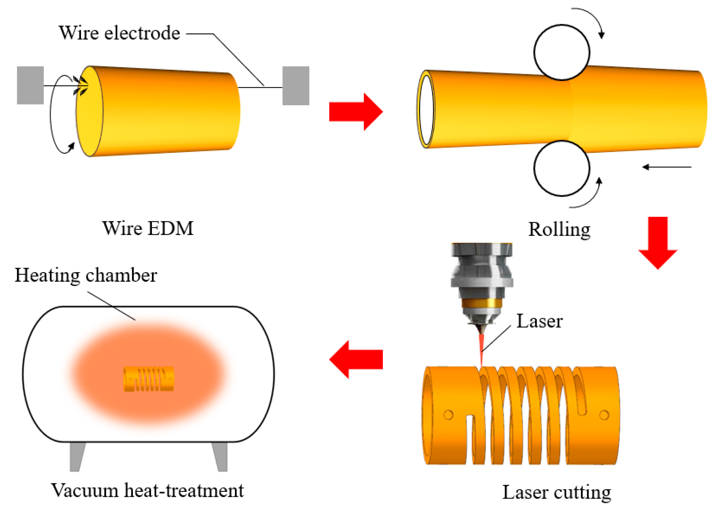
:1. Introduction
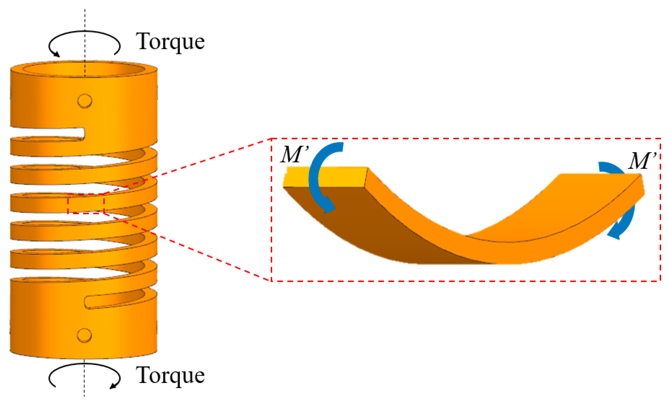
2. Analytical Model of the SMAMS
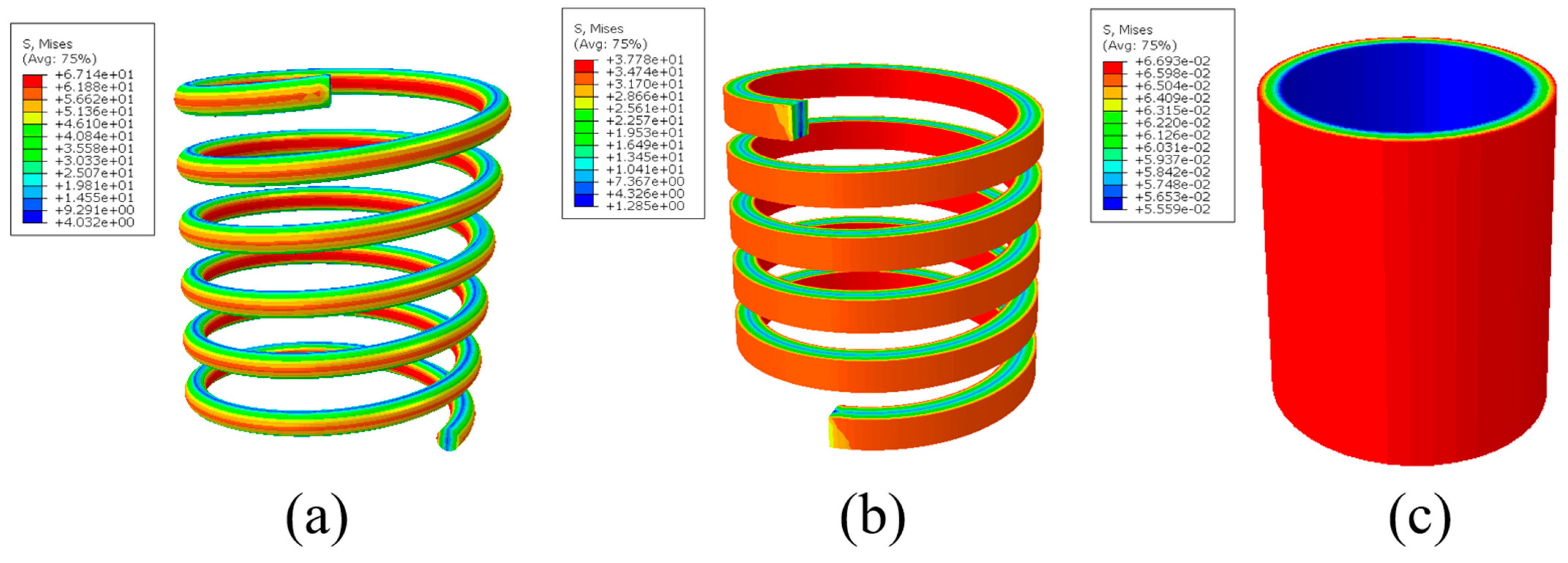
3. Finite Element Analysis of the SMAMS
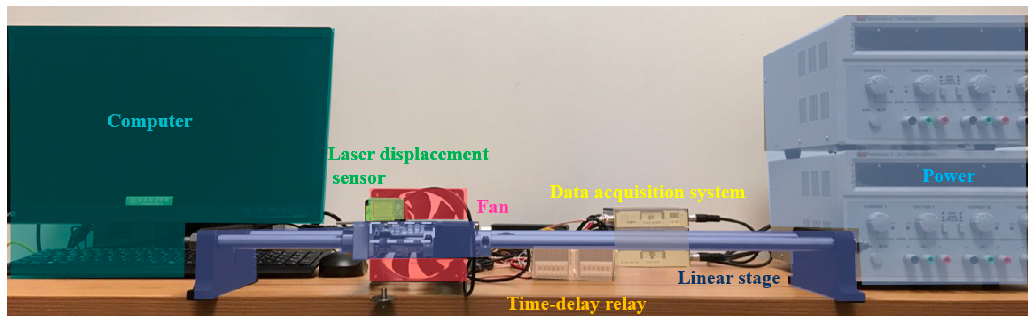
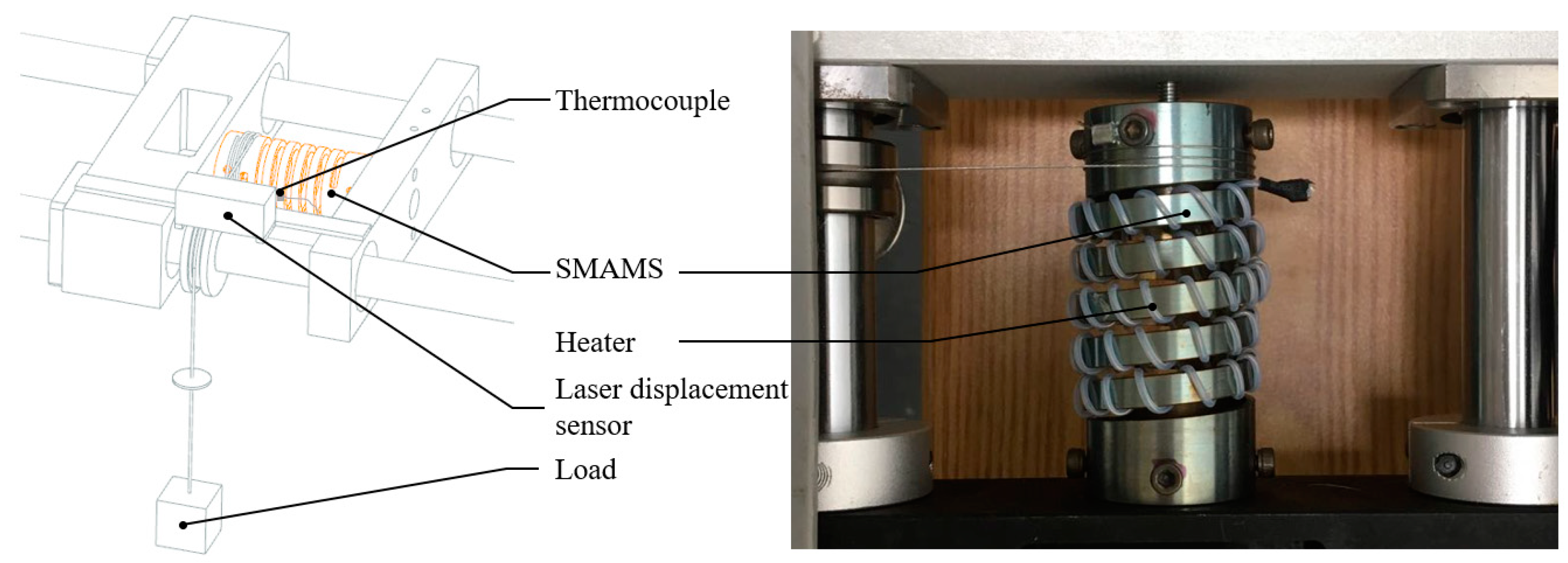
4. Experimental Validation
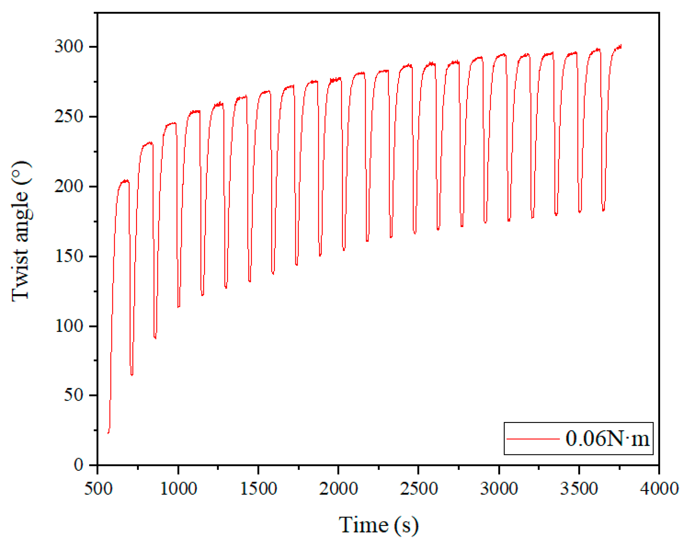
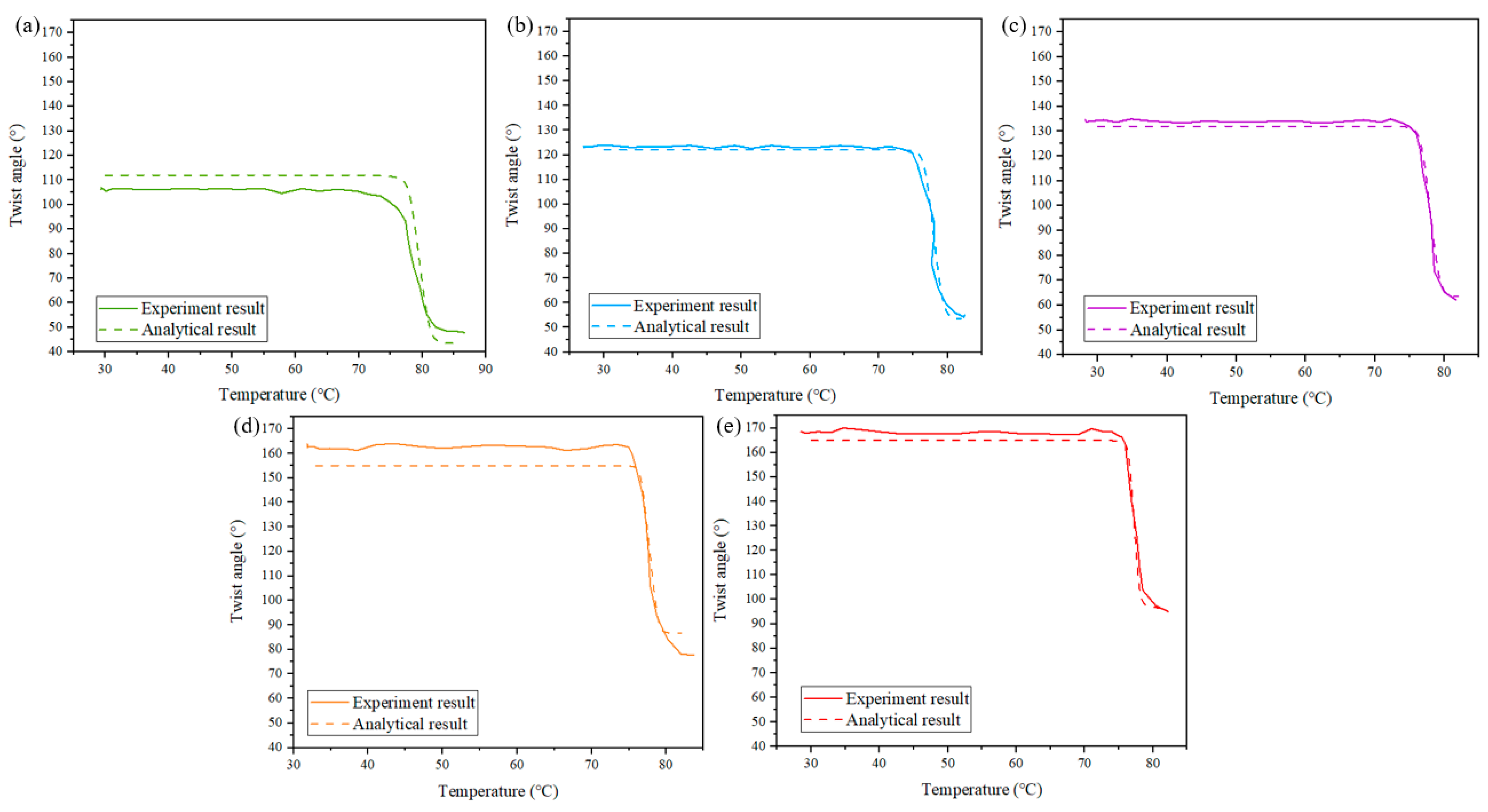
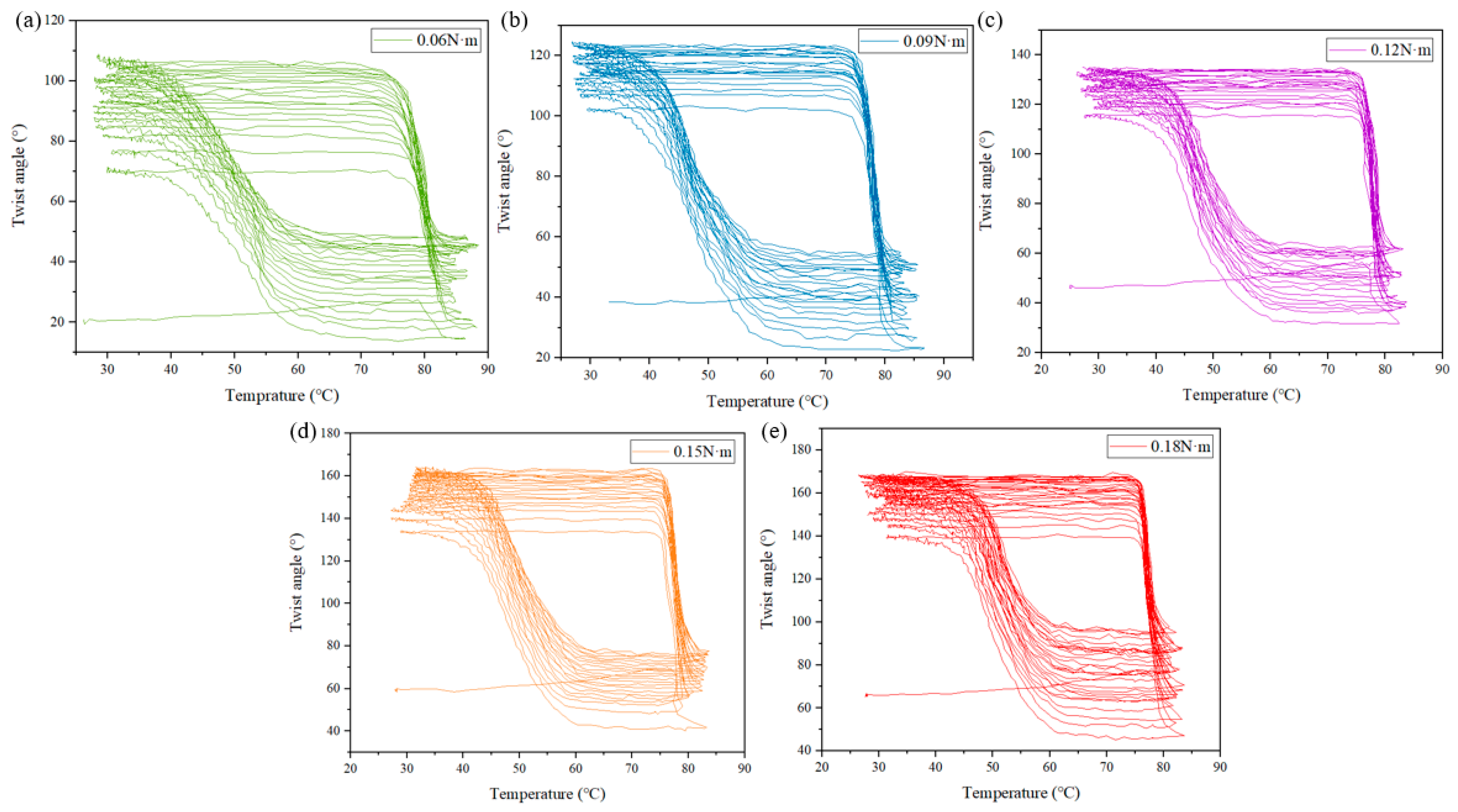
Thermomechanical Response
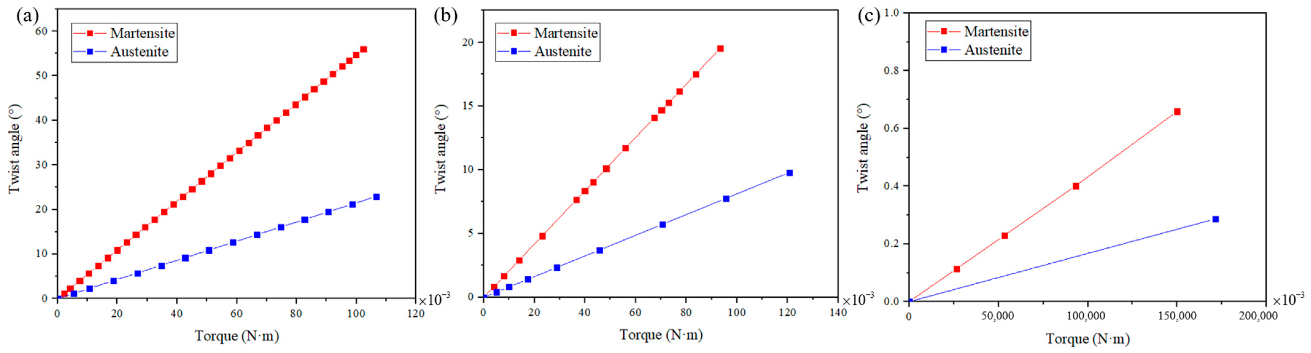
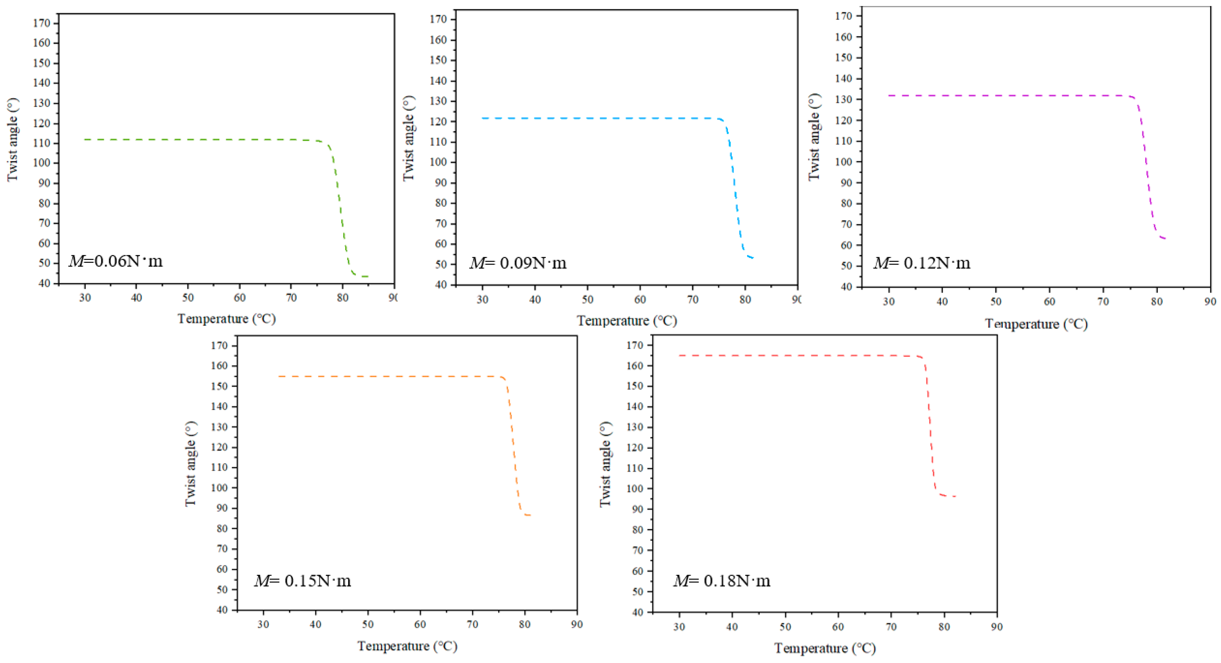
5. Results and Discussions
6. Conclusions
- (1)
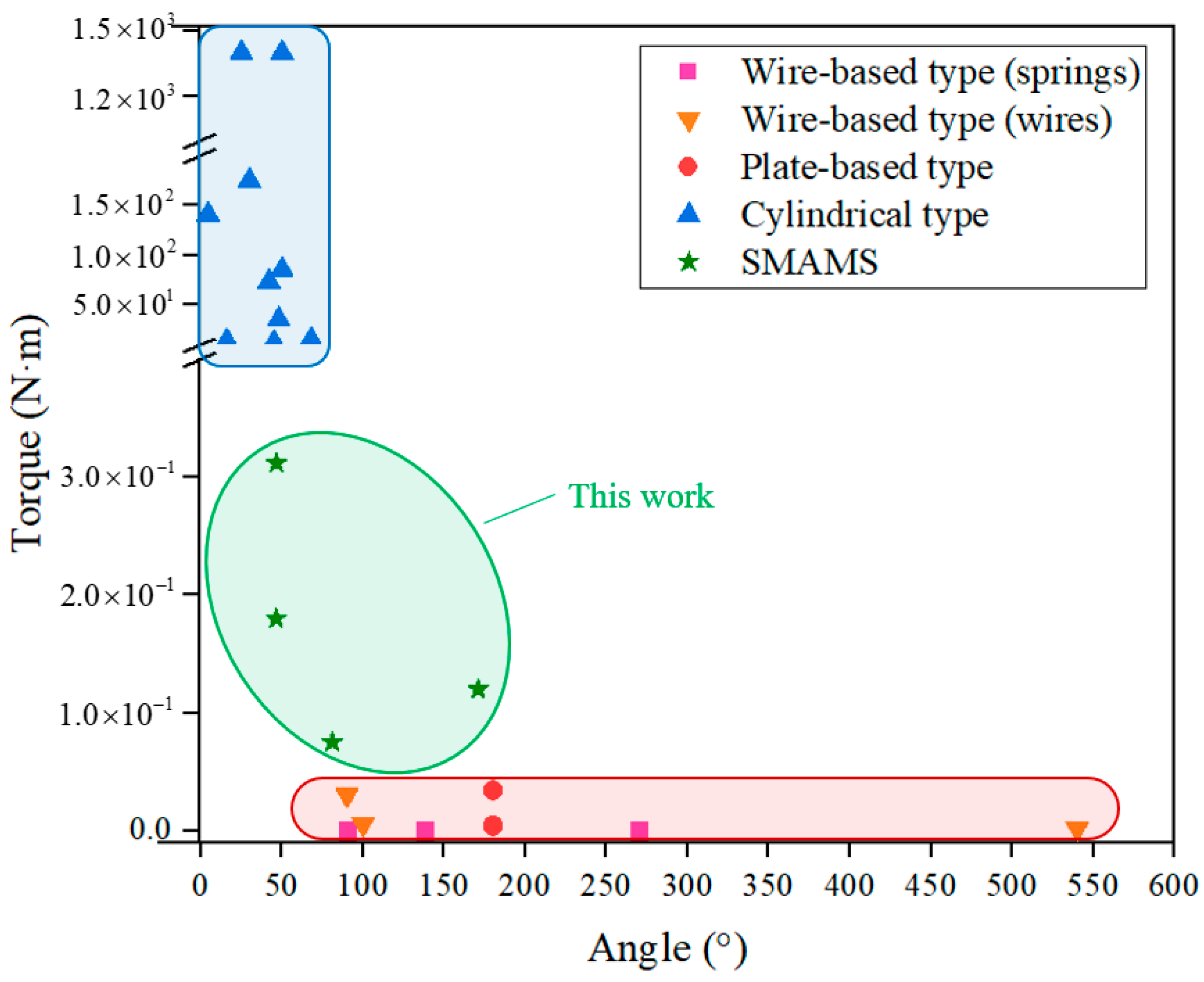
- The SMAMS can be designed to have a larger twist angle than the tube and to bear a larger torque than the spring of the circular cross-section, provided that the inner and outer diameter remains unchanged, which fills the gap between wire-based-type rotary actuators and cylindrical-type rotary actuators.
- (2)
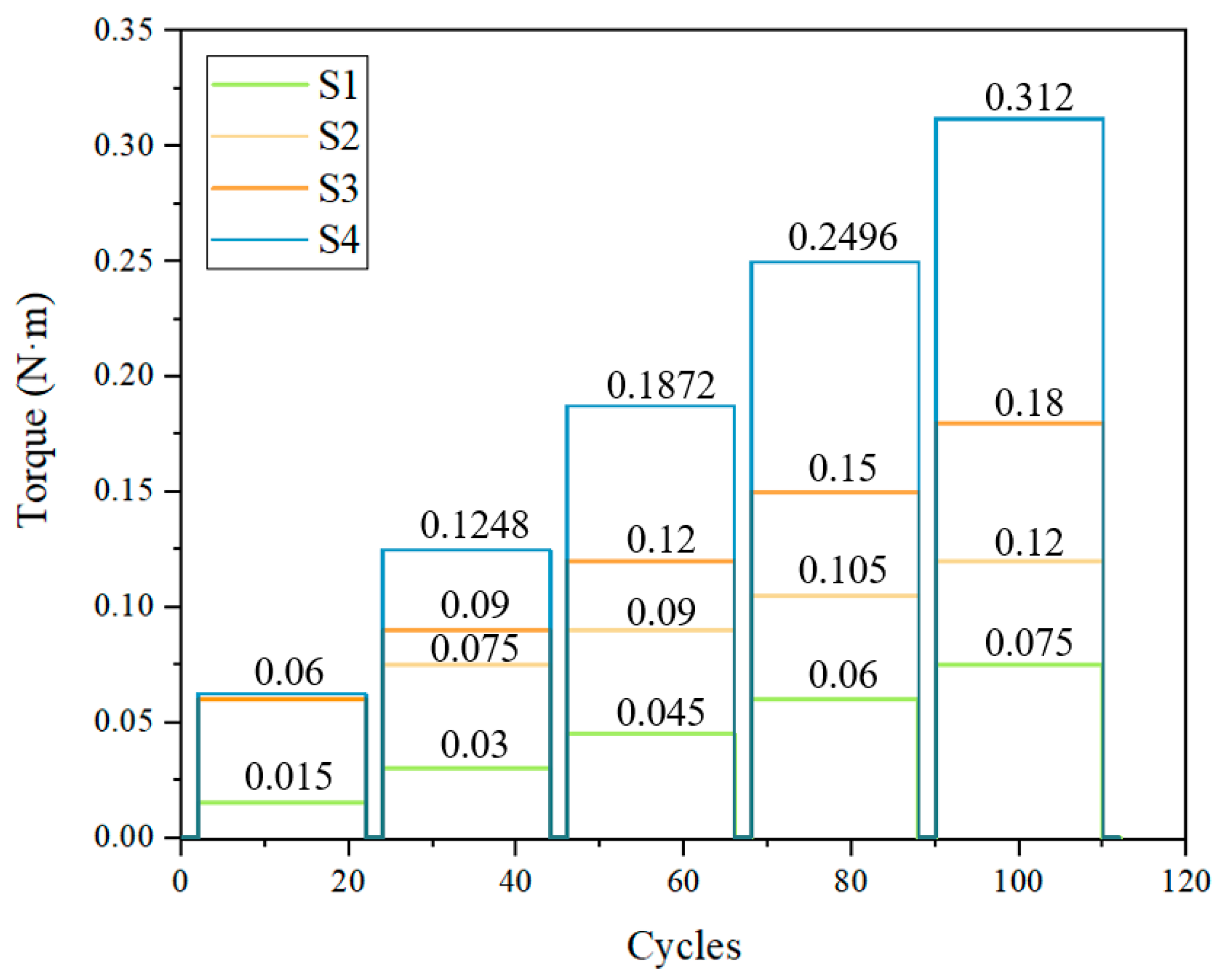
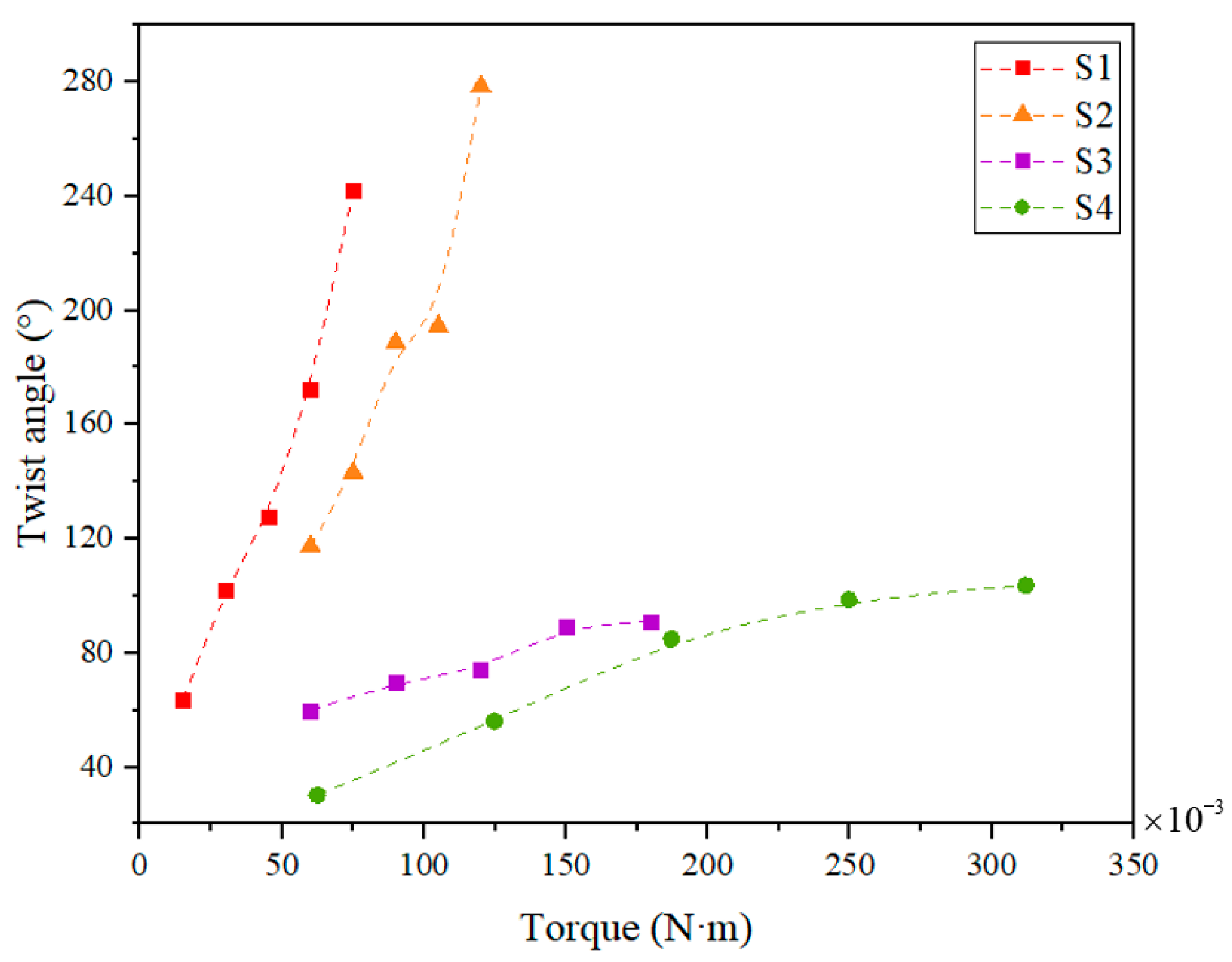
- The twist angle of the SMAMS gradually increases with the applied torque. Specifically, the twist angle of S2 ranges from 117.3° at a torque of 0.06 N·m to 278.5° at 0.12 N·m; S4 ranges from 30.2° at a torque of 0.0624 N·m to 103.6° at 0.312 N·m.
- (3)
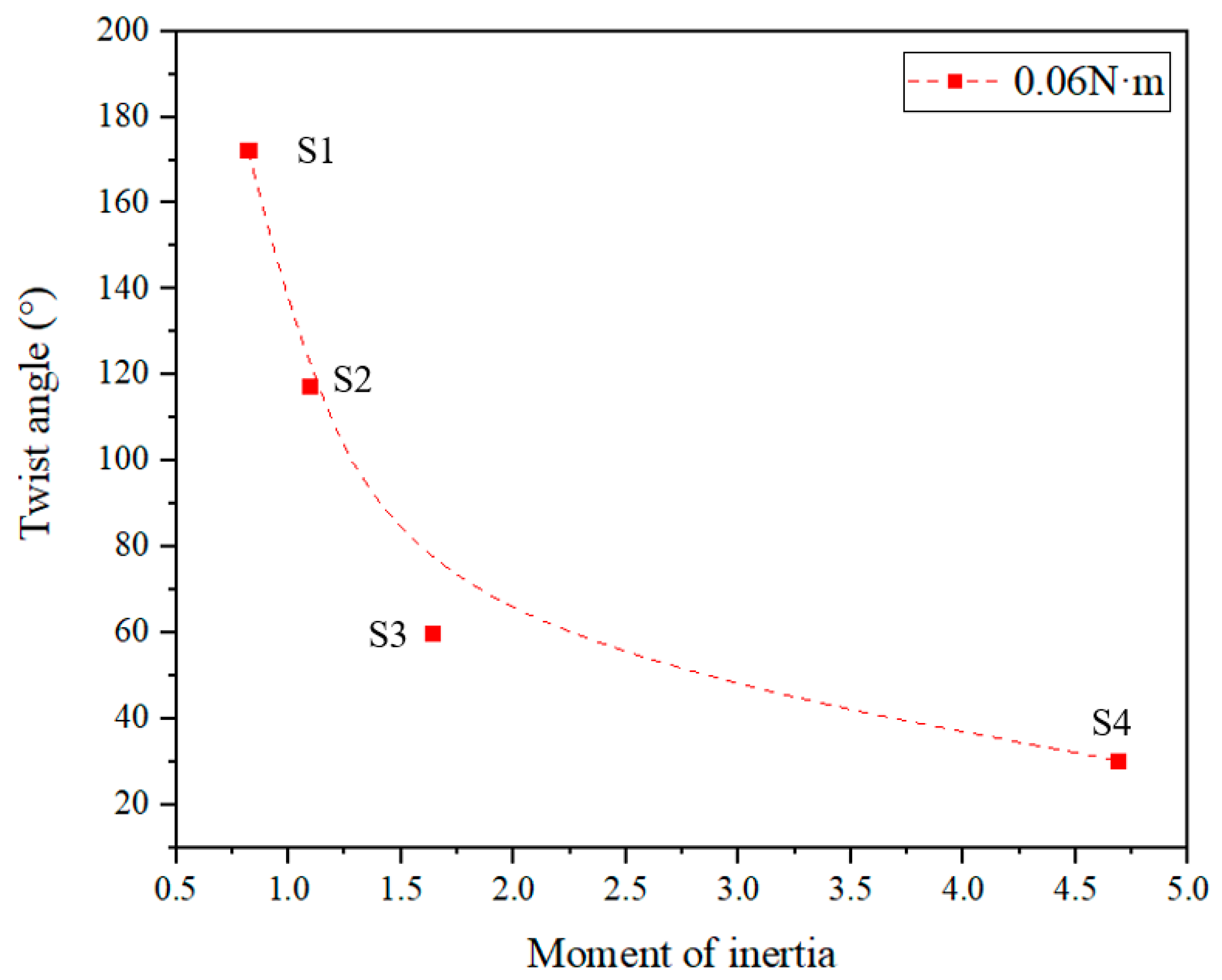
- The twist angle of SMAMSs decreases as the moment of inertia increases under a constant applied torque.
- (4)
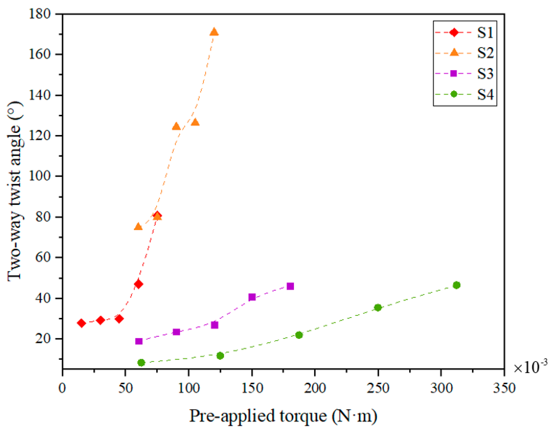
- The two-way twist angle of SMAMSs decreases as the pre-applied torque increases. Specifically, the two-way twist angle of S2 ranges from 75° at a pre-applied torque of 0.06 N·m to 171° at 0.12 N·m; S4 ranges from 8.4° at a pre-applied torque of 0.0624 N·m to 46.6° at 0.312 N·m.
Author Contributions
Funding
Institutional Review Board Statement
Data Availability Statement
Conflicts of Interest
References
- Scarpino, M. Motors for Makers: A Guide to Steppers, Servos, and Other Electrical Machines; Que Publishing: London, UK, 2015. [Google Scholar]
- Jani, J.M.; Leary, M.; Subic, A.; Gibson, M.A. A review of shape memory alloy research, applications and opportunities. Mater. Des. 2014, 56, 1078–1113. [Google Scholar] [CrossRef]
- Benafan, O.; Gaydosh, D.J. Machined helical springs from NiTiHf shape memory alloy. Smart Mater. Struct. 2020, 29, 125001. [Google Scholar] [CrossRef]
- Chen, Y.; Rios, C.O.; McLain, B.; Newkirk, J.W.; Liou, F. TiNi-Based Bi-Metallic Shape-Memory Alloy by Laser-Directed Energy Deposition. Materials 2022, 15, 3945. [Google Scholar] [CrossRef]
- Vora, J.; Jain, A.; Sheth, M.; Gajjar, K.; Abhishek, K.; Chaudhari, R. A Review on Machining Aspects of Shape Memory Alloys. In Recent Advances in Mechanical Infrastructure; Parwani, A.K., Ramkumar, P.L., Abhishek, K., Yadav, S.K., Eds.; Springer Nature: Singapore, 2022; pp. 449–458. [Google Scholar]
- Jani, J.M.; Leary, M.; Subic, A. Designing shape memory alloy linear actuators: A review. J. Intell. Mater. Syst. Struct. 2016, 28, 1699–1718. [Google Scholar] [CrossRef]
- Rajput, G.S.; Vora, J.; Prajapati, P.; Chaudhari, R. Areas of recent developments for shape memory alloy: A review. Mater. Today Proc. 2022, 62, 7194–7198. [Google Scholar] [CrossRef]
- Zhu, L.; Liu, Y.; Li, M.; Lu, X.; Zhu, X. Calculation Model of Mechanical and Sealing Properties of NiTi Alloy Corrugated Gaskets under Shape Memory Effect and Hyperelastic Coupling: I Mechanical Properties. Materials 2022, 15, 4836. [Google Scholar] [CrossRef] [PubMed]
- Stroud, H.; Hartl, D. Shape memory alloy torsional actuators: A review of applications, experimental investigations, modeling, and design. Smart Mater. Struct. 2020, 29, 113001. [Google Scholar] [CrossRef]
- Yuan, H.; Fauroux, J.C.; Chapelle, F.; Balandraud, X. A review of rotary actuators based on shape memory alloys. J. Intell. Mater. Syst. Struct. 2017, 28, 1863–1885. [Google Scholar] [CrossRef]
- Nespoli, A.; Bassani, E.; Besseghini, S.; Villa, E. Rotational mini-actuator activated by two antagonist shape memory alloy wires. Phys. Procedia 2010, 10, 182–188. [Google Scholar] [CrossRef]
- Song, G. Design and control of a Nitinol wire actuated rotary servo. Smart Mater. Struct. 2007, 16, 1796–1801. [Google Scholar] [CrossRef]
- Zhang, X.Y.; Yan, X.J. Continuous Rotary Motor Actuated by Multiple Segments of Shape Memory Alloy Wires. J. Mater. Eng. Perform. 2012, 21, 2643–2649. [Google Scholar] [CrossRef]
- Spinella, I.; Mammano, G.S.; Dragoni, E. Conceptual Design and Simulation of a Compact Shape Memory Actuator for Rotary Motion. J. Mater. Eng. Perform. 2009, 18, 638–648. [Google Scholar] [CrossRef]
- JKoh, S.; Kim, S.R.; Cho, K.J. Self-Folding Origami Using Torsion Shape Memory Alloy Wire Actuators. In Proceedings of the ASME International Design Engineering Technical Conferences and Computers and Information in Engineering Conference, Buffalo, NY, USA, 17–20 August 2014; Volume 5. [Google Scholar]
- Wood, L.J.; Rendon, J.; Malak, R.J.; Hartl, D. An Origami-Inspired, Sma Actuated Lifting Structure. In Proceedings of the ASME International Design Engineering Technical Conferences and Computers and Information in Engineering Conference, Charlotte, CA, USA, 21–24 August 2016; Volume 5. [Google Scholar]
- Sheng, J.; Desai, J.P. Design, Modeling and Characterization of A Novel Meso-Scale SMA-Actuated Torsion Actuator. Smart Mater. Struct. 2015, 24, 105005. [Google Scholar] [CrossRef] [PubMed]
- Yan, X.; Huang, D.; Zhang, X. Note: A novel curvature-driven shape memory alloy torsional actuator. Rev. Sci. Instrum. 2014, 85, 126109. [Google Scholar] [CrossRef] [PubMed]
- Yuan, H.; Balandraud, X.; Fauroux, J.C.; Chapelle, F. Compliant Rotary Actuator Driven by Shape Memory Alloy. In New Advances in Mechanisms, Mechanical Transmissions and Robotics; Springer: Berlin/Heidelberg, Germany, 2017; pp. 343–350. [Google Scholar]
- Paik, J.K.; Hawkes, E.; Wood, R.J. A novel low-profile shape memory alloy torsional actuator. Smart Mater. Struct. 2010, 19, 125014. [Google Scholar] [CrossRef]
- Paik, J.K.; Wood, R.J. A bidirectional shape memory alloy folding actuator. Smart Mater. Struct. 2012, 21, 065013. [Google Scholar] [CrossRef]
- Tobushi, H.; Pieczyska, E.; Miyamoto, K.; Mitsui, K. Torsional deformation characteristics of TiNi SMA tape and application to rotary actuator. J. Alloys Compd. 2013, 577, S745–S748. [Google Scholar] [CrossRef]
- Tobushi, H.; Pieczyska, E.A.; Nowacki, W.K.; Date, K.; Miyamoto, K. Two-Way Rotary Shape Memory Alloy Thin Strip Actuator. J. Theor. App. Mech. 2010, 48, 1043–1056. [Google Scholar]
- Zhakypov, Z.; Huang, J.-L.; Paik, J. A Novel Torsional Shape Memory Alloy Actuator: Modeling, Characterization, and Control. IEEE Robot. Autom. Mag. 2016, 23, 65–74. [Google Scholar] [CrossRef]
- Don, W.L.; Tom, M.R.; James, W.G.; James, J.A.; Chen, L.; Frank, M.D. Shape control of solar collectors using torsional shape memory alloy actuators. In Proceedings of the Smart Structures and Materials 1996: Industrial and Commercial Applications of Smart Structures Technologies, San Diego, CA, USA, 25 February 1996; Bellingham, WA, USA, 1996. [Google Scholar]
- Benafan, O.; Gaydosh, D.J. High temperature shape memory alloy Ni50.3Ti29.7Hf20torque tube actuators. Smart Mater. Struct. 2017, 26, 095002. [Google Scholar] [CrossRef]
- Benafan, O.; Gaydosh, D.J. Constant-torque thermal cycling and two-way shape memory effect in Ni50.3Ti29.7Hf20 torque tubes. Smart Mater. Struct. 2018, 27, 075035. [Google Scholar] [CrossRef] [PubMed]
- Benafan, O.; Gaydosh, D.J. Scale-up of NiTiHf shape memory alloy tubes with high torque capability. Smart Mater. Struct. 2019, 28, 085035. [Google Scholar] [CrossRef]
- Benafan, O.; Moholt, M.R.; Bass, M.; Mabe, J.H.; Nicholson, D.E.; Calkins, F.T. Recent Advancements in Rotary Shape Memory Alloy Actuators for Aeronautics. Shape Mem. Superelasticity 2019, 5, 415–428. [Google Scholar] [CrossRef]
- Icardi, U.; Ferrero, L. Preliminary study of an adaptive wing with shape memory alloy torsion actuators. Mater. Des. 2009, 30, 4200–4210. [Google Scholar] [CrossRef]
- Jardine, A.P.; Kudva, J.N.; Martin, C.; Appa, K. Shape memory alloy TiNi actuators for twist control of smart wing designs. Smart Struct. Integr. Syst. 1996, 2717, 160–165. [Google Scholar]
- Prahlad, H.; Chopra, I. Design of a variable twist tiltrotor blade using shape memory alloy (SMA) actuators. In Proceedings of the SPIE, Smart Structures and Materials, Newport Beach, CA, USA, 1–5 March 2001; Volume 4327, pp. 46–59. [Google Scholar]
- Stein, C.A.; Hartl, D.J.; Hodge, L.; Mabe, J.; Herrington, J.; Saunders, R. Development of a Twisting Wing Powered by a Shape Memory Alloy Actuator. In Proceedings of the 23rd AIAA/AHS Adaptive Structures Conference, Kissimmee, FL, USA, 5–9 January 2015. [Google Scholar]
- Shigley, J.E. Shigley’s Mechanical Engineering Design; Tata McGraw-Hill Education: New York, NY, USA, 2011. [Google Scholar]
- Brinson, L.C. One-Dimensional Constitutive Behavior of Shape Memory Alloys: Thermomechanical Derivation with Non-Constant Material Functions and Redefined Martensite Internal Variable. J. Intell. Mater. Syst. Struct. 1993, 4, 229–242. [Google Scholar] [CrossRef]
- Brinson, L.C.; Huang, M.S. Simplifications and Comparisons of Shape Memory Alloy Constitutive Models. J. Intell. Mater. Syst. Struct. 1996, 7, 108–114. [Google Scholar] [CrossRef]
- Liang, C.; Rogers, C.A. One-dimensional thermomechanical constitutive relations for shape memory materials. J. Intell. Mater. Syst. Struct. 1990, 1, 207–234. [Google Scholar] [CrossRef]
- Lagoudas, D.C.; Bo, Z.; Qidwai, M.A. A unified thermodynamic constitutive model for SMA and finite element analysis of active metal matrix composites. Mech. Compos. Mater. Struct. 1996, 3, 153–179. [Google Scholar] [CrossRef]
- Shim, J.-E.; Quan, Y.-J.; Wang, W.; Rodrigue, H.; Song, S.-H.; Ahn, S.-H. A smart soft actuator using a single shape memory alloy for twisting actuation. Smart Mater. Struct. 2015, 24, 125033. [Google Scholar] [CrossRef]


| Property | Symbol | Value |
|---|---|---|
| Young’s modulus (austenite-phase) | Da | 67 GPa |
| Young’s modulus (martensite-phase) | Dm | 26.3 GPa |
| Maximum residual strain | εL | 0.038 |
| Thermal expansion coefficient | Θ | 0.55 MPa/°C |
| Austenite-phase finish temperature | Af | 82 °C |
| Austenite-phase start temperature | As | 77 °C |
| Martensite-phase finish temperature | Mf | 40 °C |
| Martensite-phase start temperature | Ms | 58 °C |
| Stress influence coefficient for austenite | CA | 13.8 MPa/°C |
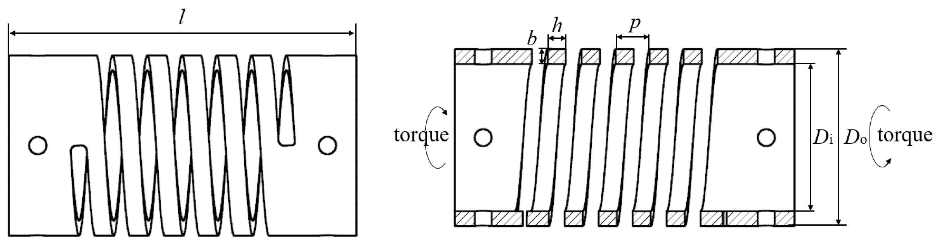
| Parameter | Symbol | S1 | S2 | S3 | S4 |
|---|---|---|---|---|---|
| Outer diameter | Do | 30 mm | 30 mm | 30 mm | 31.2 mm |
| Inner diameter | Di | 26.6 mm | 26.6 mm | 26.6 mm | 25.8 mm |
| Cross section ⊥ to spring axis | b | 1.6 mm | 1.6 mm | 1.6 mm | 2.6 mm |
| Cross section ∥ to spring axis | h | 2.4 mm | 3.2 mm | 4.8 mm | 3.2 mm |
| No. of active coils | n | 5 | 5 | 5 | 5 |
| Pitch | p | 6 mm | 6 mm | 6 mm | 6 mm |
| Overall length | l | 60 mm | 60 mm | 60 mm | 60 mm |
| Spring index | - | 17.68 | 17.68 | 17.68 | 10.96 |
Publisher’s Note: MDPI stays neutral with regard to jurisdictional claims in published maps and institutional affiliations. |
© 2022 by the authors. Licensee MDPI, Basel, Switzerland. This article is an open access article distributed under the terms and conditions of the Creative Commons Attribution (CC BY) license (https://creativecommons.org/licenses/by/4.0/).
Share and Cite
Chen, T.; Zhang, Y.; Qiu, S.; Jiang, J.; Zhang, Q.; Zhang, X. Experiments and Modeling of Machined Spring Rotary Actuators with Shape Memory Alloys. Materials 2022, 15, 6674. https://doi.org/10.3390/ma15196674
Chen T, Zhang Y, Qiu S, Jiang J, Zhang Q, Zhang X. Experiments and Modeling of Machined Spring Rotary Actuators with Shape Memory Alloys. Materials. 2022; 15(19):6674. https://doi.org/10.3390/ma15196674
Chicago/Turabian StyleChen, Tiegang, Yuhang Zhang, Shengbin Qiu, Jun Jiang, Qiang Zhang, and Xiaoyong Zhang. 2022. "Experiments and Modeling of Machined Spring Rotary Actuators with Shape Memory Alloys" Materials 15, no. 19: 6674. https://doi.org/10.3390/ma15196674
APA StyleChen, T., Zhang, Y., Qiu, S., Jiang, J., Zhang, Q., & Zhang, X. (2022). Experiments and Modeling of Machined Spring Rotary Actuators with Shape Memory Alloys. Materials, 15(19), 6674. https://doi.org/10.3390/ma15196674