
Body-Centered Double-Square Split-Ring Enclosed Nested Meander-Line-Shaped Metamaterial-Loaded Microstrip-Based Resonator for Sensing Applications

 , ,
, ,  , and
, and
Abstract
:1. Introduction
2. Metamaterial Incorporated Sensor Design and Method
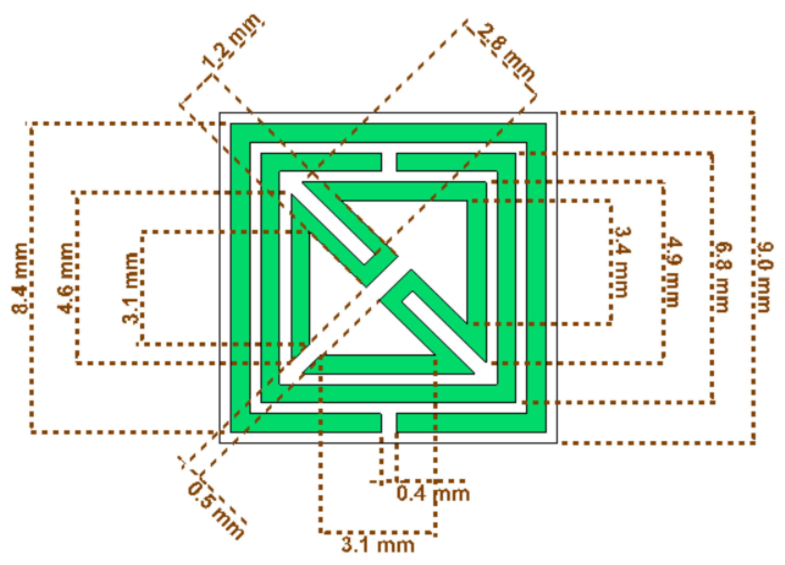
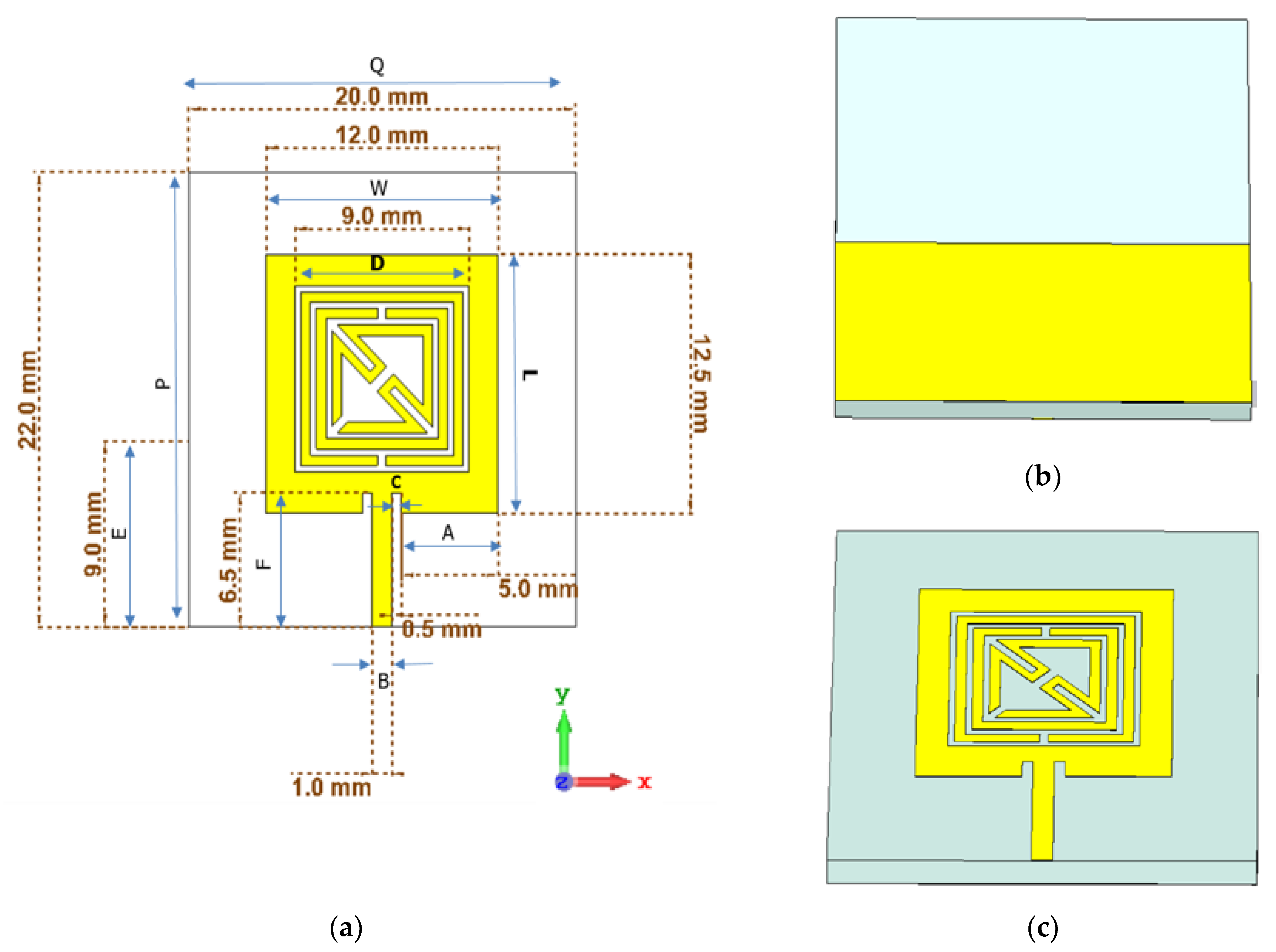
2.1. Metamaterial Unit Cell Design
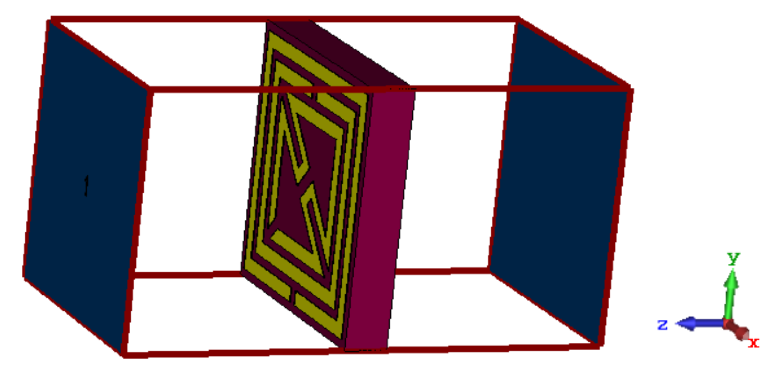
2.2. Boundary Condition
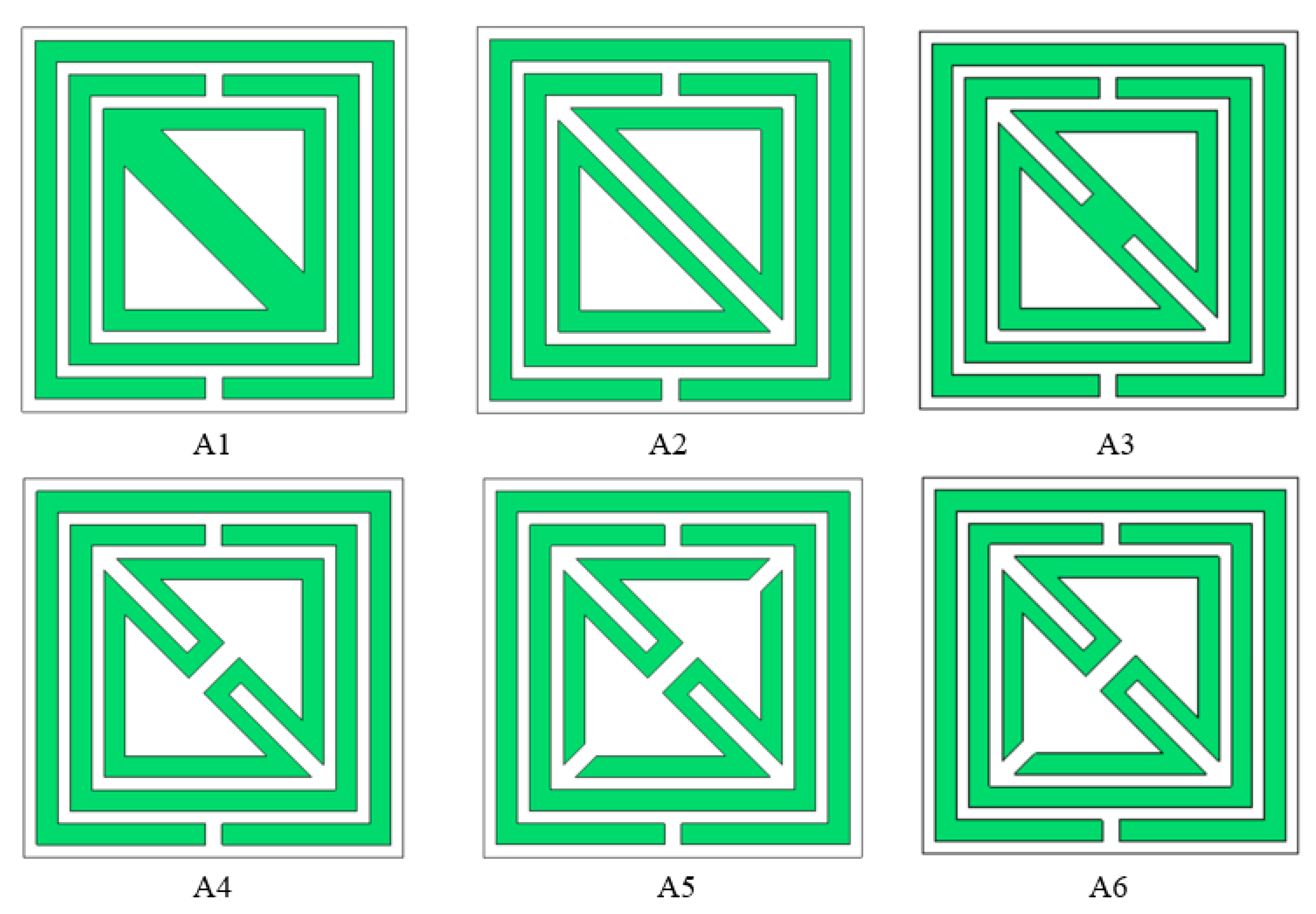
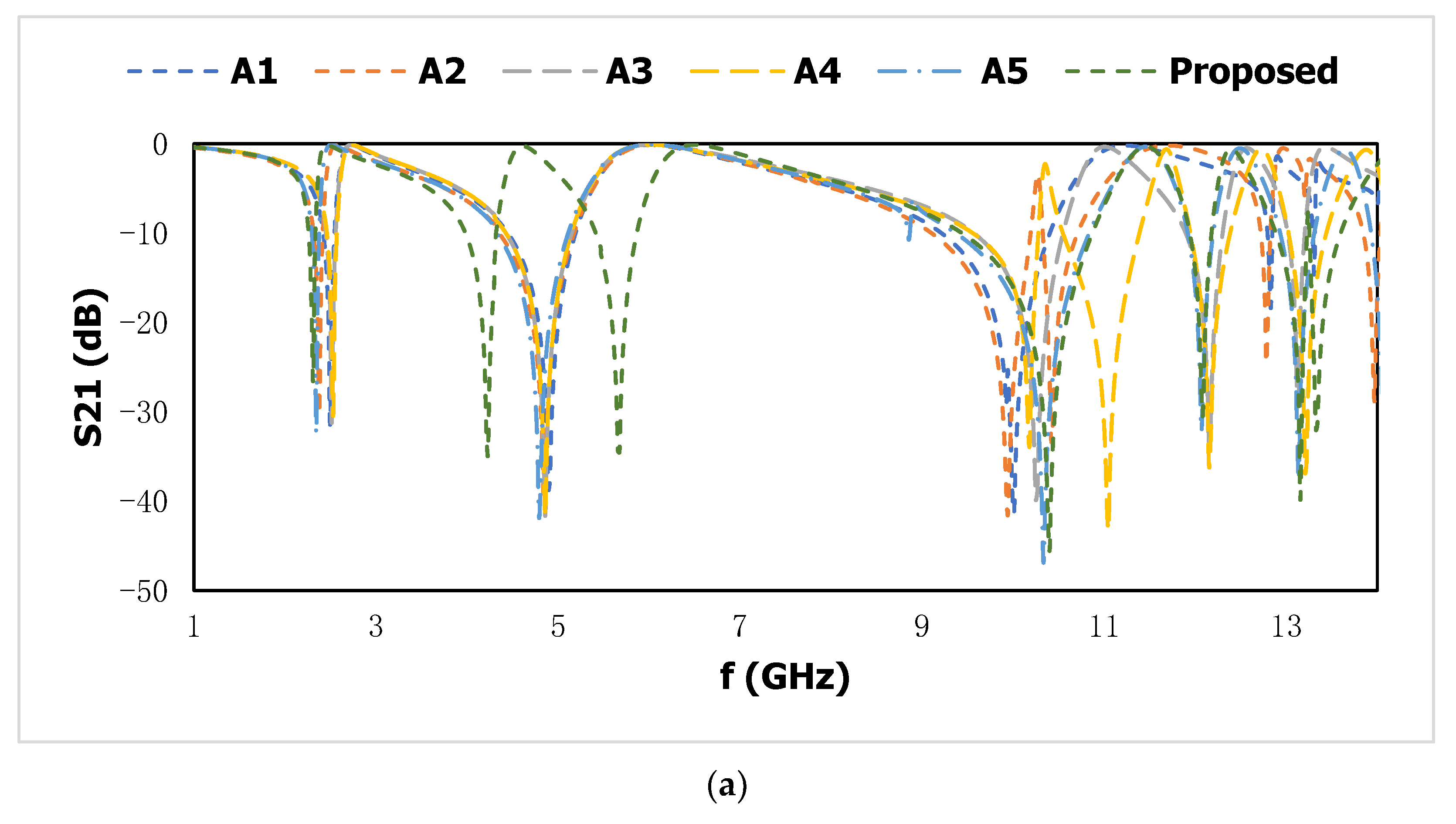
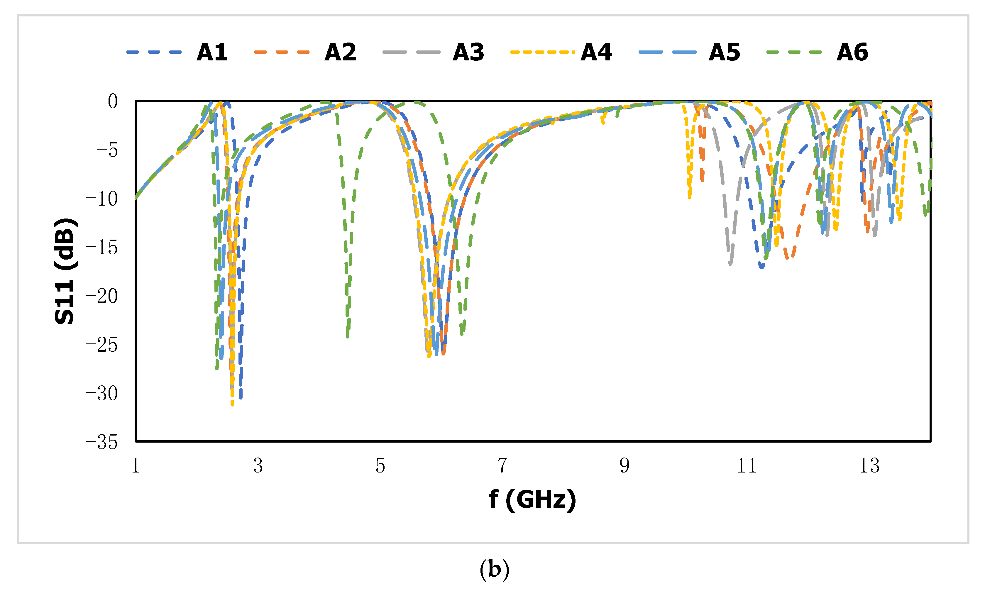
2.3. Design Optimization
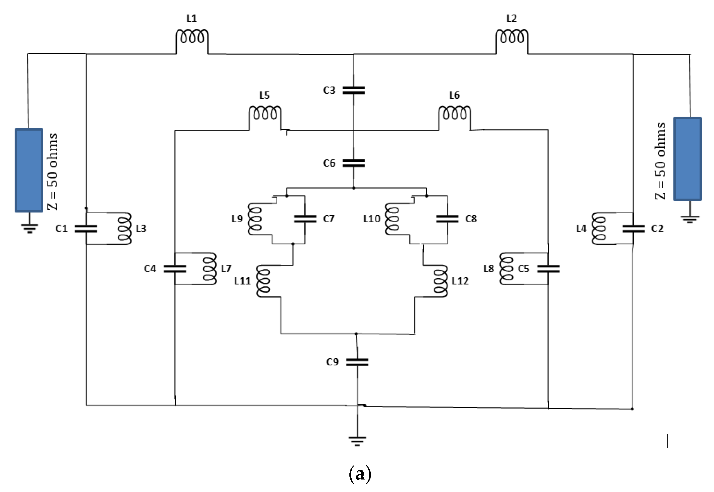
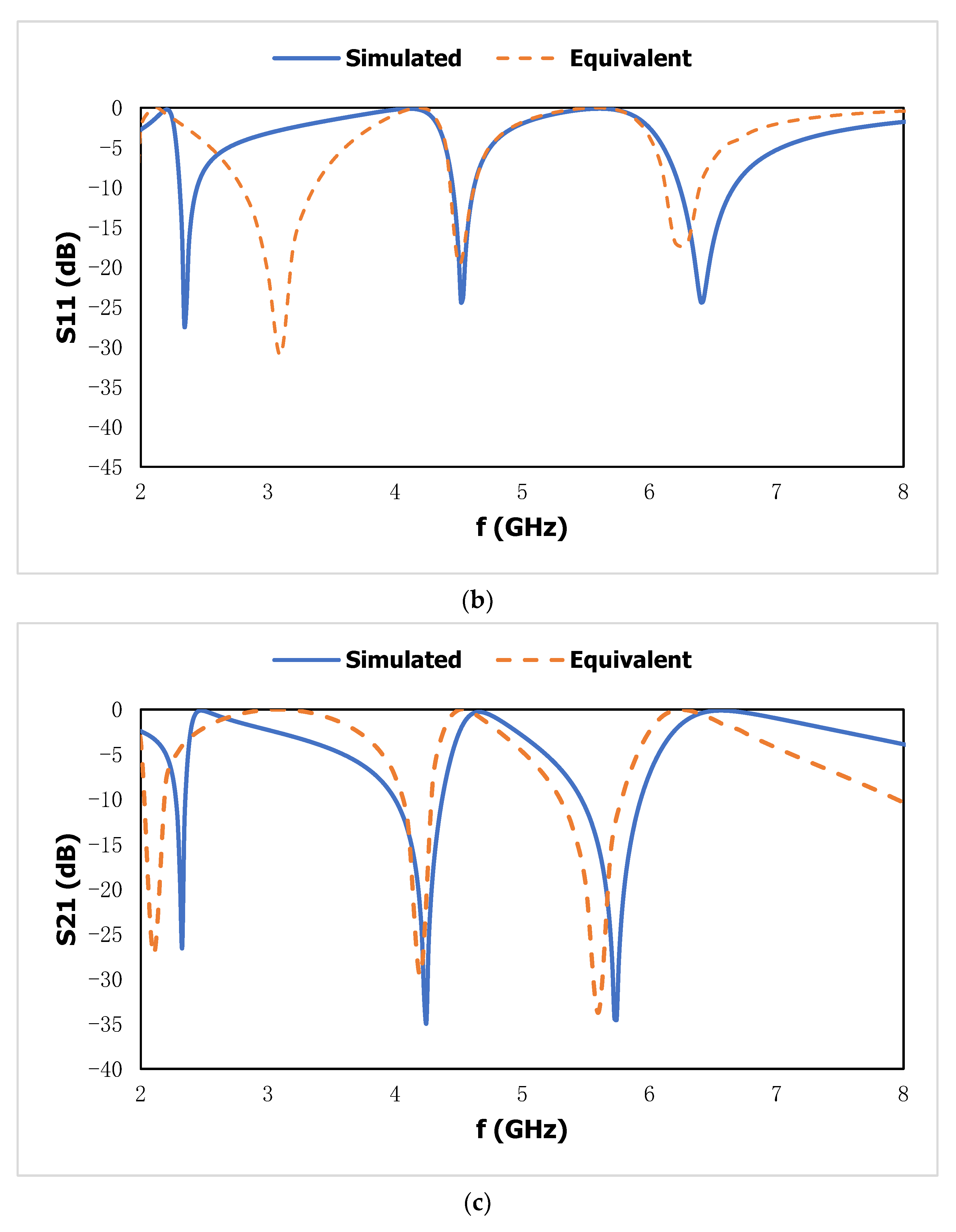
2.4. Equivalent Circuit Model
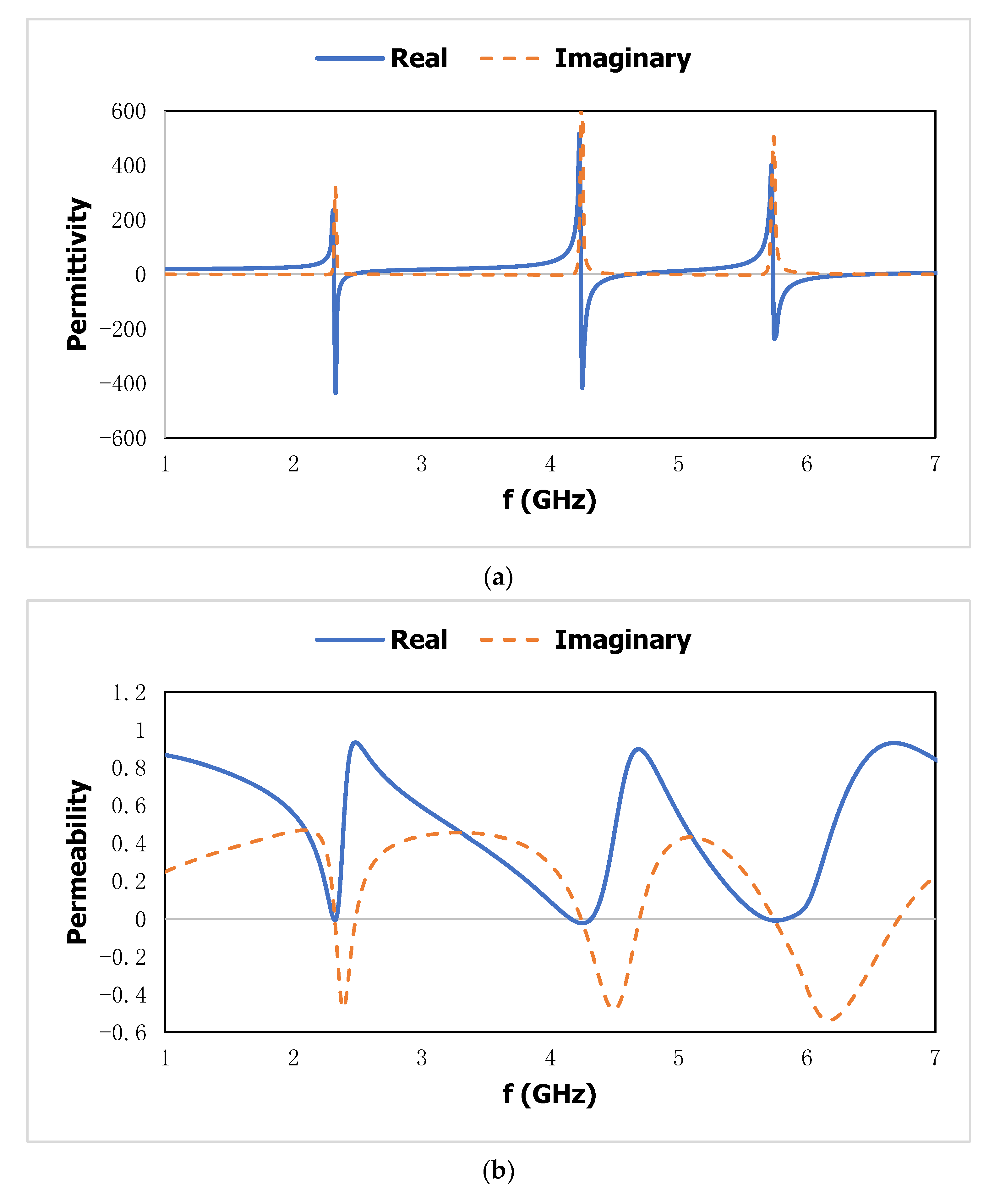
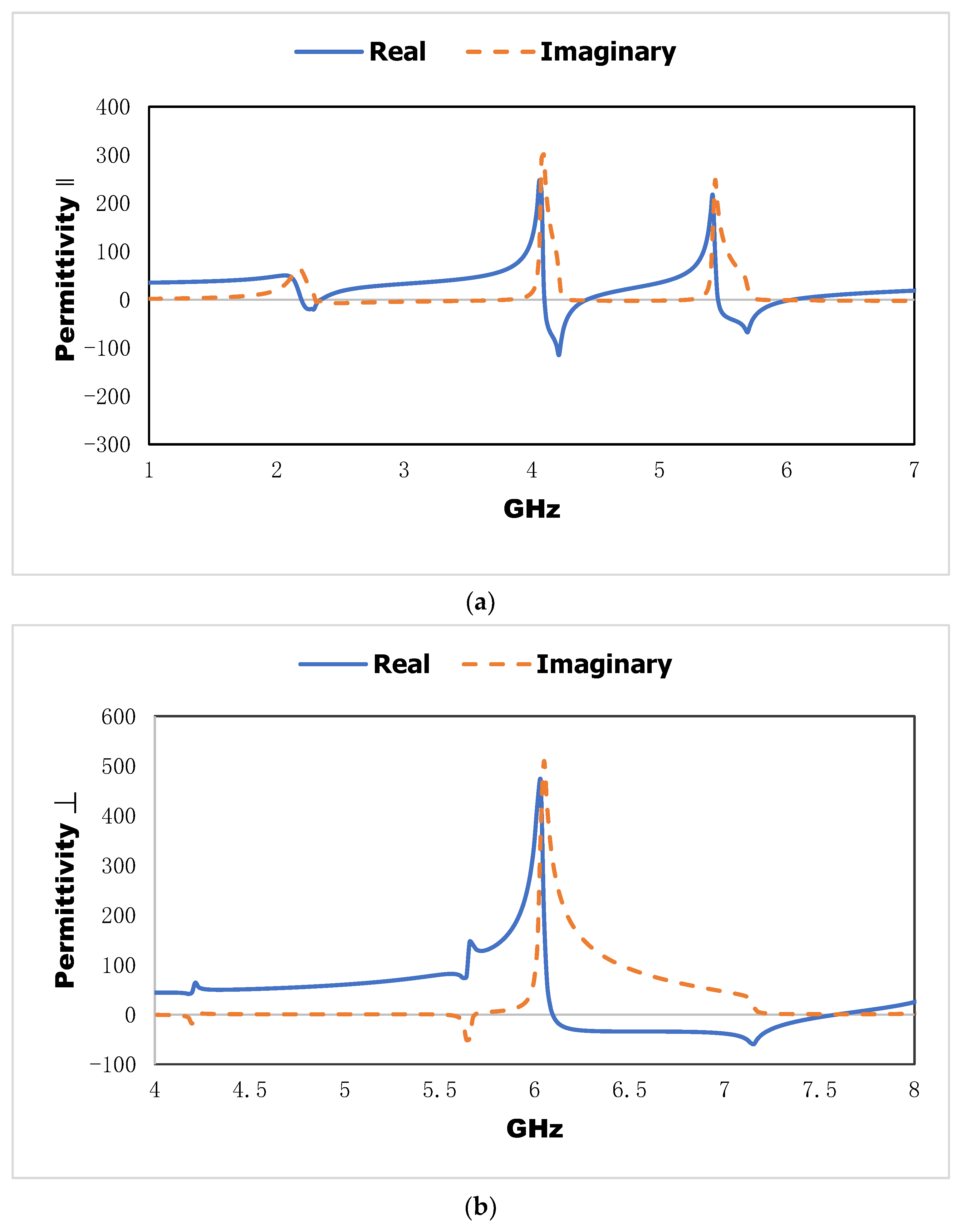
2.5. Effective Parameter
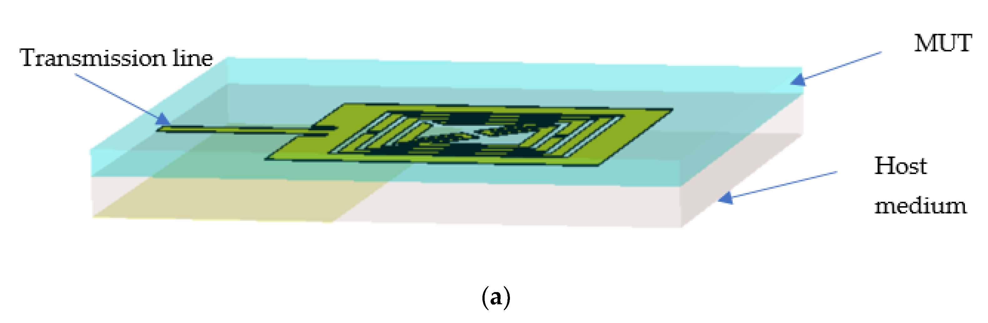
2.6. Sensor Design
3. Results and Discussion
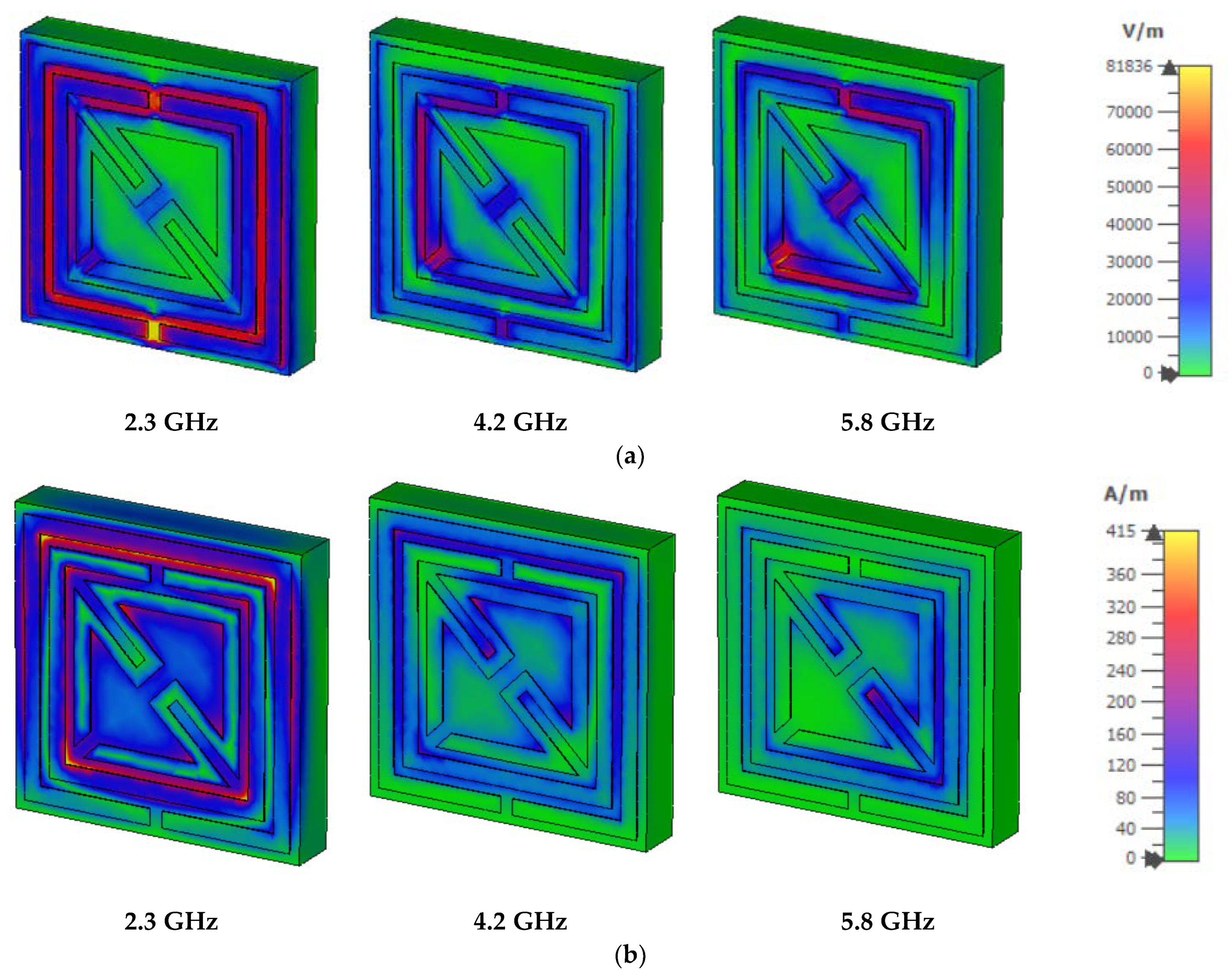
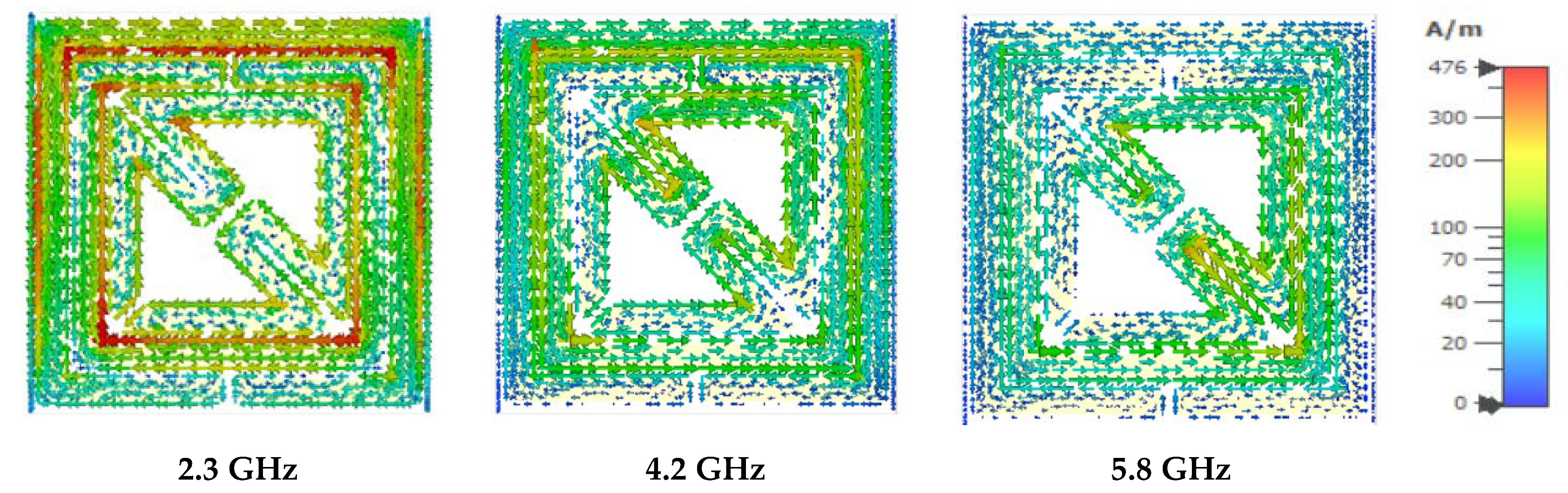
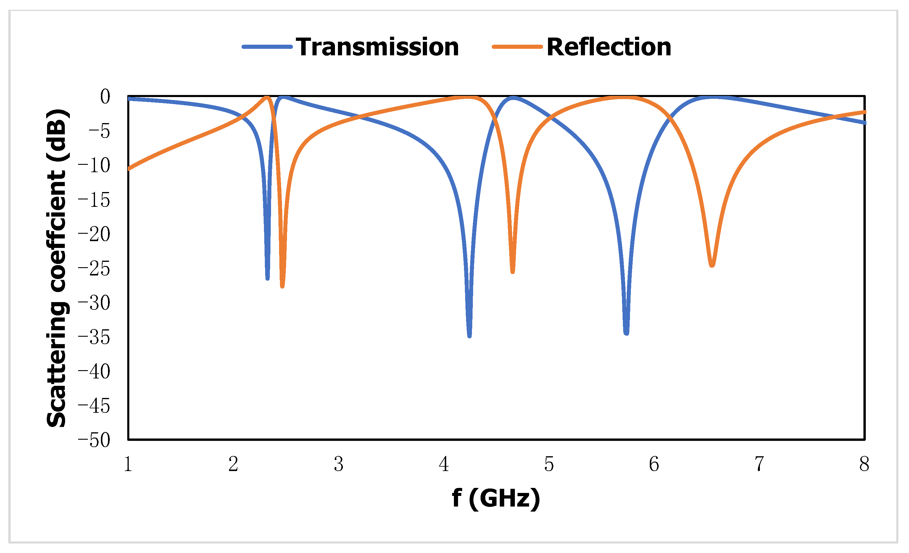
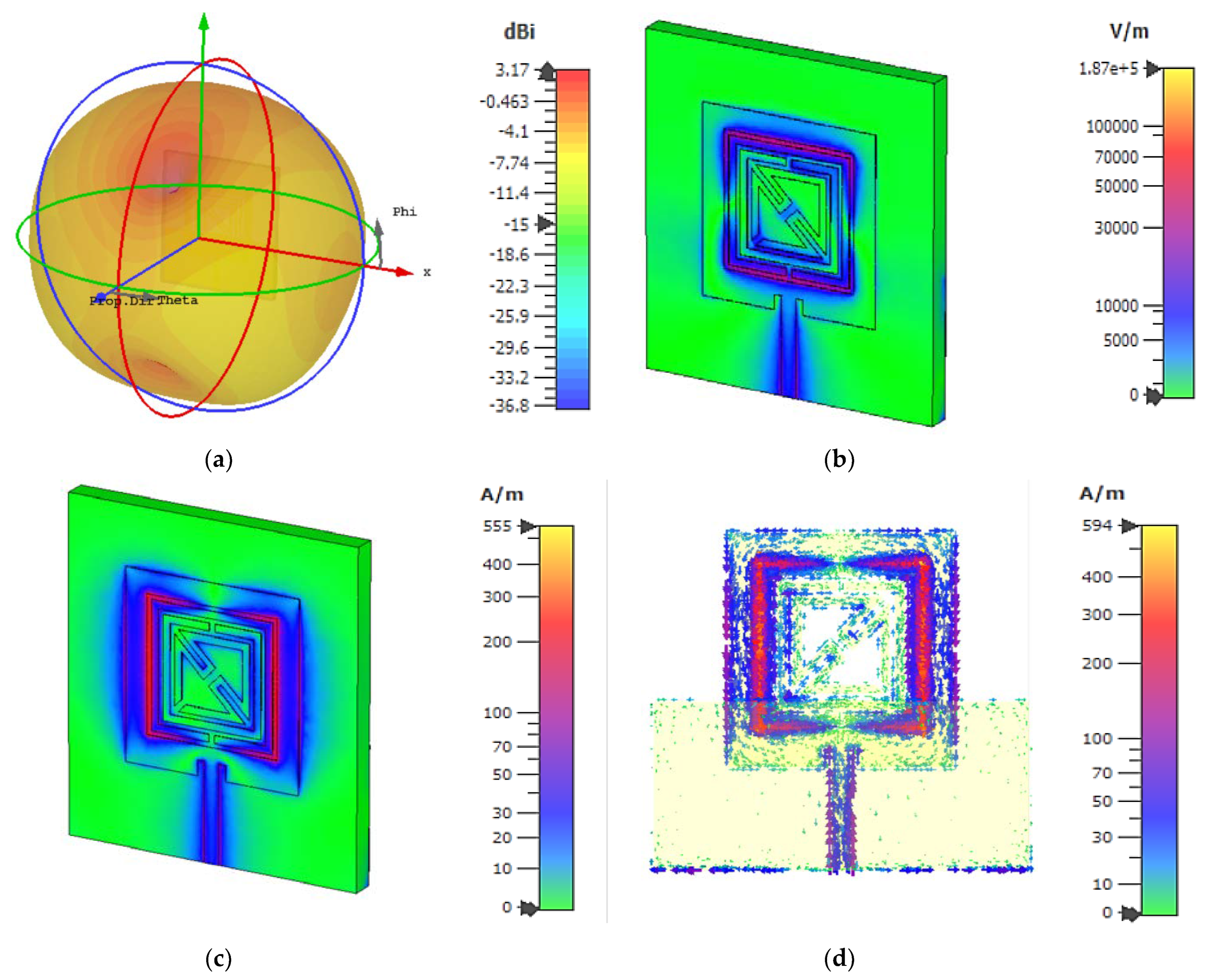
3.1. Metamaterial Unit Cell
3.2. Metamaterial-Incorporated Sensor
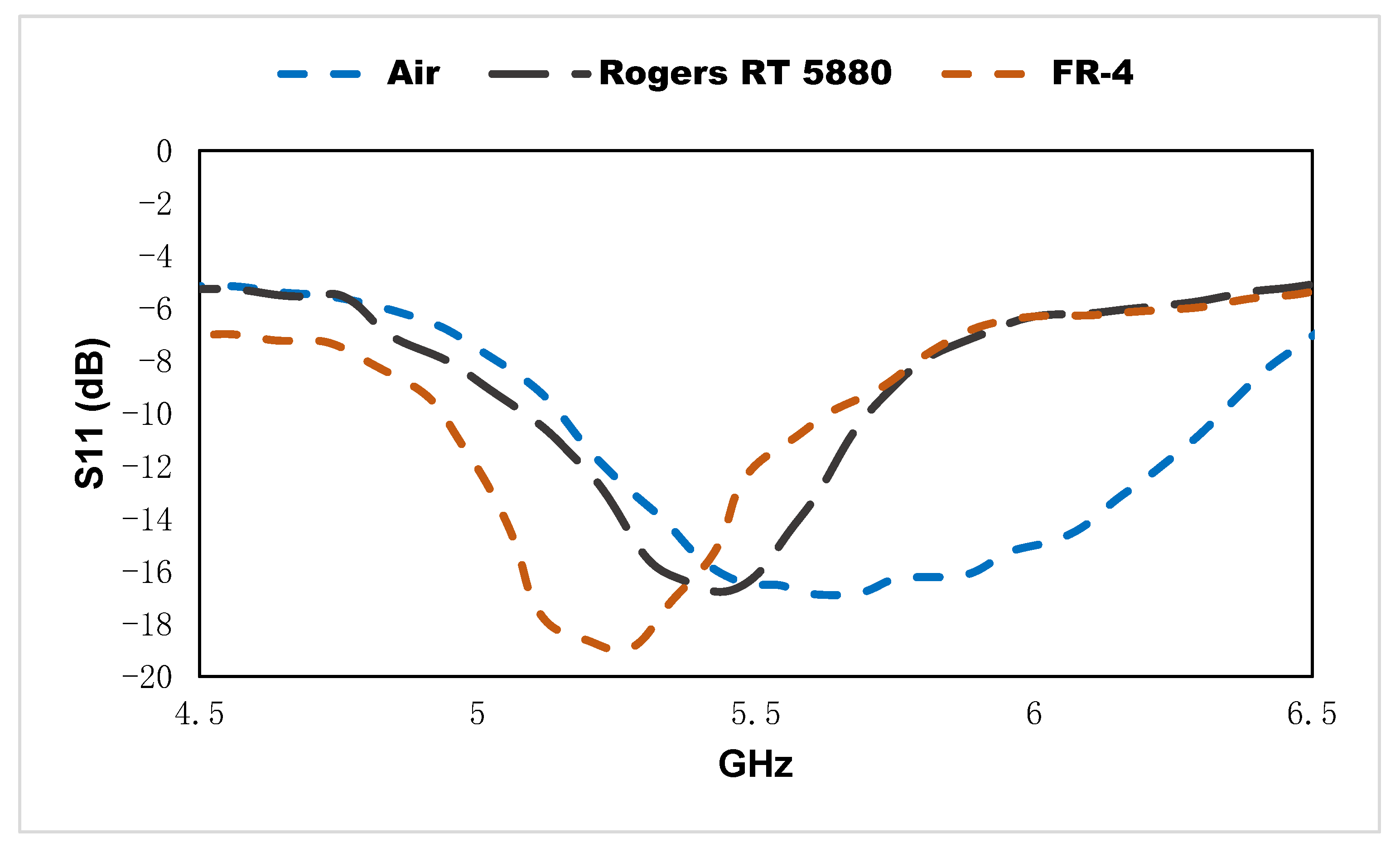
3.3. Performance Evaluation
4. Conclusions
Author Contributions
Funding
Institutional Review Board Statement
Informed Consent Statement
Data Availability Statement
Acknowledgments
Conflicts of Interest
References
- Chen, T.; Li, S.; Sun, H. Metamaterials Application in Sensing. Sensors 2012, 12, 2742–2765. [Google Scholar] [CrossRef] [PubMed]
- Lee, H.-J.; Lee, J.-H.; Moon, H.-S.; Jang, I.-S.; Choi, J.-S.; Yook, J.-G.; Jung, H.-I. A planar split-ring resonator-based microwave biosensor for label-free detection of biomolecules. Sens. Actuators B Chem. 2012, 169, 26–31. [Google Scholar] [CrossRef]
- Shelby, R.A.; Smith, D.R.; Schultz, S. Experimental Verification of a Negative Index of Refraction. Science 2001, 292, 77–79. [Google Scholar] [CrossRef] [PubMed]
- Smith, D.R.; Padilla, W.J.; Vier, D.C.; Nemat-Nasser, S.C.; Schultz, S. Composite Medium with Simultaneously Negative Permeability and Permittivity. Phys. Rev. Lett. 2000, 84, 4184–4187. [Google Scholar] [CrossRef] [PubMed]
- Pendry, J.B.; Holden, A.J.; Robbins, D.J.; Stewart, W.J. Magnetism from conductors and enhanced nonlinear phenomena. IEEE Trans. Microw. Theory Tech. 1999, 47, 2075–2084. [Google Scholar] [CrossRef]
- Ramachandran, T.; Faruque, M.R.I.; Siddiky, A.M.; Islam, M.T. Reduction of 5G cellular network radiation in wireless mobile phone using an asymmetric square shaped passive metamaterial design. Sci. Rep. 2021, 11, 2619. [Google Scholar] [CrossRef]
- Qian, C.; Chen, H. A perspective on the next generation of invisibility cloaks—Intelligent cloaks. Appl. Phys. Lett. 2021, 118, 180501. [Google Scholar] [CrossRef]
- Afsar, S.U.; Faruque, M.R.I.; Hossain, B.; Siddiky, A.M.; Khandaker, M.U.; Alqahtani, A.; Bradley, D.A. A New Octagonal Close Ring Resonator Based Dumbbell-Shaped Tuning Fork Perfect Metamaterial Absorber for C- and Ku-Band Applications. Micromachines 2022, 13, 162. [Google Scholar] [CrossRef] [PubMed]
- Brown, J.A.; Barth, S.; Smyth, B.P.; Iyer, A.K. Compact Mechanically Tunable Microstrip Bandstop Filter with Constant Absolute Bandwidth Using an Embedded Metamaterial-Based EBG. IEEE Trans. Microw. Theory Tech. 2020, 68, 4369–4380. [Google Scholar] [CrossRef]
- Siddiky, A.M.; Faruque, M.R.I.; Islam, M.T.; Abdullah, S.; Khandaker, M.U. Parabolic Split Ring Resonator (PSRR) based MNZ metamaterial with angular rotation for WiFi/WiMax/Wireless/ISM band applications. Chin. J. Phys. 2021, 71, 753–769. [Google Scholar] [CrossRef]
- Li, C.; Jiang, T.; He, Q.; Peng, Z. Stiffness-mass-coding metamaterial with broadband tunability for low-frequency vibration isolation. J. Sound Vib. 2020, 489, 115685. [Google Scholar] [CrossRef]
- Zhang, X.; Davis, J.E.; Güney, D. Ultra-Thin Metamaterial Beam Splitters. Appl. Sci. 2020, 10, 53. [Google Scholar] [CrossRef]
- Siddiky, A.M.; Faruque, M.R.I.; Islam, M.T.; Abdullah, S. A multi-split based square split ring resonator for multiband satellite applications with high effective medium ratio. Results Phys. 2021, 22, 103865. [Google Scholar] [CrossRef]
- Hossain, B.; Faruque, M.R.I.; Islam, S.S.; Islam, M.T. Modified double dumbbell-shaped split-ring resonator-based negative permittivity metamaterial for satellite communications with high effective medium ratio. Sci. Rep. 2021, 11, 19331. [Google Scholar] [CrossRef] [PubMed]
- Hossain, T.M.; Jamlos, M.F.; Dzaharudin, F.; Ismail, M.Y.; Al-Bawri, S.S.; Sugumaran, S.; Salimi, M.N.A. Bandwidth enhancement of five-port reflectometer-based ENG DSRR metamaterial for microwave imaging application. Sensors Actuators A Phys. 2020, 303, 111638. [Google Scholar] [CrossRef]
- Hossain, B.; Faruque, M.R.I.; Islam, M.T.; Singh, M.; Jusoh, M. Triple band microwave metamaterial absorber based on double E-shaped symmetric split ring resonators for EMI shielding and stealth applications. J. Mater. Res. Technol. 2022, 18, 1653–1668. [Google Scholar] [CrossRef]
- Alrayes, N.; Hussein, M.I. Metamaterial-based sensor design using split ring resonator and Hilbert fractal for biomedical application. Sens. Bio-Sens. Res. 2021, 31, 100395. [Google Scholar] [CrossRef]
- Dalgaç, Ş.; Karadağ, F.; Ünal, E.; Özkaner, V.; Bakır, M.; Akgöl, O.; Sevim, U.K.; Delihacıoğlu, K.; Öztürk, M.; Karaaslan, M.; et al. Metamaterial sensor application concrete material reinforced with carbon steel fiber. Mod. Phys. Lett. B 2020, 34, 2050097. [Google Scholar] [CrossRef]
- Haq, T.U.; Ruan, C.; Zhang, X.; Ullah, S. Complementary Metamaterial Sensor for Nondestructive Evaluation of Dielectric Substrates. Sensors 2019, 19, 2100. [Google Scholar] [CrossRef]
- Chen, T.; Zhang, D.; Huang, F.; Li, Z.; Hu, F. Design of a terahertz metamaterial sensor based on split ring resonator nested square ring resonator. Mater. Res. Express 2020, 7, 095802. [Google Scholar] [CrossRef]
- Abdulkarim, Y.I.; Deng, L.; Luo, H.; Huang, S.; Karaaslan, M.; Altıntaş, O.; Bakır, M.; Muhammadsharif, F.F.; Awl, H.N.; Sabah, C.; et al. Design and study of a metamaterial based sensor for the application of liquid chemicals detection. J. Mater. Res. Technol. 2020, 9, 10291–10304. [Google Scholar] [CrossRef]
- Abdulkarim, Y.I.; Deng, L.; Karaaslan, M.; Unal, E. Determination of the liquid chemicals depending on the electrical characteristics by using metamaterial absorber based sensor. Chem. Phys. Lett. 2019, 732, 136655. [Google Scholar] [CrossRef]
- Shahzad, W.; Hu, W.; Ali, Q.; Raza, H.; Abbas, S.M.; Ligthart, L.P. A Low-Cost Metamaterial Sensor Based on DS-CSRR for Material Characterization Applications. Sensors 2022, 22, 2000. [Google Scholar] [CrossRef] [PubMed]
- Butt, M.; Kaźmierczak, A.; Kazanskiy, N.; Khonina, S. Metal-Insulator-Metal Waveguide-Based Racetrack Integrated Circular Cavity for Refractive Index Sensing Application. Electronics 2021, 10, 1419. [Google Scholar] [CrossRef]
- Ma, J.; Tang, J.; Wang, K.; Guo, L.; Gong, Y.; Wang, S. Complex Permittivity Characterization of Liquid Samples Based on a Split Ring Resonator (SRR). Sensors 2021, 21, 3385. [Google Scholar] [CrossRef]
- Saleh, G.; Ateeq, I.; Al-Naib, I. Glucose Level Sensing Using Single Asymmetric Split Ring Resonator. Sensors 2021, 21, 2945. [Google Scholar] [CrossRef] [PubMed]
- Vazquez, F.; Villareal, A.; Rodriguez, A.; Martin, R.; Solis-Najera, S.; Melendez, O.R.M. Electric Field Sensing with a Modified SRR for Wireless Telecommunications Dosimetry. Electronics 2021, 10, 295. [Google Scholar] [CrossRef]
- Gric, T.; Eldlio, M.; Cada, M.; Pistora, J. Analytic solution to field distribution in two-dimensional inhomogeneous waveguides. J. Electromagn. Waves Appl. 2015, 29, 1068–1081. [Google Scholar] [CrossRef]
- Bahl, I.; Prakash, B. Microwave Solid State Circuit Design; Wiley-Interscience: Hoboken, NJ, USA, 2003. [Google Scholar]
- Chen, X.; Grzegorczyk, T.M.; Wu, B.-I.; Pacheco, J.J.; Kong, J.A. Robust method to retrieve the constitutive effective parameters of metamaterials. Phys. Rev. E 2004, 70, 016608. [Google Scholar] [CrossRef] [Green Version]


| Parameter | Width of the Outer Split Ring | Width of the Outer Split Ring | The Gap between the Two Split Rings | The Distance between the Bent Edge | The Width of the Split | The Thickness of the Substrate | The Thickness of the Metallic Layer |
|---|---|---|---|---|---|---|---|
| mm | 0.5 | 0.5 | 0.3 | 1.2 | 0.4 | 1.524 | 0.035 |
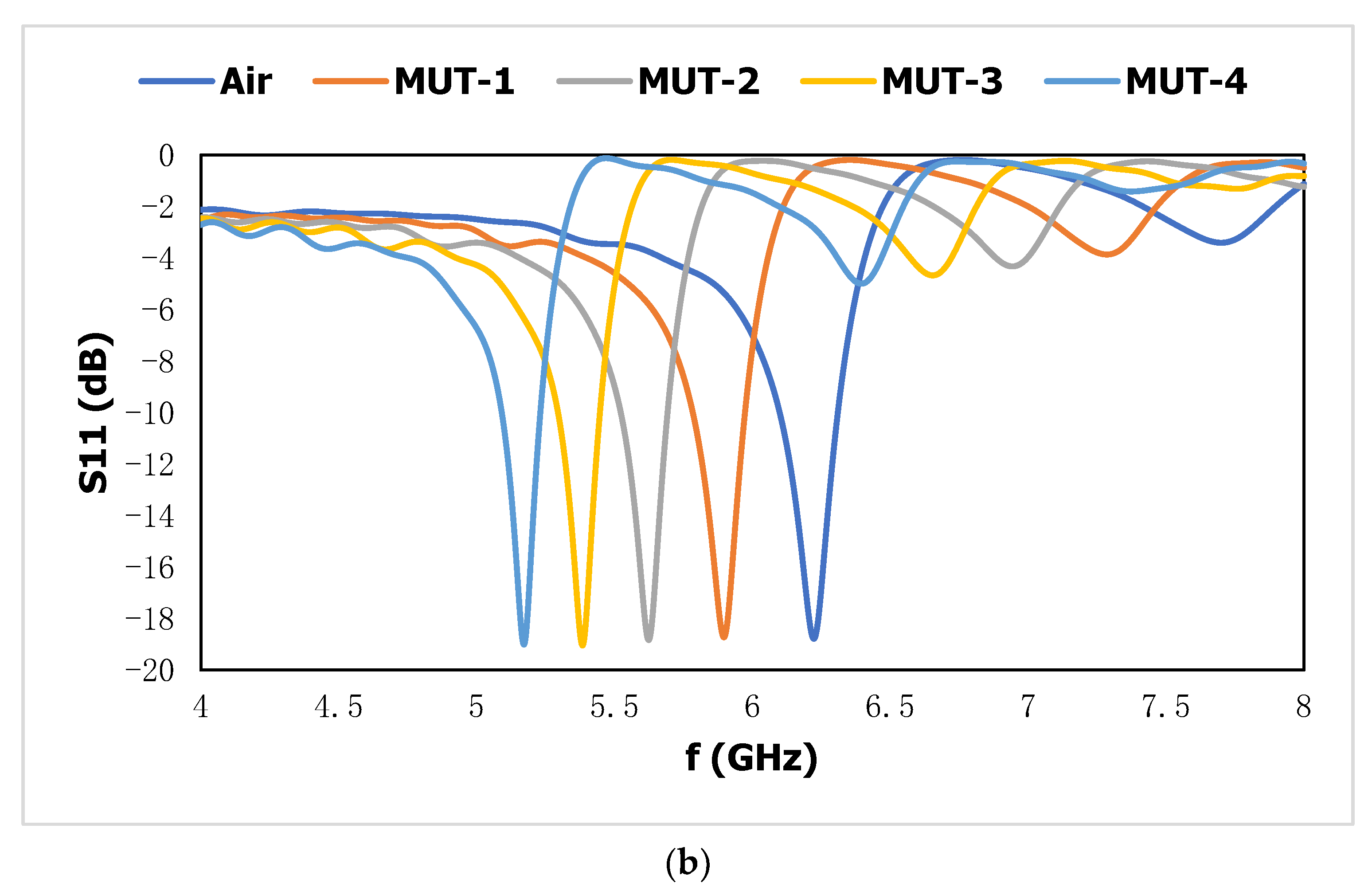
| Dielectric Constant | Bandwidth | Resonance Frequency | FWMH | FOM | ||
|---|---|---|---|---|---|---|
| Air | 1 | 6.1–6.3 | 6.2 | 0.42 | --- | --- |
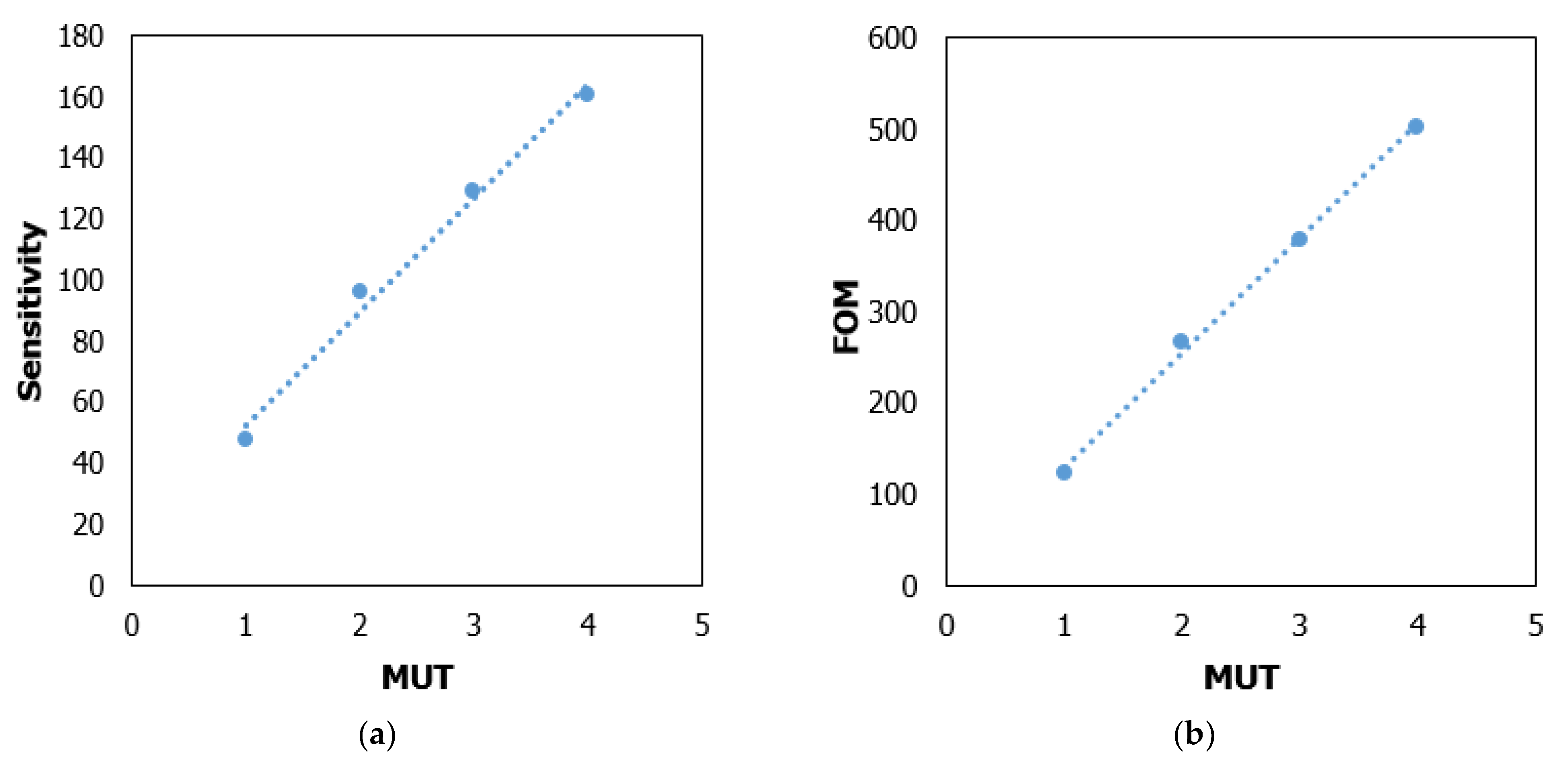
| MUT-1 | 1.5 | 5.8–6.0 | 5.9 | 0.39 | 48 | 123 |
| MUT-2 | 2 | 5.5–5.7 | 5.6 | 0.36 | 96 | 266 |
| MUT-3 | 2.5 | 5.3–5.44 | 5.4 | 0.34 | 129 | 379 |
| MUT-4 | 3 | 5.0–5.26 | 5.2 | 0.32 | 161 | 503 |
| Unit Cell Dimension (mm) | Sensor Dimension (mm) | Substrate | Type | Operating Band (GHz) | Dimension Ratio (λ/D) | Remarks | |
|---|---|---|---|---|---|---|---|
| [18] | 183.5 × 183.5 | 183.5 × 183.5 | ISOLA IS680 | SRR | 1–3 | 0.57 | Concrete sample detection |
| [19] | 3 × 3 | 30 × 25 | FR-4 | CSRR based antenna | 1–4 | 3.7 | detection of the different substrate |
| [21] | 10.16 × 22.86 | 10.16 × 22.86 | FR-4 | Rectangular SRR | 8–12 | 1.31 | Liquid oil detection |
| [22] | 10 × 22 | 10 × 22 | FR-4 | Metamaterial Absorber | 8–12 | 1.38 | Liquid chemical detection |
| [23] | 7 × 7 | 24 × 60 | FR-4 | SRR based antenna | 2–6.5 | 1.56 | Different substrate detection |
| Proposed | 9 × 9 | 20 × 22 | Rogers RT 6002 | SRR based antenna | 4–8 | 4.03 | Detection of the substrate material |
Publisher’s Note: MDPI stays neutral with regard to jurisdictional claims in published maps and institutional affiliations. |
© 2022 by the authors. Licensee MDPI, Basel, Switzerland. This article is an open access article distributed under the terms and conditions of the Creative Commons Attribution (CC BY) license (https://creativecommons.org/licenses/by/4.0/).
Share and Cite
Siddiky, A.M.; Faruque, M.R.I.; Islam, M.T.; Abdullah, S.; Khandaker, M.U.; Tamam, N.; Sulieman, A. Body-Centered Double-Square Split-Ring Enclosed Nested Meander-Line-Shaped Metamaterial-Loaded Microstrip-Based Resonator for Sensing Applications. Materials 2022, 15, 6186. https://doi.org/10.3390/ma15186186
Siddiky AM, Faruque MRI, Islam MT, Abdullah S, Khandaker MU, Tamam N, Sulieman A. Body-Centered Double-Square Split-Ring Enclosed Nested Meander-Line-Shaped Metamaterial-Loaded Microstrip-Based Resonator for Sensing Applications. Materials. 2022; 15(18):6186. https://doi.org/10.3390/ma15186186
Chicago/Turabian StyleSiddiky, Air Mohammad, Mohammad Rashed Iqbal Faruque, Mohammad Tariqul Islam, Sabirin Abdullah, Mayeen Uddin Khandaker, Nissren Tamam, and Abdelmoneim Sulieman. 2022. "Body-Centered Double-Square Split-Ring Enclosed Nested Meander-Line-Shaped Metamaterial-Loaded Microstrip-Based Resonator for Sensing Applications" Materials 15, no. 18: 6186. https://doi.org/10.3390/ma15186186
APA StyleSiddiky, A. M., Faruque, M. R. I., Islam, M. T., Abdullah, S., Khandaker, M. U., Tamam, N., & Sulieman, A. (2022). Body-Centered Double-Square Split-Ring Enclosed Nested Meander-Line-Shaped Metamaterial-Loaded Microstrip-Based Resonator for Sensing Applications. Materials, 15(18), 6186. https://doi.org/10.3390/ma15186186