Abstract
A crashworthiness design of foam-filled local nanocrystallized thin-walled tubes (FLNTs) is proposed by using foam-filled structures and ultrasonic impact surface treatment. The crashworthiness and deformation modes of FLNTs are studied using an experiment and numerical analysis. A finite element numerical model of FLNTs is established, and the processing and test platform of FLNTs is set up to verify the numerical predication and analytical design. The results show that local nanocrystallization is an effective method to enhance crashworthiness for hexagonal FLNTs. The FLNTs with four circumferential continuous stripes of surface nanocrystallization exhibit a level of 47.12% higher specific energy absorption than the untreated tubes in numerical simulations for tubes with a 50% ratio of nanocrystallized area. Inspired by the strength mechanism, a novel nested foam-filled local surface nanocrystallization tube is further designed and studied in detail.
1. Introduction
Thin-walled structures have been widely used in passive vehicle safety systems as among the most typical crash energy absorber elements due to their light weight and high-energy absorbing capacity. Significant efforts have been taken to improve the energy absorbing ability of thin-walled structures under axial crushing. In recent decades, numerous studies were carried out to investigate the energy absorption capacity enhancement by experiments and numerical analyses [,,,,,,,,]. In engineering devices, energy absorbers are designed to absorb the largest impact energy with the smallest mass. In this regard, foam filling has become an effective way for improving energy absorption of thin-walled structures because of the material and structural interaction between wall and foam core. It is therefore very promising to design new energy absorbers by using foam-filled thin-walled tubes.
Recently, much attention has been paid to foam-filled thin-walled structures. A large number of research works have been conducted to study the influence of aluminum foam on energy absorption of thin-walled structures. Meguid et al. [,,,,,] studied the axial collapse behavior of various foam-filled structures and revealed the effect of key influencing parameters on the collapse mechanism and energy characteristics. Goel et al. [] conducted the deformation and energy absorption studies on a multi-wall tube structure with an aluminum core. They concluded that the multi-wall tube structure with foam alters the deformation modes and it results in a substantial increase in energy absorption capacity in comparison with a single or multi-wall tube without a foam core. Hanssen et al. [] conducted experiments on the energy absorption characteristics of circular aluminum columns filled with aluminum foam under both quasi-static and dynamic loading conditions. They reported that the extrusion wall interaction effect caused an increase in the mean load while foam-filled tubes showed less dependency on load conditions. Mirfendereski et al. [] conducted a series of parametric studies on foam-filled tapered tubes and they found that tapered rectangular foam-filled tubes subjected to axial static and dynamic loading conditions were more influenced by foam density. Chen et al. [] carried out analytical and numerical studies on energy absorption characteristics of single-cell and multi-cell foam-filled structures. They found that the interaction effect between foam and column wall caused higher specific energy absorption. An et al. [] proposed a foam-filled thin-wall tube with functionally lateral-graded thickness (FLGT) for accommodating both axial crushing and lateral bending. The numerical and optimal study showed that foam-filled FLGT structures have advantage over the traditional foam-filled uniform thickness (UT) structures under both axial crushing and lateral bending conditions. Yu et al. [] experimentally studied the energy absorption of aluminum foam-filled tubes with different cell structures under compression and they concluded that aluminum foams of higher density contributed to the increase in energy absorption by an interaction effect. Salehi et al. [] experimentally investigated the deformation modes and energy absorption of functionally graded metallic foam-filled tubes under impact loading and the result showed that the Al-A356 foam-filled tube was the best lightweight crashworthy structure. Zhang et al. [] proposed a foam-filled tube of bio-inspired density and the result indicated a further level up to 24% higher energy absorption than the uniform foam-filled tubes. Song et al. [] presented a bio-inspired tube with foam filler based on straw structures and their results showed that a design of four-square holes and four tapered holes has significant energy absorption capacity. Moreover, Song et al. [] proposed a hat sectional (top hats and double hats) thin-walled structure with foam filler. They found that the energy absorption was increased both in the hat section and the foam core when filled with foam. The interaction effect was mainly contributed by the densification effect of aluminum foam. Using experiments and numerical analyses, Zhang et al. [] investigated the crashworthiness for self-lock multi-cell tubes with foam filler. They found that a combination of aluminum foam filler and square tube envelope was the most effective design compared to the expanded polystyrene foam filler. Hou et al. [,] carried out multi-objective optimization of square and tapered circular foam-filled structures and they further improved the crashworthiness of the structures. Sun and his co-workers [,,,,,,] studied crashworthiness for a series of foam-filled thin-walled structures and carried out multi-objective optimization for the structures. In addition, the crashworthiness for thin-walled structures filled with different foam fillers, for examples, polyurethane foam [,,,], polyvinyl chloride foam [], auxetic foam [,], liquid nanofoam [,], etc., was further studied.
In the existing literature, thin-walled energy absorbers are mainly fabricated by steels due to their excellent mechanical properties and low costs. Therefore, it is difficult to improve their energy absorption capacities if there is no change in geometry and material. Fortunately, with the development of nanotechnology, surface nanocrystallization techniques have been proposed to improve the mechanical and chemical properties of materials. The principle of surface nanocrystallization involves making the surface of bulk metals or subsurfaces with severe plastic deformation by applying a load such that the grains are gradually refined to form nanograins []. Lu and Lu [] first proposed a process of surface nanocrystallization by surface mechanical attrition treatment (SMAT) and shot peening treatment. Material grains can also be refined by angular extrusion [], high-pressure torsion [,], ultrasonic impact treatment [,], ultrasonic shot peening treatment [,], etc. Lu et al. [] found that SMAT can significantly increase the yield strength of 304 stainless steel, and the fully SMATed energy absorbing device was manufactured and designed to capitalize its excellent mechanical properties. This design can absorb more impact energy if it is compared with the existing Toyota Yaris energy absorbing device. Xu et al. [] studied a local surface nanocrystallized energy-absorbing structure and they showed that it has 64.29% higher energy absorption than an ordinary tube. Meanwhile, they found that the model with three circumferential staggered stripes is an optimal design, and the ratio of local nanocrystallization was 50%.
Currently the main energy absorbers are thin-walled structures with square sections. Researchers [,,,,] investigated axial crushing behaviors for cylindrical shells through theoretical analyses. Some available studies demonstrated that for axial crashing, hexagonal tubes are more appropriate for energy absorption than the others with polygonal shapes []. As a result, regular hexagon tubes are adopted to achieve the research objective in this study. Xu et al. [] demonstrated that local surface nanocrystallization can significantly enhance energy absorption of thin-walled structures without the expense of an increased peak crushing force. However, the crashworthiness of foam-filled local surface nanocrystallized thin-walled structures with hexagonal section and the interaction effect between local nanocrystallized wall and foam have not been studied. In this study, aluminum foam filling and local surface nanocrystallization are combined to design a type of lightweight energy absorption device with better crashworthiness.
For the above reasons, a foam-filled local surface nanocrystallized hexagonal thin-walled tube is proposed for axial crashing energy absorption. The technique of ultrasonic impact treatment (UIT) is employed to generate surface nanocrystallization with a 50% proportion of treated area in the structure. The material properties for thin-walled structures and aluminum foam are obtained by testing. Subsequently, the energy absorption capacity of foam-filled local nanocrystallization tube is carried out using an experiment and the interaction effect is analyzed. A finite element (FE) model is established to analyze the foam-filled local nanocrystallized tubes under axial crushing with different stripe numbers, with a 50% ratio of nanocrystallization area. The interaction effect of foam-filled local UIT tube is significantly enhanced compared with the untreated tubes. In addition, a novel nested UIT tube with foam-filled is designed and studied based on the strength mechanism.
2. Experimental Tests
2.1. Ultrasonic Impact Treatment
The UIT equipment is assembled on a three-dimensional platform for producing nanocrystallization patterns in an efficient manner. Ring columns with different masses are attached to the UIT head to enhance the effect of UIT and to avoid the waggle of impact head during processing. The impact head is made of W18Cr4V high speed steel, which can bear repeated impact at high frequencies. The UIT equipment is driven by an ultrasonic generator with a frequency range of 18–22 kHz, maximum displacement amplitude of 50 μm and maximum power output of 1 kW. The UIT equipment further contains a piezo-ceramic ultrasonic transducer and an ultrasonic horn made from strength material. The samples of 304 stainless steel are placed in a 0.6 mm groove of the specimen fixture.
2.2. Material Properties
According to Yang et al. [], the elastic limit for nanocrystallized AISI 304 specimens could be enhanced to a level of 42% compared with the untreated specimens. Therefore, stainless steel 304 is chosen for fabricating foam-filled energy absorbing structures. The main chemical composition of this material is shown in Table 1. The nanocrystallized specimens are nanocrystallized on double sides with a processing time 90 s/cm2. The tensile specimens are obtained by cutting the nanocrystallized specimens. The material properties of nanocrystallized specimens are measured by tensile test. Universal testing machine AGS-X 300 kN and Epsilon 3442 axial extensometer are utilized for tensile and compression testing. The strain is measured by Epsilon 3442 axial extensometer to ensure test accuracy. The tensile speed is 4 mm/min and the strain–stress relation of tensile specimens is shown in Figure 1. The tensile test result indicates that Young’s modulus of steel is increased from 176.9 GPa to 199.5 GPa after nanocrystallization processing, as depicted in Table 2. Meanwhile, the elastic limit of nanocrystallized specimen reaches 709.6 MP, which has increased by 150%.

Table 1.
Chemical compositions of SUS304.
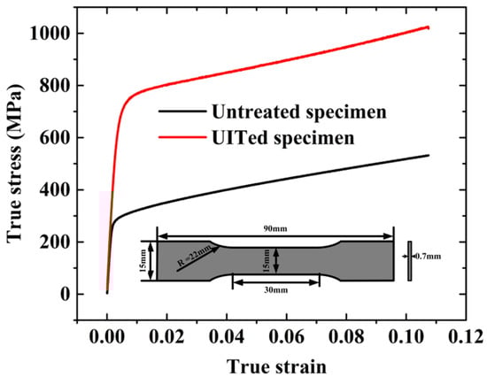
Figure 1.
True stress–true strain relation of SUS 304.
Table 2.
Tensile properties of untreated and nanocrystallized 304 stainless steel.
Aluminum closed-foam is selected as the filled foam block. The deformation modes of hexagonal foam under quasi-static compression test are shown in Figure 2. To measure its material constants, hexagonal aluminum foam columns with a side length of 26 mm, height of 80 mm and relative density of 0.28 g/cm3 are fabricated for the uniaxial compression tests, as shown in Figure 3. The loading speed is 4 mm/min and the stress–strain relation of the foam specimen is presented in Figure 3. Clearly, it has three stages: stage (I), elastic deformation; stage (II), long stable deformation with almost constant stress, defined as the plateau stress σp; and stage (III), densification region. From Figure 3, Young’s modulus is 60.4 MPa and the foam plateau stress σp is 2.8 MPa [].
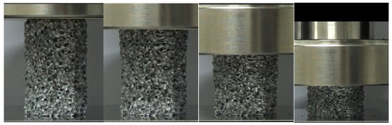
Figure 2.
Deformation modes of hexagonal foam under quasi-static compression test.
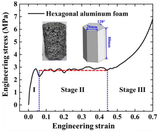
Figure 3.
Stress–strain relation of hexagonal aluminum column.
2.3. Specimen Preparation
The local nanocrystallized tubes are fabricated by welding two plates. Firstly, two stainless steel plates of SUS 304 are locally nanocrystallized by UIT. Next, each plate is bent to 120° along the bending lines. Then, two bent plates are welded into one thin-walled tube by argon-arc welding. The location for welding lines is in the middle of one side. Lastly, the foam column is filled into the local nanocrystallized tube to form a foam-filled tube, as shown in Figure 4. The geometrical parameters for the regular hexagonal tube are: side length of 26.7 mm, height of 80 mm and thickness of 0.7 mm.
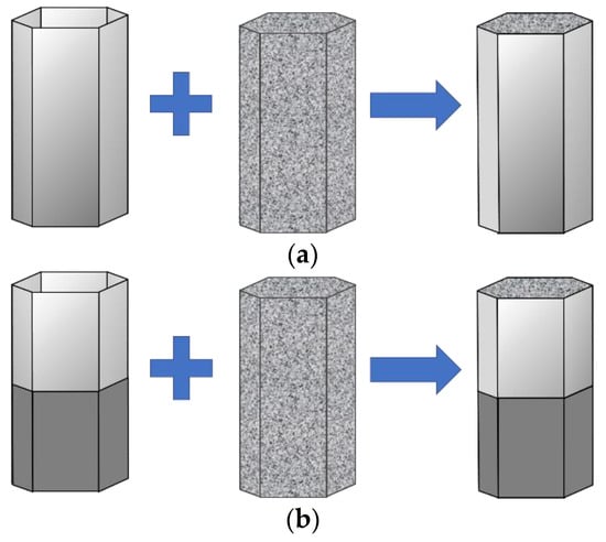
Figure 4.
The fabrication process of foam-filled tubes: (a) untreated tube; (b) local nanocrystallized tube.
The welding is the last process of the overall manufacturing process. The nanocrystallized steel plate is welded into tubes using the argon-arc welding machine. The welding material shows similar ultimate strength with the 304 steel which was also indicated in the published references [,]. In this study, both the nanocrystallized tube and the untreated tube is manufactured by welding. Additionally, the welding lines of both tubes are fabricated using the same welding process. In this situation, the effect of thermal on the comparison of crashworthiness between the untreated tube and nanocrystallized tube is ignorable.
2.4. Quasi-Static Axial Compression Tests
The quasi-static compression tests are conducted for untreated empty and foam-filled tubes, local nanocrystallized empty and foam-filled tube and the validity of the test result is verified a finite element analysis. The velocity of load is 4 mm/min during compression, and the whole buckling process is recorded using a digital camera. The compression displacement is set as 70% for the specimen height and all crashworthiness criteria are calculated within the range.
2.4.1. Empty Thin-Walled Tube
As presented in Figure 5, the LNT-2 (Local Nanocrystallized Tube with 2 stripes) load is greater than the UT (untreated tube) load in the whole range. The result in Table 3 indicates that an increase in EA (energy absorption) and SEA (specific energy absorption) of two-stripe tube reaches 46.02% and 46.03% compared to the untreated tube. Meanwhile, PCF (peak crushing force) of the two-stripe tube increases by 13%. The increase for MCF (mean crushing force) reveals that local nanocrystallized tubes have more superior crashworthiness than untreated tubes. Subsequently, the energy absorption capacity for specimens with different stripe numbers is presented in Section 4 and Section 5. Table 3 shows that local nanocrystallization can improve the crashworthiness for thin-walled structures. With regard to deformation energy, the strain energy of nanocrystallized region is increased due to the increase in stress, as shown in Equation (1). The elastic strain energy absorbed by the structure is expressed as:
where W is the elastic strain energy, σx is the normal stress, εx is the linear strain and V is the volume of structures.
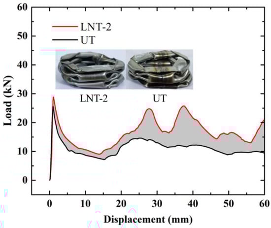
Figure 5.
Load–displacement relation of UT and LNT-2.
Table 3.
Energy absorption parameters of empty tubes.
2.4.2. Foam-Filled Thin-Walled Tube
The compression tests of the FUT (foam-filled untreated tube) and FLNT-2 (foam-filled local nanocrystallized tube) are carried out and Figure 6 shows deformation modes for FUT and FLNT-2 at different compression stages. The load–displacement relation for UT and LNT is shown in Figure 7a,b, respectively. In order to exhibit the interaction effect between the tube and foam, the “LNT-2 + Foam” line is drawn, which denotes the linear summation of crushing force for LNT-2 and foam. The shaded area indicates an increase in energy absorption due to the interaction effect and it increases from 232 J to 445 J, as shown in Table 4. The result shows that local nanocrystallization can dramatically enhance the interaction effect between the wall and foam. Table 4 shows that the specific energy absorption and peak crushing force of FLNT-2 are increased by 40.67% and 28.40% compared to FUT, respectively. However, the increase in peak force has a negative effect on structural crashworthiness. Therefore, it is necessary to optimize the energy capacity of the structures.
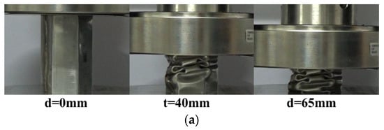
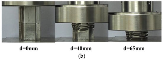
Figure 6.
Deformation modes of foam-filled tubes under axial compression test: (a) FUT; and (b) FLNT-2.
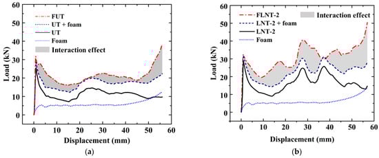
Figure 7.
The interaction effect of foam-filled tubes: (a) UT and (b) LNT-2.
Table 4.
Effects of foam on energy absorption for thin-walled tubes.
3. Numerical Simulation
A comprehensive study by FE numerical simulations is conducted using Abaqus/Explicit to analyze, design and optimize local nanocrystallized hexagonal thin-walled tubes. The FE model details are shown in Figure 8. The top of the hexagonal tube is impacted by a moving rigid block with an impact velocity of 3 m/s while the bottom is fixed. The fixed plate and movable wall are defined as rigid components to enhance computational efficiency. The linear elastic theory for an aluminum foam in the elastic stage is adopted and the model of “crushable foam” is used to characterize the material properties in the plastic stage. Finite elements of type are 8-node linear brick (C3D8R) selected in the FE simulation.
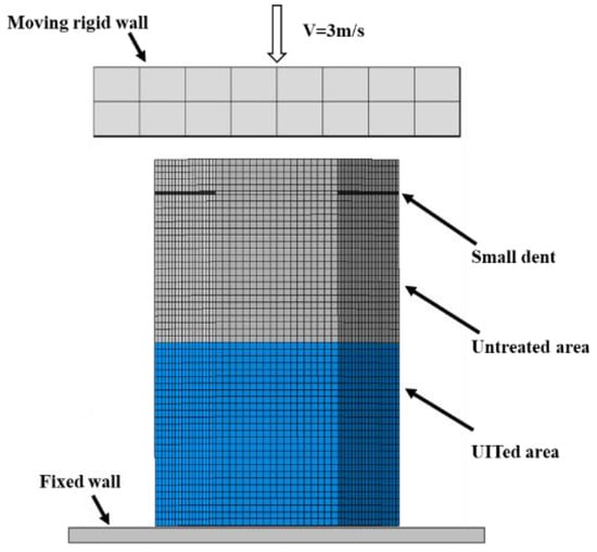
Figure 8.
The finite element model.
Based on the experimental data in Section 2.2, the material properties of the structures are summarized in Table 5 and Table 6, respectively. The classical isotropic plasticity theory of metal is used to define material properties for the UIT-treated area and the untreated area of thin-walled tubes. Small dents are introduced to induce stable deformation modes [,,]. The thin-walled tube is modeled using 4-node shell elements with reduced integration and hourglass control. The surface–surface contact algorithm is adopted to simulate the interaction between the foam and wall based on the real situation. In addition, the general contact between tube and rigid wall is set while the friction coefficient of contact is 0.3. The “penalty contact” is selected in tangential behavior. In the normal behavior, the “Hard Contact” is chosen in this study.
Table 5.
Material properties of the thin-walled tube.
Table 6.
Material properties for aluminum foam.
3.1. Crashworthiness Assessment
The energy absorption of thin-walled structures is mainly dependent on its deformation during crush. To evaluate the crashworthiness of the structure, several widely used assessment parameters are selected, including energy absorption (EA), specific energy absorption (SEA), peak crushing force (PCF) and mean crushing force (MCF) [].
EA can be calculated by integrating the displacement force under the load–displacement curve. It is given by
where x0 is the crushing displacement and F(x) is the crushing force.
SEA represents the energy absorption per unit mass and it can accurately measure the energy absorption capacity of the structure. It is given by
where m is the total mass of the structure. MCF is another effective criterion, which is defined as the average load during the crushing process. MCF is expressed as
3.2. Validation of FE Models
FE models for FUT and FLNT-2 are validated by comparing the deformation modes, load–displacement curve and crashworthiness assessments with an experiment. It is observed from Figure 9 and Figure 10 that numerical prediction for the number of folds, position of the first fold and load–displacement curve is in very agreement with the experiment. Very good agreement between FE solution and the experiment is also observed in Table 7 and the maximum error is less than 10%. From the comparison study, it is concluded that the proposed FE model is accurate and reliable for predicting energy absorption for local nanocrystallized thin-walled hexagonal tubes.
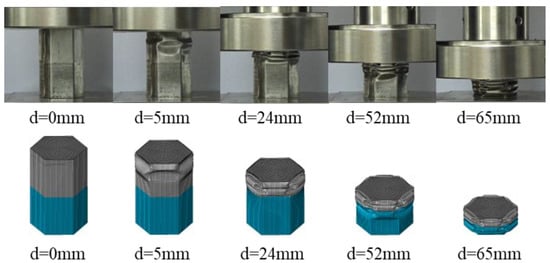
Figure 9.
Comparison of two-stripe tube deformation modes by experiment and FE simulation.
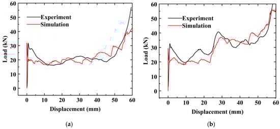
Figure 10.
Comparison of load–displacement relation for foam-filled thin-walled tubes: (a) FUT and (b) FLNT-2.
Table 7.
Error analysis of energy absorption between FE solutions and experiment.
A mesh sensitivity study for aluminum foam is presented in Figure 11a. The mesh size of foam varies from 4 mm to 10 mm. The result shows that the variation in EA is stable [] for a mesh size smaller than 2 mm. Hence, the mesh size of the foam model is defined as 2.0 mm. Furthermore, a mesh convergence study of shell element is conducted and presented in Figure 11b. It can be seen that EA tends to converge when the mesh size is less than 1.5 mm. Therefore, a mesh size of 1.5 mm is used to model the thin-walled structures in the subsequent numerical cases.
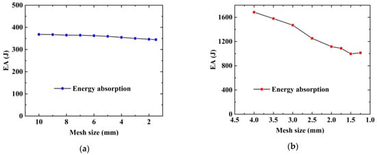
Figure 11.
Mesh convergence study: (a) aluminum foam and (b) local nanocrystallized tube.
4. Result and Discussion
4.1. Effects of Local Nanocrystallization Layout on Crashworthiness
The result from the experiment and FE simulation shows that FLNT-2 has a higher SEA compared to FUT. In a previous work [,], the authors concluded that local nanocrystallized thin-walled tubes with axial stripes could significantly improve the peak crushing force for buckling-resistant structures and tubes with circumferential horizonal stripes could enhance energy absorption without the expense of an increased peak crushing force. Hence, circumferential continuous horizontal stripes are adopted in this study and the proportion of nanocrystallization is 50%. In addition, empty LNT models with different stripe numbers are simulated to analyze the interaction effect between local nanocrystallization and foam in LNT.
In Figure 12, the final FE deformation modes with different stripe numbers are presented, where light gray denotes the untreated region and blue denotes the nanocrystallized region. In order to confine PCF, the stripe near the top of the hexagonal tube is set as the untreated region. The load–displacement relation of hexagonal tubes with even stripe numbers is presented in Figure 13a, including LNT-2, LNT-4, LNT-6, LNT-8 and LNT-10. The result indicates that all curves of local nanocrystallized specimens are above the curve of the untreated specimen. Figure 13b shows the EA of all LNT structures has a significant enhancement compared with UT. As shown in Figure 14, EA of the hexagonal tube increases first and then decreases with increasing stripe numbers. The crashworthiness assessment is summarized in Table 8. EA of LNT-4 is higher than the other LNT structures with a significant increase in PCF. Additionally, EA of LNT-2 and LNT-6 is essentially equal with values of 997 J and 998 J, respectively. However, PCF of LNT-2 is 29.66 kN, which is lower than that of LNT-6 (37.43 kN). Therefore, LNT-2 is a superior model with reference to all the crashworthiness assessments.
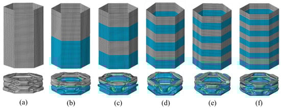
Figure 12.
Ultimate deformation modes for models with even circumferential stripes: (a) UT; (b) LNT-2; (c) LNT-4; (d) LNT-6; (e) LNT-8; (f) LNT-10.
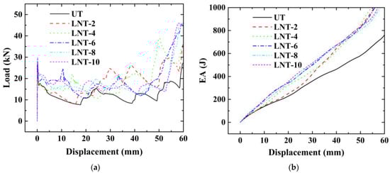
Figure 13.
The effect of stripe number for tubes with even circumferential stripes: (a) load–displacement relations; (b) energy–displacement relations.
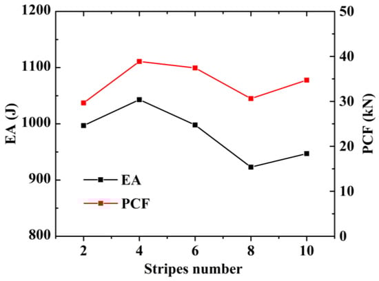
Figure 14.
Effect of stripes on energy absorption and PCF.
Table 8.
Effect of stripes on energy absorption properties.
4.2. Local Nanocrystallization Layouts on Interaction Effects
The load–displacement relation of FLNTs with different stripes and the corresponding deformation modes are presented in Figure 15a and Figure 16, respectively. It is clear that all FLNTs have better energy absorption performance than FUT, as shown in Figure 15b. The result of FE simulation for FLNTs is summarized in Table 9. It is noted that EA reaches the maximum of 1789 J for FLNT-4, with an increase of 47.12% compared with FUT. Moreover, PCF is only increased by 16.15% compared to the untreated tube. The result reveals that FLNT-4 is a design with superior crashworthiness. As shown in Figure 16, the effect of aluminum foam on the performance is obviously related to the deformation modes and it can be attributed to the interaction effect between the wall and foam. As shown in Figure 17, more foam core in FLNT-4 is extruded into folds compared with FUT, and it dramatically enhances the densification effect. Meanwhile, energy dissipation is contributed by interfacial friction between the foam and tube wall. The correlation between the stripe number and energy absorption of EA and PCF is presented in Figure 18. The model crashworthiness is discounted with increasing stripe numbers. The great discrepancy between energy absorption shows that the crashworthiness of thin-walled structures is significantly affected by local nanocrystallization layouts.
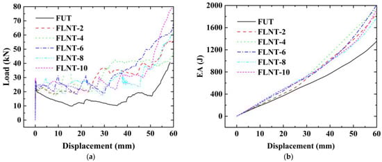
Figure 15.
Effect of stripe number for filled tubes: (a) load–displacement relations and (b) energy–displacement relations.
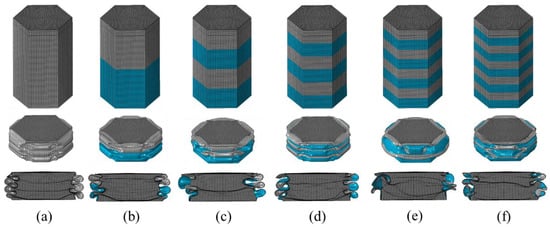
Figure 16.
Deformation modes: (a) untreated; (b) FLNT-2; (c) FLNT-4; (d) FLNT-6; (e) FLNT-8; and (f) FLNT-10.
Table 9.
Crashworthiness data for different stripe number filled tubes.
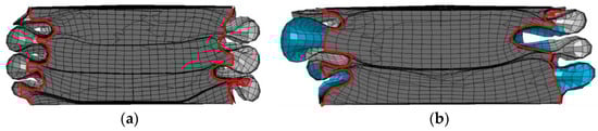
Figure 17.
Comparison of densification effect: (a) FUT and (b) FLNT-4.
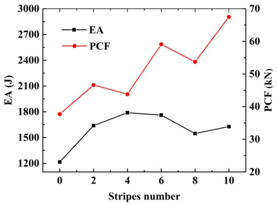
Figure 18.
Effect of stripe number on energy absorption and peak crushing force.
To verify the design parameters of FE numerical simulation, a test specimen for FLNT-4 is fabricated in Figure 19. The deformation modes and load–displacement relation under quasi-static axial loading and crashworthiness criteria are presented in Figure 20 and Table 10, respectively. The experiment result for FLNT-4 shows better energy dissipation performance and the error is less than 5% (compared with FE numerical solution). Therefore, it is concluded that the proposed local surface nanocrystallization design significantly enhances the energy absorption capacity of foam-filled hexagonal thin-walled tubes.
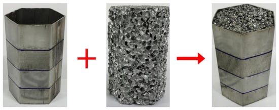
Figure 19.
Configuration of FLNT-4.
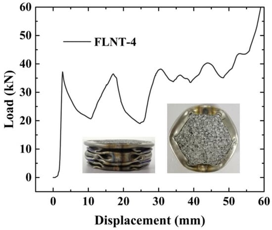
Figure 20.
Load–displacement relation for FLNT under compression test.
Table 10.
Energy absorption properties for FLNT-4.
4.3. Foam-Filled Nested Tubular Structure Design
As seen in Table 9, the interaction effect of FLNT-4 is much stronger than that of FUT with an increase of 53.93% of EA. This section aims to explore the strengthening mechanism of energy absorption performance from the aspect of EA and deformation modes.
Table 11 presents the partition energy absorption and contribution of interaction effect for FUT and FLNT-4. The tabular result is obtained by numerical simulation. EA for an individual tube and aluminum foam is also tabulated in Table 11. The interaction effect can be represented by the increase in EA. From the result of tube EA, it is clear that local surface nanocrystallization can sufficiently improve the performance of energy absorption of an individual tube (from 682 J to 1043 J). Meanwhile, it is noted that the tube EA of the nanocrystallization foam-filled tube (FLNT-4, 1264 J) is much larger than that of the nanocrystallization individual tube (1043 J). This observation indicates that local surface nanocrystallization also enhances the interaction effect of foam-filled tubes. Similar observation can be found in the foam EA of foam-filled tubes. It increases from 401 J to 525 J after nanocrystallization (from FUT to FLNT-4). In conclusion, local surface nanocrystallization greatly improves the energy absorption performance of the individual tube as well as the interaction effect between the tube and foam.
Table 11.
Partition energy absorption and contribution of interaction effect via FE analysis.
The collapse mode for FLNT-4 under axial compression is shown in Figure 21. Clearly, the crushed foam filler can be divided into two regions: (i) densified region and (ii) extremely densified region []. The inner part for the foam filler could be approximated into a hexagonal prism, which is extruded as the densified region under axial loading. The surrounding part of foam filler can be approximatively subjected to the multi-axial loading with folding, which results in more and closer interaction between foam cells and nanocrystallization wall. In addition, the interaction effect is generated by additional energy dissipation mechanism, including the resistance of inward bulking and the interfacial friction between the filler and the tube wall [,].
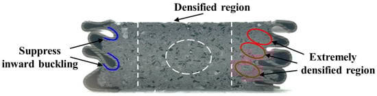
Figure 21.
Cut-away image of crushed FLNT-4 section.
Inspired by the above investigation, two nested foam-filled local surface nanocrystallization tubes with four stripes are designed as shown in Figure 22, i.e., (1) N-1-FLNT-4 (Figure 22a), two hexagonal local nanocrystallization tubes with different heights and a ring-like foam core, and (2) N-2-FLNT-4 (Figure 22b), a hexagonal foam filled inside the N-1-FLNT-4. To reduce the initial PCF, the height of the inner tube or the inner hexagonal foam is set to 75 mm, which is 5 mm lower than the outer tube. The crushing force–displacement relations for FLNT-4, N-1-FLNT-4 and N-2-FLNT-4 are illustrated in Figure 23. Clearly, the energy absorption of N-1-FLNT-4 and N-2-FLNT-4 is significantly higher than FLNT-4, which indicates that the nested tube exhibits better energy absorption performance than the single-walled tube. Furthermore, it is observed that the curve of N-2-FLNT-4 has the most peaks, followed by N-1-FLNT-4 and FLNT-4. This phenomenon demonstrates that more plastic folds and foam extrusion behavior are generated in N-2-FLNT-4. To further study the energy absorption performance of the two nested tubes, Figure 24 depicts the deformation modes. Clearly, the aluminum foam in N-2-FLNT-4 is extruded to generate more densified regions than that in N-1-FLNT-4, due to an increase in the contact area between tube wall and foam. Therefore, N-2-FLNT-4 is a superior design. Subsequently, Table 12 presents a comparison of the crashworthiness parameters between N-2-FLNT-4 and FLNT-4. As expected, the EA and SEA of N-2-FLNT-4 are obviously higher than that of FLNT-4, with a 65.51% and 23.99% increase, respectively. It can be concluded that nested foam-filled local surface nanocrystallization structures are shown to be more superior to the single structures in terms of crashworthiness.
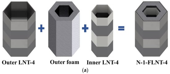
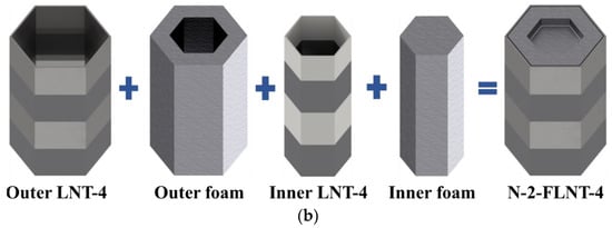
Figure 22.
A novel nested foam-filled local surface nanocrystallization tube: (a) N-1-FLNT-4; (b) N-2-FLNT-4.
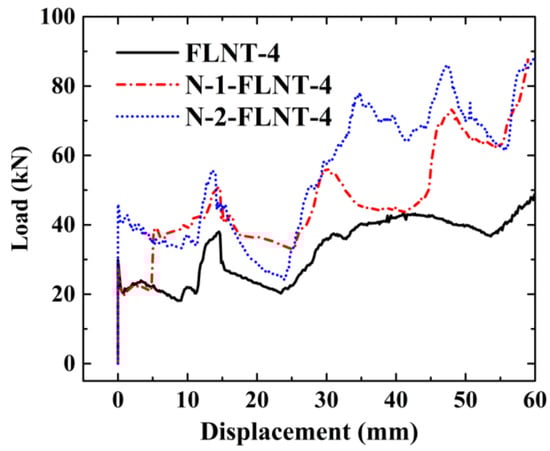
Figure 23.
Load–displacement relation of FLNT and N-FLNT-4.
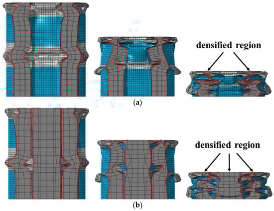
Figure 24.
The deformation modes: (a) N-1-FLNT-4; (b) N-2-FLNT-4.
Table 12.
Energy absorption properties for N-FLNT-4 and FUT.
5. Conclusions
A new type of aluminum foam-filled hexagonal thin-walled structure treated with local nanocrystallization is proposed. The crashworthiness of FLNTs under axial crushing is investigated through an experiment and finite element simulation. The effects of different local nanocrystallization layouts on the energy absorption capacity for FLNTs is studied using numerical simulations. The numerical result concludes that: (i) Proper local surface nanocrystallization can significantly enhance the crashworthiness of hexagonal thin-walled tubes. Compared with UT and FUT, the SEA of LNT-2 is significantly increased by 46.19% and 26.61%, respectively. (ii) FLNT-4 is a better design for aluminum foam-filled local nanocrystallized hexagonal thin-walled tubes with respect to crashworthiness. By comparing the interaction effect for foam-filled tubes, FLNT-4 can dramatically improve the interaction effect from 176 J to 388 J. In addition to numerical analysis, a test specimen for FLNT-4 is fabricated and an experiment is conducted to verify the conclusions. Very good agreement between the experiment and FE numerical solutions has been reported. Moreover, a novel nested foam-filled local surface nanocrystallization tube is designed based on the interaction effect. The simulation result concludes that SEA for N-2-FLNT-4 is further enhanced with an 23.99% increase compared to FLNT-4. The proposed design idea is very promising for the further development of thin-walled energy absorption devices using other metallic and non-metallic materials.
Author Contributions
Conceptualization, X.X. and W.W.; methodology, W.W. and Z.Z.; software, W.W. and Y.W.; validation, W.W., Y.W. and Z.Z.; formal analysis, Z.T. and Z.Z.; investigation, X.X. and Y.W.; resources, X.X.; data curation, Z.Z. and Z.T.; writing—original draft preparation, W.W.; writing—review and editing, W.W., X.X. and C.W.L.; visualization, W.W.; supervision, C.W.L.; project administration, X.X.; funding acquisition, X.X., C.W.L. and Z.T. All authors have read and agreed to the published version of the manuscript.
Funding
This work was supported by the National Natural Science Foundation of China (Grant No. 12002071), the project of Key Laboratory of Impact and Safety Engineering (Ningbo University), Ministry of Education (Grant No. CJ202204), City University of Hong Kong (Grant No. 7005653) and the Fundamental Research Funds for the Central Universities (Grant No. DUT21LK35).
Informed Consent Statement
No applicable.
Data Availability Statement
This study did not report any data.
Conflicts of Interest
There are no competing financial interests to report.
References
- Al Galib, D.; Limam, A. Experimental and numerical investigation of static and dynamic axial crushing of circular aluminum tubes. Thin-Walled Struct. 2004, 42, 1103–1137. [Google Scholar] [CrossRef]
- Isaac, C.W.; Oluwole, O. Structural response and performance of hexagonal thin-walled grooved tubes under dynamic impact loading conditions. Eng. Struct. 2018, 167, 459–470. [Google Scholar] [CrossRef]
- Kannan, I.V.; Rajkumar, R. Deformation and energy absorption analysis of simple and multi-cell thin-walled tubes under quasi-static axial crushing. Int. J. Crashworthiness 2020, 25, 121–130. [Google Scholar] [CrossRef]
- Liu, Y. Crashworthiness design of multi-corner thin-walled columns. Thin-Walled Struct. 2008, 46, 1329–1337. [Google Scholar] [CrossRef]
- Rajak, D.K.; Kumaraswamidhas, L.A.; Das, S. Investigation of Mild Steel Thin-Wall Tubes in Unfilled and Foam-Filled Triangle, Square, and Hexagonal Cross Sections Under Compression Load. J. Mater. Eng. Perform. 2018, 27, 1936–1944. [Google Scholar] [CrossRef]
- Xu, X.; Zhang, Y.; Wang, J.; Jiang, F.; Wang, C.H. Crashworthiness design of novel hierarchical hexagonal columns. Compos. Struct. 2018, 194, 36–48. [Google Scholar] [CrossRef]
- Zhang, X.; Cheng, G.; Zhang, H. Theoretical prediction and numerical simulation of multi-cell square thin-walled structures. Thin-Walled Struct. 2006, 44, 1185–1191. [Google Scholar] [CrossRef]
- Zhang, X.; Zhang, H. Energy absorption of multi-cell stub columns under axial compression. Thin-Walled Struct. 2013, 68, 156–163. [Google Scholar] [CrossRef]
- Zhang, Y.; Xu, X.; Wang, J.; Chen, T.; Wang, C.H. Crushing analysis for novel bio-inspired hierarchical circular structures subjected to axial load. Int. J. Mech. Sci. 2018, 140, 407–431. [Google Scholar] [CrossRef]
- Attia, M.S.; Meguid, S.A.; Nouraei, H. Nonlinear finite element analysis of the crush behaviour of functionally graded foam-filled columns. Finite Elem. Anal. Des. 2012, 61, 50–59. [Google Scholar] [CrossRef]
- Meguid, S.A.; Attia, M.S.; Monfort, A. On the crush behaviour of ultralight foam-filled structures. Mater. Des. 2004, 25, 183–189. [Google Scholar] [CrossRef]
- Meguid, S.A.; Heyerman, J.; Stranart, J.C. Finite element modeling of the axial collapse of foam-filled structures. J. Spacecr. Rocket. 2002, 39, 828–832. [Google Scholar] [CrossRef]
- Meguid, S.A.; Stranart, J.C.; Heyerman, J. On the layered micromechanical three-dimensional finite element modelling of foam-filled columns. Finite Elem. Anal. Des. 2004, 40, 1035–1057. [Google Scholar] [CrossRef]
- Meguid, S.A.; Yang, F.; Hou, P. Crush behaviour of foam-filled thin-walled conical frusta: Analytical, numerical and experimental studies. Acta Mech. 2016, 227, 3391–3406. [Google Scholar] [CrossRef]
- Yang, F.; Wang, M.; Hassan, M.T.Z.; Meguid, S.A.; Hamouda, A.M.S. Effect of interfacial friction and fold penetration on the progressive collapse of foam-filled frustum using kinematically admissible model. Int. J. Crashworthiness 2018, 23, 581–592. [Google Scholar] [CrossRef]
- Goel, M.D. Deformation, energy absorption and crushing behavior of single-, double- and multi-wall foam filled square and circular tubes. Thin-Walled Struct. 2015, 90, 1–11. [Google Scholar] [CrossRef]
- Hanssen, A.C.; Langseth, M.; Hopperstad, O.S. Static and dynamic crushing of circular aluminium extrusions with aluminium foam filler. Int. J. Impact Eng. 2000, 24, 475–507. [Google Scholar] [CrossRef]
- Mirfendereski, L.; Salimi, M.; Ziaei-Rad, S. Parametric study and numerical analysis of empty and foam-filled thin-walled tubes under static and dynamic loadings. Int. J. Mech. Sci. 2008, 50, 1042–1057. [Google Scholar] [CrossRef]
- Chen, W.G.; Wierzbicki, T. Relative merits of single-cell, multi-cell and foam-filled thin-walled structures in energy absorption. Thin-Walled Struct. 2001, 39, 287–306. [Google Scholar] [CrossRef]
- An, X.Z.; Gao, Y.K.; Fang, J.G.; Sun, G.Y.; Li, Q. Crashworthiness design for foam-filled thin-walled structures with functionally lateral graded thickness sheets. Thin-Walled Struct. 2015, 91, 63–71. [Google Scholar] [CrossRef]
- Yu, Y.; Cao, Z.; Tu, G.; Mu, Y. Energy Absorption of Different Cell Structures for Closed-Cell Foam-Filled Tubes Subject to Uniaxial Compression. Metals 2020, 10, 1579. [Google Scholar] [CrossRef]
- Salehi, M.; Mirbagheri, S.M.H.; Ramiani, A.J. Efficient energy absorption of functionally-graded metallic foam-filled tubes under impact loading. Trans. Nonferrous Met. Soc. China 2021, 31, 92–110. [Google Scholar] [CrossRef]
- Zhang, Y.; He, S.; Liu, J.; Zhao, W.; Gong, X.; Yu, J. Density gradient tailoring of aluminum foam-filled tube. Compos. Struct. 2019, 220, 451–459. [Google Scholar] [CrossRef]
- Song, J.; Xu, S.; Xu, L.; Zhou, J.; Zou, M. Experimental study on the crashworthiness of bio-inspired aluminum foam-filled tubes under axial compression loading. Thin-Walled Struct. 2020, 155, 106937. [Google Scholar] [CrossRef]
- Song, H.W.; Fan, Z.H.; Yu, G.; Wang, Q.C.; Tobota, A. Partition energy absorption of axially crushed aluminum foam-filled hat sections. Int. J. Solids Struct. 2005, 42, 2575–2600. [Google Scholar] [CrossRef]
- Zhang, H.; Zhang, X. Axial crushing of self-lock multi-cell tubes with foam filler and tube envelope. Thin-Walled Struct. 2020, 155, 106847. [Google Scholar] [CrossRef]
- Hou, S.; Han, X.; Sun, G.; Long, S.; Li, W.; Yang, X.; Li, Q. Multiobjective optimization for tapered circular tubes. Thin-Walled Struct. 2011, 49, 855–863. [Google Scholar] [CrossRef]
- Hou, S.; Li, Q.; Long, S.; Yang, X.; Li, W. Crashworthiness design for foam filled thin-wall structures. Mater. Des. 2009, 30, 2024–2032. [Google Scholar] [CrossRef]
- Song, X.; Sun, G.; Li, G.; Gao, W.; Li, Q. Crashworthiness optimization of foam-filled tapered thin-walled structure using multiple surrogate models. Struct. Multidiscip. Optim. 2013, 47, 221–231. [Google Scholar] [CrossRef]
- Sun, G.; Li, G.; Hou, S.; Zhou, S.; Li, W.; Li, Q. Crashworthiness design for functionally graded foam-filled thin-walled structures. Mater. Sci. Eng. A-Struct. Mater. Prop. Microstruct. Process. 2010, 527, 1911–1919. [Google Scholar] [CrossRef]
- Sun, G.; Li, S.; Liu, Q.; Li, G.; Li, Q. Experimental study on crashworthiness of empty/aluminum foam/honeycomb-filled CFRP tubes. Compos. Struct. 2016, 152, 969–993. [Google Scholar] [CrossRef]
- Sun, G.; Liu, T.; Huang, X.; Zhen, G.; Li, Q. Topological configuration analysis and design for foam filled multi-cell tubes. Eng. Struct. 2018, 155, 235–250. [Google Scholar] [CrossRef]
- Zhang, Y.; Sun, G.; Li, G.; Luo, Z.; Li, Q. Optimization of foam-filled bitubal structures for crashworthiness criteria. Mater. Des. 2012, 38, 99–109. [Google Scholar] [CrossRef]
- Zheng, G.; Wu, S.; Sun, G.; Li, G.; Li, Q. Crushing analysis of foam-filled single and bitubal polygonal thin-walled tubes. Int. J. Mech. Sci. 2014, 87, 226–240. [Google Scholar] [CrossRef]
- Ghamarian, A.; Azarakhsh, S. Axial crushing analysis of polyurethane foam-filled combined thin-walled structures: Experimental and numerical analysis. Int. J. Crashworthiness 2019, 24, 632–644. [Google Scholar] [CrossRef]
- Li, Z.; Chen, W.; Hao, H. Dynamic crushing and energy absorption of foam filled multi-layer folded structures: Experimental and numerical study. Int. J. Impact Eng. 2019, 133, 103341. [Google Scholar] [CrossRef]
- Niknejad, A.; Assaee, H.; Elahi, S.A.; Golriz, A. Flattening process of empty and polyurethane foam-filled E-glass/vinylester composite tubes—An experimental study. Compos. Struct. 2013, 100, 479–492. [Google Scholar] [CrossRef]
- Sebaey, T.A.; Rajak, D.K.; Mehboob, H. Internally stiffened foam-filled carbon fiber reinforced composite tubes under impact loading for energy absorption applications. Compos. Struct. 2021, 255, 112910. [Google Scholar] [CrossRef]
- Yalcin, M.M.; Genel, K. On the axial deformation characteristic of PVC foam-filled circular aluminium tube: Effect of radially-graded foam filling. Thin-Walled Struct. 2019, 144, 106335. [Google Scholar] [CrossRef]
- Mohsenizadeh, S.; Ahmad, Z. Auxeticity effect on crushing characteristics of auxetic foam-filled square tubes under axial loading. Thin-Walled Struct. 2019, 145, 106379. [Google Scholar] [CrossRef]
- Mohsenizadeh, S.; Alipour, R.; Ahmad, Z.; Alias, A. Influence of auxetic foam in quasi-static axial crushing. Int. J. Mater. Res. 2016, 107, 916–924. [Google Scholar] [CrossRef]
- Li, M.; Li, J.; Barbat, S.; Baccouche, R.; Lu, W. Enhanced filler-tube wall interaction in liquid nanofoam-filled thin-walled tubes. Compos. Struct. 2018, 200, 120–126. [Google Scholar] [CrossRef]
- Li, M.; Barbat, S.; Baccouche, R.; Belwafa, J.; Lu, W. Enhanced energy mitigation of thin-walled tube filled with liquid nanofoam under dynamic impact. Compos. Part B-Eng. 2020, 193, 108047. [Google Scholar] [CrossRef]
- Dao, M.; Lu, L.; Asaro, R.J.; De Hosson, J.T.M.; Ma, E. Toward a quantitative understanding of mechanical behavior of nanocrystalline metals. Acta Mater. 2007, 55, 4041–4065. [Google Scholar] [CrossRef]
- Lu, K.; Lu, J. Surface nanocrystallization (SNC) of metallic materials-presentation of the concept behind a new approach. J. Mater. Sci. Technol. 1999, 15, 193–197. [Google Scholar]
- Valiev, R.Z.; Langdon, T.G. Principles of equal-channel angular pressing as a processing tool for grain refinement. Prog. Mater. Sci. 2006, 51, 881–981. [Google Scholar] [CrossRef]
- Volokitin, A.; Volokitina, I.; Panin, E.; Naizabekov, A.; Lezhnev, S. Strain state and microstructure evolution of aisi-316 austenitic stainless steel during high-pressure torsion (hpt) process in the new stamp design. Metalurgija 2021, 60, 325–328. [Google Scholar]
- Castro, M.M.; Montoro, L.A.; Isaac, A.; Kawasaki, M.; Figueiredo, R.B. Mechanical mixing of Mg and Zn using high-pressure torsion. J. Alloy. Compd. 2021, 869, 159302. [Google Scholar] [CrossRef]
- An, X.; Rodopoulos, C.A.; Statnikov, E.S.; Vitam, V.N.; Korolkov, O.V. Study of the surface nanocrystallization induced by the Esonix Ultrasonic Impact Treatment on the near-surface of 2024-T351 aluminum alloy. J. Mater. Eng. Perform. 2006, 15, 355–364. [Google Scholar] [CrossRef]
- Chen, C.; Chen, F.; Zhang, H. Surface Nanocrystallization of 7A52 Aluminum Alloy Welded Joint by Aging and Ultrasonic Impact Compound Treatment. Rare Met. Mater. Eng. 2018, 47, 2637–2641. [Google Scholar] [CrossRef]
- Zhu, L.; Guan, Y.; Wang, Y.; Xie, Z.; Lin, J. Influence of process parameters of ultrasonic shot peening on surface nanocrystallization and hardness of pure titanium. Int. J. Adv. Manuf. Technol. 2017, 89, 1451–1468. [Google Scholar] [CrossRef]
- Tao, N.R.; Sui, M.L.; Lu, J.; Lu, K. Surface nanocrystallization of iron induced by ultrasonic shot peening. Nanostructured Mater. 1999, 11, 433–440. [Google Scholar] [CrossRef]
- Tang, T.; Gao, Y.; Yao, L.; Li, Y.; Lu, J. Development of high-performance energy absorption component based on the structural design and nanocrystallization. Mater. Des. 2018, 137, 214–225. [Google Scholar] [CrossRef]
- Xu, X.; Zhao, Z.; Wang, W.; Tong, Z.; Zhou, Z.; Lim, C.W. A novel design of thin-walled energy absorption structures with local surface nanocrystallization. Thin-Walled Struct. 2021, 160, 107337. [Google Scholar] [CrossRef]
- Jia, J.F.; Lai, A.D.; Qu, J.L.; Zhao, J.Y.; Sun, J.B.; Zhou, Z.H.; Xu, X.S.; Lim, C.W. Effects of local thinning defects and stepped thickness for free vibration of cylindrical shells using a symplectic exact solution approach. Acta Astronaut. 2021, 178, 658–671. [Google Scholar] [CrossRef]
- Lai, A.D.; Jia, J.F.; Qu, J.L.; Wang, J.Y.; Sun, J.B.; Zhou, Z.H.; Xu, X.S.; Lim, C.W. Local-global buckling of cylindrical shells with wall thinning defects. Mech. Based Des. Struct. Mach. 2021. [Google Scholar] [CrossRef]
- Qiu, W.B.; Zhou, Z.H.; Xu, X.S. The Dynamic Behavior of Circular Plates Under Impact Loads. J. Vib. Eng. Technol. 2016, 4, 111–116. [Google Scholar]
- Tong, Z.Z.; Ni, Y.W.; Zhou, Z.H.; Xu, X.S.; Zhu, S.B.; Miao, X.Y. Exact Solutions for Free Vibration of Cylindrical Shells by a Symplectic Approach. J. Vib. Eng. Technol. 2018, 6, 107–115. [Google Scholar] [CrossRef]
- Wang, W.; Rong, D.; Xu, C.; Zhang, J.; Xu, X.; Zhou, Z. Accurate Buckling Analysis of Magnetically Affected Cantilever Nanoplates Subjected to In-plane Magnetic Fields. J. Vib. Eng. Technol. 2020, 8, 505–515. [Google Scholar] [CrossRef]
- Nia, A.A.; Parsapour, M. Comparative analysis of energy absorption capacity of simple and multi-cell thin-walled tubes with triangular, square, hexagonal and octagonal sections. Thin-Walled Struct. 2014, 74, 155–165. [Google Scholar] [CrossRef]
- Yang, X.; Wang, X.; Ling, X.; Wang, D. Enhanced mechanical behaviors of gradient nano-grained austenite stainless steel by means of ultrasonic impact treatment. Results Phys. 2017, 7, 1412–1421. [Google Scholar] [CrossRef]
- Hanssen, A.G.; Langseth, M.; Hopperstad, O.S. Static and dynamic crushing of square aluminium extrusions with aluminium foam filler. Int. J. Impact Eng. 2000, 24, 347–383. [Google Scholar] [CrossRef]
- Liao, M.T.; Chen, W.J. The effect of shielding-gas compositions on the microstructure and mechanical properties of stainless steel weldments. Mater. Chem. Physics. 1998, 55, 145–151. [Google Scholar] [CrossRef]
- Kumar, S.; Shahi, A.S. Effect of heat input on the microstructure and mechanical properties of gas tungsten arc welded AISI 304 stainless steel joints. Mater. Des. 2011, 32, 3617–3623. [Google Scholar] [CrossRef]
- Yuen, S.C.K.; Nurick, G.N. The energy-absorbing characteristics of tubular structures with geometric and material modifications: An overview. Appl. Mech. Rev. 2008, 61, 020802. [Google Scholar] [CrossRef]
- Zhang, X.; Huh, H. Crushing analysis of polygonal columns and angle elements. Int. J. Impact Eng. 2010, 37, 441–451. [Google Scholar] [CrossRef]
- Xiang, X.; Zou, S.; Ngoc San, H.; Lu, G.; Kong, I. Energy absorption of bio-inspired multi-layered graded foam-filled structures under axial crushing. Compos. Part B Eng. 2020, 198, 108216. [Google Scholar] [CrossRef]
- Deng, X.; Liu, W.; Jin, L. On the crashworthiness analysis and design of a lateral corrugated tube with a sinusoidal cross-section. Int. J. Mech. Sci. 2018, 141, 330–340. [Google Scholar] [CrossRef]
- Xu, X.; Zhao, Z.; Zhou, Z.; Wang, W.; Tong, Z.; Lim, C.W. Local surface nanocrystallization for buckling-resistant thin-walled structures. Int. J. Mech. Mater. Des. 2020, 16, 693–705. [Google Scholar] [CrossRef]
Publisher’s Note: MDPI stays neutral with regard to jurisdictional claims in published maps and institutional affiliations. |
© 2022 by the authors. Licensee MDPI, Basel, Switzerland. This article is an open access article distributed under the terms and conditions of the Creative Commons Attribution (CC BY) license (https://creativecommons.org/licenses/by/4.0/).