
High-Temperature Passivation of the Surface of Candidate Materials for MSR by Adding Oxygen Ions to FLiNaK Salt


 ,
,
Abstract
:1. Introduction
2. Materials and Methods
2.1. Materials
2.2. Methods
3. Results and Discussion
4. Conclusions
Author Contributions
Funding
Conflicts of Interest
References
- Komarov, V.E.; Smolensky, V.V.; Afonichkin, V.K. Prospects for the use of molten salts in radiochemical technologies. Melts 2000, 2, 59–65. [Google Scholar]
- LeBlanc, D. Molten salt reactors: A new beginning for an old idea. Nucl. Eng. Des. 2010, 240, 1644–1656. [Google Scholar] [CrossRef]
- Khokhlov, V.; Ignatiev, V.; Afonichkin, V. Evaluating physical properties of molten salt reactor fluoride mixtures. J. Fluor. Chem. 2009, 130, 30–37. [Google Scholar] [CrossRef]
- Barnes, J.; Coutts, R.; Horne, T.; Thai, J. Characterization of molten salts for application in molten salt reactors. PAM Rev. Energy Sci. Technol. 2019, 6, 1546. [Google Scholar] [CrossRef]
- Magnusson, J.; Memmott, M.; Munro, T. Review of thermophysical property methods applied to fueled and un-fueled molten salts. Ann. Nucl. Energy 2020, 146, 107608. [Google Scholar] [CrossRef]
- Serp, J.; Allibert, M.; Benes, O.; Delpech, S.; Feynberg, O.; Ghetta, V.; Heuer, D.; Holcomb, D.; Ignatiev, V.; Kloosterman, J.L.; et al. The molten salt reactor (MSR) in generation IV: Overview and perspectives. Prog. Nucl. Energy 2014, 77, 308–319. [Google Scholar] [CrossRef]
- Williams, D.F. Assessment of Candidate Molten Salt Coolants for the Advanced High-Temperature Reactor (AHTR); Nuclear Science and Technology Division: Springfield, VA, USA, 2006. [Google Scholar]
- Nuclear Reactors. Part 3. Materials for Nuclear Reactors; Publishing House of Foreign Literature: Moscow, Russia, 1956. [Google Scholar]
- Manly, W.; Kubs, D.; de Van, D.; Douglas, D.; Inui, H.; Patriarka, P.; Roch, T.; Scott, D. Metallurgical problems associated with the use of molten fluoride systems. Nucl. Fuel React. Mater. 1959, 1, 36–52. [Google Scholar]
- Manly, W.D.; Adamson, G.M.; Coobs, J.H.; DeVan, J.H.; Douglas, D.A.; Hoffman, E.E.; Patriarca, P. Aircraft Reactor Experiment-Metallurgical Aspects; ORNL-2349; Oak Ridge National Laboratory: Oak Ridge, TN, USA, 1957. [Google Scholar]
- Ignatiev, V.V.; Kryukov, O.V.; Khaperskaya, A.V.; Kormilitsyn, M.V.; Kormilitsyna, L.A.; Semchenkov, Y.M.; Fedorov, Y.S.; Feinberg, O.S. Liquid-salt reactor for closing the nuclear fuel cycle for all actinides. At. Energy 2018, 125, 251–255. [Google Scholar]
- Young, D.J. High Temperature Oxidation and Corrosion of Metals; Elsevier Science: Amsterdam, The Netherlands, 2016. [Google Scholar]
- Guo, S.; Zhang, J.; Wub, W.; Zhou, W. Corrosion in the molten fluoride and chloride salts and materials development for nuclear applications. Prog. Mater. Sci. 2018, 97, 448–487. [Google Scholar] [CrossRef]
- Karfidov, E.; Nikitina, E.; Erzhenkov, M.; Seliverstov, K.; Chernenky, P.; Mullabaev, A.; Tsvetov, V.; Mushnikov, P.; Karimov, K.; Molchanova, N.; et al. Corrosion behavior of candidate functional materials for molten salts reactors in LiF–NaF–KF containing actinide fluoride imitators. Materials 2022, 15, 761. [Google Scholar] [CrossRef]
- Nikitina, E.; Karfidov, E. Corrosion of construction materials of separator in molten carbonates of alkali metals. Int. J. Hydrogen Energy 2021, 46, 16925–16931. [Google Scholar] [CrossRef]
- Wang, Y.; Zhang, S.; Ji, X.; Wang, P.; Li, W. Material corrosion in molten fluoride salts. Int. J. Electrochem. Sci. 2018, 13, 4891–4900. [Google Scholar] [CrossRef]
- DeVan, J.H.; Evans, R.B. Corrosion Behavior of Reactor Materials in Fluoride Salt Mixtures; ORNL-TM-328; Oak Ridge National Laboratory: Oak Ridge, TN, USA, 1962. [Google Scholar]
- Janz, G.J. V.A—Melt preparation and purification. In Molten Salts Handbook; Academic Press: Cambridge, MA, USA, 1967; pp. 383–387. [Google Scholar] [CrossRef]
- Olson, L.C.; Ambrosek, J.W.; Sridharan, K.; Anderson, M.H.; Allen, T.R. Materials corrosion in molten LiF–NaF–KF salt. J. Fluor. Chem. 2009, 130, 67–73. [Google Scholar] [CrossRef]
- Kelleher, B.C.; Dolan, K.P.; Brooks, P.D.; Anderson, M.; Sridharan, K. Batch-scale hydrofluorination of Li27BeF4 to support molten salt reactor development. J. Nucl. Eng. Radiat. Sci. 2015, 1, 041010. [Google Scholar] [CrossRef]
- Zheng, G.; Kelleher, B.; Cao, G.; Anderson, M.; Allen, T.; Sridharan, K. Corrosion of 316 stainless steel in high temperature molten Li2BeF4 (FLiBe) salt. J. Nucl. Mater. 2015, 461, 143–150. [Google Scholar] [CrossRef]
- Yang, X.; Zhang, D.; Liu, M.; Feng, S.; Xue, W.; Liu, H.; Yu, G.; Zhou, X.; Xia, H.; Huai, P.; et al. Corrosion of SiC induced by Hastelloy N alloy and its corrosion products in LiF–NaF–KF molten salt. Corros. Sci. 2016, 109, 62–67. [Google Scholar] [CrossRef]
- De van, J.H. Effect of Alloying Additives of Corrosion Behavior of Nickel-Molybdenum Alloys in Fused Fluoride Mixtures; ORNL TM-2021; University of Tennessee: Knoxville, TN, USA, 1969. [Google Scholar]
- Sulejmanovic, D.; Kurley, J.M.; Robb, K.; Raiman, S. Validating modern methods for impurity analysis in fluoride salts. J. Nucl. Mater. 2021, 553, 143–150. [Google Scholar] [CrossRef]
- Shen, M.; Peng, H.; Ge, M.; Zuo, Y.; Xie, L. Use of square wave voltammeter for online monitoring of O2− concentration in molten fluorides at 600 °C. J. Electroanal. Chem. 2015, 748, 34–39. [Google Scholar] [CrossRef]
- Ozeryanaya, I.N. Corrosion of metals by molten-salts in heat-treatment processes. Met. Sci. Heat Treat. 1985, 27, 184–188. [Google Scholar] [CrossRef]
- Fabre, S.; Cabet, C.; Cassayre, L.; Chamelot, P.; Delepech, S.; Finne, J.; Massot, L.; Noel, D. Use of electrochemical techniques to study the corrosion of metals in model fluoride melts. J. Nucl. Mater. 2013, 441, 583–591. [Google Scholar] [CrossRef] [Green Version]
- Delpech, S.; Cabet, C.; Slim, C.; Picard, G.S. Molten fluorides for nuclear applications. Mater. Today 2010, 13, 34–41. [Google Scholar] [CrossRef]
- Raiman, S.S.; Lee, S. Aggregation and data analysis of corrosion studies in molten chloride and fluoride salts. J. Nucl. Mater. 2018, 511, 523–535. [Google Scholar] [CrossRef]


| Element | Source Component | |
|---|---|---|
| FLiNaK | Li2O | |
| Ti, wt.% | 0.0027 | 0.0007 |
| Cr, wt.% | 0.0010 | 0.0011 |
| Fe, wt.% | 0.0032 | 0.0020 |
| Ni, wt.% | 0.0042 | 0.0014 |
| Mn, wt.% | 0.0003 | <0.0001 |
| Ca, wt.% | 0.0040 | 0.0050 |
| Co, wt.% | 0.0002 | <0.0001 |
| Cu, wt.% | 0.0018 | 0.0004 |
| V, wt.% | <0.0001 | <0.0001 |
| Zr, mac.% | <0.0001 | <0.0001 |
| Mg, mac.% | 0.0083 | 0.0047 |
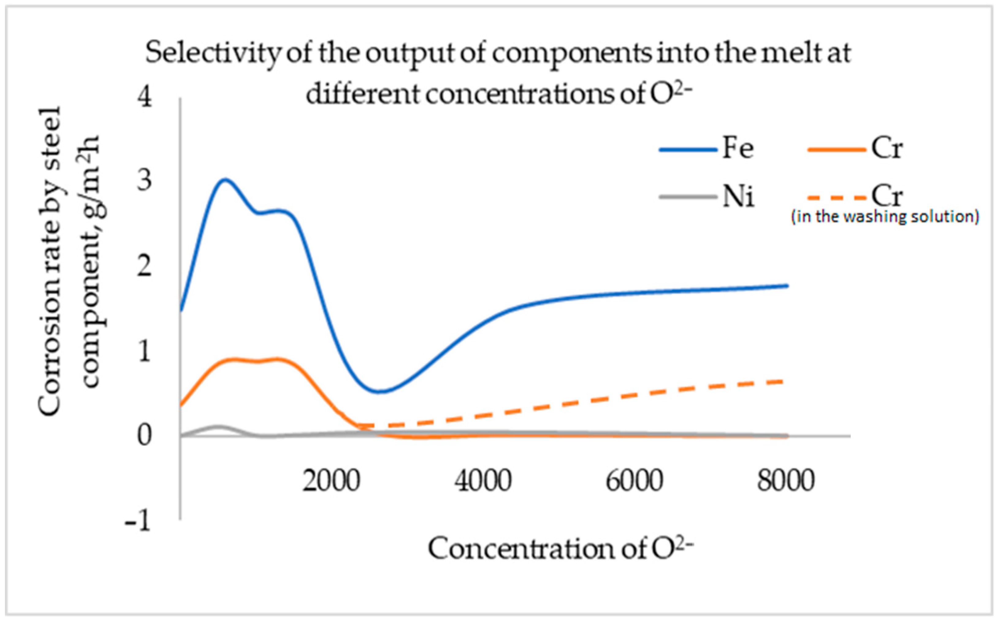
| Concentration O2− | Corrosion Rate, g/m2h | ||
|---|---|---|---|
| ppm | wt.% | According to Gravimetric Analysis | According to the Data of Elemental Analysis |
| <200 | <0.020 | 1.448 | 1.766 |
| 500 | 0.050 | 3.975 | 3.936 |
| 1000 | 0.100 | 3.717 | 3.516 |
| 1500 | 0.150 | 3.650 | 3.404 |
| 2500 | 0.250 | 0.162 | 0.541 |
| 4500 | 0.450 | 0.479 | 1.589 |
| 8000 | 0.800 | 0.943 | 1.705 |
Publisher’s Note: MDPI stays neutral with regard to jurisdictional claims in published maps and institutional affiliations. |
© 2022 by the authors. Licensee MDPI, Basel, Switzerland. This article is an open access article distributed under the terms and conditions of the Creative Commons Attribution (CC BY) license (https://creativecommons.org/licenses/by/4.0/).
Share and Cite
Karfidov, E.A.; Zaikov, Y.P.; Nikitina, E.V.; Seliverstov, K.E.; Dub, A.V. High-Temperature Passivation of the Surface of Candidate Materials for MSR by Adding Oxygen Ions to FLiNaK Salt. Materials 2022, 15, 5174. https://doi.org/10.3390/ma15155174
Karfidov EA, Zaikov YP, Nikitina EV, Seliverstov KE, Dub AV. High-Temperature Passivation of the Surface of Candidate Materials for MSR by Adding Oxygen Ions to FLiNaK Salt. Materials. 2022; 15(15):5174. https://doi.org/10.3390/ma15155174
Chicago/Turabian StyleKarfidov, Eduard A., Yuri P. Zaikov, Evgenia V. Nikitina, Konstantin E. Seliverstov, and Alexey V. Dub. 2022. "High-Temperature Passivation of the Surface of Candidate Materials for MSR by Adding Oxygen Ions to FLiNaK Salt" Materials 15, no. 15: 5174. https://doi.org/10.3390/ma15155174
APA StyleKarfidov, E. A., Zaikov, Y. P., Nikitina, E. V., Seliverstov, K. E., & Dub, A. V. (2022). High-Temperature Passivation of the Surface of Candidate Materials for MSR by Adding Oxygen Ions to FLiNaK Salt. Materials, 15(15), 5174. https://doi.org/10.3390/ma15155174