
Addition of Two Substantial Side-Branch Silencers to the Interference Silencer by Incorporating a Zero-Mass Metamaterial


Abstract
:1. Introduction
2. Measuring Equipment and Samples
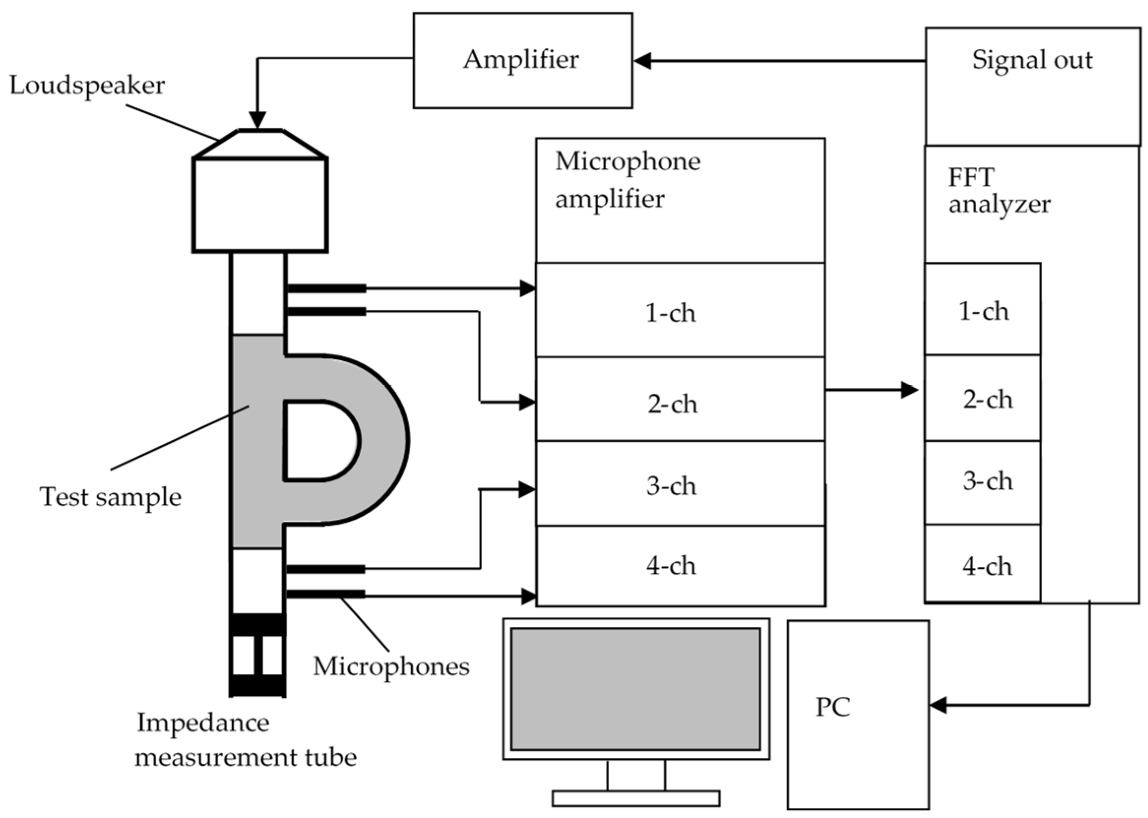
2.1. Transmission Loss Measurement
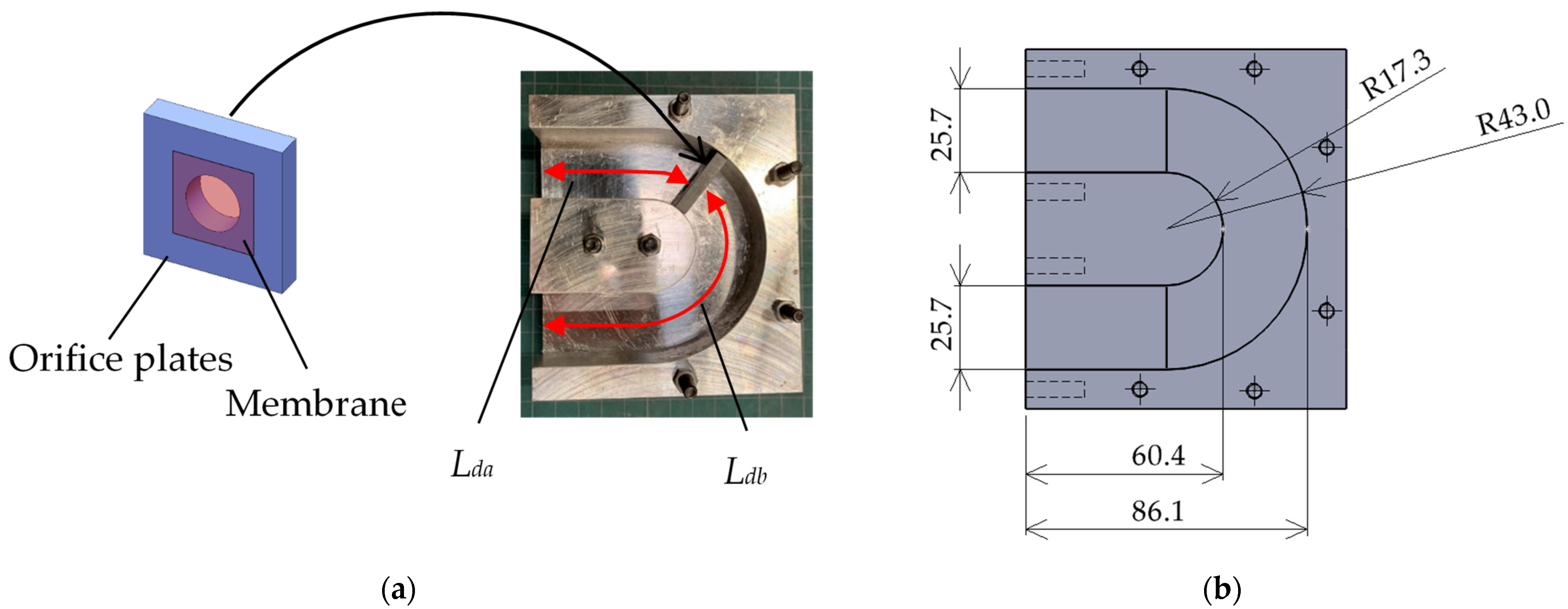
2.2. Zero-Mass Metamaterial and Delay Tube of Interferometric Silencer
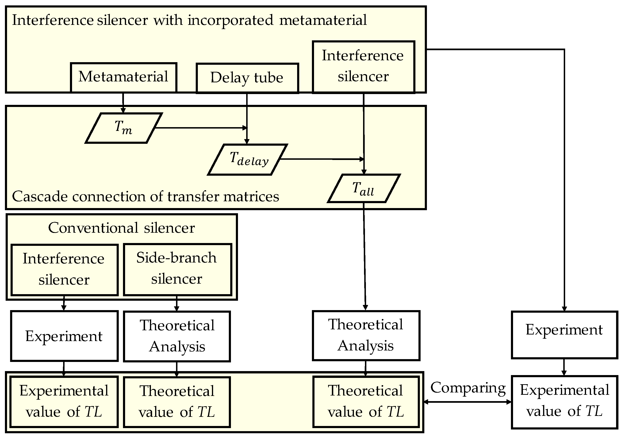
3. Theoretical Analysis
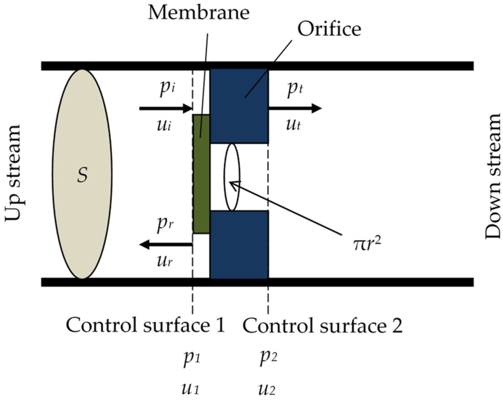
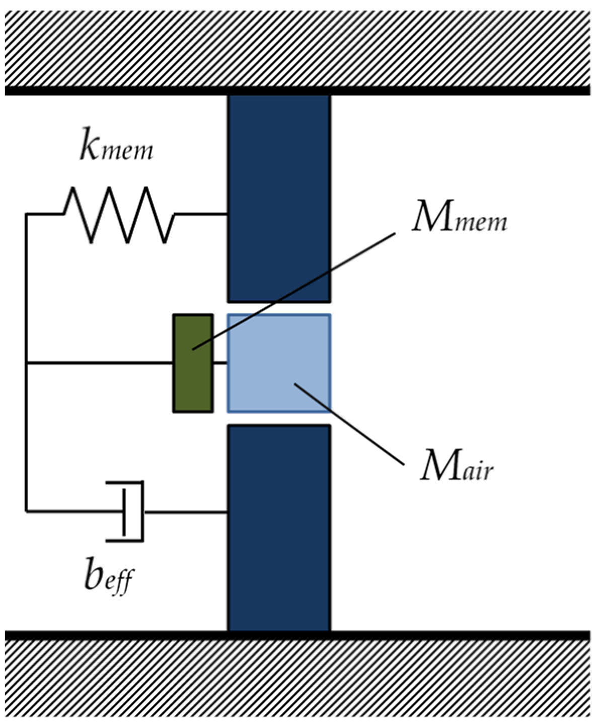
3.1. Analysis of Zero-Mass Metamaterial
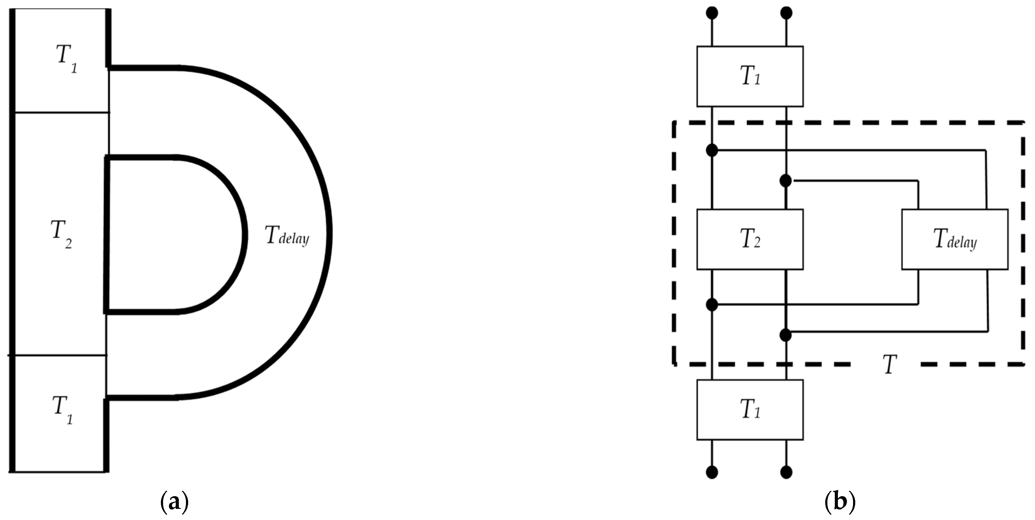
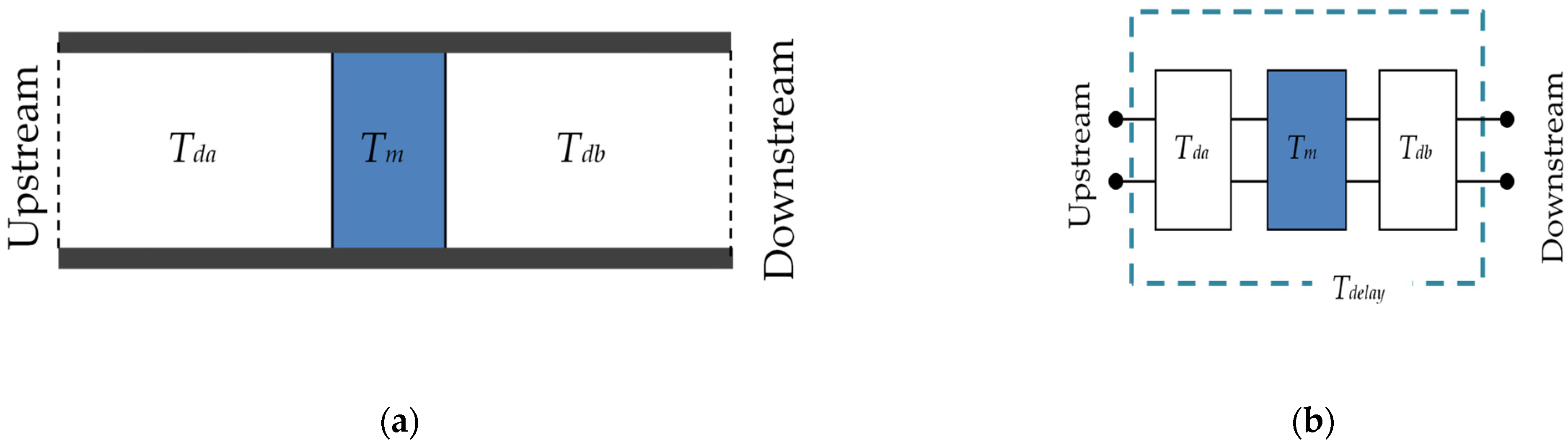
3.2. Theoretical Analysis of Delay Tube with Built-In Zero-Mass Metamaterials
3.3. Transfer Matrix for Entire Interference Silencer
3.4. Peak Frequency of Sound Attenuation for Ordinary Interference-Type Silencers and Side-Branch Silencers
4. Experimental and Theoretical Values for Transmission Loss
4.1. Transmission Loss of Single Zero-Mass Metamaterial
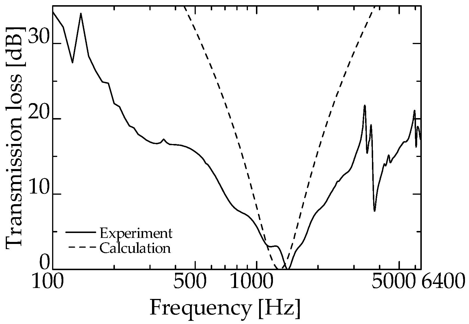
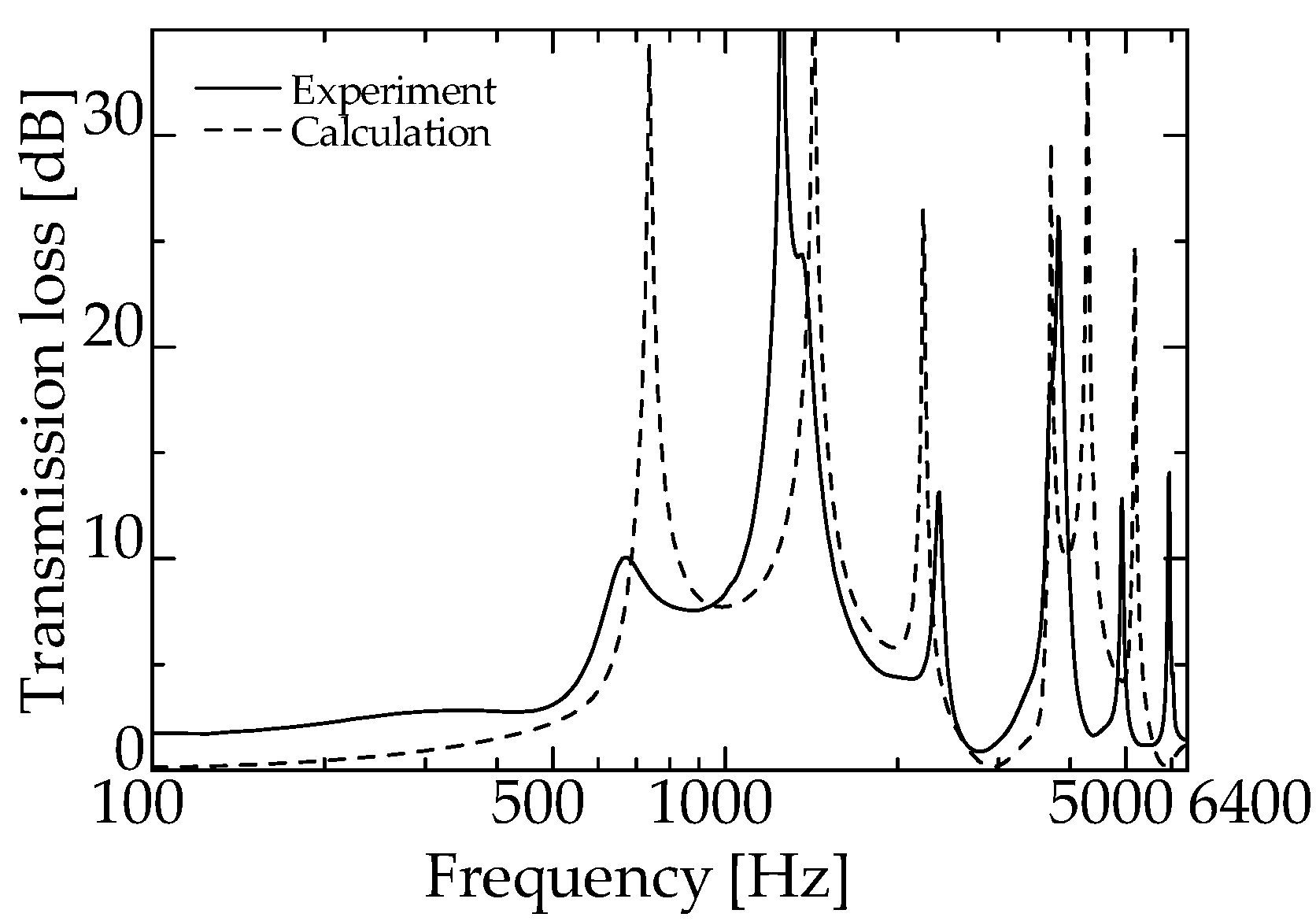
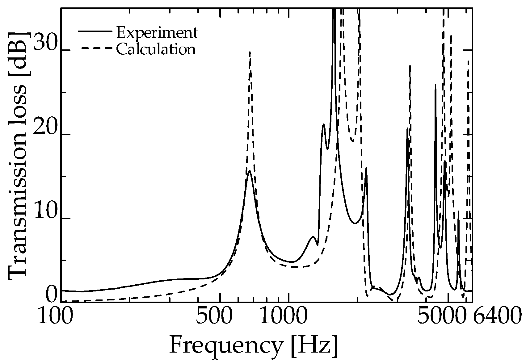
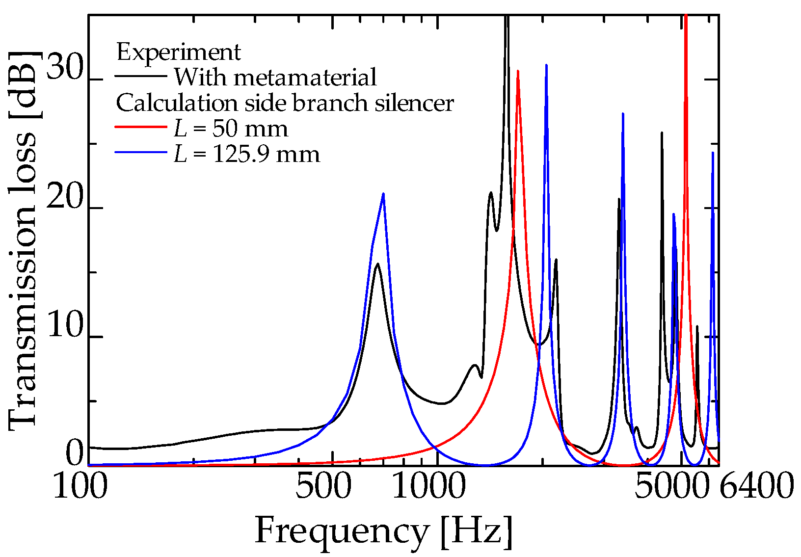
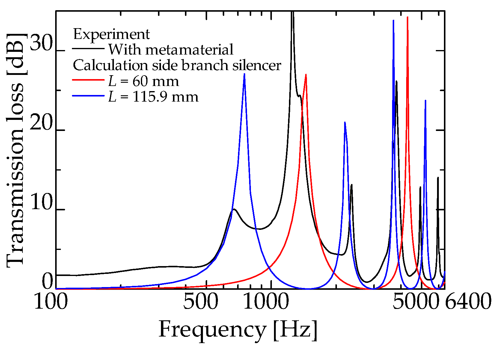
4.2. Comparison of Experimental and Theoretical Values
5. Conclusions
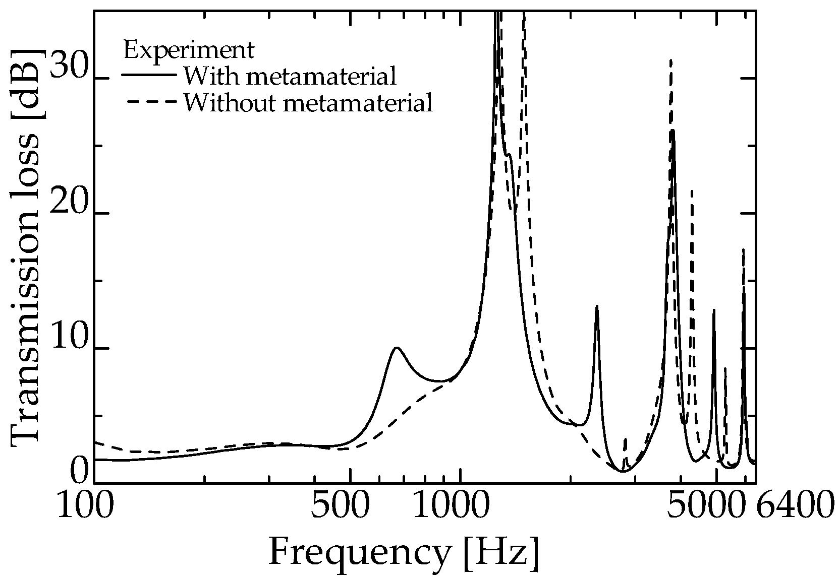
- The incorporation of zero-mass metamaterial into an interference-type silencer can introduce the silencing effect of a side-branch silencer with two different branch tube lengths without increasing the volume of the interference-type silencer. Consequently, the total volume of the interference and two side-branch silencers could be reduced by half.
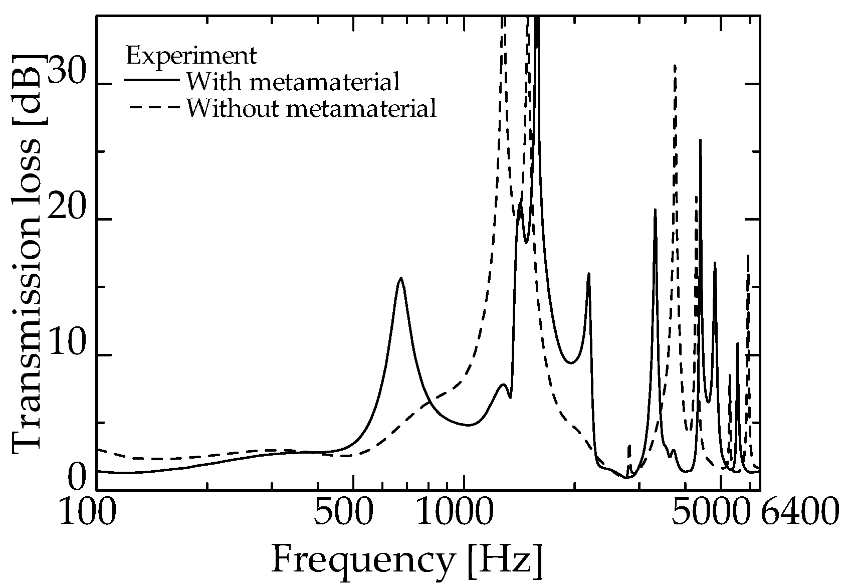
- The incorporation of zero-mass metamaterials in the interference silencer increased the sound reduction peaks.
- Theoretical analysis of the interference-type silencer with built-in zero-mass metamaterial was conducted using the Equations of motion, and theoretical values were obtained using the transfer matrix. Consequently, the theoretical and experimental values were close, enabling us to predict the TL of the proposed silencer.
Author Contributions
Funding
Institutional Review Board Statement
Conflicts of Interest
Nomenclature
| ASTM | American Society for Testing and Materials |
| A-D, Aall–Dall | Four-terminal constants |
| beff | Damping coefficient |
| c0 | Speed of sound in the air (m/s) |
| d | Orifice plate diameter (mm) |
| f, fpeak, fside | Peak frequency (Hz) |
| FFT | Fast Fourier transform |
| I | Imaginary unit |
| k | Wavenumber |
| kmem | Spring constant of the thin film (N/m) |
| Ld, Lda, Ldb, Lm, Lside | Length of the tube (mm) |
| Mair | Mass of the air in the orifice hole |
| Meff | Effective mass |
| Mmem | Mass of the membrane attached to the orifice hole |
| p1, p2, pi, pr, pt | Sound pressure (Pa) |
| r | Orifice hole radius (mm) |
| S | Cross-sectional area of the acoustic tube (mm2) |
| t | Orifice plate thickness (mm) |
| tm | Film thickness (mm) |
| T, T1, T2, T11, T12, T21, T22, Tall, Tb, Tdelay, Tf, Tm | Transfer matrix |
| TL | Transmission loss (dB) |
| u1, u2, ui, ur, ut | Particle velocity (m/s) |
References
- Park, J.J.; Lee, K.J.B.; Wright, O.B.; Jung, M.K.; Lee, S.H. Giant Acoustic Concentration by Extraordinary Transmission in Zero-Mass Metamaterials. Phys. Rev. Lett. 2013, 110, 244302. [Google Scholar] [CrossRef] [PubMed]
- Gric, T.; Eldlio, M.; Cada, M.; Pistora, J. Analytic solution to field distribution in two-dimensional inhomogeneous waveguides. J. Electromagn. Waves Appl. 2015, 29, 1068–1081. [Google Scholar] [CrossRef]
- Liu, J.; Guo, H.; Wang, T. A Review of Acoustic Metamaterials and Phononic Crystals. Crystals 2020, 10, 305. [Google Scholar] [CrossRef]
- Zangeneh-Nejad, F.; Fleury, R. Active times for acoustic metamaterials. Rev. Physics. 2019, 4, 100031. [Google Scholar] [CrossRef]
- Yang, Z.; Mei, J.; Yang, M.; Chan, N.; Sheng, P. Membrane-type acoustic metamaterial with negative dynamic mass. Phys. Rev. Lett. 2008, 101, 204301. [Google Scholar] [CrossRef] [PubMed]
- Fleury, R.; Alù, A. Extraordinary sound transmission through density-near-zero ultranarrow channel. Phys. Rev. Lett. 2013, 111, 055501. [Google Scholar] [CrossRef] [PubMed] [Green Version]
- Cummer, S.A.; Christensen, J.; Alù, A. Controlling sound with acoustic metamaterials. Nat. Rev. Mater. 2016, 1, 16001. [Google Scholar] [CrossRef] [Green Version]
- Langfeldt, F.; Kemsies, H.; Gleine, W.; von Estorff, O. Perforated membrane-type acoustic metamaterials. Phys. Lett. A 2017, 381, 1457–1462. [Google Scholar] [CrossRef]
- Wang, X.; Zhao, H.; Luo, X.; Huang, Z. Membrane-constrained acoustic metamaterials for low frequency sound insulation. Appl. Phys. Lett. 2016, 108, 041905. [Google Scholar] [CrossRef]
- Xiao, S.; Ma, G.; Li, Y.; Yang, Z.; Sheng, P. Active control of membrane-type acoustic metamaterial by electric field. Appl. Phys. Lett. 2015, 106, 091904. [Google Scholar] [CrossRef] [Green Version]
- Sasao, H. Introduction to Acoustical Analysis Using Excel-Analysis of Acoustical Structure Characteristics-(4) Analysis of Duct Silencer Using Excel. Air-Cond. Sanit. Eng. 2007, 81, 51–58. (In Japanese) [Google Scholar]
- Sasao, H. Introduction to Acoustic Analysis by Excel-Analysis of Acoustic Structure Characteristics-(2) Analysis of Sound Absorbing Structure by Excel. Air-Cond. Sanit. Eng. 2006, 80, 99–105. (In Japanese) [Google Scholar]
- Lee, S.H.; Park, C.M.; Seo, Y.M.; Wang, Z.G.; Kim, C.K. Acoustic metamaterial with negative density. Phys. Lett. A 2009, 373, 4464–4469. [Google Scholar] [CrossRef]
- Ingård, U. On the theory and design of acoustic resonators. J. Acoust. Soc. Am. 1953, 25, 1037–1061. [Google Scholar] [CrossRef]
- Benade, H.A. Measured end corrections for woodwind toneholes. J. Acoust. Soc. Am. 1967, 41, 1609. [Google Scholar] [CrossRef]
- Nakano, A. Noise control technology (3). J. Environ. Conserv. Eng. 1988, 17, 745–752. (In Japanese) [Google Scholar] [CrossRef]


| Material of Membrane | Nominal Density (kg/m3) | Measured Membrane Thickness (μm) |
|---|---|---|
| Low-density polyethylene | 920 | 11 |
| Material of Orifice | Thickness of Plate (mm) | Diameter of Hole (mm) |
|---|---|---|
| Photocurable resin | 5 | 10 |
| Element | Ratio (%) | Element | Ratio (%) |
|---|---|---|---|
| Aluminum | Balance | Copper | 0.10 max |
| Magnesium | 2.2–2.8 | Manganese | 0.10 max |
| Chromium | 0.15–0.35 | Zinc | 0.10 max |
| Silicon | 0.25 max | Others, each | 0.05 max |
| Iron | 0.40 max | Others, total | 0.15 max |
| Length of Side-Branch Tube Lside(mm) | |||||
| 50.0 | 60.0 | 125.9 | 115.9 | ||
| Peak Frequency fside (Hz) | n = 1 | 1701.5 | 1418.0 | 675.7 | 734.0 |
| n = 2 | 5104.5 | 4253.8 | 2027.2 | 2202.1 | |
Publisher’s Note: MDPI stays neutral with regard to jurisdictional claims in published maps and institutional affiliations. |
© 2022 by the authors. Licensee MDPI, Basel, Switzerland. This article is an open access article distributed under the terms and conditions of the Creative Commons Attribution (CC BY) license (https://creativecommons.org/licenses/by/4.0/).
Share and Cite
Sakamoto, S.; Shin, J.; Abe, S.; Toda, K. Addition of Two Substantial Side-Branch Silencers to the Interference Silencer by Incorporating a Zero-Mass Metamaterial. Materials 2022, 15, 5140. https://doi.org/10.3390/ma15155140
Sakamoto S, Shin J, Abe S, Toda K. Addition of Two Substantial Side-Branch Silencers to the Interference Silencer by Incorporating a Zero-Mass Metamaterial. Materials. 2022; 15(15):5140. https://doi.org/10.3390/ma15155140
Chicago/Turabian StyleSakamoto, Shuichi, Juung Shin, Shota Abe, and Kentaro Toda. 2022. "Addition of Two Substantial Side-Branch Silencers to the Interference Silencer by Incorporating a Zero-Mass Metamaterial" Materials 15, no. 15: 5140. https://doi.org/10.3390/ma15155140
APA StyleSakamoto, S., Shin, J., Abe, S., & Toda, K. (2022). Addition of Two Substantial Side-Branch Silencers to the Interference Silencer by Incorporating a Zero-Mass Metamaterial. Materials, 15(15), 5140. https://doi.org/10.3390/ma15155140