Article

Surface Functionalisation of Dental Implants with a Composite Coating of Alendronate and Hydrolysed Collagen: DFT and EIS Studies

1
Division of Materials Chemistry, Ruđer Bošković Institute, Bijenička cesta 54, 10002 Zagreb, Croatia
2
Division of Materials Physics, Ruđer Bošković Institute, Bijenička cesta 54, 10002 Zagreb, Croatia
3
Centre of Excellence for Advanced Materials and Sensing Device, Ruđer Bošković Institute, Bijenička cesta 54, 10002 Zagreb, Croatia
4
Division of Physical Chemistry, Ruđer Bošković Institute, Bijenička cesta 54, 10002 Zagreb, Croatia
5
Department of Electrochemistry, Faculty of Chemical Engineering and Technology, University of Zagreb, Marulićev trg 19, 10000 Zagreb, Croatia
6
Faculty of Physics and Center for Micro- and Nanosciences and Technologies, University of Rijeka, R. Matejcic 2, 51000 Rijeka, Croatia
7
Poliklinika Petković, Lašćinska cesta 97, 10000 Zagreb, Croatia
*
Authors to whom correspondence should be addressed.
Materials 2022, 15(15), 5127; https://doi.org/10.3390/ma15155127
Submission received: 27 May 2022 / Revised: 13 July 2022 / Accepted: 19 July 2022 / Published: 23 July 2022
(This article belongs to the Special Issue Bioactive and Functional Materials)

Abstract

:
The success of the osseointegration process depends on the surface characteristics and chemical composition of dental implants. Therefore, the titanium dental implant was functionalised with a composite coating of alendronate and hydrolysed collagen, which are molecules with a positive influence on the bone formation. The results of the quantum chemical calculations at the density functional theory level confirm a spontaneous formation of the composite coating on the titanium implant, ∆G*INT = −8.25 kcal mol−1. The combination of the results of X-ray photoelectron spectroscopy and quantum chemical calculations reveals the structure of the coating. The alendronate molecules dominate in the outer part, while collagen tripeptides prevail in the inner part of the coating. The electrochemical stability and resistivity of the implant modified with the composite coating in a contact with the saliva depend on the chemical nature of alendronate and collagen molecules, as well as their inter- and intramolecular interactions. The formed composite coating provides a 98% protection to the implant after the 7-day immersion in the artificial saliva. From an application point of view, the composite coating could effectively promote osseointegration and improve the implant’s resistivity in contact with an aggressive environment such as saliva.

Graphical Abstract

1. Introduction

The surface chemistry and properties are key factors of the implant’s long life since the surface of the implant is in direct contact with surrounding bones of the oral cavity [1]. Therefore, many commercially available implants made of metals, alloys, and ceramics have been intensively explored to evaluate their surface properties [2,3,4]. The results revealed the presence of inorganic and organic contaminants on many implants. To ensure appropriate implant’s surface characteristics, manufacturers use various surface treatments and processes such as high-temperature acid etching, anodising, sand and grit blasting, plasma spraying, or surface polishing [5,6,7,8]. For example, some studies have shown that rough implant surfaces favour the proliferation of bone-forming cells, or osteoblasts [7,8,9], which is why surface treatment with Al2O3 particles as abrasive agents is commonly used. Although the implants meet very strict international quality standards, Al2O3 particles and other contaminants can remain present on the implant’s surface.
It must not be forgotten that a human body, especially the oral cavity, is an aggressive environment containing different ions, enzymes, bacteria, and frequent daily pH changes. Such an environment can cause the release of contaminants from the implant’s surface into surrounding tissues and organs, which can trigger negative biological processes such as allergies or inflammation [10]. All this clearly underlines the need for improving the production process and introducing regular strict quality controls of implants. The chemical functionalisation of the implant’s surfaces is a simple way of improvement of surface properties, as well as resistivity of the implant during an exposure to the aggressive environment [1]. Biomimetic coatings [11] and coatings based on compounds with a positive effect on the bone system [12] have been in the focus of research in recent years. These coatings will behave as a barrier between the implant and the surrounding media, which can stop the release of contaminants from the implant into tissues and organs [13].
This study was focused on the titanium dental implant with detected aluminium (7 at.%). The main goal was to create a coating, which can improve overall resistivity of the implant during an exposure to the artificial saliva. Molecules of alendronate, a drug for bone diseases [12], and hydrolysed collagen, a biopolymer that provides structural and mechanical support to bones and connective tissues [14], were used for the functionalisation of the implant. A combination of results of X-ray photoelectron spectroscopy (XPS) and quantum chemical calculations at the density functional theory level (DFT) enabled a determination of a complex formation mechanism of the coatings. The influence of the coatings on overall electrochemical stability of the implants was explored by impedance spectroscopy (EIS) in the artificial saliva.

2. Materials and Methods

2.1. Chemicals, Solutions, and Materials

Solutions of hydrolysed collagen (Medex d.o.o., Slovenia) and sodium alendronate trihydrate (Merck Sharp & Dohme, Kenilworth, NJ, USA) were used to functionalise implants surfaces. The powders were dissolved in Milli-Q® water (Millipore, Merck, Darmstadt, Germany) to prepare a 10 mmol dm−3 solution of each compound. A mixed solution of hydrolysed collagen and alendronate was prepared as follows. The powder of the hydrolysed collagen was dissolved ultrasonically (f = 35 kHz; 10 min) in the alendronate solution (10 mmol dm−3). The final concentration of the collagen solution was 10 mmol dm−3.
Grade 2 titanium dental implants (Ankylos® C/X A11, Dentsply Friadent® GmbH, Baden-Wuerttemberg, Germany) [15] were used as substrates for surface functionalisation.

2.2. Functionalisation of the Implant Surfaces

Before coatings preparation, the surfaces of the as-received implants were ultrasonically degreased with acetone (p.a., Gram-Mol, Zagreb, Croatia) and absolute ethanol (p.a., Gram-Mol, Croatia). The samples were rinsed with Milli-Q® water, dried in a nitrogen stream (99.999%, Messer, Bad Soden, Germany), and immersed immediately in the prepared solutions at 22 ± 2 °C for 24 h. To ensure the chemical stability of the coatings on the implant’s surfaces, the modified samples were dried at 70 °C for 7 h after removal from the solutions [13,16]. Then, they were rinsed with Milli-Q® water and absolute ethanol and dried in a nitrogen stream. To evaluate the influence of the composite coating on the properties of the implant, it was necessary to investigate the influence of each composite component. Therefore, the implant surfaces were functionalised with alendronate, hydrolysed collagen, and composite coatings.

2.3. Characterisation of the Implants

The morphological characteristics and elemental analysis of the implant surfaces were studied by the field emission scanning electron microscope (SEM, model JSM-7000F, Jeol Ltd., Tokyo, Japan) in conjunction with the Oxford Instruments energy dispersive X-ray analyser EDS/INCA 350 at 10 kV.
The Raman spectra were recorded in the T64000 (HORIBA Jobin Yvon, Kyoto, Japan) triple Raman spectrometer with a 532 nm diode laser. The laser excitation power was 5 mW.
The attenuated total reflection Fourier transform infrared (ATR-FTIR) spectra were measured by the Frontier spectrometer (PerkinElmer, Waltham, MA, USA) from 4000 to 370 cm−1 with a resolution of 4 cm−1 and 16 scans per measurement. The results shown represent the average of three measurements.
The X-ray photoelectron spectroscopy (XPS) analysis was carried out in the SPECS instrument, using monochromatised Al Kα line of 1486.74 eV. For the measurements around Ti 2p, O 1s, and C 1s core levels, the pass energy of the electron energy analyser (Phoibos MCD 100) was set to 10 eV, while the pass energy of 20 eV was used for the measurements around N 1s core level. The experimental spectra were fitted with the product of Gaussian and Lorentzian functions with Shirley background subtraction [17]. The binding energy (BE) of all photoemission spectra was calibrated by the BE of the C 1s peak at 285.0 eV.
The electrochemical behaviour of the implants was investigated in a three-electrode cell (Metrohm, Autolab, Riverview, FL, USA) in the Fusayama artificial saliva solution (pH 6.8 [18]) over seven days. The uncoated and coated implant samples served as the working electrodes with an area of 0.98 cm2 exposed to the electrolyte. The Ag|AgCl, 3.0 mol dm−3 KCl (E = 0.210 V vs. standard hydrogen electrode, SHE) was used as reference and the platinum sheet as a counter electrode. The measurements were performed using electrochemical impedance spectroscopy (EIS) at the open circuit potential (EOCP) in the frequency range from 104 to 10−3 Hz with an ac amplitude of ±5 mV. The Solartron 1287 potentiostat/galvanostat with the FRA 1260 (Solartron Analytical, Farnborough, UK) controlled by the ZPlot® software (Southern Pines, NC, USA) was used for data acquisition. The ZView® software (Southern Pines, NC, USA) [19] was used for experimental data processing (χ2 values < 5 × 10⁻³).

2.4. Quantum Chemical Calculations

All the calculations were conducted at the DFT level in the Gaussian 09 (revision D.01) package [20]. Geometry optimisation was performed by the M06 functional developed by Truhlar’s group [21,22,23] and the 6-31+G(d,p) + LANL2DZ basis set. Pople’s 6-31+G(d,p) double-ξ basis set was chosen for the H, C, O, N, and P atoms, and the LANL2DZ basis set for the transition metal (Ti) atoms [24]. All the calculated structures were verified to be true minima on the potential energy surface at the same level of theory by the vibrational frequency analysis performed utilising the harmonic oscillator approximation. The thermal correction to the Gibbs free energy was derived from the same vibrational analysis. The energies were refined according to a highly flexible basis set for H, C, O, N, and P atoms, while the same LANL2DZ ECP type basis set was employed for titanium atoms. The polarizable continuum solvation model SMD, a solvation model based on density [25], was employed to account for the solvation effects. The value of a dielectric constant, ε = 78.3553 was taken for the simulation with water as solvent. The topological analysis of the charge density distribution applying Bader’s quantum theory of atoms in molecules (QTAIM) [26] was performed with the AIMALL [27] program package and utilizing the SMD/M06/6-31+G(d,p) + LANL2DZ wave function obtained from the optimisation.
All possible molecular surface/coating interactions were simulated by the (TiO2)10 nanocluster [28,29], whereas hydrolysed collagen was modelled by the functional glycine-proline-hydroxyproline tripeptide fragment, NH3+-Gly-Pro-Hyp-COO- [30], appearing in numerous extracellular matrix proteins as the most frequent collagen’s tripeptide unit. The Gibbs free energy of the interactions, ∆G*INT, was calculated using the supramolecular approach according to the formula ∆G*INT = G*ABG*AG*B, where G*AB is the total free energy of the resulting AB structure, and G*A and G*B are the total free energies of the associating units A and B, respectively (Tables S1 and S2 in the Supplementary Materials). A detailed description of the computational modelling is provided in the Supplementary Materials.

3. Results

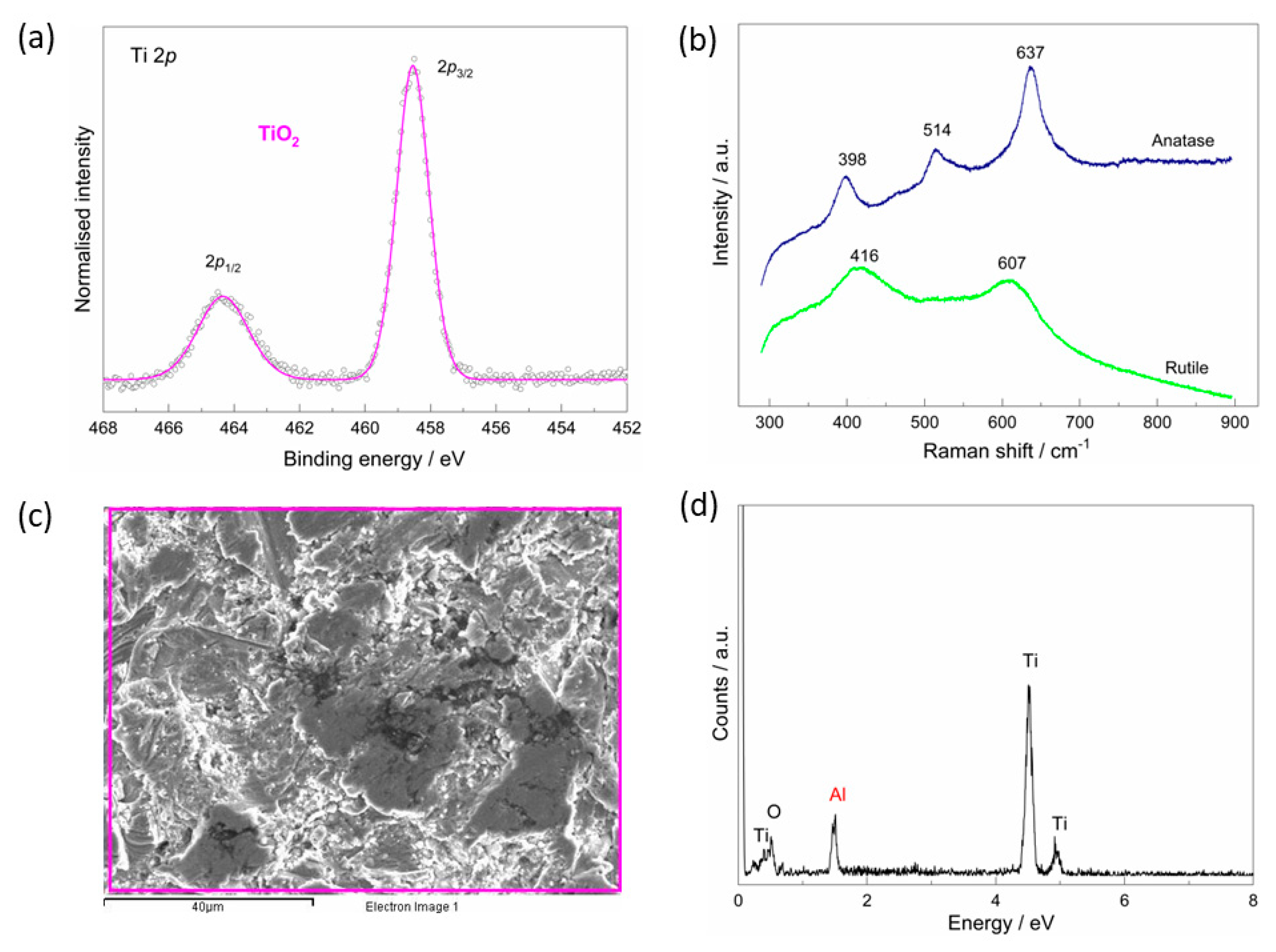
3.1. The As-Received Implant—Morphological, Chemical, and Phase Analysis

Chemical and phase composition and morphological features of the as-received implant were explored by SEM, EDS, Raman, and XPS techniques (Figure 1). The XPS spectrum around the Ti 2p core level (Figure 1a) confirms the presence of the TiO2 on the implant’s surface, which is evident from the spin-orbit doublet characterised by the 5.8 eV difference between Ti 2p3/2 (at the binding energy, BE of 458.5 eV) and Ti 2p1/2 [31,32].
The Raman spectroscopy reveals the presence of peaks corresponding to the anatase and rutile phases of the TiO2 (Figure 1b) that formed during the manufacturing process. The peaks at 398 (B1g), 514 (B1g), and 637 cm−1 (Eg) can be assigned to the anatase phase, while the peaks at 416 (Eg) and 607 (A1g) cm−1 correspond to the rutile phase [33,34]. In the case of the rutile phase, a shift of the Eg band is observed, which could be related to defects, crystallite size, or lattice strain [35,36].
The SEM shows that the TiO2 is inhomogeneous and microrough layer (Figure 1c) with detected aluminium probably remaining on the surface after the production process (Figure 1d).

3.2. The Chemical Characterisation of the Implant

An initial evaluation of the coating’s formation on the titanium implant surfaces was performed by ATR-FTIR spectroscopy (Figure 2). For comparison, the spectra of the starting chemicals, alendronate sodium and hydrolysed collagen, are shown. In addition, all spectra are compared with the vibrational spectra calculated by DFT (Supplementary Materials Figure S1).
The IR spectra of the alendronate and the implant/alendronate samples (Figure 2a) exhibit a characteristic P−O and P=O region (~1200–900 cm−1), and the phosphate band at 1520 (1516) cm−1 characteristic for the alendronate [37,38]. The bands are slightly altered by the interaction between alendronate and implant’s surface. The effect of alendronate adsorption is most pronounced in the high wavenumber region resulting in the absence of the NH2 band (around 3580 cm−1). A wide band in the range between ~800 and 400 cm−1 (marked with *) can be assigned to the TiO2 layer vibration according to the DFT spectrum (Figure S1). This band appears in the spectra of all implant samples. The result is in accordance with the results of XPS and Raman that confirmed the existence of the TiO2 on the implant surface (Figure 1a,b).
The spectrum of the hydrolysed collagen (Figure 2b) shows characteristic bands of peptide binding vibrations: amide I (stretching vibration of −C=O of amide group at 1631 cm−1), amide II (N−H stretching coupled to the C−N stretching of amide group at 1522 cm−1), and amide III (C−N stretching and N−H in-plane bending of amide linkage at 1240 cm−1) [39,40,41]. The vibrations of amide IV (ν(C−C) and δ(O−C−N) at 540 cm−1) and amide V (δ(N−H) at 670 cm−1) are also visible [40,41]. The presence of water molecules forming hydrogen bonds with collagen molecules is reflected in the bands of amide A (ν(−OH) at 3280 cm−1) and amide B (ν(N−H stretching) at 3067 cm−1) [40]. The bands in the range 1400–1200 cm−1 (marked with +) can be assigned to the CH2 wagging vibrations of glycine and proline [39]. The functionalisation of the implant by the hydrolysed collagen resulted in the disappearance of some bands, the change in the intensity of the bands, and the shift of the peaks to higher wavenumbers, as can be seen in Figure 2b. Hydrogen bonds and conformational changes (confirmed by DFT, Section 3.3), which are characteristic of the collagen molecule, influence the shift of the bands. All this indicates successful adsorption of the hydrolysed collagen molecules on the implant’s surface.
The bands of the collagen peptide bond and the P−O and P=O bonds characteristic for the alendronate are visible in the spectrum of the implant/composite coating, Figure 2c. All spectra confirm that the coatings have successfully formed on the implant surfaces.
The XPS spectra around the Ti 2p core levels for all samples examined (Figure 3) reveal a structure of Ti atoms in the TiO2 compound characterised by a well-separated Ti 2p3/2 and Ti 2p1/2 spin-orbit doublet with the Ti 2p3/2 component at BE of 458.5 eV and the energy separation of 5.8 eV between the two peaks [31]. The result is in good agreement with the Raman spectra of the as-received implant (Figure 1b), which confirm the presence of TiO2 on the implant’s surface.
On the other hand, the different structure of the XPS peaks found in different samples around C 1s, O 1s, and N 1s core levels reflects the differences in atomic chemical bonding of the organic coatings studied in the present work (Figure 3). Thus, as assigned in our previous work [13], the three main contributions found in the C 1s spectrum of the alendronate-coated implant, are related to the C–C (285.0 eV), C–N (286.0 eV), and P–C–O (286.6 eV) bonds [42], while the low-intensity peaks at the higher BE side of the C 1s curve are attributed to surface oxygen contamination (O–C=O, C=O; see Figure 3a). In contrast, the C 1s spectra of the implants coated with the hydrolysed collagen and the composite coating (Figure 3b,c) show a quite different structure, with the intense peaks at BEs of 288.2 eV and 289.5 eV attributed to C=O and O–C=O bonds, respectively [43,44].
The deconvoluted N 1s spectrum of the alendronate-modified implant shows the two distinguished components, related to the nitrogen atoms in the C–NH2 bond (400.0 eV) and the N atoms bonded to the Ti atoms of the implant (398.5 eV), as shown in Figure 3a [12,13]. While the C–NH2 component is present in the N 1s spectra of the implants coated with the hydrolysed collagen and the composite coatings, no contribution from nitrogen bonded to the implant was observed in these two samples. This strongly suggests that the –NH2 group remained free and unbounded to the TiO2-covered implant and, therefore, can influence the surface properties of the implants modified with hydrolysed collagen and composite coatings. The peak at BE of 398.0 eV can be related to the N–C bond in the collagen molecule [43,44]. The intense peak (marked with *) at the higher BE side of the N 1s peak of the sample modified with composite coating can be attributed to surface contamination in the form of oxidised nitrogen species [45].
Turning now to the photoemission spectra around O 1s atomic levels in alendronate and collagen molecules (Figure 3a,b), the three characteristic fitting components were assigned to oxygen bonded in O=P/O=C (532.4 eV), HO–P (533.7 eV) and HO–C (534.3 eV) configuration [13,46,47], in addition to the O atoms bonded to titanium (peak at BE of 531.0 eV) [13,46]. Some additional contributions are visible in the O 1s spectra (marked with *), reflecting the presence of surface species, most likely in the form of adsorbed water molecules [48] or fluorine contamination [49].

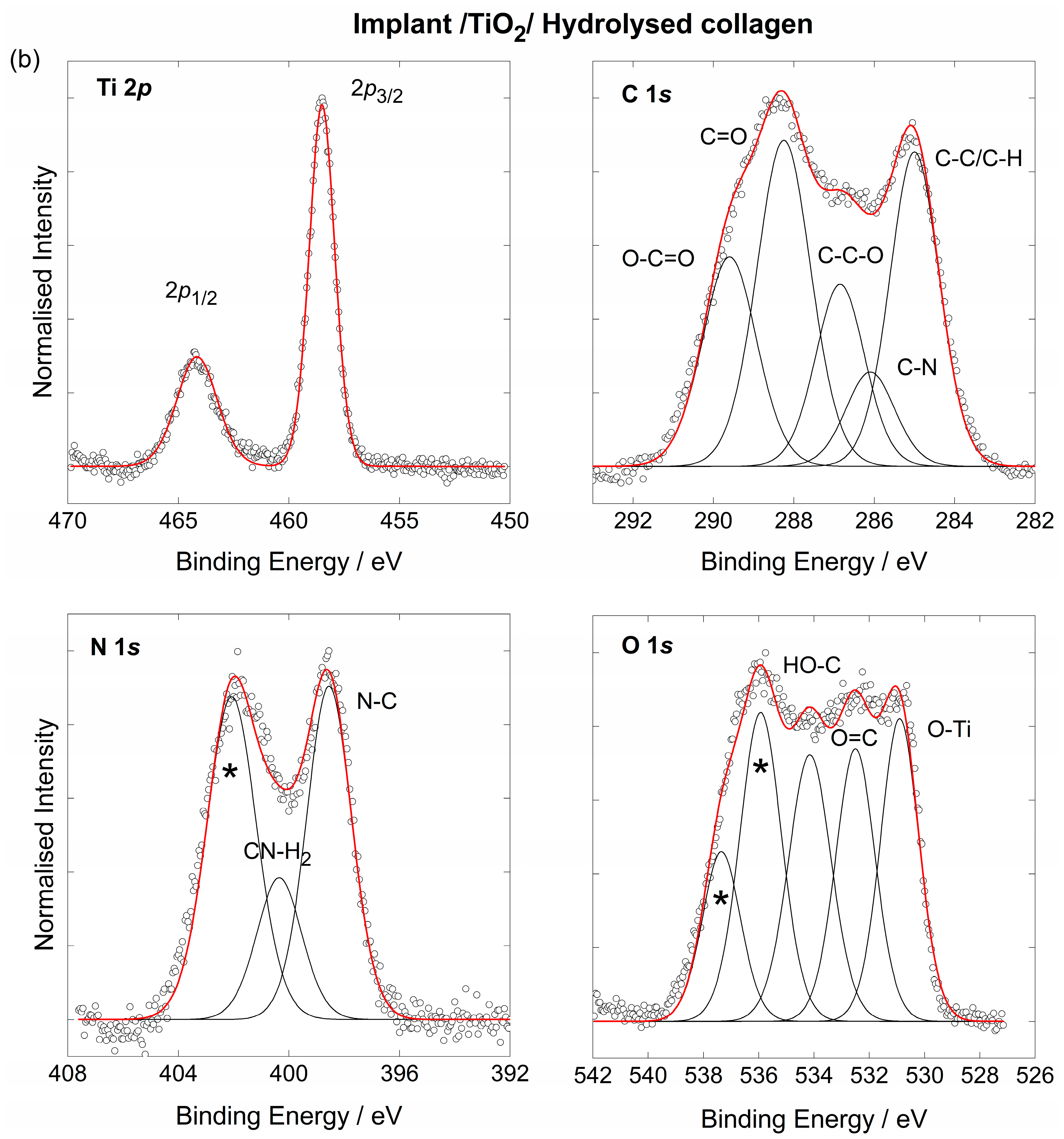
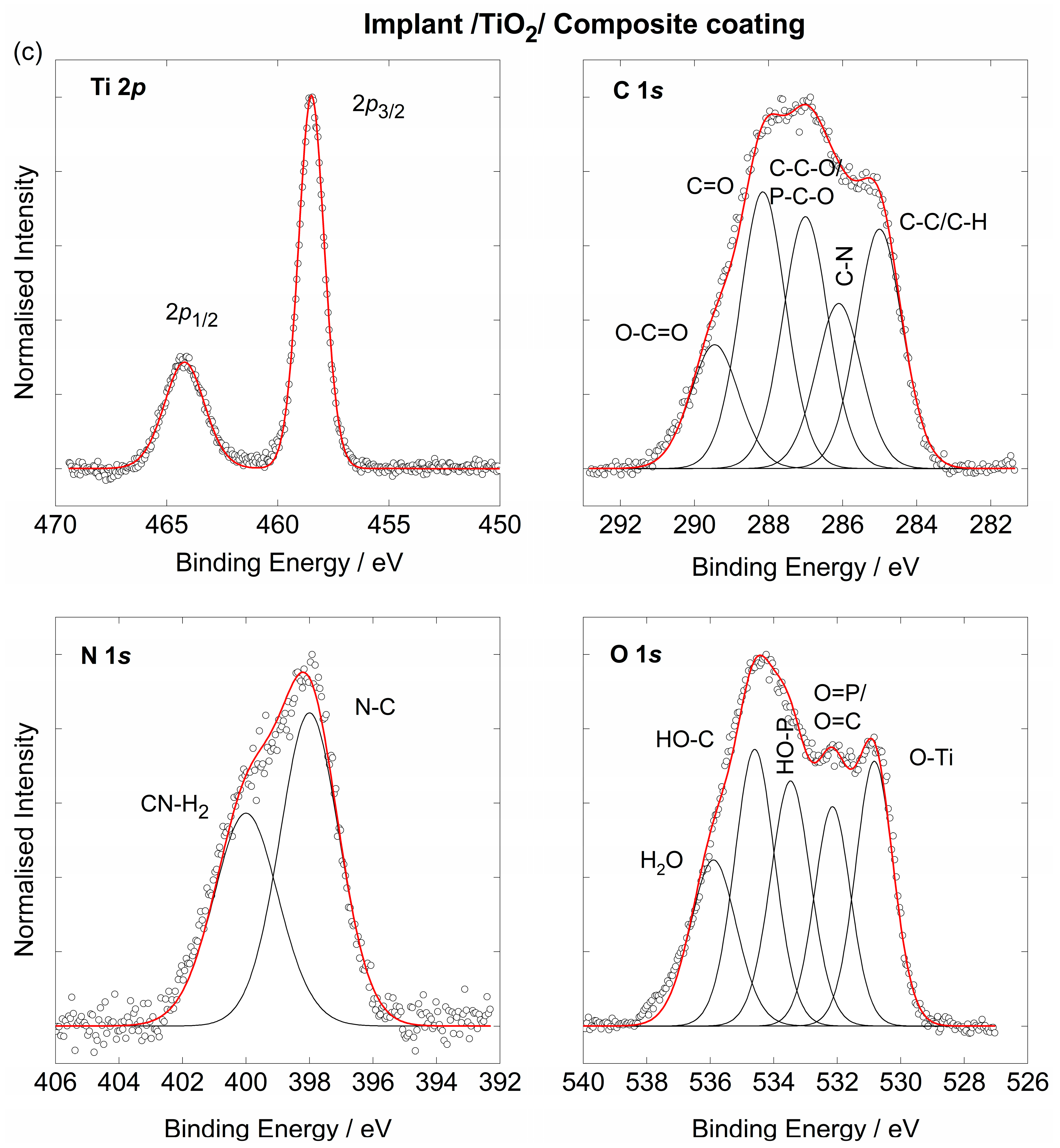
3.3. The Coating’s Formation Mechanism on the Implant

To understand the coating’s formation mechanism between the TiO2-covered implant and the selected coating molecules, a detailed theoretical study using quantum chemical calculations at the density functional theory (DFT) level was performed. The small (TiO2)10 nanocluster was used for cluster modelling of the titanium surface [29], while hydrolysed collagen was modelled by the functional glycine-proline-hydroxyproline tripeptide fragment, NH3+-Gly-Pro-Hyp-COO [30].
The large difference in the values of Gibbs free energies obtained for the most stable (TiO2)10—alendronate (∆G*INT = −13.64 kcal mol−1; Figure 4a,b) and (TiO2)10—tripeptide (∆G*INT = −6.45 kcal mol−1, Figure 4c) molecular interactions suggests a more spontaneous formation of the alendronate coating on the titanium implant. The most stable (TiO2)10—tripeptide structure is the result of two coordinate Ti–O bonds (C–O–Ti) additionally accompanied by hydrogen bonds (Figure 4c). The formation of the (TiO2)10—alendronate coating is most likely the result of two energetically competitive structures, one in which the alendronate molecule is bound to the surface via both the amine (–NH2) and phosphonate (–PO3H) groups (∆G*INT = −13.64 kcal mol−1), and the other in which the alendronate molecule is bound via the phosphonate (–PO3H) group (∆G*INT = −10.16 kcal mol−1; Figure 4a,b) [13]. All the structures described above are additionally stabilised by hydrogen bonds.
Two different strategies were used to model molecular interactions between the TiO2 layer on the implant and the composite coating molecules. One of the strategies is to model the composite component molecules simultaneously, and the other is to gradually add component molecules during the interaction simulation calculation. The results of the second approach, provided in the Supplementary Materials (Section B), yielded in less stable configurations (higher ∆G*INT values). In the case when tripeptide and alendronate molecules are taken into account simultaneously during the DFT calculation, the formation of the composite coating occurs most likely through two energetically competitive structures. In one the tripeptide unit of the collagen is bound to the TiO2 layer as the inner part of the coating, while alendronate is oriented toward the outer part of the coating ((TiO2)10—tripeptide—alendronate, ∆G*INT = −8.25 kcal mol−1; Figure 5a). The bonding between tripeptide and TiO2 surface occurs via two strong coordinate (C–O–Ti) bonds of the amino acid branches (dTi–O value up to 2.105 Å, ETi–O value up to −24.51 kcal mol−1) supported by one N–H∙∙∙O (dO∙∙∙H = 1.719 Å, EO∙∙∙H = −10.34 kcal mol−1) and three C–H∙∙∙O hydrogen bonds (dO∙∙∙H value up to 2.325 Å, EO∙∙∙H value up to −3.24 kcal mol−1). In the other structure, the alendronate molecule is bound to the titanium surface via phosphonate group (–PO3H) as the coating’s inner part with tripeptide as the coating’s outer part ((TiO2)10–alendronate─tripeptide; ∆G*INT = −6.03 kcal mol−1; Figure 5b). The bonding occurs via coordinate (P–O–Ti) bond, (dTi–O= 1.962Å, ETi–O = −38.99 kcal mol−1) supported by two O–H∙∙∙O hydrogen bonds, Figure 5b. The coordinate Ti–O bonds are attributed to an ionic type of interaction according to ∇2ρ(rc) > 0 and H(rc) > 0.
It is important to point out that weak intermolecular interactions between alendronate and tripeptide occur immediately at the beginning of the coating process forming an initiating linker or “coating directing agent”, Figure 5c. Due to a lower flexibility influenced by the presence of three hydrogen bonds O–H∙∙∙O, N–H∙∙∙O, and C–H∙∙∙O, alendronate molecules as part of the coating can only participate in the interactions with the phosphonate group (Ti–O), as shown in Figure 5b. For this reason, to model the (TiO2)10—alendronate—tripeptide structure, the less stable (TiO2)10—alendronate structure (Figure 4b) is used. Most likely, the composite coating formation is a result of both structures (Figure 5a,b) that would compete energetically and provide pronounced dynamics of a formation process.

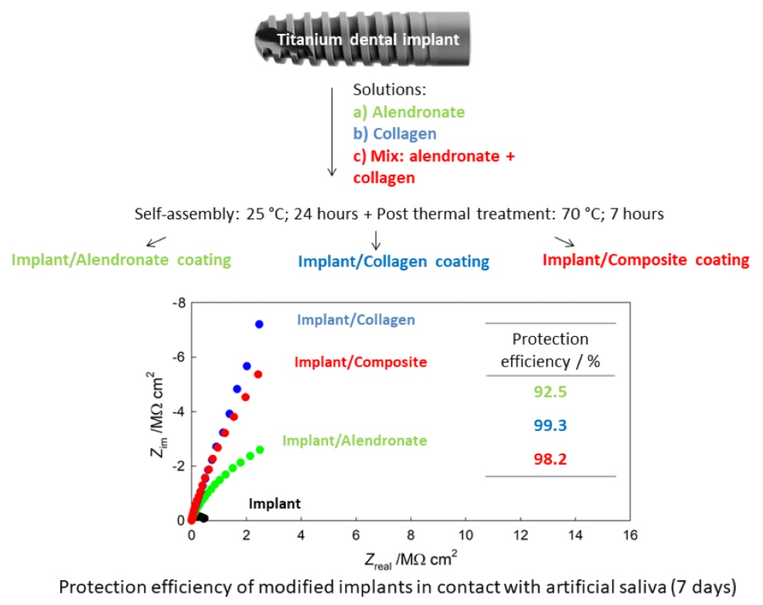
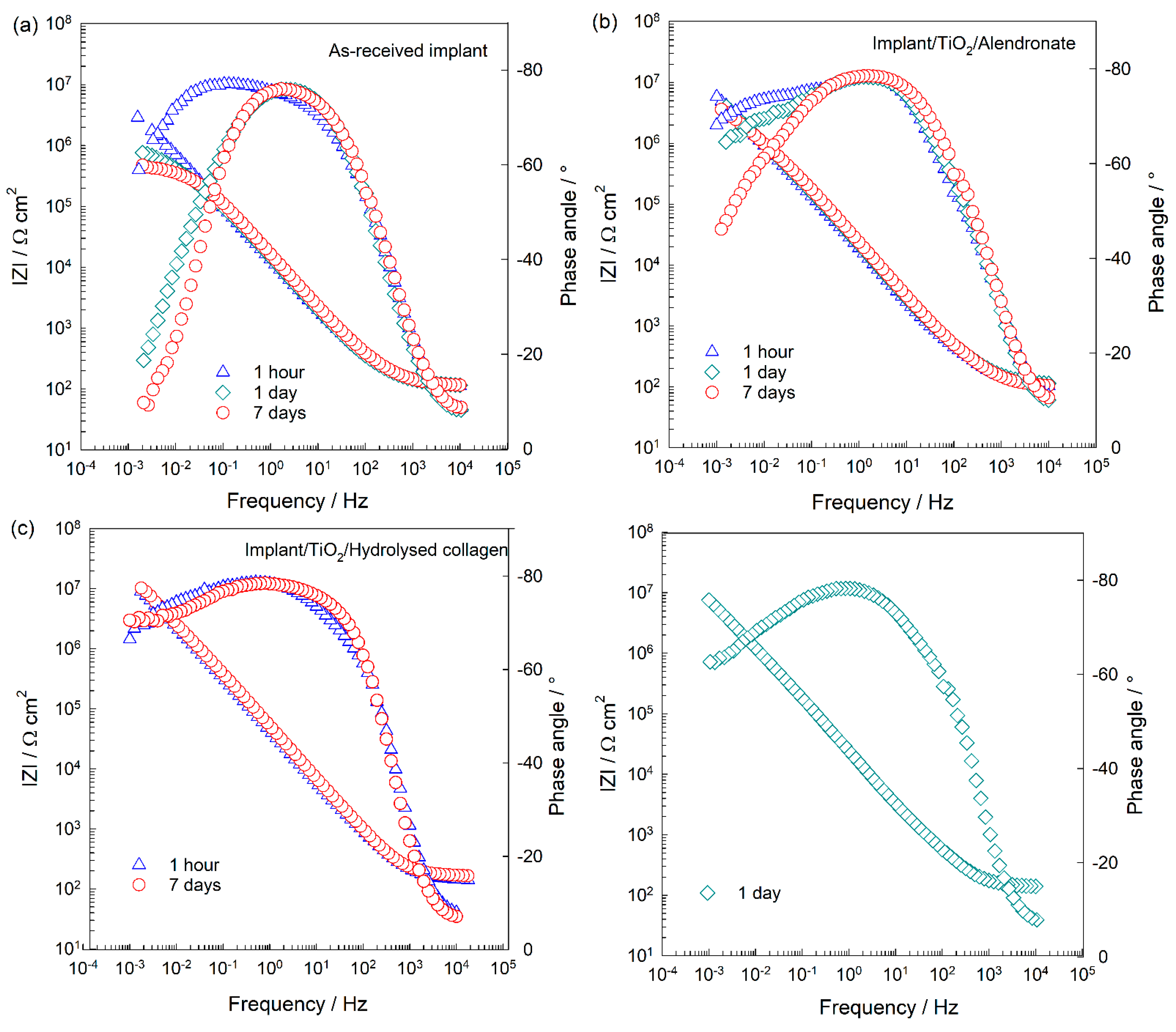
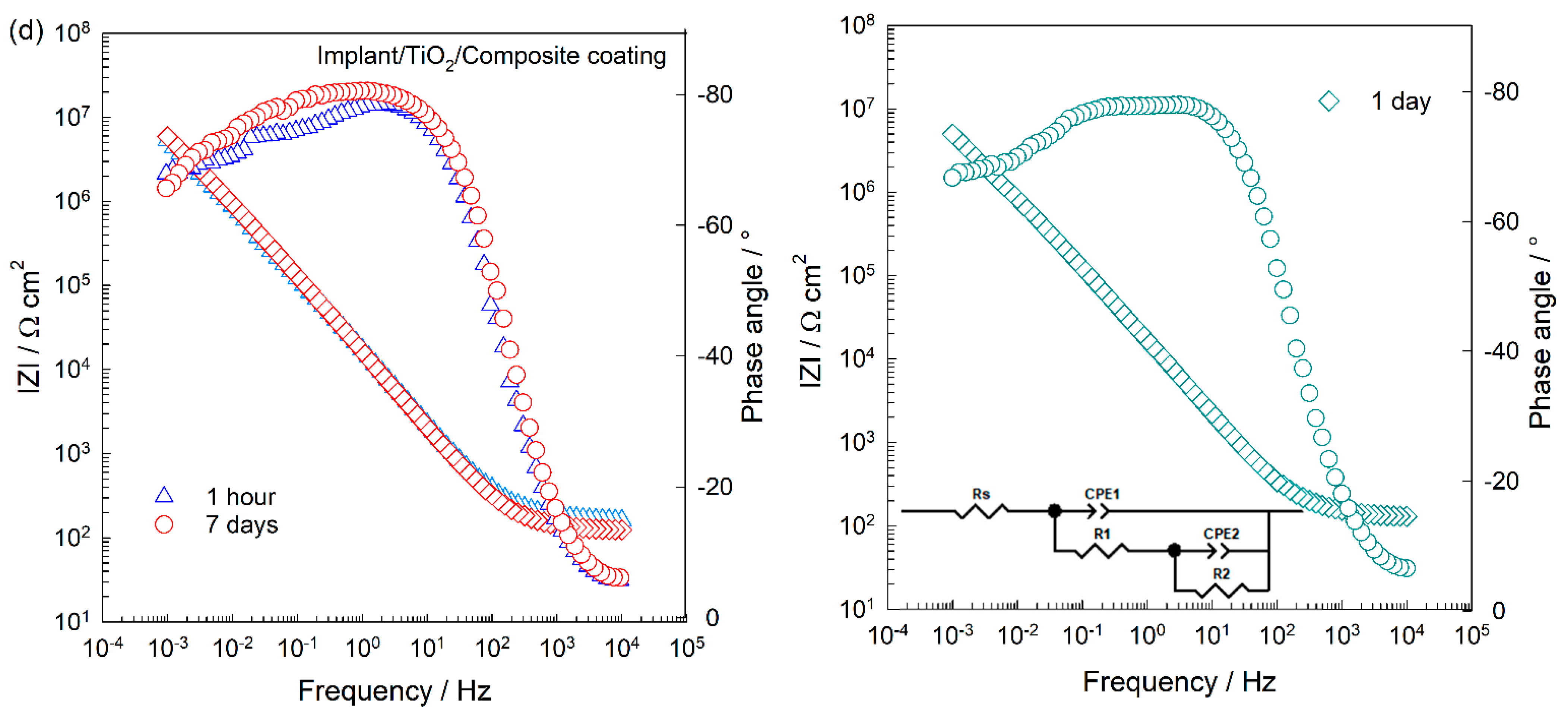
3.4. The Electrochemical Behaviour of Implants in Artificial Saliva Solution

The electrochemical investigations of the implants were carried out at the open circuit potential (EOCP) over 7 days of immersion in artificial saliva solution (1 h to 7 days). The results are shown in the form of the Bode plots (Figure 6), while the Nyquist plots are shown in the Supplementary Materials (Figure S3).
The structure of the electrified implant/artificial saliva interface can be described by an electrical equivalent circuit (EEC) with two time constants that are characteristic for a two-layer oxide film, TiO2 (inset in Figure 6d) [48,49]. Modelling results are given in Table 1. Due to the microscopic inhomogeneities of the studied system, a constant phase element (CPE) was used instead of a capacitor (C) [50,51]. The interfacial capacitance (C) values were calculated using Brug’s equation [51]. Rs is the electrolyte resistance.
The high-frequency time constant (R1CPE1) is related to the resistance (R1) and capacitance (CPE1) of the outer porous part of the oxide film, while the low-frequency time constant (R2CPE2) is related to the resistance (R2) and capacitance (CPE2) of the inner barrier part of the oxide. After 1 h of immersion in the artificial saliva (Figure 6a), the as-received implant possesses good protective properties, which can be attributed to the inner part of the TiO2 (R2 is higher than R1). Gradually, the protective properties of the oxide deteriorated and after 7 days of immersion, the R2 value decreased by ~23 times. Since R2 values are related to pores of the outer part of the oxide, obviously the density and/or size of pores increases with time allowing for ion/water diffusion from the solution deeper into the oxide. Consequently, R2 values decrease with time.
To improve the chemical stability of the implants, alendronate, hydrolysed collagen, and composite coatings were formed as additional barriers on the TiO2-covered implant surfaces, and their EIS spectra are presented in Figure 6b–d. A brief inspection of the EIS responses shows that all coatings have a positive effect on the protective properties of the implants (higher values of log |Z| versus log f compared to the values of the as-received implant; Figure 6), but their structural properties are different. The implant/TiO2/coating/saliva interface is described by the same EEC with two time constants, and the modelled values are listed in Table 1. The high/middle-frequency time constant (R1CPE1) is related to the resistance and capacitance of the surface film (organic coating over TiO2), while the low-frequency time constant (R2CPE2) is related to the resistance and capacitance of film structural defects [52]. The polarisation resistance, Rp [53] as a direct measure of material’s corrosion protection, is the sum of the values of R1 and R2 and allows for a calculation of the anti-corrosion effectiveness of the coated implant samples, η; η = (Rp,modifiedRp,unmodified)/Rp,modified. Rp,modified is the polarisation resistance of the coated implant and Rp,unmodified of the as-received implant.
In the case of the alendronate-modified implant, its protective properties and stability slightly decrease over time. The alendronate coating contains structural imperfections, pores that are visible from the phase angle (θ ˂ 90°), and n2 values (n2 ˂ 1). Decrease of the n2 values with time points to the propagation, additional occurrence of pores, and/or desorption of the molecules, which is induced by the hydrophilic character of the alendronate coating [13]. Structural defects influence negatively on the resistivity of the implant. Therefore, the R2 decrease is connected directly with the coating’s defects. The alendronate coating provides 92% protection to the implant during the 7-day immersion to the saliva.
The coating of the hydrolysed collagen provides a high protection of 99% to the implant during 7-day immersion in the saliva (Figure 6c). However, after 1 day of immersion, a sharp decrease of the R2 value occurs. Obviously, a contact of the coating´s unbonded functional groups with the ions of the electrolyte initiates a restructuring and the compactness of the coating is impaired. Once the peptide chains are reassembled into the stable and compact structure (DFT, Figure 4c), the R2 value increases again, Table 1.
The EIS responses of the implant functionalised with the composite coating remain almost unchanged during the 7-day immersion to the artificial saliva (Figure 6d). The interaction of the coating with the saliva is pronounced in the first day of the immersion when the coating reaches a less compact structure (reflected in θ versus log f). Consequently, R2 values decrease. Inter- and intramolecular interactions present in the composite coating (Figure 5a,b) enable a fast reorganisation of molecules resulting in the compact and stable structure (n2 and R2 values increase slightly).

4. Discussion

Although the implant used in this study was covered with the protective TiO2 layer (confirmed by Raman and XPS; Figure 1b,c), its protective properties deteriorated during a short period of 7-day immersion in the artificial saliva (Figure 6a). Since an aggressive environment such as saliva can induce a degradation of the implant, dissolution, and release of metal ions in the surrounding organs, it was attempted to improve the protective properties of the implant by means of the surface coatings formation.
The DFT calculations (Figure 4 and Figure 5) showed that the formation of all types of coatings investigated is spontaneous and ATR-FTIR (Figure 2) and XPS (Figure 3) confirmed their existence on the TiO2-covered implant surface.
The correlation of the DFT and XPS results enabled the determination of all possible molecular interactions and binding pathways of molecules to the implant’s surface. The knowledge of inter- and intramolecular interactions between coating molecules and the implant was essential for the understandings of the electrochemical behaviour of modified implants in the artificial saliva (Figure 6). Although all prepared coatings clearly showed a positive influence on the stability and resistivity of the implant in comparison to the unmodified implant, EIS results revealed structural finesses of the coatings responsible for the electrochemical stability of the modified implants.
The alendronate coating showed the most decreased protection in the artificial saliva (Figure 6b) among all coatings, although the interactions between implant and alendronate molecules are the most stable according to the DFT (Figure 4 and Figure 5). The surface of the implant modified with the alendronate is hydrophilic due to the presence of free hydrophilic functional groups –NH2, –COH, and –PO3H in the outer part of the coating (Figure 4a,b). It is well known that the hydrophilicity of the material has a negative effect on corrosion protection due to possible interactions with molecules/ions from electrolytes [13,52]. These interactions can cause a structural reorganisation of the coating, its desorption, and/or occurrence of defects that enable a penetration of ions from electrolytes to the underlying implant. As a result, corrosion protection and stability of the implant are reduced.
A high protection efficiency of the implant in the artificial saliva was achieved by the coating of the hydrolysed collagen (Figure 6c). The hydrolysed collagen as a biopolymer tends to form a crosslinking network, which includes various non-covalent, hydrophobic, and ionic interactions, as well as hydrogen and coordination bonds (DFT, Figure 4c). Furthermore, peptide chains of the hydrolysed collagen are broken into smaller parts that tend to organise into fibrils and are further stabilised through hydrogen bonding and crosslinking [14,54] All the interactions result in a compact structure of the coating and maintain its stability during the exposure of the implant to the saliva solution (Figure 6c).
The composite coating is most likely bound complexly to the implant via two stable structures (Figure 5a,b), which behave differently in contact with the saliva solution. If alendronate molecules are at the outer interface implant/coating/saliva (Figure 5a), restructuring of the coating can occur due to the interactions between the free hydrophilic groups (–NH2 and –PO3H) of the alendronate and the water/ions of the saliva. There is also a possibility that the alendronate molecules are desorbed from the implant. Consequently, the collagen layer of the coating will restructure. If collagen molecules are at the outer interface implant/coating/saliva (Figure 5b), the organisation of peptide chains in fibrils and/or their crosslinking can occur. All possible interactions reflect positively on the stability and protection of the implant in contact with the artificial saliva (Figure 6d).
From an application point of view, the composite coating of alendronate and hydrolysed collagen would be optimal for the functionalisation of the implant. Its high corrosion protection and stability are basic prerequisites for a successful long life of implants in the oral cavity. The combination of alendronate, a strong osteoinductive molecule, and collagen, a biopolymer that provides structural and mechanical support to bone and connective tissue, could induce and accelerate the osseointegration of the implant in the human body. The influence of the implant prepared in this way on long-term corrosion protection and the process of osseointegration needs to be investigated in the future.

5. Conclusions

The coatings of alendronate sodium and hydrolysed collagen, as well as the composite coating, were formed successfully by self-assembly process on the titanium dental implants.
The Raman and XPS analyses reveal the presence of TiO2 in the form of rutile and anatase phase on the implant’s surface.
In addition, the DFT results show that the molecular interactions between the TiO2-covered implant surface and the organic molecules were spontaneous (∆G*INT < 0). The value of the Gibbs free energy is the most stable for (TiO2)10─alendronate ∆G*INT = −13.64 kcal mol−1, for (TiO2)10─tripeptide ∆G*INT = −6.45 kcal mol−1, and for (TiO2)10─tripeptide─alendronate ∆G*INT = −8.25 kcal mol−1.
Furthermore, the structure of the alendronate coating is the result of two energetically competitive structures. The bonding occurs via the amine (–NH2) and the phosphonate (–PO3H) groups (∆G*INT = −13.64 kcal mol−1), and/or only via the phosphonate (–PO3H) group (∆G*INT = −10.16 kcal mol−1). Hydrophilic (–NH2), (–COH), and (–PO3H) groups in the outer part of the coating negatively influence the electrochemical stability of the modified implant, whereas the protection efficiency decreases with time and reaches 92% after 7-day immersion in the artificial saliva.
The hydrolysed collagen coating is bound to the implant via two coordinate Ti–O bonds (C–O–Ti) stabilised by hydrogen bonds. Additionally, the crosslinking between peptide chains has a key role for the stability of the modified implant. The modified implant is protected with high protection efficiency of 99% after the 7-day immersion in the artificial saliva.
The final structure of the composite coating is a result of the competition between two stable structures (TiO2)10─tripeptide─alendronate (∆G* INT = −8.25 kcal mol−1) and (TiO2)10─alendronate─tripeptide (∆G* INT = −6.03 kcal mol−1). Hydrogen bonds and crosslinking of the peptide chains, characteristic for both structures, contribute to the high protection efficiency of 98% after the 7-day immersion in the artificial saliva.

Supplementary Materials

The following supporting information can be downloaded at: https://www.mdpi.com/article/10.3390/ma15155127/s1, Figure S1: Theoretically calculated IR spectra of the investigated systems, Figure S2: Optimised structures of the selected systems (bond distances in Å, bond energies in kcal mol−1), Table S1: Formation of single-layer and two-layer coatings. Standard state (1M) free energies of interaction ΔrG*INT computed by using the SMD solvation model at the M06/6-311++G(2df,2pd) + LANL2DZ// M06/6-31+G(d,p) + LANL2DZ level of theory (in kcal mol−1), Table S2: Total electronic energy, ETotsoln, obtained at the SMD/M06/6-311++G(2df,2pd) + LANL2DZ//SMD/M06/6-31+G(d,p) + LANL2DZ level of theory; thermal correction to the Gibbs free energy, ΔG*VRT,soln, obtained at the SMD/M06/6-31+G(d,p) + LANL2DZ level of theory; and total free energy, G*X, (G*X = ETotsoln + ΔG*VRT,soln) in water media of the investigated species (all energies in hartree), Table S3: Bond lengths (d), energies (E), and QTAIM properties of the selected bonds in the investigated systems; Cartesian coordinates of the calculated systems, Figure S3: Nyquist plots of (a) as-received implant, (b) implant/TiO2/alendronate coating, (c) implant/TiO2/hydrolysed collagen coating, and (d) implant/TiO2/composite coating recorded after a stabilisation time of 1 h, 1 day, and 7 days at the open circuit potential in the artificial saliva solution, pH = 6.8 [55,56,57,58,59,60,61,62,63,64,65].

Author Contributions

Conceptualisation, Ž.P.; methodology, I.D. and J.K.; software, I.D., J.K. and R.P.; formal analysis, I.D., R.P., M.P. (Mladen Petravić) and Ž.P.; investigation, Ž.P., J.K. and R.P.; resources, J.K., I.D., M.I., M.P. (Mladen Petravić) and M.P.(Marin Petković); writing—original draft preparation, Ž.P., A.Š., R.P. and M.P. (Mladen Petravić); writing—review and editing, J.K., I.D., M.I., R.P. and M.P. (Mladen Petravić); supervision, Ž.P. and A.Š. All authors have read and agreed to the published version of the manuscript.

Funding

This research was partly funded by the Foundation of the Croatian Academy of Sciences and Arts for the project in 2021: “Aluminium from dental implants as a possible trigger of Alzheimer’s disease: How to prevent aluminium dissolution?”

Institutional Review Board Statement

Not applicable.

Informed Consent Statement

Not applicable.

Data Availability Statement

The data presented in this study are available on request from the corresponding author.

Acknowledgments

The authors kindly acknowledge the support from the SAFU (grant KK.01.1.1.01.0001). The authors would like to thank the Zagreb University Computing Centre (SRCE) for generously granting computational resources on the ISABELLA cluster (isabella.srce.hr). The authors also thank Nives Matijaković Mlinarić for her technical assistance with ATR-FTIR measurements. R.P and M.P. (Mladen Petravić) acknowledge the University of Rijeka support under the project number 18-144.

Conflicts of Interest

The authors declare no conflict of interest.

References

  1. Smeets, R.; Stadlinger, B.; Schwarz, F.; Beck-Broichsitter, B.; Jung, O.; Precht, C.; Kloss, F.; Gröbe, A.; Heiland, M.; Ebker, T. Impact of Dental Implant Surface Modifications on Osseointegration. BioMed Res. Int. 2016, 2016, 6285620. [Google Scholar] [CrossRef] [PubMed] [Green Version]
  2. Duddeck, D.U.; Albrektsson, T.; Wennerberg, A.; Larsson, C.; Mouhyi, J.; Beuer, F. Quality Assessment of Five Randomly Chosen Ceramic Oral Implant Systems: Cleanliness, Surface Topography, and Clinical Documentation. Int. J. Oral Maxillofac. Implants 2021, 36, 863–874. [Google Scholar] [CrossRef] [PubMed]
  3. Dias, F.J.; Fuentes, R.; Navarro, P.; Weber, B.; Borie, E. Assessment of the Chemical Composition in Different Dental Implant Types: An Analysis through EDX System. Coatings 2020, 10, 882. [Google Scholar] [CrossRef]
  4. Semez, G.; Todea, C.; Mocuta, D.; Tuta, I.S.; Luca, R. Chemical and Morphologic Analysis of Titanium Dental Implants: X-ray Photoemission Techniques (XPS) and Scanning Electron Microscopy (SEM) with EDX Analysis. Rev. Chim. 2018, 69, 474–477. [Google Scholar] [CrossRef]
  5. Gil, J.; Pérez, R.; Herrero-Climent, M.; Rizo-Gorrita, M.; Torres-Lagares, D.; Gutierrez, J.L. Benefits of Residual Aluminum Oxide for Sand Blasting Titanium Dental Implants: Osseointegration and Bactericidal Effects. Materials 2022, 15, 178. [Google Scholar] [CrossRef]
  6. Dhaliwal, J.S.; David, S.R.N.; Zulhilmi, N.R.; Dhaliwal, J.S.; Knights, J.; de Albuquerque, R.F., Jr. Contamination of titanium dental implants: A narrative review. SN Appl. Sci. 2020, 2, 1011. [Google Scholar] [CrossRef]
  7. Schupbach, P.; Glauser, R.; Bauer, S. Al2O3 Particles on Titanium Dental Implant Systems Following Sandblasting and Acid-Etching Process. Int. J. Biomater. 2019, 2019, 6318429. [Google Scholar] [CrossRef] [Green Version]
  8. De Santis, D.; Guerriero, C.; Nocini, P.F.; Ungersbock, A.; Richards, G.; Gotte, P.; Armato, U. Adult Human Bone Cells from Jaw Bones Cultured on Plasma-Sprayed or Polished Surfaces of Titanium or Hydroxylapatite Discs. J. Mater. Sci. Mater. Med. 1996, 7, 21–28. [Google Scholar] [CrossRef]
  9. Velasco-Ortega, E.; Alfonso-Rodríguez, C.; Monsalve-Guil, L.; España-López, A.; Jiménez-Guerra, A.; Garzón, I.; Alaminos, M.; Gil, F. Relevant aspects in the surface properties in titanium dental implants for the cellular viability. Mater. Sci. Eng. C 2016, 64, 1–10. [Google Scholar] [CrossRef]
  10. Kunrath, M.F.; Dahlin, C. The Impact of Early Saliva Interaction on Dental Implants and Biomaterials for Oral Regeneration: An Overview. Int. J. Mol. Sci. 2022, 23, 2024. [Google Scholar] [CrossRef]
  11. Hu, C.; Ashok, D.; Nisbet, D.R.; Gautam, V. Bioinspired surface modification of orthopedic implants for bone tissue engineering. Biomaterials 2019, 219, 119366. [Google Scholar] [CrossRef] [PubMed]
  12. Rojo, L.; Gharibi, B.; McLister, R.; Meenan, B.J.; Deb, S. Self-assembled monolayers of alendronate on Ti6Al4V alloy surfaces enhance osteogenesis in mesenchymal stem cells. Sci. Rep. 2016, 6, 30548. [Google Scholar] [CrossRef] [PubMed] [Green Version]
  13. Petrović, Ž.; Šarić, A.; Despotović, I.; Katić, J.; Peter, R.; Petravić, M.; Petković, M. A new insight into alendronate coating’s formation mechanism on titanium dental implant. Materials 2020, 13, 3220. [Google Scholar] [CrossRef] [PubMed]
  14. León-López, A.; Morales-Peňaloza, A.; Martínez-Juárez, V.M.; Vargas-Torres, A.; Zeugolis, D.I.; Aguirre-Álvarez, G. Hydrolyzed Collagen-Sources and Applications. Molecules 2019, 24, 4031. [Google Scholar] [CrossRef] [PubMed] [Green Version]
  15. Dentsply Sirona. Croatia, N.D. Available online: https://www.dentsplysirona.com/content/dentsply-sirona/hr-hr.html (accessed on 9 May 2020).
  16. Quiñones, R.; Gawalt, E.S. Study of the Formation of Self-Assembled Monolayers on Nitinol. Langmuir 2007, 23, 10123–10130. [Google Scholar] [CrossRef] [PubMed]
  17. Hesse, R.; Chassé, T.; Szargan, R. Peak shape analysis of core level photoelectron spectra using UNIFIT for WINDOWS. Fresenius J. Anal. Chem. 1999, 365, 48–54. [Google Scholar] [CrossRef]
  18. Mellado-Valero, A.; Muñoz, A.I.; Pina, V.G.; Sola-Ruiz, M.F. Electrochemical Behaviour and Galvanic Effects of Titanium Implants Coupled to Metallic Suprastructures in Artificial Saliva. Materials 2018, 11, 171. [Google Scholar] [CrossRef] [Green Version]
  19. Boukamp, B.A. A Nonlinear Least Squares Fit procedure for analysis of immittance data of electrochemical systems. Solid State Ion. 1986, 20, 31–44. [Google Scholar] [CrossRef] [Green Version]
  20. Frisch, M.J.; Trucks, G.W.; Schlegel, H.B.; Scuseria, G.E.; Robb, M.A.; Cheeseman, J.R.; Scalmani, G.; Barone, V.; Mennucci, B.; Petersson, G.A.; et al. Revision D.01; Gaussian, Inc.: Wallingford, CT, USA, 2013. [Google Scholar]
  21. Zhao, Y.; Truhlar, D.G. The M06 suite of density functionals for main group thermochemistry, thermochemical kinetics, noncovalent interactions, excited states, and transition elements: Two new functionals and systematic testing of four M06-class functionals and 12 other functionals. Theor. Chem. Account. 2008, 120, 215–241. [Google Scholar] [CrossRef] [Green Version]
  22. Zhao, Y.; Truhlar, D.G. Density Functionals with Broad Applicability in Chemistry. Acc. Chem. Res. 2008, 41, 157–167. [Google Scholar] [CrossRef]
  23. Zhao, Y.; Truhlar, D.G. Density Functional Theory for Reaction Energies: Test of Meta and Hybrid Meta Functionals, Range-Separated Functionals, and Other High-Performance Functionals. J. Chem. Theory Comput. 2011, 7, 669–676. [Google Scholar] [CrossRef]
  24. Wadt, W.R.; Hay, P.J. Ab initio effective core potentials for molecular calculations. Potentials for main group elements Na to Bi. J. Chem. Phys. 1985, 82, 284–298. [Google Scholar] [CrossRef]
  25. Marenich, A.V.; Cramer, C.J.; Truhlar, D.G. Universal solvation model based on solute electron density and on a continuum model of the solvent defined by the bulk dielectric constant and atomic surface tensions. J. Phys. Chem. B 2009, 113, 6378–6396. [Google Scholar] [CrossRef] [PubMed]
  26. Bader, R.R.W. Atoms in Molecules: A Quantum Theory; Oxford University Press: Oxford, UK, 1994. [Google Scholar]
  27. Keith, T.A. AIMAll (Version 17.01.25); TK Gristmill Software: Overland Park, KS, USA, 2017. [Google Scholar]
  28. Allard, M.M.; Merlos, S.N.; Springer, B.N.; Cooper, J.; Zhang, G.; Boskovic, D.S.; Kwon, S.R.; Nick, K.E.; Perry, C.C. Role of TiO2 Anatase Surface Morphology on Organophosphorus Interfacial Chemistry. J. Phys. Chem. C 2018, 122, 29237–29248. [Google Scholar] [CrossRef]
  29. Qu, Z.; Kroes, G.-J. Theoretical Study of Stable, Defect-Free (TiO2)n Nanoparticles with n = 10−16. J. Phys. Chem. C 2007, 111, 16808–16817. [Google Scholar] [CrossRef]
  30. Ramshaw, J.A.M.; Shah, N.K.; Brodsky, B. Gly-X-Y Tripeptide Frequencies in Collagen: A Context for Host–Guest Triple-Helical Peptides. J. Struct. Biol. 1998, 122, 86–91. [Google Scholar] [CrossRef] [PubMed]
  31. Petravić, M.; Varašanec, M.; Peter, R.; Kavre, I.; Metikoš-Huković, M.; Yang, Y.-W. Electronic structure of nitinol surfaces oxidized by low-energy ion bombardment. J. Appl. Phys. 2014, 115, 243703. [Google Scholar] [CrossRef]
  32. Viornery, C.; Chevolot, Y.; Léonard, D.; Aronsson, B.-O.; Péchy, P.; Mathieu, H.-J.; Descouts, P.; Grätzel, M. Surface Modification of Titanium with Phosphonic Acid To Improve Bone Bonding: Characterization by XPS and ToF-SIMS. Langmuir 2002, 18, 2582–2589. [Google Scholar] [CrossRef]
  33. Choudhury, B.; Choudhury, A. Local structure modification and phase transformation of TiO2 nanoparticles initiated by oxygen defects, grain size, and annealing temperature. Int. Nano Lett. 2013, 3, 55. [Google Scholar] [CrossRef]
  34. Ma, H.L.; Yang, J.Y.; Dai, Y.; Zhang, Y.B.; Lu, B.; Ma, G.H. Raman study of phase transformation of TiO2 rutile single crystal irradiated by infrared femtosecond laser. Appl. Surf. Sci. 2007, 253, 7497–7500. [Google Scholar] [CrossRef]
  35. Georgescu, D.; Baia, L.; Ersen, O.; Baia, M.; Simon, S. Experimental assessment of the phonon confinement in TiO2 anatase nanocrystallites by Raman spectroscopy. J. Raman Spect. 2012, 43, 876–883. [Google Scholar] [CrossRef]
  36. Sahoo, S.; Arora, A.K.; Sridharan, V. Raman line shapes of optical phonons of different symmetries in anatase TiO2 nanocrystals. J. Phys. Chem. C 2009, 113, 16927–16933. [Google Scholar] [CrossRef]
  37. Albano, C.S.; Gomes, A.M.; da Silva Feltran, G.; da Costa Fernandes, C., Jr.; Trino, L.D.; Zambuzzi, W.F.; Lisboa-Filho, P.N. Biofunctionalization of titanium surfaces with alendronate and albumin modulates osteoblast performance. Heliyon 2020, 6, e04455. [Google Scholar] [CrossRef] [PubMed]
  38. Ochiuz, L.; Grigoras, C.; Popa, M.; Stoleriu, I.; Munteanu, C.; Timofte, D.; Profire, L.; Grigoras, A.G. Alendronate-Loaded Modified Drug Delivery Lipid Particles Intended for Improved Oral and Topical Administration. Molecules 2016, 21, 858. [Google Scholar] [CrossRef] [Green Version]
  39. Lima, C.G.A.; de Oliveira, R.S.; Figueiró, S.D.; Wehmann, C.F.; Goes, J.C.; Sombra, A.S.B. DC conductivity and dielectric permittivity of collagen–chitosan films. Mater. Chem. Phys. 2006, 99, 284–288. [Google Scholar] [CrossRef]
  40. de Campos Vidal, B.; Mello, M.L.S. Collagen type I amide I band infrared spectroscopy. Micron 2011, 42, 283–289. [Google Scholar] [CrossRef]
  41. Günzler, H.; Gremlich, H.-U. IR-Spektroskopie, Eine Einführung; Wiley-VCH Verlag GmbH& Co. KgaA: Weinheim, Germany, 2003. [Google Scholar]
  42. Spori, D.M.; Venkataraman, N.V.; Tosatti, S.G.P.; Durmaz, F.; Spencer, N.D.; Zurcher, S. Influence of Alkyl Chain Length on Phosphate Self-Assembled Monolayers. Langmuir 2007, 23, 8053–8060. [Google Scholar] [CrossRef]
  43. Mao, Y.; Zhao, C.; Ge, S.; Luo, T.; Chen, J.; Liu, J.; Xi, F.; Liu, J. Gram-scale synthesis of nitrogen doped graphene quantum dots for sensitive detection of mercury ions and L-cysteine. RSC Adv. 2019, 9, 32977–32983. [Google Scholar] [CrossRef] [Green Version]
  44. Ospina-Orejarena, A.; Vera-Graziano, R.; Castillo-Ortega, M.M.; Hinestroza, J.P.; Rodriguez-Gonzalez, M.; Palomares-Aguilera, L.; Morales-Moctezuma, M.; Maciel-Cerda, A. Grafting Collagen on Poly (Lactic Acid) by a Simple Route to Produce Electrospun Scaffolds, and Their Cell Adhesion Evaluation. Tissue Eng. Regen. Med. 2016, 13, 375–387. [Google Scholar] [CrossRef]
  45. Lee, M.-S.; Park, M.; Kim, H.Y.; Park, S.-J. Effects of Microporosity and Surface Chemistry on Separation Performances of N-Containing Pitch-Based Activated Carbons for CO2/N2 Binary Mixture. Sci. Rep. 2016, 6, 23224. [Google Scholar] [CrossRef]
  46. Mani, G.; Johnson, D.M.; Marton, D.; Dougherty, V.L.; Feldman, M.D.; Patel, D.; Ayon, D.D.; Agrawal, C.M. Stability of Self-Assembled Monolayers on Titanium and Gold. Langmuir 2008, 24, 6774–6784. [Google Scholar] [CrossRef] [PubMed]
  47. Sienkiewicz-Gromiuk, J.; Rusinek, I.; Kurach, L.; Rzaczynska, Z. Thermal and spectroscopic (IR, XPS) properties of lanthanide(III) benzene-1,3,5-triacetate complexes. J. Therm. Anal. Calorim. 2016, 126, 327–342. [Google Scholar] [CrossRef] [Green Version]
  48. Katić, J.; Šarić, A.; Despotović, I.; Matijaković, N.; Petković, M.; Petrović, Ž. Bioactive Coating on Titanium Dental Implants for Improved Anticorrosion Protection: A Combined Experimental and Theoretical Study. Coatings 2019, 9, 612. [Google Scholar] [CrossRef] [Green Version]
  49. Pan, J.; Thierry, D.; Leygraf, C. Electrochemical impedance spectroscopy study of the passive oxide film on titanium for implant application. Electrochim. Acta 1996, 41, 1143–1153. [Google Scholar] [CrossRef]
  50. Orazem, M.E.; Tribollet, B. Electrochemical Impedance Spectroscopy, 2nd ed.; Wiley: New York, NY, USA, 2020; Available online: https://www.wiley.com/en-us/Electrochemical+Impedance+Spectroscopy%2C+2ndEdition-p-9781118527399 (accessed on 7 May 2020).
  51. Brug, G.J.; van den Eeden, A.L.G.; Sluyters-Rehbach, M.; Sluyters, J.H. The analysis of electrode impedances complicated by the presence of a constant phase element. J. Electroanal. Chem. Interf. Electrochem. 1984, 176, 275–295. [Google Scholar] [CrossRef]
  52. Boubour, E.; Lennox, R.B. Insulating Properties of Self-Assembled Monolayers Monitored by Impedance Spectroscopy. Langmuir 2000, 16, 4222–4228. [Google Scholar] [CrossRef]
  53. Scully, J.R. Polarization Resistance Method for Determination of Instantaneous Corrosion Rates. Corrosion 2000, 56, 199–218. [Google Scholar] [CrossRef]
  54. Boyatzis, S.C.; Velivasaki, G.; Malea, E. A study of the deterioration of aged parchment marked with laboratory iron gall inks using FTIR-ATR spectroscopy and micro hot table. Herit. Sci. 2016, 4, 13. [Google Scholar] [CrossRef] [Green Version]
  55. Available online: https://pubchem.ncbi.nlm.nih.gov/compound/Alendronic-acid (accessed on 15 February 2020).
  56. Bader, R.F.W. A Bond Path: A Universal Indicator of Bonded Interactions. J. Phys. Chem. A 1998, 102, 7314–7323. [Google Scholar] [CrossRef]
  57. Bader, R.F.W.; Essén, H. The characterization of atomic interactions. J. Chem. Phys. 1984, 80, 1943–1960. [Google Scholar] [CrossRef]
  58. Cremer, D.; Kraka, E. A Description of the Chemical Bond in Terms of Local Properties of Electron Density and Energy. Croat. Chem. Acta 1984, 57, 1259–1281. [Google Scholar]
  59. Espinosa, E.; Molins, E.; Lecomte, C. Hydrogen bond strengths revealed by topological analyses of experimentally observed electron densities. Chem. Phys. Lett. 1998, 285, 170–173. [Google Scholar] [CrossRef]
  60. Espinosa, E.; Alkorta, I.; Rozas, I.; Elguero, J.; Molins, E. About the evaluation of the local kinetic, potential and total energy densities in closed-shell interactions. Chem. Phys. Lett. 2001, 336, 457–461. [Google Scholar] [CrossRef]
  61. Borissova, A.O.; Antipin, M.Y.; Karapetyan, H.A.; Petrosyan, A.M.; Lyssenko, K.A. Cooperativity effects of H-bonding and charge transfer in an L-nitroarginine crystal with Z’ > 1. Mendeleev Commun. 2010, 20, 260–262. [Google Scholar] [CrossRef]
  62. Baryshnikov, G.V.; Minaev, B.F.; Minaeva, V.A.; Nenajdenko, V.G. Single crystal architecture and absorption spectra of octathio[8]circulene and sym-tetraselenatetrathio[8]circulene: QTAIM and TD-DFT approach. J. Mol. Model. 2013, 19, 4511–4519. [Google Scholar] [CrossRef]
  63. Baryshnikov, G.V.; Minaev, B.F.; Korop, A.A.; Minaeva, V.A.; Gusev, A.N. Structure of zinc complexes with 3-(pyridin-2-yl)-5-(arylideneiminophenyl)-1HH-1,2,4-triazoles in different tautomeric forms: DFT and QTAIM study. Russ. J. Inorg. Chem. 2013, 58, 928–934. [Google Scholar] [CrossRef]
  64. Shahangi, F.; Chermahini, A.N.; Farrokhpour, H.; Teimouri, A. Selective complexation of alkaline earth metal ions with nanotubular cyclopeptides: DFT theoretical study. RSC Adv. 2014, 5, 2305–2317. [Google Scholar] [CrossRef]
  65. Puntus, L.N.; Lyssenko, K.A.; Antipin, M.Y.; Bünzli, J.C.G. Role of Inner- and Outer-Sphere Bonding in the Sensitization of EuIII-Luminescence Deciphered by Combined Analysis of Experimental Electron Density Distribution Function and Photophysical Data. Inorg. Chem. 2008, 47, 11095–11107. [Google Scholar] [CrossRef]
Figure 1. The characterisation of the as-received implant surface: (a) high-resolution XPS spectrum around the Ti 2p core level [13]; (b) Raman spectra of the crystalline forms of TiO2: rutile (green) and anatase (blue); (c) SEM image of the implant surface; (d) corresponding EDS spectrum obtained on the surface area shown in (c).
Materials 15 05127 g001
Figure 2. The ATR-FTIR spectra of (a) alendronate sodium and the implant functionalised with alendronate, (b) hydrolysed collagen and the implant functionalised with hydrolysed collagen, and (c) the implant functionalised with composite coating of alendronate and hydrolysed collagen. *: TiO2 vibration; +: CH2 wagging vibrations of glycine and proline.
Materials 15 05127 g002
Figure 3. High-resolution XPS spectra around Ti 2p, C 1s; N 1s, O 1s core levels of (a) the implant functionalised with alendronate [13], (b) the implant functionalised with hydrolysed collagen, and (c) the implant functionalised with composite coating. Symbols: experimental data; black lines: main contributions; red line: total fit; *: contamination.
Materials 15 05127 g003aMaterials 15 05127 g003bMaterials 15 05127 g003c
Figure 4. The most stable structures predicted by DFT of (a,b) the (TiO2)10─alendronate [13] and (c) the (TiO2)10─tripeptide representing hydrolysed collagen. Bond distances are in Å and bond energies are in kcal mol−1. Oxygen—red ball; Nitrogen—blue ball; Phosphorus—orange ball; Titanium—light grey ball.
Materials 15 05127 g004
Figure 5. The most stable structures, predicted by DFT for (a) (TiO2)10─alendronate─tripeptide, (b) (TiO2)10─alendronate─tripeptide, and (c) starting tripeptide─alendronate structure. Bond distances in Å and bond energies in kcal mol−1. Oxygen—red ball; Nitrogen—blue ball; Phosphorus—orange ball; Titanium—light grey ball.
Materials 15 05127 g005
Figure 6. Bode plots of (a) as-received implant [13], (b) implant/TiO2/alendronate coating [13], (c) implant/TiO2/hydrolysed collagen coating, and (d) implant/TiO2/composite coating recorded after a stabilisation time of 1 h, 1 day, and 7 days at the open circuit potential in the artificial saliva solution, pH = 6.8. The insert: EEC used to model data.
Materials 15 05127 g006aMaterials 15 05127 g006b
Table 1. Impedance parameters calculated from EIS data (Figure 6) for the as-received implant and functionalised implant samples.
SamplesRs/Ω cm2CPE1∙106/
−1 cm−2 sn1
n1C1/µF cm−2R1/Ω cm2CPE2∙106/
−1 cm−2 sn1
n2C2/µF cm−2R2/MΩ cm2η/%
AS-RECEIVED IMPLANT
1 h1119.980.8533.027605.160.8501.389.90
1 day1232.880.9972.8817412.10.7882.100.79
7 days1233.260.9782.713079.210.8101.880.44
IMPLANT/TiO2/ALENDRONATE
1 h1092.0012.003079.210.8202.0339.0.74.6
1 day1191.9511.953328.050.8061.4816.595.2
7 days1091.9811.983027.230.7951.155.8892.5
IMPLANT/TiO2/HYDROLYSED COLLAGEN
1 h1492.0312.038515.460.8151.0754.581.8
1 day1472.0912.096416.450.8090.9124.096.7
7 days1601.9511.955015.400.7820.4560.199.3
IMPLANT/TiO2/COMPOSITE COATING
1 h1693.2213.221829.010.8041.1429.466.3
1 day1373.3013.301769.250.8010.9923.796.0
7 days1303.8513.852058.330.8261.2624.098.2
Publisher’s Note: MDPI stays neutral with regard to jurisdictional claims in published maps and institutional affiliations.

