
Study of Morphological, Structural, and Strength Properties of Model Prototypes of New Generation TRISO Fuels


 ,
,
Abstract
:1. Introduction
2. Research Methods
3. Results and Discussion
4. Conclusions
Author Contributions
Funding
Institutional Review Board Statement
Informed Consent Statement
Data Availability Statement
Conflicts of Interest
References
- Brown, N.R. A review of in-pile fuel safety tests of TRISO fuel forms and future testing opportunities in non-HTGR applications. J. Nucl. Mater. 2020, 534, 152139. [Google Scholar] [CrossRef]
- Powers, J.J.; Wirth, B.D. A review of TRISO fuel performance models. J. Nucl. Mater. 2010, 405, 74–82. [Google Scholar] [CrossRef]
- Kiegiel, K.; Herdzik-Koniecko, I.; Fuks, L.; Zakrzewska-Kołtuniewicz, G. Management of Radioactive Waste from HTGR Reactors including Spent TRISO Fuel—State of the Art. Energies 2022, 15, 1099. [Google Scholar] [CrossRef]
- Seibert, R.; Jolly, B.C.; Balooch, M.; Schappel, D.P.; Terrani, K.A. Production and characterization of TRISO fuel particles with multilayered SiC. J. Nucl. Mater. 2019, 515, 215–226. [Google Scholar] [CrossRef]
- Hosemann, P.; Matros, J.N.; Frazer, D.; Vasudevamurthy, G.; Byun, T.S.; Hunn, J.D.; Jolly, B.C.; Terrani, K.; Okuniewski, M. Mechanical characteristics of SiC coating layer in TRISO fuel particles. J. Nucl. Mater. 2013, 442, 133–142. [Google Scholar] [CrossRef]
- Kirchhofer, R.; Hunn, J.D.; Demkowicz, P.A.; Cole, J.I.; Gorman, B.P. Microstructure of TRISO coated particles from the AGR-1 experiment: SiC grain size and grain boundary character. J. Nucl. Mater. 2013, 432, 127–134. [Google Scholar] [CrossRef]
- Chikhray, Y.; Shestakov, V.; Maksimkin, O.; Turubarova, L.; Osipov, I.; Kulsartov, T.; Kuykabayeba, A.; Tazhibayeva, I.; Kawamura, H.; Tsuchiya, K. Study of Li2TiO3+5mol% TiO2 lithium ceramics after long-term neutron irradiation. J. Nucl. Mater. 2009, 386–388, 286–289. [Google Scholar] [CrossRef]
- Zhang, H.; López-Honorato, E.; Javed, A.; Shapiro, I.; Xiao, P. A study of the microstructure and Vickers indentation fracture toughness of silicon carbide coatings on TRISO fuel particles. J. Am. Ceram. Soc. 2012, 95, 1086–1092. [Google Scholar] [CrossRef]
- Kulsartov, T.; Zaurbekova, Z.; Tazhibayeva, I.; Ponkratov, Y.; Gnyrya, V.; Kizane, G.; Nesterov, E.; Varlamova, N. Study of tritium and helium generation and release from lead-lithium eutectics Li15.7Pb under neutron irradiation. Fusion Eng. Des. 2019, 146, 1317–1320. [Google Scholar] [CrossRef]
- Vasudevamurthy, G.; Katoh, Y.; Aihara, J.; Sawa, K.; Snead, L. Microstructure and mechanical properties of heat-treated and neutron irradiated TRISO-ZrC coatings. J. Nucl. Mater. 2015, 464, 245–255. [Google Scholar] [CrossRef] [Green Version]
- Kulsartov, T.; Kenzhina, I.; Tolenova, A.; Kenzhin, Y.; Shaimerdenov, A.; Nesterov, Y.; Gizatulin, S.; Chikhray, Y.; Gluchshenko, A. Modeling of hydrogen isotopes release from lithium ceramics Li2TiO3 during in-situ experiments using vacuum extraction method. Fusion Eng. Des. 2021, 170, 112705. [Google Scholar] [CrossRef]
- Rohbeck, N.; Xiao, P. Evaluation of the mechanical performance of silicon carbide in TRISO fuel at high temperatures. Nucl. Eng. Des. 2016, 306, 52–58. [Google Scholar] [CrossRef]
- Kashaykin, P.; Tomashuk, A.; Vasiliev, S.; Ignatyev, A.; Shaimerdenov, A.; Ponkratov, Y.; Kulsartov, T.; Kenzhin, Y.; Gizatulin, S.K.; Zholdybayev, T.; et al. Radiation resistance of single-mode optical fibres with view to in-reactor applications. Nucl. Mater. Energy 2021, 27, 100981. [Google Scholar] [CrossRef]
- Blynskiy, P.; Chikhray, Y.; Kulsartov, T.; Gabdullin, M.; Zaurbekova, Z.; Kizane, G.; Kenzhin, Y.; Tolenova, A.; Nesterov, E.; Shaimerdenov, A. Experiments on tritium generation and yield from lithium ceramics during neutron irradiation. Int. J. Hydrogen Energy 2021, 46, 9186–9192. [Google Scholar] [CrossRef]
- Rohbeck, N.; Tsivoulas, D.; Shapiro, I.P.; Xiao, P.; Knol, S.; Escleine, J.-M.; Perez, M. In-situ nanoindentation of irradiated silicon carbide in TRISO particle fuel up to 500 °C. J. Nucl. Mater. 2015, 465, 692–694. [Google Scholar] [CrossRef]
- Kim, W.-J.; Park, J.N.; Cho, M.S.; Park, J.Y. Effect of coating temperature on properties of the SiC layer in TRISO-coated particles. J. Nucl. Mater. 2009, 392, 213–218. [Google Scholar] [CrossRef]
- Van Rooyen, I.; Janney, D.; Miller, B.; Demkowicz, P.; Riesterer, J. Electron microscopic evaluation and fission product identification of irradiated TRISO coated particles from the AGR-1 experiment: A preliminary review. Nucl. Eng. Des. 2014, 271, 114–122. [Google Scholar] [CrossRef]
- Kulsartov, T.; Zaurbekova, Z.; Gabdullin, M.; Nesterov, E.; Varlamova, N.; Novodvorskiy, A.; Evdakova, A. Simulation of hydrogen isotopes absorption by metals under uncompensated pressure conditions. Int. J. Hydrogen Energy 2019, 44, 29304–29309. [Google Scholar] [CrossRef]
- Gulden, T.D.; Smith, C.L.; Harmon, D.P.; Hudritsch, W.W. The Mechanical Design of TRISO-Coated Particle Fuels for the Large HTGR. Nucl. Technol. 1972, 16, 100–109. [Google Scholar] [CrossRef]
- Bertrand, F.; Marie, N.; Bachrata, A.; Droin, J.; Manchon, X.; Le Meute, T.; Merle, E.; Heuer, D. Simplified criteria for a comparison of the accidental behaviour of Gen IV nuclear reactors and of PWRS. Nucl. Eng. Des. 2020, 372, 110962. [Google Scholar] [CrossRef]
- Murty, K.; Charit, I. Structural materials for Gen-IV nuclear reactors: Challenges and opportunities. J. Nucl. Mater. 2008, 383, 189–195. [Google Scholar] [CrossRef]
- Cervi, E.; Cammi, A.; Di Ronco, A. Stability analysis of the Generation-IV nuclear reactors by means of the root locus criterion. Prog. Nucl. Energy 2018, 106, 316–334. [Google Scholar] [CrossRef]
- Ren, W.; Swindeman, R. A review of aging effects in alloy 617 for Gen IV nuclear reactor applications. In Proceedings of the ASME Pressure Vessels and Piping Conference, Vancouver, BC, Canada, 23–27 July 2006; Volume 47578. [Google Scholar] [CrossRef]
- Locatelli, G.; Mancini, M.; Todeschini, N. Generation IV nuclear reactors: Current status and future prospects. Energy Policy 2013, 61, 1503–1520. [Google Scholar] [CrossRef]
- Oono, N.; Ukai, S.; Kondo, S.; Hashitomi, O.; Kimura, A. Irradiation effects in oxide dispersion strengthened (ODS) Ni-base alloys for Gen. IV nuclear reactors. J. Nucl. Mater. 2015, 465, 835–839. [Google Scholar] [CrossRef]
- Lorusso, P.; Bassini, S.; Del Nevo, A.; Di Piazza, I.; Giannetti, F.; Tarantino, M.; Utili, M. GEN-IV LFR development: Status & perspectives. Prog. Nucl. Energy 2018, 105, 318–331. [Google Scholar] [CrossRef]
- Prasitthipayong, A.; Frazer, D.; Kareer, A.; Abad, M.; Garner, A.; Joni, B.; Ungar, T.; Ribarik, G.; Preuss, M.; Balogh, L.; et al. Micro mechanical testing of candidate structural alloys for Gen-IV nuclear reactors. Nucl. Mater. Energy 2018, 16, 34–45. [Google Scholar] [CrossRef]
- Bamshad, A.; Safarzadeh, O. Effects of the move towards Gen IV reactors in capacity expansion planning by total generation cost and environmental impact optimization. Nucl. Eng. Technol. 2021, 53, 1369–1377. [Google Scholar] [CrossRef]
- Candido, L.; Alberghi, C.; Utili, M. Design of a hydrogen/tritium permeation sensor for Gen-IV sodium fast reactors. Vacuum 2021, 191, 110414. [Google Scholar] [CrossRef]
- Driscoll, M.J.; Hejzlar, P. Reactor physics challenges in Gen-IV reactor design. Nucl. Eng. Technol. 2005, 37, 1–10. Available online: https://www.koreascience.or.kr/article/JAKO200502637314552.page (accessed on 1 February 2005).
- Kim, J.G.; Choi, D.J.; Kim, D.K.; Lee, Y.W.; Park, J.Y. Microstructure and mechanical properties of chemical vapor deposited ZrC film on SiC/graphite substrate. J. Ceram. Process. Res. 2009, 10, 21–24. [Google Scholar]
- Jiang, W.; Hales, J.D.; Spencer, B.W.; Collin, B.P.; Slaughter, A.E.; Novascone, S.R.; Toptan, A.; Gamble, K.A.; Gardner, R. TRISO particle fuel performance and failure analysis with BISON. J. Nucl. Mater. 2021, 548, 152795. [Google Scholar] [CrossRef]
- Lee, H.-K.; Kim, J.-H.; Kim, D.-K. Mechanical properties of chemical vapor deposited SiC coating layer. J. Korean Ceram. Soc. 2006, 43, 492–497. [Google Scholar] [CrossRef]
- Li, R.; Liu, B.; Verfondern, K. The study of irradiation-induced failure behavior for the TRISO-coated fuel particle in HTGR. J. Nucl. Mater. 2019, 516, 214–227. [Google Scholar] [CrossRef]
- Li, J.; She, D.; Shi, L. A comparison study on mechanical models for TRISO fuel particle in HTGR. Ann. Nucl. Energy 2021, 161, 108484. [Google Scholar] [CrossRef]
- Hales, J.D.; Jiang, W.; Toptan, A.; Gamble, K.A. Modeling fission product diffusion in TRISO fuel particles with BISON. J. Nucl. Mater. 2021, 548, 152840. [Google Scholar] [CrossRef]
- Baghdasaryan, N.; Kozlowski, T. Pressure buildup analysis of TRISO-coated fuel particles. Nucl. Eng. Des. 2021, 380, 111279. [Google Scholar] [CrossRef]
- Li, J.; Sun, J.; She, D.; Shi, L. Influence of input data uncertainties on failure probability of TRISO-coated particle. Ann. Nucl. Energy 2021, 163, 108561. [Google Scholar] [CrossRef]
- Condon, C.A.; Ivanusa, P.; Whiting, J.M.; Mirick, P.P.; Bunn, A.L.; Varnum-Lowry, C.B.; Jensen, P.J. Fate and transport of unruptured tri-structural isotropic (TRISO) fuel particles in the event of environmental release for advanced and micro reactor applications. J. Environ. Radioact. 2021, 234, 106630. [Google Scholar] [CrossRef]
- Alameri, S.A.; Alrwashdeh, M. Preliminary three-dimensional neutronic analysis of IFBA coated TRISO fuel particles in prismatic-core advanced high temperature reactor. Ann. Nucl. Energy 2021, 163, 108551. [Google Scholar] [CrossRef]
- Wei, H.; Zhang, J.; Jian, X.; Zhang, Y.; Li, L.; Ding, S.; Ren, Q. Effects of the key parameters of TRISO particle buffer layer on in-pile thermo-mechanical behavior in FCM fuel pellets. J. Nucl. Mater. 2021, 551, 152977. [Google Scholar] [CrossRef]
- Huczko, A.; Dąbrowska, A.; Savchyn, V.; Popov, A.I.; Karbovnyk, I. Silicon carbide nanowires: Synthesis and cathodoluminescence. Phys. Status Solidi (B) 2009, 246, 2806–2808. [Google Scholar] [CrossRef]
- Kwapis, E.H.; Liu, H.; Hartig, K.C. Tracking of individual TRISO-fueled pebbles through the application of X-ray imaging with deep metric learning. Prog. Nucl. Energy 2021, 140, 103913. [Google Scholar] [CrossRef]
- Schappel, D.; Terrani, K.; Snead, L.; Wirth, B. Modeling radionuclide release of TRISO bearing fuel compacts during post-irradiation annealing tests. Nucl. Eng. Des. 2019, 357, 110428. [Google Scholar] [CrossRef]
- Gerczak, T.J.; Seibert, R.; Hunn, J.D. Role of microstructure on CO corrosion of SiC layer in UO2-TRISO fuel. J. Nucl. Mater. 2020, 537, 152185. [Google Scholar] [CrossRef]
- Cho, Y.J.; Lu, K. Water vapor oxidation of SiC layer in surrogate TRISO fuel particles. Compos. Part B Eng. 2021, 215, 108807. [Google Scholar] [CrossRef]
- Zhang, C.; Wu, Y.; Liu, S.; Chen, P.; Li, W.; Deng, C.; Zhang, J.; Su, G.; Qiu, S.; Wu, J. Multidimensional multiphysics modeling of TRISO particle fuel with SiC/ZrC coating using modified fission gas release model. Ann. Nucl. Energy 2020, 145, 107599. [Google Scholar] [CrossRef]
- Ivanusa, P.; Jensen, P.; Condon, C.A.; Bunn, A.L. Comparison of Irradiated TRISO Fuel Radioactivity from Multiple Advanced Reactor Designs. Nucl. Technol. 2021, 208, 575–585. [Google Scholar] [CrossRef]
- Karbovnyk, I.; Savchyn, P.; Huczko, A.; Guidi, M.C.; Mirri, C.; Popov, A.I. FTIR Studies of Silicon Carbide 1D-Nanostructures. Mater. Sci. Forum 2015, 821–823, 261–264. [Google Scholar] [CrossRef]
- Popov, A.; Lushchik, A.; Shablonin, E.; Vasil’Chenko, E.; Kotomin, E.; Moskina, A.; Kuzovkov, V. Comparison of the F-type center thermal annealing in heavy-ion and neutron irradiated Al2O3 single crystals. Nucl. Instrum. Methods Phys. Res. Sect. B Beam Interact. Mater. At. 2018, 433, 93–97. [Google Scholar] [CrossRef]
- Kotomin, E.E.; Kuzovkov, V.; Popov, A.I.; Maier, J.; Vila, R. Anomalous Kinetics of Diffusion-Controlled Defect Annealing in Irradiated Ionic Solids. J. Phys. Chem. A 2017, 122, 28–32. [Google Scholar] [CrossRef]
- Kimura, K.; Sharma, S.; Popov, A. Fast electron–hole plasma luminescence from track-cores in heavy-ion irradiated wide-band-gap crystals. Nucl. Instrum. Methods Phys. Res. Sect. B Beam Interact. Mater. At. 2002, 191, 48–53. [Google Scholar] [CrossRef]
- Tynyshbayeva, K.M.; Kadyrzhanov, K.K.; Kozlovskiy, A.L.; Kuldeyev, Y.I.; Uglov, V.; Zdorovets, M.V. Study of Helium Swelling and Embrittlement Mechanisms in SiC Ceramics. Crystals 2022, 12, 239. [Google Scholar] [CrossRef]
- Kadyrzhanov, K. Investigation of the effect of exposure to heavy XE22+ ions on the mechanical properties of carbide ceramics. Eurasian Phys. Tech. J. 2020, 17, 46–53. [Google Scholar] [CrossRef]
- Ueta, S.; Aihara, J.; Sakaba, N.; Honda, M.; Furihata, N.; Sawa, K. Fuel performance under continuous high-temperature operation of the HTTR. J. Nucl. Sci. Technol. 2014, 51, 1345–1354. [Google Scholar] [CrossRef]
- Zhao, L.; Li, J.; Yang, Q.; Wang, Y.; Zhang, X.; Li, H.; Yang, Z.; Xu, D.; Liu, J. Study on Friction and Wear Properties of New Self-Lubricating Bearing Materials. Crystals 2022, 12, 834. [Google Scholar] [CrossRef]


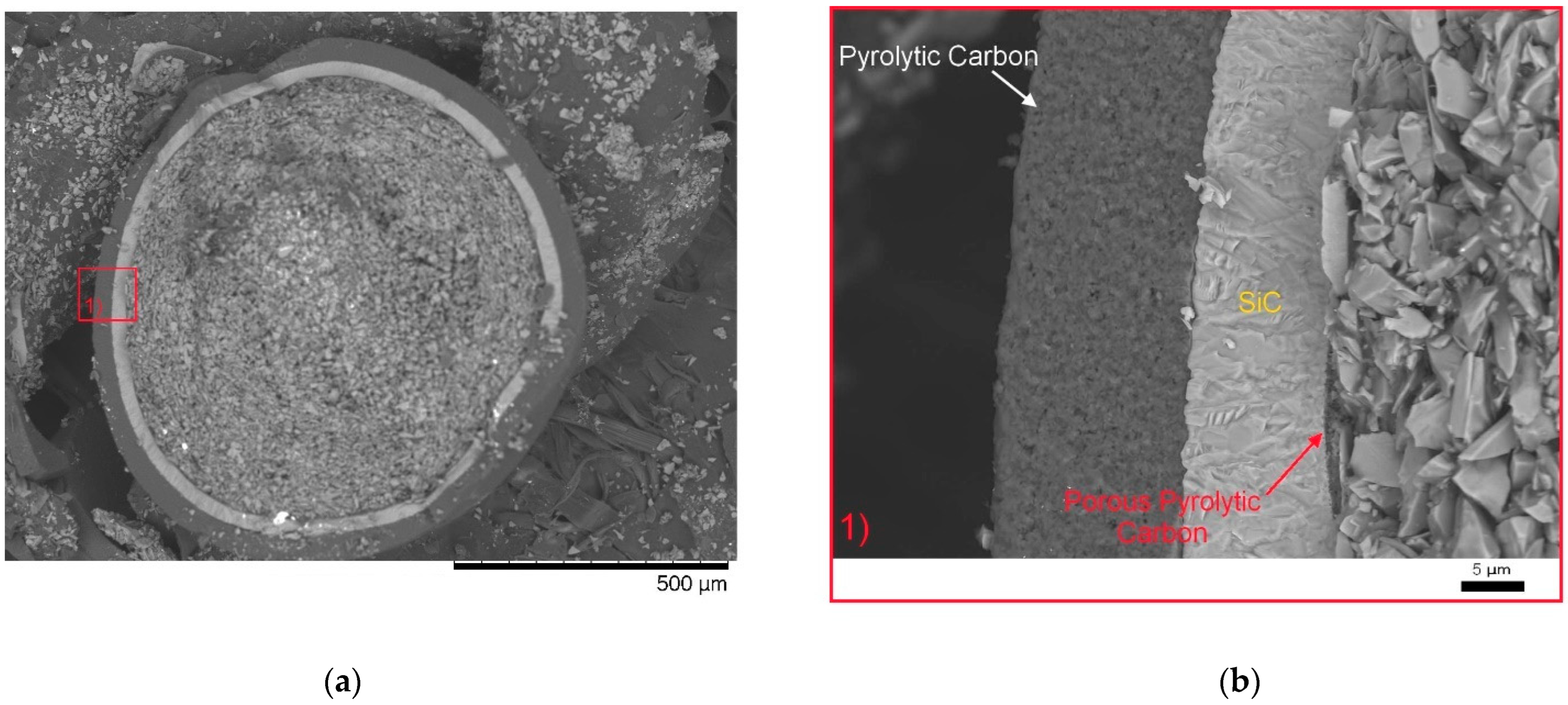
| Coating Layers | Technical Characteristics |
|---|---|
| Layer thickness (μm) | |
| Buffer | 95 ± 30 |
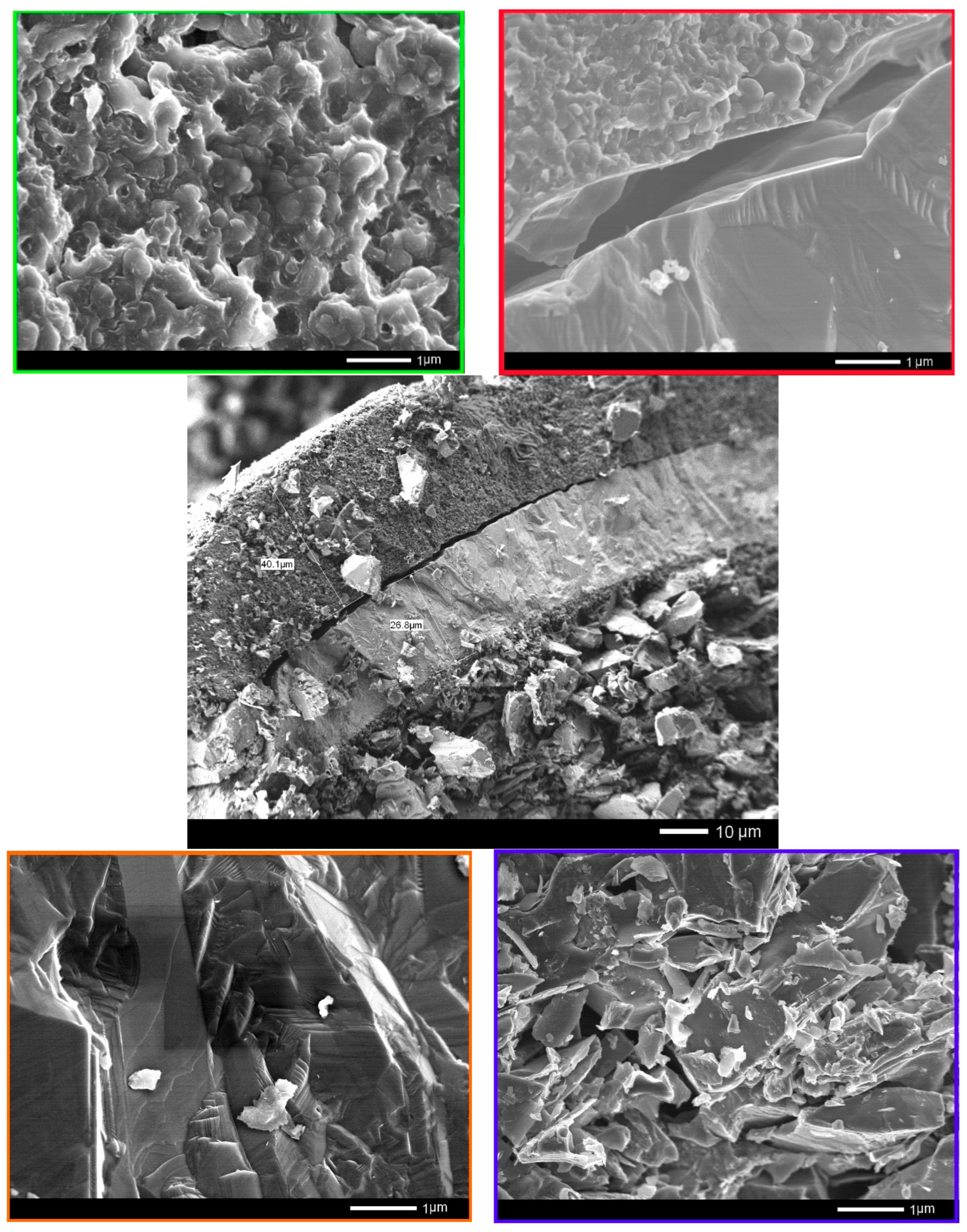
| I-PyC | 40 ± 8 |
| SiC | 35 ± 5 |
| O-PyC | 40 ± 6 |
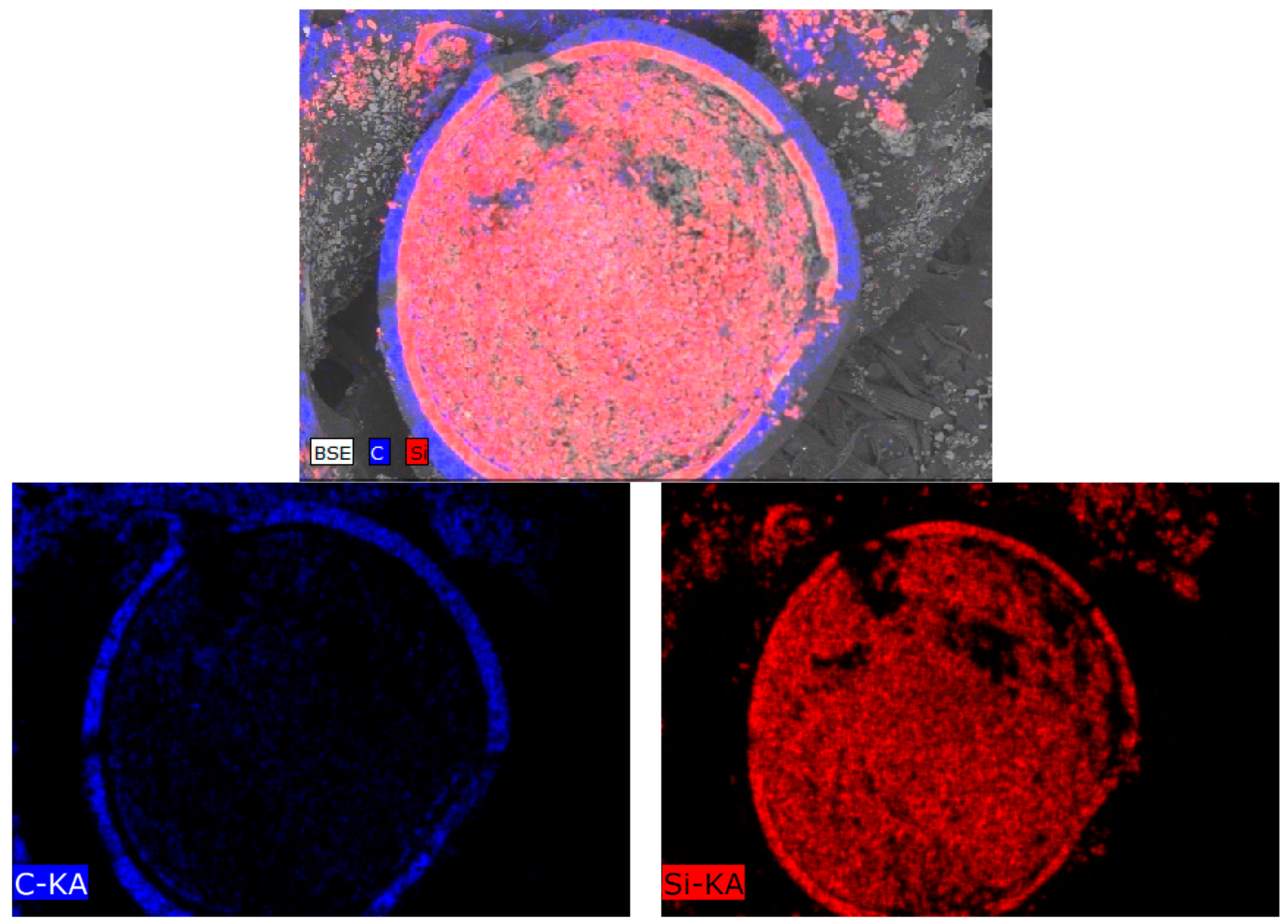
| Layer density (chemical composition) (g/cm3) | |
| Buffer (Pyrolytic carbon) | 1.05 + 0.15/−0.05 |
| I-PyC (Pyrolytic carbon) | 1.85 ± 0.10 |
| SiC (Silicon carbide) | ≥3.19 |
| O-PyC (Pyrolytic carbon) | 1.85 ± 0.10 |
Publisher’s Note: MDPI stays neutral with regard to jurisdictional claims in published maps and institutional affiliations. |
© 2022 by the authors. Licensee MDPI, Basel, Switzerland. This article is an open access article distributed under the terms and conditions of the Creative Commons Attribution (CC BY) license (https://creativecommons.org/licenses/by/4.0/).
Share and Cite
Kenzhina, I.; Blynskiy, P.; Kozlovskiy, A.; Begentayev, M.; Askerbekov, S.; Zaurbekova, Z.; Tolenova, A. Study of Morphological, Structural, and Strength Properties of Model Prototypes of New Generation TRISO Fuels. Materials 2022, 15, 4741. https://doi.org/10.3390/ma15144741
Kenzhina I, Blynskiy P, Kozlovskiy A, Begentayev M, Askerbekov S, Zaurbekova Z, Tolenova A. Study of Morphological, Structural, and Strength Properties of Model Prototypes of New Generation TRISO Fuels. Materials. 2022; 15(14):4741. https://doi.org/10.3390/ma15144741
Chicago/Turabian StyleKenzhina, Inesh, Petr Blynskiy, Artem Kozlovskiy, Meiram Begentayev, Saulet Askerbekov, Zhanna Zaurbekova, and Aktolkyn Tolenova. 2022. "Study of Morphological, Structural, and Strength Properties of Model Prototypes of New Generation TRISO Fuels" Materials 15, no. 14: 4741. https://doi.org/10.3390/ma15144741
APA StyleKenzhina, I., Blynskiy, P., Kozlovskiy, A., Begentayev, M., Askerbekov, S., Zaurbekova, Z., & Tolenova, A. (2022). Study of Morphological, Structural, and Strength Properties of Model Prototypes of New Generation TRISO Fuels. Materials, 15(14), 4741. https://doi.org/10.3390/ma15144741