
Effect of Preheating Temperature on Geometry and Mechanical Properties of Laser Cladding-Based Stellite 6/WC Coating

 ,
,
Abstract
:1. Introduction
2. Research Methods
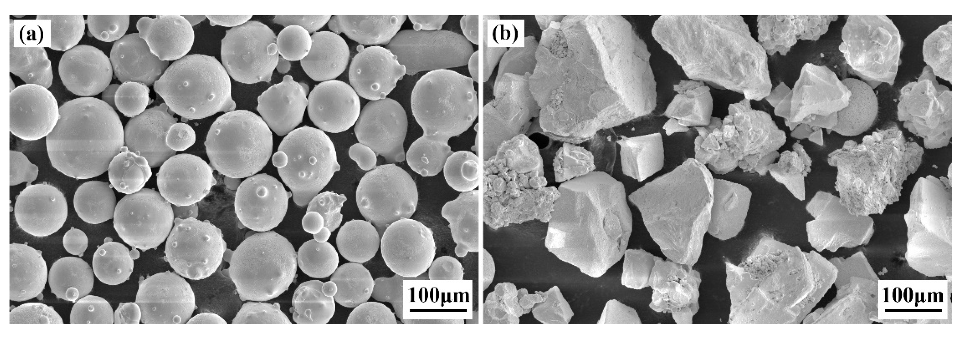
2.1. Materials
2.2. Laser Cladding Process Parameters
2.3. Surface Conditions and Microstructure Characterization
2.4. Mechanical Property Test
3. Results and Discussion
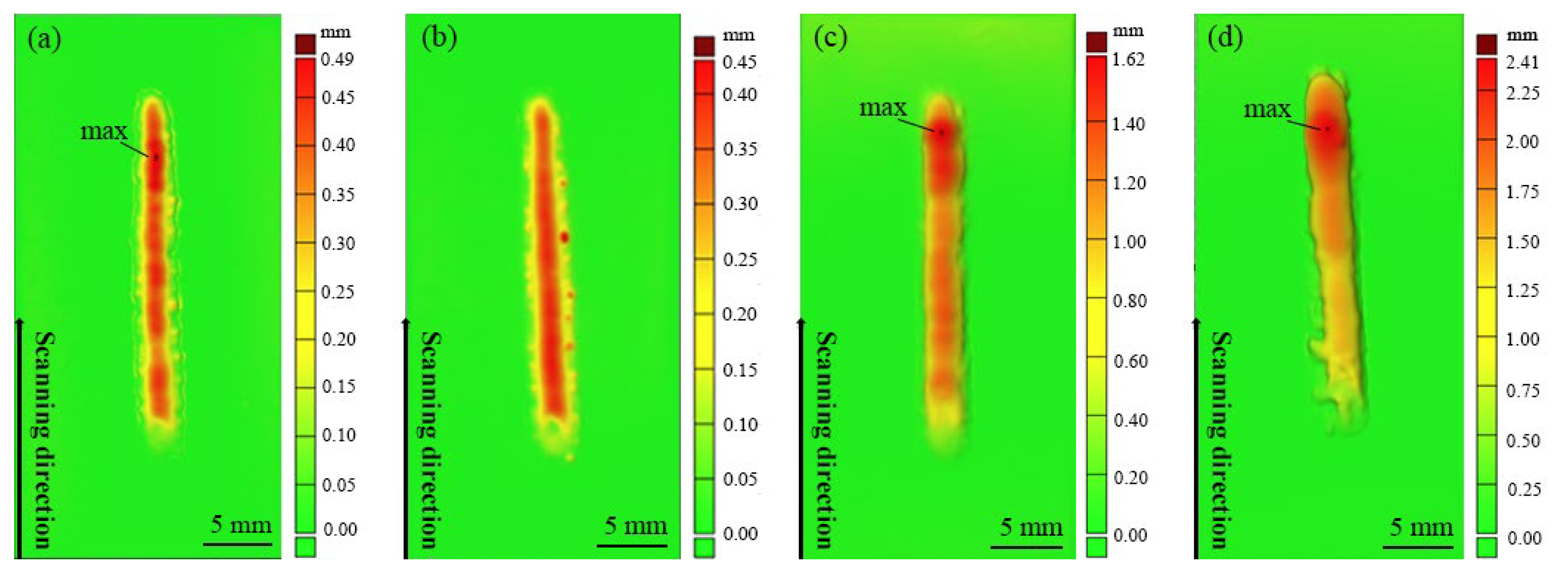
3.1. Surface Morphology of Different Specimens
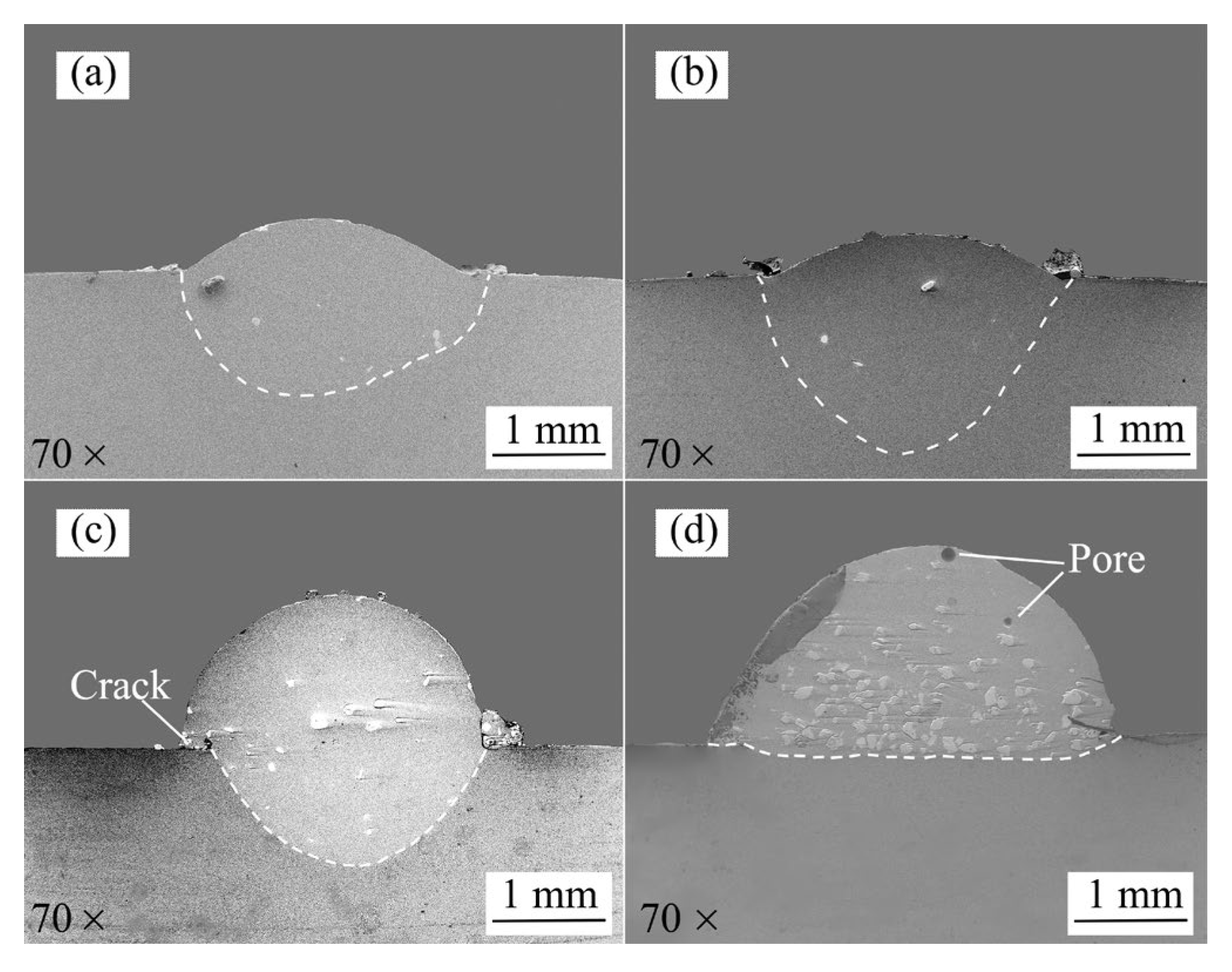
3.2. Cross-Sectional Characteristics of Different Specimens
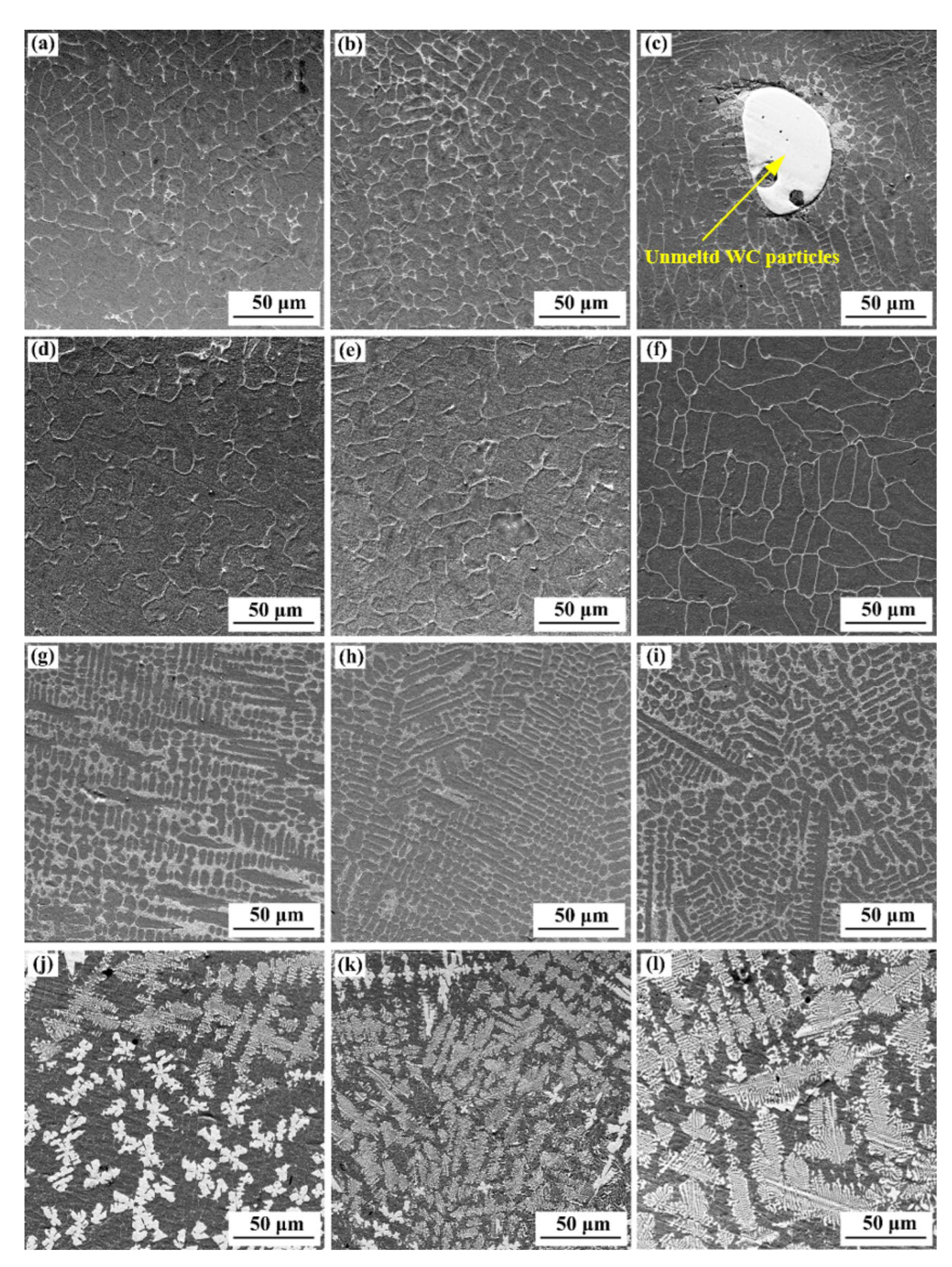
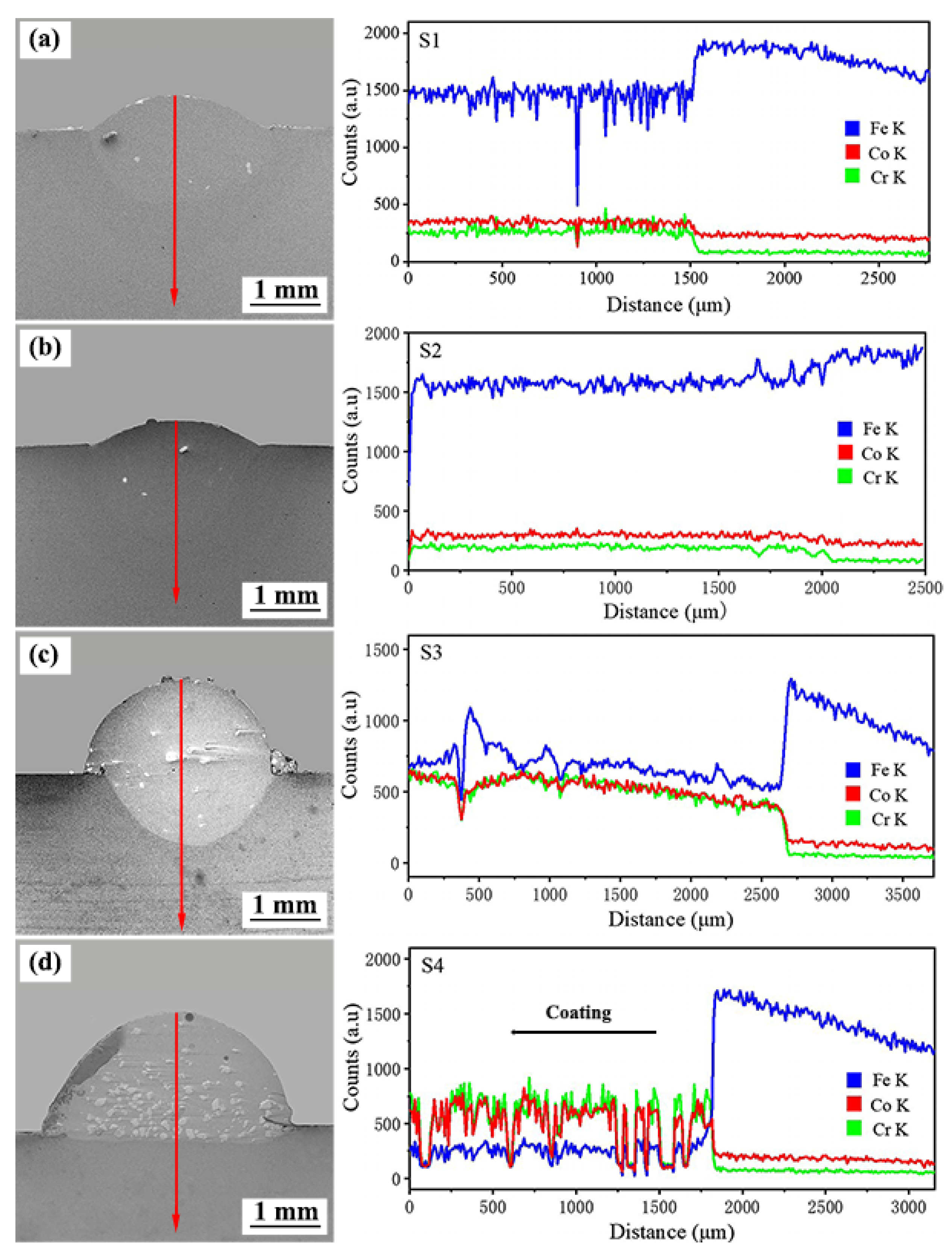
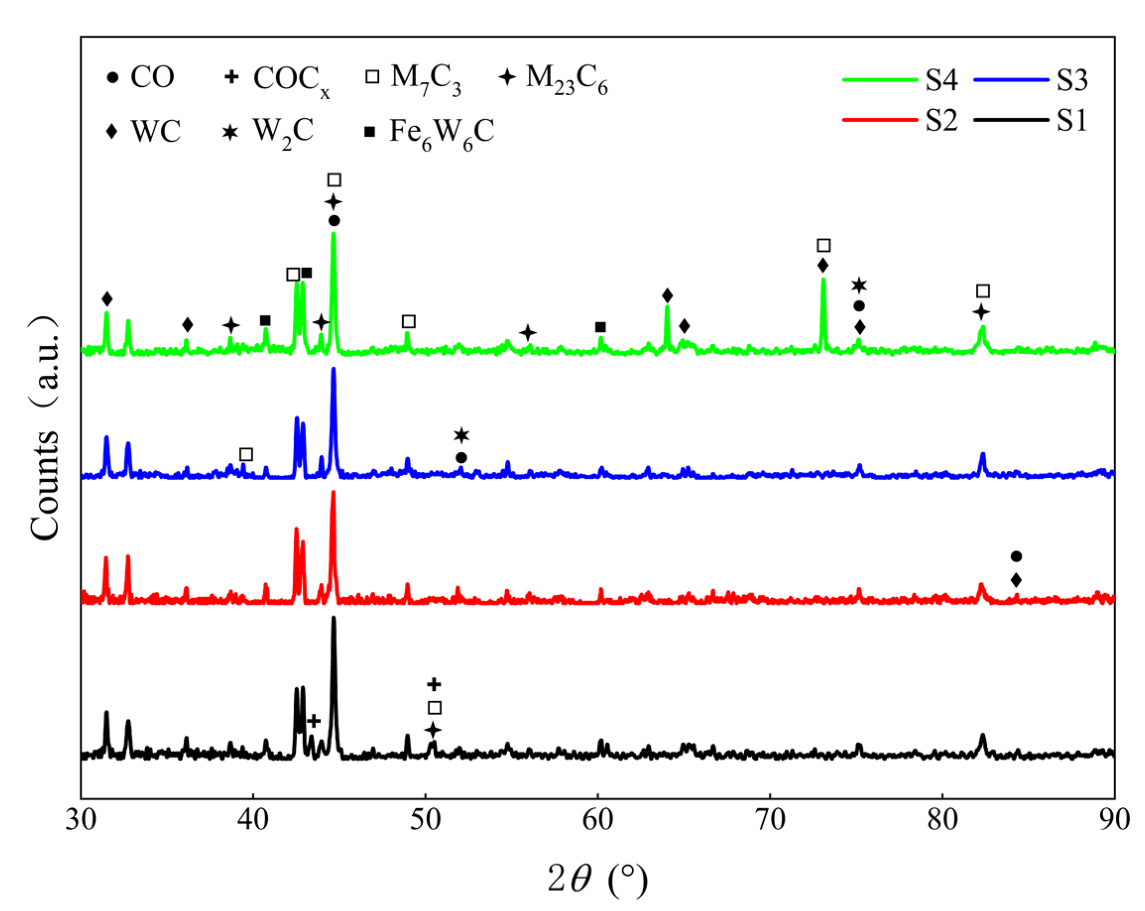
3.3. Microanalysis of Different Specimens
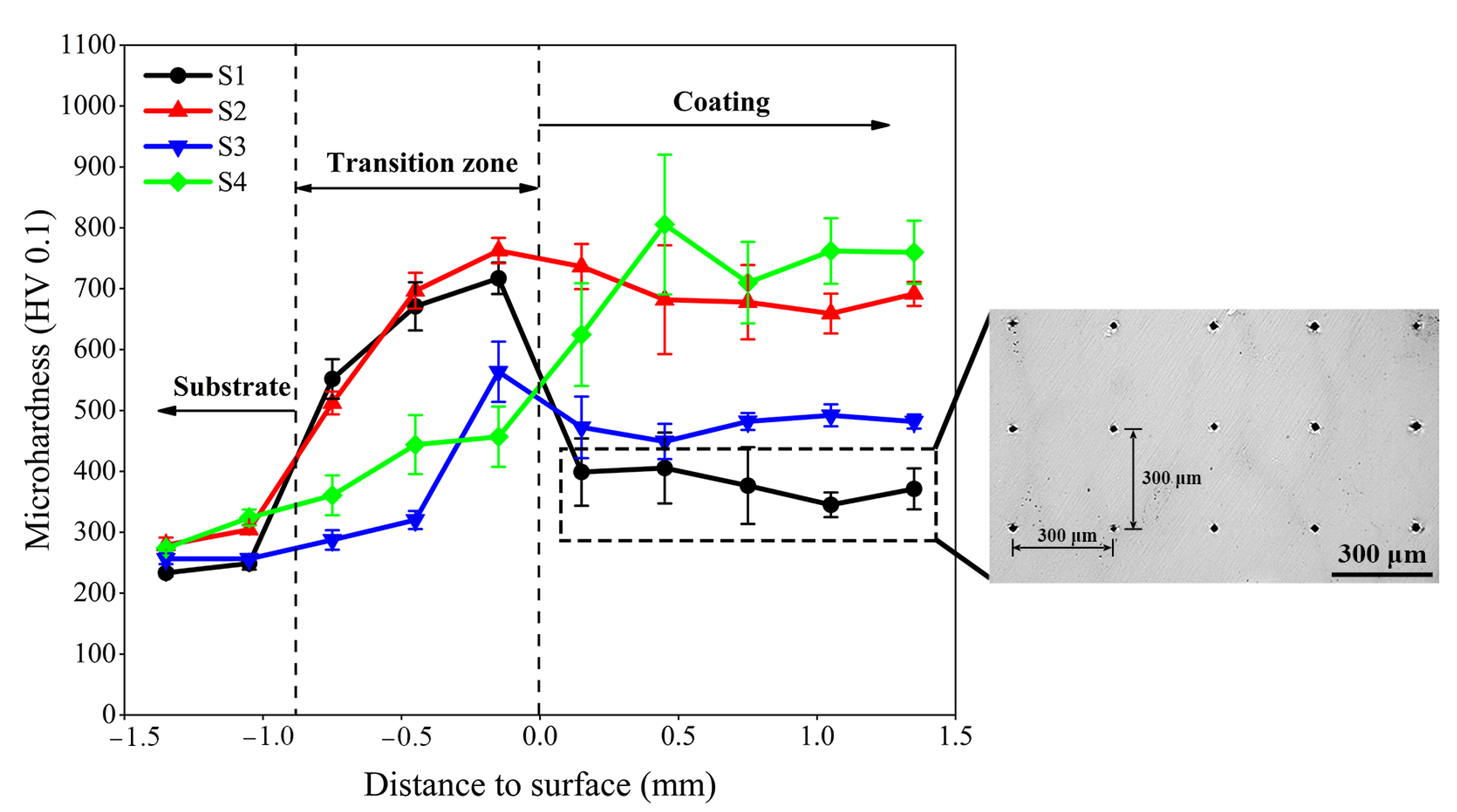
3.4. Microhardness Distribution of Different Specimens
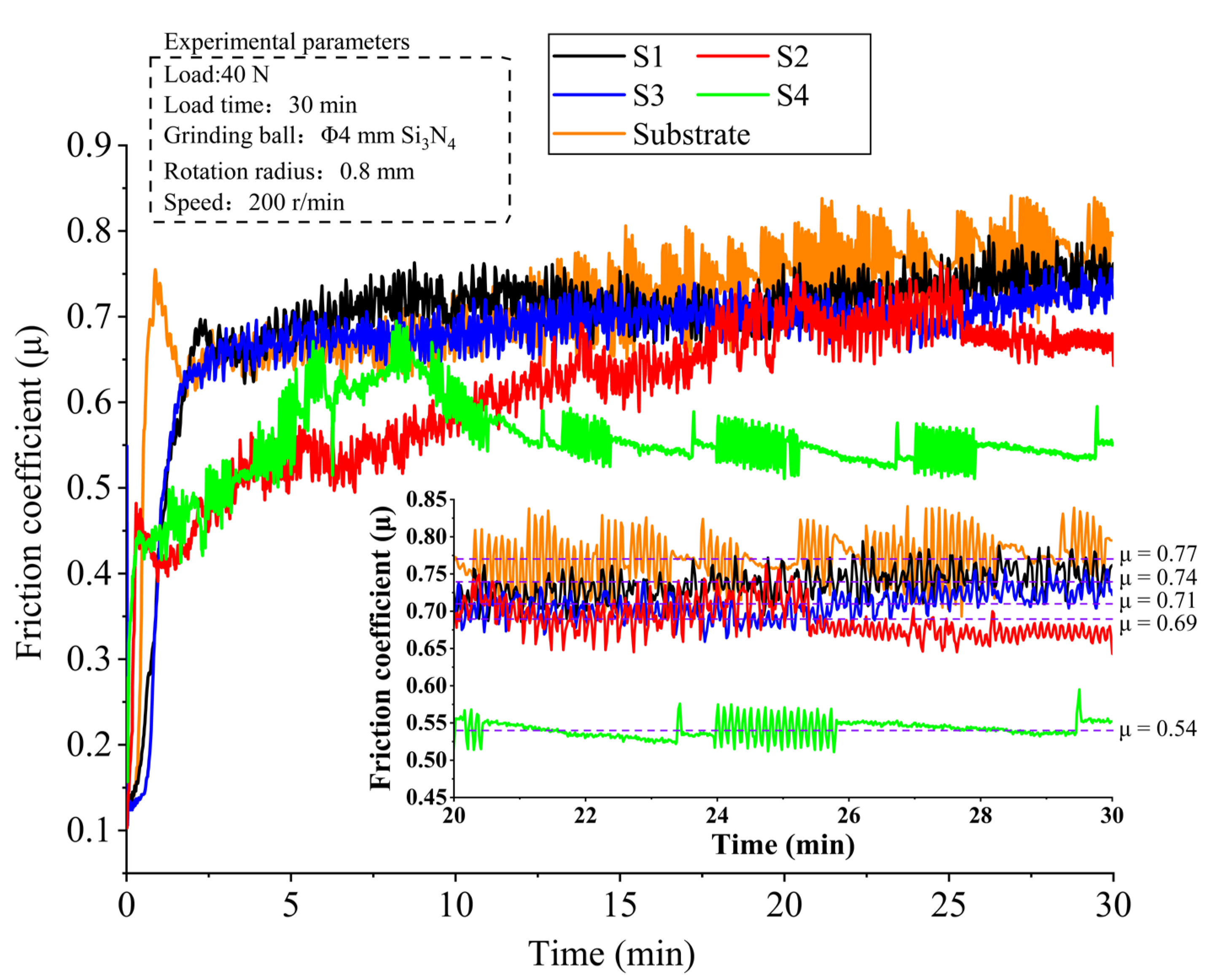
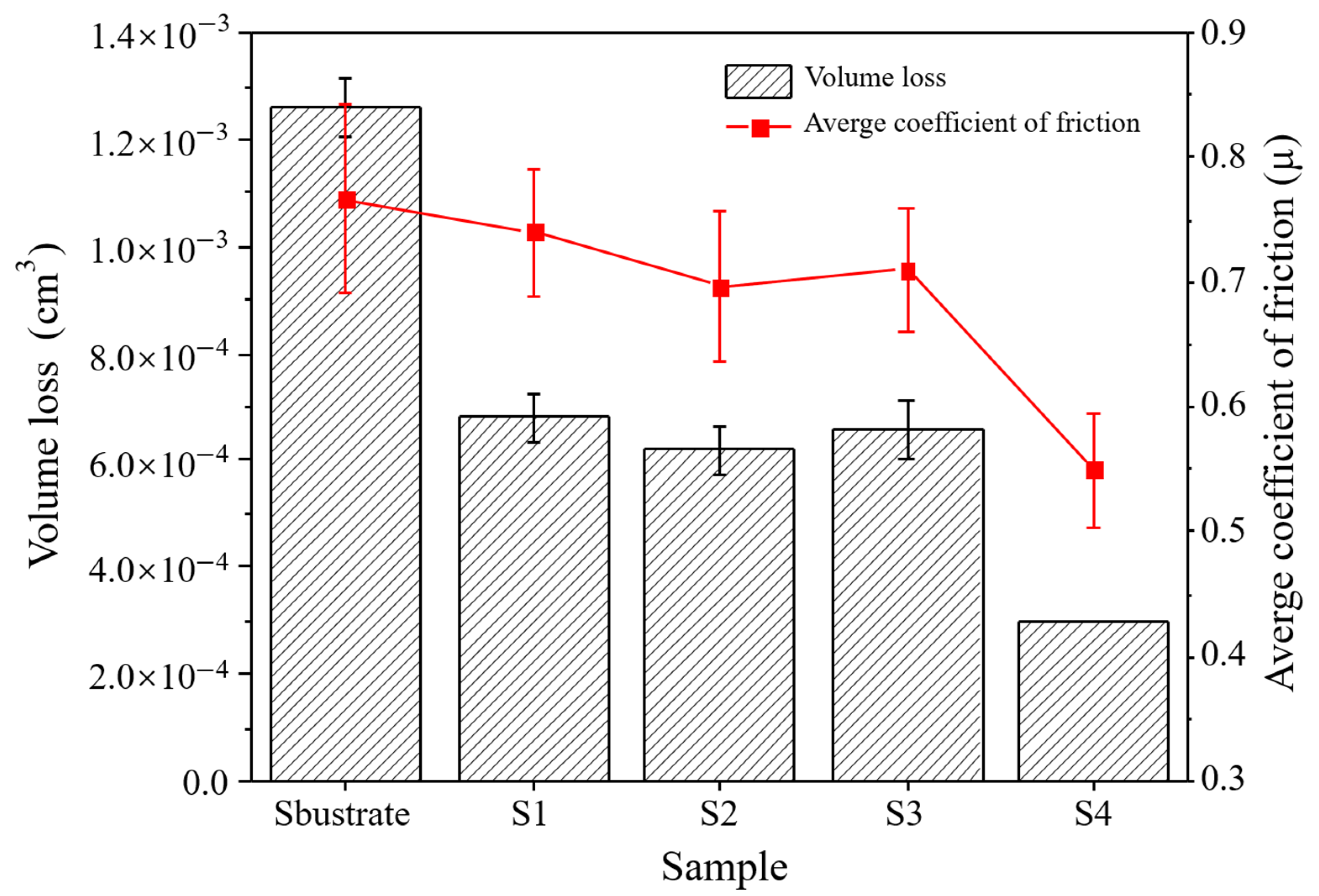
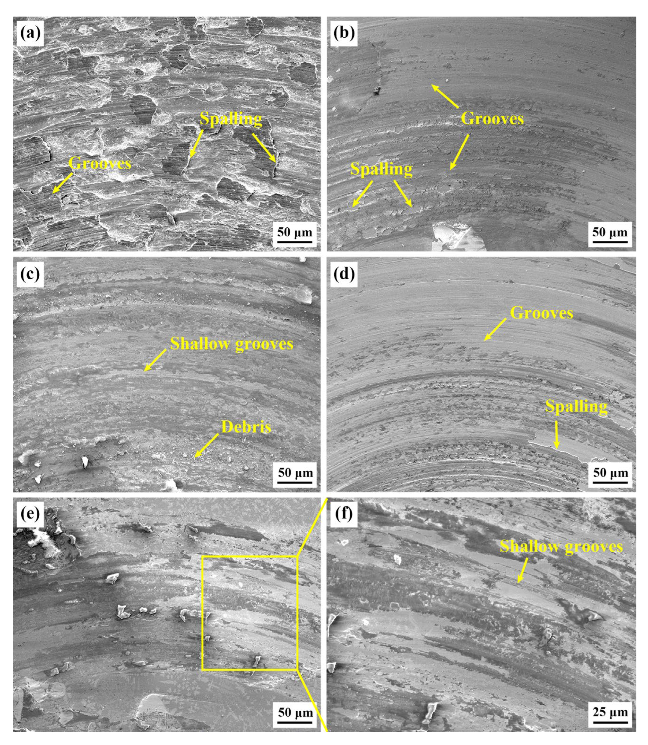
3.5. Wear Property Analysis
4. Conclusions
- 1.
- The surface height difference of the cobalt-based tungsten carbide composite coating falls initially and subsequently increases when the substrate preheating temperature rises, the coating height rises to 2.41 mm from 0.49 mm, and the cladding angle reduces dramatically.
- 2.
- By comparing four groups of coatings, the microstructure of the upper and middle parts of the cladding layer is mainly isometric crystal, and the microstructure of the lower part is columnar or cellular crystal at substrate preheating temperatures of room temperature, 150 °C, and 250 °C. At a substrate preheating temperature of 350 °C, the main structure of the cladding layer is various blocky, petaloid, and flower-like precipitates at a substrate preheating temperature of 350 °C.
- 3.
- The cobalt-based tungsten carbide composites are superior to 60Si2Mn steel in terms of hardness and wear properties. The hardness and wear resistance properties of the coating are optimal at a substrate preheating temperature of 350 °C. The hardness of the coating is 2.45 times higher than that of the substrate, and the average friction coefficient and the wear volume of the coating are 0.7 times and 0.24 times lower than those of the substrate, respectively.
Author Contributions
Funding
Institutional Review Board Statement
Informed Consent Statement
Data Availability Statement
Conflicts of Interest
References
- Liu, S.S.; Zhang, M.; Zhao, G.L.; Wang, X.H.; Wang, J.F. Microstructure and properties of ceramic particle reinforced FeCoNiCrMnTi high entropy alloy laser cladding coating. Intermetallics 2022, 140, 107402. [Google Scholar] [CrossRef]
- Liu, X.B.; Bi, J.Z.; Meng, Z.Y.; Li, R.; Li, Y.; Zhang, T. Tribological behaviors of high-hardness Co-based amorphous coatings fabricated by laser cladding. Tribol. Int. 2021, 162, 107142. [Google Scholar] [CrossRef]
- Wang, T.; Zhu, L.; Song, H.Y.; Wang, H. Effect of WC-17Co content on microstructure and properties of IN718 composites prepared by laser cladding. Opt. Laser Technol. 2022, 8, 107780. [Google Scholar] [CrossRef]
- Weng, F.; Chen, C.Z.; Yu, H.J. Research status of laser cladding on titanium and its alloys: A review. Mater. Des. 2014, 58, 412–425. [Google Scholar] [CrossRef]
- Zhao, S.B.; Xu, S.; Yang, L.J.; Huang, Y.M. WC-Fe metal-matrix composite coatings fabricated by laser wire cladding. J. Mater. Process. Technol. 2022, 301, 117438. [Google Scholar] [CrossRef]
- Bartkowski, D.; Bartkowska, A.; Jurči, P. Laser cladding process of Fe/WC metal matrix composite coatings on low carbon steel using Yb: YAG disk laser. Opt. Laser Technol. 2021, 136, 106784. [Google Scholar] [CrossRef]
- Zhang, K.M.; Zou, J.X.; Li, J.; Yu, Z.S.; Wang, H.P. Synthesis of Y2O3 particle enhanced Ni/TiC composite on TC4 Ti alloy by laser cladding. Trans. Nonferr. Met. Soc. China 2012, 22, 1817–1823. [Google Scholar] [CrossRef]
- Chen, L.Y.; Zhao, Y.; Chen, X.; Yu, T.B.; Xu, P.F. Repair of spline shaft by laser-cladding coarse TiC reinforced Ni-based coating: Process, microstructure and properties. Ceram. Int. 2021, 47, 30113–30128. [Google Scholar] [CrossRef]
- Mohammad, E.; Reza, S.R.; Hassan, A.P.; Hamidreza, M.S.; Masoud, B.; Sayed, H.H. Friction and wear behavior of laser cladded WC-Co and Ni/WC-Co deposits at high temperature. Int. J. Refract. Met. Hard Mater. 2019, 81, 137–148. [Google Scholar] [CrossRef]
- Li, W.; Xu, P.Q.; Wang, Y.Y.; Zou, Y.; Gong, H.Y.; Lu, F.G. Laser synthesis and microstructure of micro- and nano-structured WC reinforced Co-based cladding layers on titanium alloy. J. Alloys Compd. 2018, 749, 10–22. [Google Scholar] [CrossRef]
- Lin, C.M. Parameter optimization of laser cladding process and resulting microstructure for the repair of tenon on steam turbine blade. Vacuum 2015, 115, 117–123. [Google Scholar] [CrossRef]
- Sun, Y.W.; Hao, M.Z. Statistical analysis and optimization of process parameters in Ti6Al4V laser cladding using Nd:YAG laser. Opt. Lasers Eng. 2012, 50, 985–995. [Google Scholar] [CrossRef]
- Singh, A.K.; Bal, K.S.; Dey, D.; Das, A.K.; Pal, A.R.; Pratihar, D.K.; Choudhury, A.R. Experimental investigation and parametric optimization for minimization of dilution during direct laser metal deposition of tungsten carbide and cobalt powder mixture on SS304 substrate. Powder Technol. 2021, 390, 339–353. [Google Scholar] [CrossRef]
- Fan, P.F.; Zhang, G. Study on process optimization of WC-Co50 cermet composite coating by laser cladding. Int. J. Refract. Met. Hard Mater. 2020, 87, 105133. [Google Scholar] [CrossRef]
- Guo, C.G.; He, S.Z.; Yue, H.T.; Li, Q.; Hao, G.B. Prediction modelling and process optimization for forming multi-layer cladding structures with laser directed energy deposition. Opt. Laser Technol. 2021, 134, 106607. [Google Scholar] [CrossRef]
- Liu, H.M.; Qin, X.P.; Huang, S.; Hu, Z.Q.; Ni, M. Geometry modeling of single track cladding deposited by high power diode laser with rectangular beam spot. Opt. Lasers Eng. 2018, 100, 38–46. [Google Scholar] [CrossRef]
- Guo, Y.X.; Liu, Q.B. MoFeCrTiWAlNb refractory high-entropy alloy coating fabricated by rectangular-spot laser cladding. Intermetallics 2018, 102, 78–87. [Google Scholar] [CrossRef]
- Shi, T.; Lu, B.H.; Shi, S.H.; Meng, W.D.; Fu, G.Y. Laser metal deposition with spatial variable orientation based on hollowlaser beam with internal powder feeding technology. Opt. Laser Technol. 2017, 88, 234–241. [Google Scholar] [CrossRef]
- Xu, P.H.; Zhu, L.D.; Xue, P.S.; Meng, G.R.; Wang, S.H.; Yang, Z.C.; Ning, J.S.; Lan, Q. Multi-track alternated overlapping model suitable for variable laser cladding process parameters. Surf. Coat. Technol. 2021, 425, 127706. [Google Scholar] [CrossRef]
- Qi, K.; Yang, Y.; Liang, W.X.; Jin, K.; Xiong, L. Effect of magnetic field on the microstructure and wear properties of TiB2/ metal composite layers synthesized in situ by laser cladding on Ti–6Al–4V alloy. Ceram. Int. 2021, 47, 29463–29474. [Google Scholar] [CrossRef]
- Wen, X.; Cui, X.F.; Jin, G.; Zhang, X.R.; Zhang, Y.; Zhang, D.; Fang, Y.C. Design and characterization of FeCrCoAlMn0.5Mo0.1 high-entropy alloy coating by ultrasonic assisted laser cladding. J. Alloys Compd. 2020, 835, 155449. [Google Scholar] [CrossRef]
- Liu, H.X.; Xu, Q.; Wang, C.Q.; Zhang, X.W. Corrosion and wear behavior of Ni60CuMoW coatings fabricated by combination of laser cladding and mechanical vibration processing. J. Alloys Compd. 2015, 621, 357–363. [Google Scholar] [CrossRef]
- Zhou, S.F.; Zeng, X.Y.; Hu, Q.W.; Huang, Y.J. Analysis of crack behavior for Ni-based WC composite coatings by laser cladding and crack-free realization. Appl. Surf. Sci. 2008, 255, 1646–1653. [Google Scholar] [CrossRef]
- Farahmand, P.; Liu, S.; Zhang, Z.; Kovacevic, R. Laser cladding assisted by induction heating of Ni–WC composite enhanced by nano-WC and La2O3. Ceram. Int. 2014, 40, 15421–15438. [Google Scholar] [CrossRef]
- Bidron, G.; Doghri, A.; Malot, T.; Fournier-dit-Chabert, F.; Thomas, M.; Peyre, P. Reduction of the hot cracking sensitivity of CM-247LC superalloy processed by laser cladding using induction preheating. J. Mater. Process. Technol. 2020, 277, 116461. [Google Scholar] [CrossRef] [Green Version]
- Soffel, F.; Papis, K.; Bambach, M.; Wegener, K. Laser Preheating for Hot Crack Reduction in Direct Metal Deposition of Inconel 738LC. Metals 2022, 12, 614. [Google Scholar] [CrossRef]
- Liu, H.; Du, X.T.; Guo, H.F.; Liu, J.; Chen, P.J.; Yang, H.F.; Hao, J.B. Finite element analysis of effects of dynamic preheating on thermal behavior of multi-track and multi-layer laser cladding. Optik 2021, 228, 166194. [Google Scholar] [CrossRef]
- Lee, C.M.; Park, H.; Yoo, J.; Lee, C.; Woo, W.C.; Park, S. Residual stress and crack initiation in laser clad composite layer withm Co-based alloy and WC + NiCr. Appl. Surf. Sci. 2015, 345, 286–294. [Google Scholar] [CrossRef]
- Bartkowski, D.; Kinal, G. Microstructure and wear resistance of Stellite-6/WC MMC coatingsproduced by laser cladding using Yb:YAG disk laser. Int. J. Refract. Met. Hard Mater. 2016, 58, 157–164. [Google Scholar] [CrossRef]
- Xu, J.S.; Zhang, X.C.; Xuan, F.Z.; Tian, F.Q.; Wang, Z.D.; Tu, S.T. Tensile properties and fracture behavior of laser cladded WC/Ni composite coatings with different contents of WC particle studied by in-situ tensile testing. Mater. Sci. Eng. A 2013, 560, 744–751. [Google Scholar] [CrossRef]
- Xu, G.J.; Kutsuna, M. Cladding with Stellite 6 + WC using a YAG laserrobot system. Surf. Eng. 2006, 22, 345–352. [Google Scholar] [CrossRef]
- Karmakar, D.P.; Muvvala, G.; Nath, A.K. High-temperature abrasive wear characteristics of H13 steel modified by laser remelting and cladded with Stellite 6 and Stellite 6/30% WC. Surf. Coat. Technol. 2021, 422, 127498. [Google Scholar] [CrossRef]
- Xu, P.H.; Zhu, L.D.; Xue, P.S.; Yang, Z.C.; Wang, S.H.; Ning, J.S.; Meng, G.R.; Lan, Q.; Qin, S.Q. Microstructure and properties of IN718/WC-12Co composite coating by laser cladding. Ceram. Int. 2022, 48, 9218–9228. [Google Scholar] [CrossRef]
- Khorram, A.; Jamaloei, A.D.; Paidar, M.; Cao, X.J. Laser cladding of Inconel 718 with 75Cr3C2 + 25(80Ni20Cr) powder: Statistical modeling and optimization. Surf. Coat. Technol. 2019, 378, 124933. [Google Scholar] [CrossRef]
- Zhong, M.L.; Liu, W.J.; Yao, K.F.; Goussain, J.C.; Mayer, C.; Becker, A. Microstructural evolution in high power laser cladding of Stellite 6 + WC layers. Surf. Coat. Technol. 2002, 157, 128–137. [Google Scholar] [CrossRef]
- Zeng, X.B.; Wang, Q.T.; Chen, C.R.; Lian, G.F.; Huang, X. Effects of WC addition on the morphology, microstructure and mechanical properties of Fe50/TiC/WC laser claddings on AISI 1045 steel. Surf. Coat. Technol. 2021, 427, 127781. [Google Scholar] [CrossRef]
- Xi, W.C.; Song, B.X.; Wang, Z.X.; Yu, T.B.; Wang, J.; Dai, Y.X. Effect of laser re-melting on geometry and mechanical properties of YCF102 cladding layer. Surf. Coat. Technol. 2021, 408, 126789. [Google Scholar] [CrossRef]
- Rupert, T.J.; Schuh, C.A. Sliding wear of nanocrystalline Ni–W: Structural evolution and the apparent breakdown of Archard scaling. Acta Mater. 2010, 58, 4137–4148. [Google Scholar] [CrossRef]


| Steel Designation | Nominal Composition, wt% | ||||||
|---|---|---|---|---|---|---|---|
| C | Si | Mn | Ni | Cu | Cr | Fe | |
| 60Si2Mn | 0.56–0.6 | 1.5–2.0 | 0.6–0.9 | ≤0.35 | ≤0.25 | ≤0.35 | Bal |
| Stellite Alloy Grade | Nominal Composition, wt% | ||||||||
|---|---|---|---|---|---|---|---|---|---|
| C | Cr | Si | W | Fe | Mo | Ni | Co | Mn | |
| Stellite 6 | 1.15 | 29.00 | 1.10 | 4.00 | 3.00 | 1.00 | 3.00 | Bal | 0.50 |
| Specimen | Laser Power [W] | Scan Speed [mm/s] | Feeding Rate [g/min] | Shielding Gas [L/min] | Preheating Temperature [°C] |
|---|---|---|---|---|---|
| S1 | 1500 W | 5 | 13 | 10 | Room temperature |
| S2 | 150 | ||||
| S3 | 250 | ||||
| S4 | 350 |
Publisher’s Note: MDPI stays neutral with regard to jurisdictional claims in published maps and institutional affiliations. |
© 2022 by the authors. Licensee MDPI, Basel, Switzerland. This article is an open access article distributed under the terms and conditions of the Creative Commons Attribution (CC BY) license (https://creativecommons.org/licenses/by/4.0/).
Share and Cite
Wu, T.; Shi, W.; Xie, L.; Gong, M.; Huang, J.; Xie, Y.; He, K. Effect of Preheating Temperature on Geometry and Mechanical Properties of Laser Cladding-Based Stellite 6/WC Coating. Materials 2022, 15, 3952. https://doi.org/10.3390/ma15113952
Wu T, Shi W, Xie L, Gong M, Huang J, Xie Y, He K. Effect of Preheating Temperature on Geometry and Mechanical Properties of Laser Cladding-Based Stellite 6/WC Coating. Materials. 2022; 15(11):3952. https://doi.org/10.3390/ma15113952
Chicago/Turabian StyleWu, Teng, Wenqing Shi, Linyi Xie, Meimei Gong, Jiang Huang, Yuping Xie, and Kuanfang He. 2022. "Effect of Preheating Temperature on Geometry and Mechanical Properties of Laser Cladding-Based Stellite 6/WC Coating" Materials 15, no. 11: 3952. https://doi.org/10.3390/ma15113952
APA StyleWu, T., Shi, W., Xie, L., Gong, M., Huang, J., Xie, Y., & He, K. (2022). Effect of Preheating Temperature on Geometry and Mechanical Properties of Laser Cladding-Based Stellite 6/WC Coating. Materials, 15(11), 3952. https://doi.org/10.3390/ma15113952